Hitec RCD OPTIC6SP72 REMOTE CONTROL TRANSMITTER User Manual optic 6 sp
Hitec RCD Inc. REMOTE CONTROL TRANSMITTER optic 6 sp
USERS MANUAL

Table of Contents - Page 2 Table of Contents - Page 3
The Optic Sport's advanced features include:
ㅁ Model Memory: The computer's memory is capable of
storing all the necessary trim settings and all the mixes and
their nuances for each model (up to a total of ten models in the
Optic Sport).
The memory is non-volatile-that is, it won't be lost even if the
transmitters battery is discharged or even removed.
ㅁ Shift Selectable: The signal output is shift-selectable:
Within the initial setup menu you can tell the transmitter to
output its signal in either positive or negative shift.
This means any FM receiver, no matter what the brand,
will work with this transmitter.
ㅁ Pre-mixed Flight Control Functions:
The Optic Sport's computer automatically mixes rudder and
elevator outputs to control a V-tail or mixes aileron and elevator
outputs to create elevons for tail-less flying wings, eliminating
the need for on-board mixing systems.
Other pre-mixes include an aileron-to-rudder mix so turns are
automatically coordinated and an elevator-to-flap mix for
snap-turns.
ㅁ Sub-Trim Function: This computerized radio allows you to
easily fine-tune and coordinate the control surfaces (such as
keeping a rudder centered or two ailerons-each on their own
servo-moving the same amount) without having to physically
re-adjust linkages.
ㅁ Buddy-Box Function:
For those learning to fly, the transmitter has a "buddy-box"
capability so that you can use the optional trainer cord
(part # xxxx) to connect your Optic Sport to a second Hitec
transmitter.
This allows one transmitter to be used by an instructor as the
primary flight control while the other is controlled by the student
pilot.
Releasing a button instantly diverts control from the student's
"slave" back to the master transmitter.
ㅁ Open Mix Capability:
The Optic Sport also features one "open-mix" in which you can
choose any two channels to mix
the servos master-to-slave, such as mixing the throttle with the
elevator to counteract pitching or the throttle with the rudder to
reduce yawing
If this is your first programmable radio control transmitter,
you're probably feeling a bit overwhelmed by all the buttons
and switches on the case and the cryptic symbols that appear
on the radio's LCD screen.
However, if you take the time to read this manual and follow the
programming steps as you watch your model's control surfaces
respond, programming the Optic Sport will soon become quite
routine.
So stick with it-learning the programming basics won't take any
longer or require any more brain power than it takes to do the
average crossword or Sudoku puzzle.
You'll discover that the rewards for mastering this simple but
powerful computerized, programmable radio are well worth the
effort.
*The Tip Sheet*
Throughout the manual you will see our "Tip Sheet" notes.
These highlight specific function details we didn't want you
to miss within the body of the manual. Check these out,
they can make programming the Optic Sport easier.
Congratulations! You now own a basic, but unusually versatile
and powerful, 6-Channel programmable RC transmitter.
The Optic Sport is all the radio you need to fly most types of
fixed-winged aircraft-from standard trainers to flying wings to
3-D aerobatic models to sailplanes (both powered or pure)-as
well as most classes of helicopters. As you will learn later in
this manual, the ability of this radio to mix and control many of
the channel outputs in a variety of ways allows you to create
some surprisingly sophisticated flying functions that were once
available only in much more complex and expensive radios.
Standard programming features include servo-reversing for all
channels, subtrim adjustments on all channels, end point
adjustment on all channels and selectable dual rate and
exponential values for the ailerons, elevator and rudder.
The primary limitation of this radio is that your models require
six or less control channels.
Introducing the Optic Sport
If you are new to Computerized RC Transmitters:
Introducing the Optic Sport
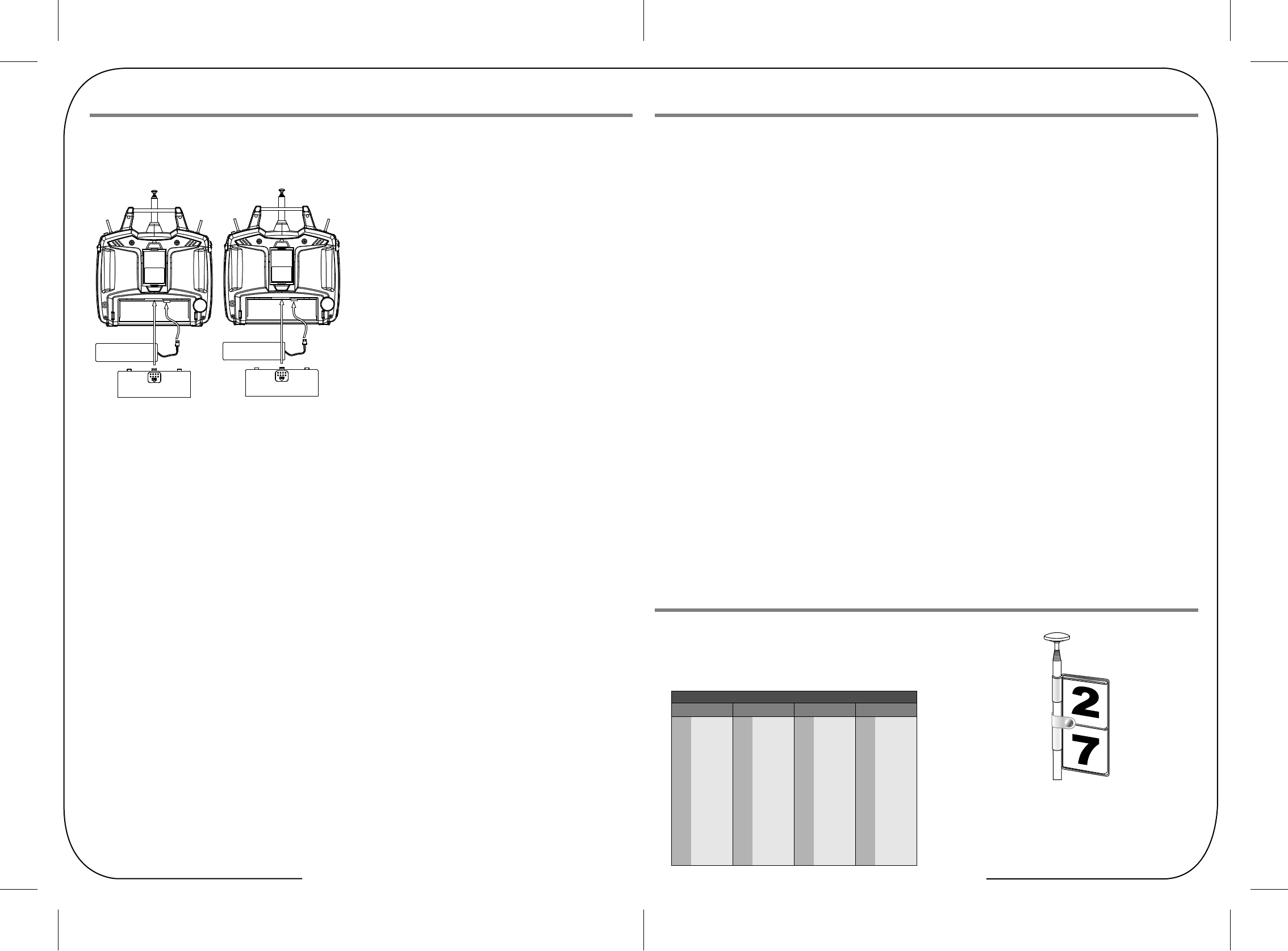
Table of Contents - Page 4 Table of Contents - Page 5
Be careful if you do choose to use a field charger on your batteries.
A fast-charger may overcharge the batteries, causing overheating
and a premature failure. Never charge your transmitter or receiver
battery at a rate higher than the batteries capacity.
For example, the capacity of your Optic 6 Sport's 7.2 volt
NIMH battery is 1300 mAh and should therefore not be charged at
a rate any higher than 1.3 amps.
Be sure to recharge the batteries before each flying session.
A battery low in charge will soon die, causing loss of control and
a crash. Plug in the charger that comes in this system and hook up
the transmitter and airborne batteries the day before a planned
flying session. Be sure the charger is not turned off by the room's
light on-off switch!
Important!: Quit flying when your transmitter battery level
reaches 6.6 volts-the radio will emit a steady series of beeps to
remind you!
Mode 1 Configuration
All Optic Sport systems sold in America are in the
Mode 2 format. While most pilots in America fly with their
transmitter in the "mode 2" configuration, you may wish to
use your new Optic sport in the "mode 1" format.
There is a choice for this option in the Model Set-Up function
menu described on Page XX. After selecting Mode 1 in the
Model Set-Up menu, You must do the following to change
the Optic Sport transmitter to Mode 1. We must add this info later.
Once you arrive at the flying field...
Before flying, be sure that the frequency you intend to fly with is
not in use, and secure any frequency control device (pin, tag, etc.)
for that frequency before turning on your transmitter.
Never believe that it's possible to fly two or more models on the
same frequency at the same time. Even though there are different
types of modulation (AM, PPM or FM, and PCM), only one model
may be flown on a single frequency.
When you are ready to fly your model, position the throttle stick or
switch to its low speed or off position. Then, you may turn on the
transmitter power followed by the receiver power.
Use the LOCK function to prevent accidental throttle commands.
When you have finished flying, turn off the receiver power
first- then turn off the transmitter power. If you do not follow these
procedures, the receiver has no information to hold the servos
steady and you may damage your servos or control surfaces or
flood your motor. In the case of electric-powered models the motor
may unexpectedly turn on and cause a severe injury if the transmitter
is switched off before the receiver..
Before starting the engine, fully retract the transmitter antenna,
power up the transmitter and receiver, and check to be sure that
the servos follow the movement of the sticks. If a servo operates
abnormally, don't attempt to fly until you determine the cause of
the problem. Finally, before starting the engine, be sure to check
that the transmitter model memory is correct for the chosen model.
While you're getting ready to fly, if you place your transmitter on
the ground, be sure that the wind won't tip it over.
If it is knocked over, the throttle stick may accidentally get moved
causing the engine to race unexpectedly, causing damage or injury
to anyone nearby.
Before taxiing, be sure to extend the transmitter antenna to
its full length.
A collapsed antenna will reduce your flying range and may cause a
loss of control. It is a good idea to avoid pointing the transmitter
antenna directly at the model at all times, since the signal is weakest
in that direction.
Finally, don't fly in the rain! Water or moisture may enter
the transmitter through the antenna or stick openings and cause
erratic operation or loss of control. If you must fly in wet weather
during a contest, be sure to protect your transmitter with a plastic
bag or waterproof barrier.
To ensure your own safety and the safety of others,
please observe the following precautions:
Flying field
We recommend that you fly at a recognized model airplane flying field.
You can find model clubs and fields by asking the nearest hobby dealer,
or contacting the Academy of Model Aeronautics.
Always pay particular attention to the flying field's rules, as well as
the presence and location of spectators, the wind direction, and
any obstacles on the field. Be very careful flying in areas near
power lines, tall buildings, or communication facilities as there
may be radio interference in their vicinity.
If you must fly at a site that is not a club field, be sure there are
no other modelers flying within a two-mile range, or you may lose
control of your aircraft (or you may cause them to lose control of theirs).
NOTE: If you need to remove or replace the transmitter battery, do not pull
on its wires to remove it. Instead, gently pull on the connector's plastic
housing where it plugs in to the transmitter. The battery must be removed
to charge it properly with a "peak" charger.
Flying Safely
Frquency Control
Charge the Batteries!
Frequency Control
The following frequencies and channel numbers may be used for
flying aircraft in the U.S.
(this information specific to North American versions of the Optic):
It is very important to display your transmitters channel number
at all times.
To install your frequency flag device on your transmitter's antenna,
slide the appropriate paper numbers into the slots and slip the
device onto the transmitter's antenna.
ㅁTry to charge the batteries with the charger supplied with your system
exclusively. The use of a fast-charger may damage the batteries by
overheating and dramatically reduce their lifetime.
Before we dive into the programming and use of the Optic Sport,
let's charge the batteries.
1. Connect the transmitter charging cord to the transmitter's
charging socket (on the rear of the case, left side).
2. If your aircraft uses a receiver battery, connect it to the
receiver connector on the charging cord.
3. Plug the charger into a wall socket.
4. The charger's LEDs should light, indicating charging current
is flowing..
If either light does not turn on, verify that the transmitter and
receiver power switches are OFF.
Also be sure the wall switch controlling the room lights does
not shut off the charger's electrical outlet when you leave the
room.
The batteries should be left on charge for about 15 hours.
11 72.010
12 72.030
13 72.050
14 72.070
15 72.090
16 72.110
17 72.130
18 72.150
19 72.170
20 72.190
21 72.210
22 72.230
23 72.250
24 72.270
25 72.290
26 72.310
27 72.330
28 72.350
29 72.370
30 72.390
31 72.410
32 72.430
33 72.450
34 72.470
35 72.490
36 72.510
37 72.530
38 72.550
39 72.570
40 72.590
41 72.610
42 72.630
43 72.650
44 72.670
45 72.690
46 72.710
47 72.730
48 72.750
49 72.770
50 72.790
51 72.810
52 72.830
53 72.850
54 72.870
55 72.890
56 72.910
57 72.930
58 72.950
59 72.970
60 72.990
Ch.No. MHz Ch.No. MHz Ch.No. MHz Ch.No. MHz
72 MHz band
Table of Contents - Page 6 Table of Contents - Page 7
On-Off Switch
Optic Sport Programming Switches and Buttons Optic Sport In-Flight Controls
SAFETY NOTE:
If you hear the radio suddenly begin to emit a steady beep,
it means that the system voltage has dropped down to 6.6 volts.
Land as soon as the runway is clear so you can switch the radio
off and recharge its battery.
(See the battery charging sidebar AT DIRECTION).
"EDIT" buttons
This pair of buttons has three basic functions: they get you into
the initial setup menu when you hold both EDIT buttons down
and then turn on the radio; they get you into the model setup menu
when you push both down when the radio is already on;
and once you are in either of these menus pushing one button
scrolls you up or down through the list of menu items.
"DATA" buttons
As the "+" and "-" symbols imply, these buttons allow you to change
a numerical value (most often a % value of servo travel) up or down
within a menu item. When not in the programming mode either of
these buttons enable the countdown timer.
"LOCK" button
This button is primarily a safety feature for powered models:
When you push this button down the throttle servo on the model
is taken off-line so that an accidental movement of the throttle stick
won't change the setting. Get in the habit of using this function
whenever you are carrying your model to the flight line.
SAFETY NOTE:
KEEP YOUR HANDS AWAY FROM THE PROPELLER OR
ROTORS EVEN AFTER ENABLING THE LOCK FUNCTION-A
RADIO GLITCH COULD STILL ACTIVATE THE THROTTLE SERVO!
"CLEAR" button
You can use the clear button whenever you want to reset a
numerical value to its starting point. It is also used in one of the
menu screens (the P MIX TRM) to turn a function on or off.
Insert drawing showing in-flight controls on the case of the radio for ACRO, GLID and HELI
On-Off switch
This switch does more than just turn the radio on and off-it also
gets you into the initial setup programs when you hold down the two
"EDIT" buttons as you slide the switch from "off" to "on".
When you turn off the switch after making selections in the initial
setup menu, you "lock" your choices into the radio for this particular
model slot. The switch is coupled to the light located a couple of
inches above it-it comes on when the switch comes on and goes
off when the switch is turned
"CURSOR" buttons
When you are in a particular menu item, you'll use these
two buttons to scroll within it-most commonly to the right or left to
select a servo channel. When not in the programming mode,
these buttons start, stop and reset the radio's countdown timer.
EDIT DATA
CURSOR
TIMER RESET
TIMER MODE
TIMER START
LOCK CLEAR
Trainer or
engine Cut
Switch
SW 2
Aileron Dual
Elevator
Rudder
Dual Rate Switch
SW 1
GEAR
FLT.MODE ST-3
Rudder -
Throttle Stick
Aileron &
Elevator Stick
Throttle
Trim Switch
Elevator
Trim Switch
Rudder
Trim Switch
Aileron
Trim Switch
Power Switch
SW 3
Flight Mode
Switch
Table of Contents - Page 8 Table of Contents - Page 9
Timer
If you push either DATA button, you will enable the radio's timer
mode.
The word "TIMER" appears on the screen as well as a number
indicating the starting countdown time (which you can set in the
Initial Setup menu). If you push the right hand CURSOR button,
the timer will start counting down and the numbers will diminish in
one-second increments. Push it again and the countdown stops.
Pushing the left hand CURSOR button resets the timer.
Lock Indicator Screen
When you push the Lock button to hold the throttle at an idle,
the word "LOCK" appears in a black box above the voltage value.
When you push the lock button again, this symbol disappears to
indicate that you have disabled the function.
Receiver-Servo Connection List
Transmitter Displays and Messages
The table below shows where the aircraft's servos should plug into a six-channel receiver. Note that some functions shown will not operate
until they are activated in the transmitter. The standard function is listed first for each channel.
When you first turn on your transmitter, the first screen shown
below appears on the LCD display. Before flying, or even starting
the engine,
BE SURE that the model number appearing next to the voltage
matches the model that you are about to fly! If you don't, reversed
servos and incorrect trims will lead to an immediate crash.
If you press timer or engine cut or lock keys, you go directly to
those functions regardless of the display.
This screen appears whenever you turn on the transmitter without
pushing any other buttons.
The model number currently enabled is the small number just to
the right of the battery voltage and the programming baseline for
this model (ACRO, GLID or HELI) is shown in the upper left hand
corner.
In the center bottom of the screen "NOR" appears in a small black
box indicating that the transmitter is in the "Normal" flight mode
condition.
Startup Screen
Rx. Ch. ACRO GLID HELI
ileron Aileron Roll Cyclic
One or Right Flaperon (FLPN ON) or Right Aileron (ADIF on) or Swash servo 1 (120¡Æ
or Right Elevon
Elevator Elevator Pitch Cyclic
Two or Right V tail (VTAL on) or Right V tail (VTAL on) or Swash servo 2 (120¡Æ)
or Left Elevon (ELVN on)
Three Throttle Throttle Throttle
Four Rudder Rudder Tail Rotor
or Left V tail (VTAL on) or Left V tail (VTAL on)
Five Landing Gear Left Aileron (ADIF on) Gyro Gain
Six Flap Flap Collective
Left Aileron (FLPN on) or Swash Servo 3 (120¡Æ)
"SW-1" switch
Depending on the initial set-up base-line programming you have
selected, this switch can be used to lower landing gear; operate
the throttle of an electric motor (as on a powered glider); or select
a flight condition mode.
"SW-2" switch
This is your "Dual-rate" switch: The "0" position typically selects
the full rate of movement of the aileron, elevator and rudder while
the "1" position selects the diminished rate you have programmed
in the model setup menu. The exponential values for these control
surfaces (explained below) are also selected by this switch.
"SW-3 FLT MODE" switch
This switch allows you to choose three different "flight condition
modes"-an advanced programming function explained below.
"Eng Cut"/"Trainer" switch
If you've activated the engine cut function in the model setup menu
programming, this button serves as the kill-switch for your motor.
Otherwise, it functions as the trainer switch when your transmitter
is linked via a cable to a second transmitter to act as a "buddy box"
for flight training.
As long as you hold down the training button the buddy box will
be flying the model-let go of the button and your transmitter reverts
to being the master.
Trim switches
Use these switches to make small offset adjustments to the
servos controlled by the two joysticks.
Any adjustments will be "memorized" for this particular model
so you won't have to re-trim every time you fly.
Joystick
Again assuming the "Mode 2" configuration, this stick controls the
rudder (left and right) and the throttle (forward and back-back is off
for electric motors and idle for glow). If you have selected "GLID"
as the transmitter's programming baseline in the initial setup menu
than the stick's forward and back movement controls the ailerons
and flaps for the model's descent control (called "CROW").
Right-hand joystick
Left-hand joystick
Assuming you have selected "Mode 2" in the initial setup menu
(the most common control arrangement in North America),
this stick controls the elevator (forward is down and back toward
you is up) and the ailerons (left and right).
LEFT RIGHT
RIGHT
LEFT
Front View
LEFT
RIGHT
LEFT RIGHT
RIGHT
LEFT
Front View
LEFT
RIGHT
DOWN
UP
DOWN
UP UP
DOWN
HIGH
LOW
HIGH
LOW
HIGH Position:
carburetor fully opened
LOW Position:
carburetor at idle position
(not fully closed)
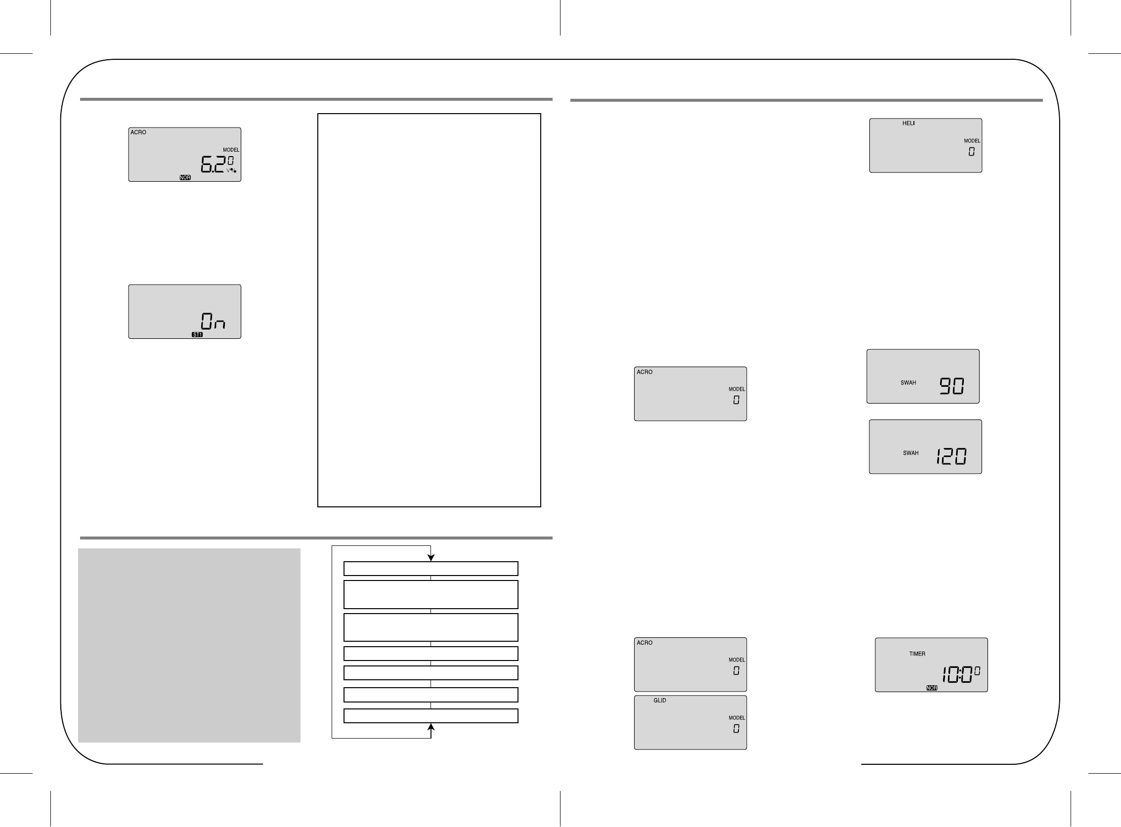
Table of Contents - Page 10 Table of Contents - Page 11
Menu Flow List
Model Number Choice
Model Type
Swash Type, 90 or 120 (appears in Heli programming only)
Timer
Mode type, 1 or 2
Shift type, n or p
Reset to Factory default
Before you turn on the transmitter to begin programming one of the
model slots for your aircraft, refer to the servo connection
chart AT DIRECTION to see how to plug the servos into their
proper channel sockets in the receiver.
Don't turn on the receiver in your model just yet-we'll tell you when
to do so.
First we'll get started setting up the aircraft in the Initial Setup
program menu, then we'll continue into the Main Function menu to
configure the servo responses and travels of your particular model.
1. Select a model slot:
Hold down both EDIT buttons and slide the on-off switch to "on".
The transmitter will beep, the red light will come on, and on
the LCD screen you will find yourself in the first menu item of
the initial setup menu.
Under the word "MODEL" the number will be blinking on and off
to get your attention. If this is the first model you are setting up
in this transmitter, go ahead and accept this numbered slot by
pushing the right-hand EDIT button to scroll down to the next
menu item.
When there are already models inputted, the number that comes
up when you turn on the transmitter will be the last activated
model slot.
To change to a different slot, push on one of the CURSOR
buttons to go to an empty slot (consult your list!) and then scroll
to the next screen to automatically select it.
2. Select the Model type programming baseline:
In the second menu screen, the programming baseline of ACRO,
GLID, or HELI will be blinking.
Since we are setting up a powered aircraft, select ACRO by
scrolling to it with a CURSOR button. Push down both DATA
buttons simultaneously to tell the program to accept the
choice-you should hear the transmitter beep twice in
acknowledgement.
Now push the right-hand EDIT button to move to the next menu
screen.
3. Heli Swash Plate:
If you selected HELI as your model type, this screen will
appear allowing you to select between NORMAL (90 degree
mechanical) or 120 degree swash plate heli's by pressing
one of the CURSOR buttons.
Find out which one of these popular swash formats your
helicopter uses and select it here.
After selecting the appropriate swash type, continue down to
the next menu item.
Initial Setup Menu Programming for All Aircraft
Warning Display (Low voltage)
When the battery's voltage drops to 6.6 volts, this number starts
blinking on the screen and the transmitter begins to steadily beep.
If your plane is up in the air when this happens, land immediately
so you can recharge the battery.
Warning Display (Flight Condition other than NOR)
If you turn the transmitter on and it immediately starts to beep while
displaying the word "ON" on the screen, one of the flight condition
modes other than Normal is switched on.
The symbol in the black box at the bottom of the screen indicates
which switch (SW1 or SW3) needs to be reset to Normal.
The Tip Sheet If this is your first Airplane¡
If this is your first model Airplane, here are a few tips that will
streamline your experience in programming it.
This will make more sense after you read through the manual.
Refer back to this section when you are ready to begin the setup:
1. Start with the correct model type, ACRO, in the Initial
Setup Menu.
2. Access the main programming menu, then use the REV
function, and make sure all the servos are moving in the
proper direction.
3. After centering the servo arms manually as close as
you can, use the S.TRM or sub-trim function to center
the servos.
4. Set your servo end points with the EPA function.
5. Program -35% EXPO values for aileron, Ch. 1 and
elevator, Ch. 2.
6. After your Plane is all ready to fly, put it on a shelf and
go get an R/C flight simulator program for your PC.
Spend quality time crashing the virtual plane in the
simulator. Using a sim will save you hundreds of dollars
spent on spare parts and countless hours of rebuilding
time in the long run.
7. Ready to fly your new Plane? If you are lucky you will
know someone that is an experienced model pilot and
would be willing to check over your plane and take it up
for its first flight. This is HIGHLY RECOMMENDED,
even if you have to drive a hundred miles to get to this
person!
If you are on your own, start slow and conservatively.
Transmitter Displays and Messages
Initial Setup Menu Programming for All Aircraft
Model Select 0~9 [MODEL]
Map of Basic Menu Functions
MODEL Model select: choose on of ten model memories11
ACRO Acrobatic model mode 12
GLID Glider model mode 12
HELI Helicopter model mode 12
SWAH 90 Nomal suashplate(HELI only) 12
SWAH 120 120* suashplat(HELI only) 12
TMER timer setup 14
MODE1 Transmitter mode 1 7
MODE2 Transmitter mode 2 7
SFT N Negative Transmit Shift 13
SFT P Oisitive Transmit Shift 13
RST Reset memory 14
Model Type
[ACRO] or [GLID]or[HELI]
Seashplate type(HELI only)
[90] [120]
Time setup [TIMER XX]
MODEL1, MODEL2
Shift Dir.[SFT N][SFT P]
Reset Memory [RST]
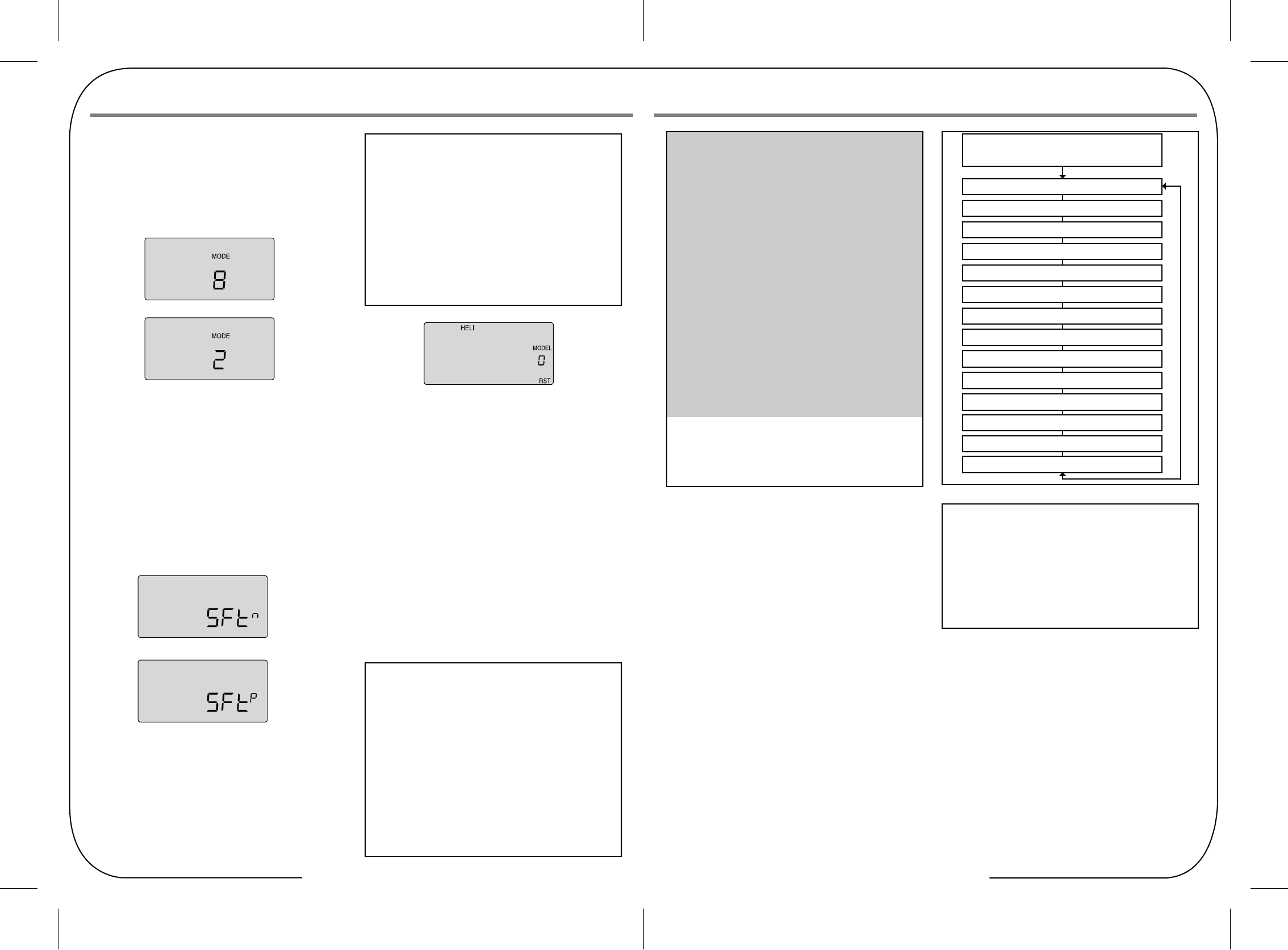
Table of Contents - Page 12 Table of Contents - Page 13
Model Setup Menu Programming for Powered Airplanes (ACRO)
ACRO Functions Map
Simple Aerobatic Aiplane Transmitter Setup 15
EPA End Point Adjust (servo travels) 27
D/R Dual Rates 27
EXP Exponential Settings 28
STRM Subtrim(Netural settings) 28
SREV SERVO Reverse 29
P.MX Programmable Mixer 29
ELVN Elevon mixing(tailless models) 29
FLPN Flaperon(combined flaps & ailerons) 30
VTAL V-tail mixing 30
A->R Rudder Coupling 31
E->F Elevator Flap Mixing 32
CUT Throttle Cut(engine shut off) 33
CAMB Camber(combined flaps & ailerons) 34
FLT.C Flight condition(NOR, ST1, ST2, ST3)
Gear Swich (SW-1) controls receiver CH5
FLT MODE(SW-3)switch Aft = CAMB On
Volage/Timer Display
hormal Display Mode
End Point Adjust [EPA]
Press both Edit Displa
Dual Paste Set [D/R]
Expon ential [EXP]
Sub-Times [S.TRM]
Servo Resbrsing [REV]
Proo.Mik [PMX]
Elevon Mik[ELVN]
Flaperon Mik[FLPN]
V-Tail[VTAL]
Ail->Rud Mix[E-F]
Elev->Flap Mix[E-F]
Thrattle Cut[T.CUT]
Camber[CAMB]
Flapat aadiioii kal atl.atl.atti
To set up the Optic Sport to fly a particular model, you need to
get into the radio's second programming menu: the model setup
menu. In this menu you can program specific control functions;
set servo throw direction; and set the values of servo travel,
exponential rates and dual rates for the particular model you
selected earlier in the initial setup menu.
Go ahead and switch the transmitter on-you are now in the
standard operating screen.
In the upper left-hand corner it will say "ACRO" and to the right
there will be a large number telling you the state of the battery
voltage (such as 7.2 v) and a smaller single-digit number
indicating the model slot the radio is currently opened to.
There will also be a little black box at the bottom of the screen
with the symbol "NOR". This indicates that the system is
currently in the "normal" flight condition mode. Later, we will
show you how to activate the flight condition modes-and it is
here on the screen where you will be told which mode is
currently active.
Now push down both EDIT buttons at the same time.
The following menu items will appear as you scroll down the list
by pushing down the right-hand EDIT button:
The Tip Sheet
When programming a model for the first time, start with
setting servo direction and then activate any mix's needed
like Flaperon, Elevon or Aileron/Rudder.
Next, progress through adjusting subtrim and setting end
point travel of each servo; then set exponential and dual
rate values.
Transmitter Displays and Messages
4. Configure the countdown timer:
Now you are at the TIMER menu item with a number blinking
away at you-its 10 (minutes) by default.
If you want to set a timer value, go to AT DIRECTION for
more information on using the timer function. Otherwise,
move down to the next menu item.
The Tip Sheet
The Optic Sport features a powerful option allowing you to
select between a Negative or Positive signal transmit shift.
This allows you to use any brand of modern FM receiver.
As a general rule, Futaba¢ç receivers are "Negative" shift,
while JR¢ç, Airtronics¢ç and most Multiplex receivers are
all Positive shift.
All models of Hitec receivers have been offered in both
shift versions, while newer Hitec receivers are now
"auto shift selectable" and automatically know what the
shift the transmitter is.
5. Select the control's Mode configuration:
Under the word "MODE", the number "2" is blinking by default.
Go ahead and accept mode 2 by pushing the right-hand EDIT
button to continue to the next screen.
Of course, if you are used to the mode 1 configuration
(elevator on the left stick, throttle on the right), then select
number 1. Other changes to accommodate Mode 1 flyers
must be done to the transmitter.
Please refer to AT DIRECTION for more information.
6. Select the signal shift:
As indicated by the "SFt" symbol on the screen we are now
in the shift selection menu. The blinking default selection is
"n", meaning negative shift.
If your receiver is marked "positive" shift, push one of the
CURSOR buttons so that a "P" starts blinking.
Then scroll to the next screen.
7. Reset Screen:
In this screen you should now see "GLID" in the upper left
hand corner and the number you selected under "MODEL".
You should also see a tiny "RST" blinking in the lower right
hand corner of the screen. This means RESET-and if you
push both DATA buttons at the same time that's exactly what
will happen: You will undo all the initial programming we just
did, returning all the programming to the factory's default
settings!
Now push the Right EDIT button to scroll right back where we
started when we first turned on the transmitter.
We are now done with the initial setup programming of your
aircraft, so switch off the transmitter.
When you switch it on again without holding down both EDIT
buttons the transmitter will open up in the current model slot
(the one we just programmed) with all the initial settings we just
programmed in effect.
The Tip Sheet
At this point you have selected the type of model ACRO,
GLID or HELI, you wish to set-up.
In the manual text that follows, we will review and explain
the Model Setup Menu of the three different model types.
The first is ACRO, followed by GLID, then HELI. All ACRO
features will be described in detail within the ACRO section.
Within the following GLID and HELI sections, only features
exclusive to GLID and HELI programming will be described
in detail.
For those GLID and HELI features common to ACRO,
we will refer you to their description within the ACRO section.
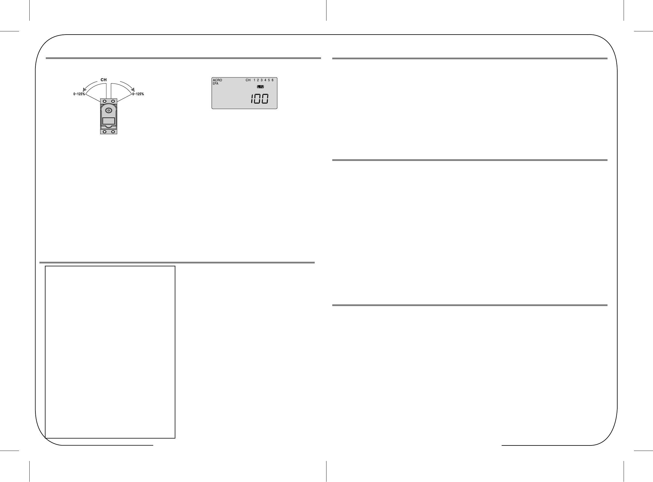
Table of Contents - Page 14 Table of Contents - Page 15
Elevator end points
Throttle end points
Rudder end points
1) To set the UP elevator motion, press on the Right CURSOR
button until CH "2" is flashing.
Now move the right stick all the way toward the transmitter
bottom and hold it. The letters "L/U" should appear above
the percentage value. (Indicating you are setting "U", the
UPWARD motion of the elevator-which also happens to be
the upward movement of the control surface.
Again listen for a buzzing sound to indicate that the servo is
stalling, and hit the -Decrease DATA button until the buzzing
stops. If the servo is not buzzing, leave the setting at 100%.
1) To set the throttle position at IDLE, first return to the regular
display (push both DATA buttons) and push the trim button
to the right of left-hand joystick to set the throttle trim to read
0% on the screen.
2) Then go back to the EPA menu and press the Right
CURSOR button until channel number 3 is blinking.
Now move the throttle stick all the way to the transmitter
bottom and hold it. The letters "L/U" should appear next to
the flashing percent sign. Push the -Decrease DATA button
until the servo moves the throttle plate to a nearly - but not
completely - closed engine idle position. If necessary when
testing the motor, you may increase or decrease the travel
of the servo at idle so you can't accidentally shut off the
engine using the trim tab.
3) To set the FULL throttle position, move the throttle stick all
the way to the transmitter top and hold it. The letters "R/D"
should appear next to the flashing percent sign. Listen for a
buzzing sound to indicate the servo is stalling,
and hit the -Decrease DATA button until the buzzing stops.
If the servo is not buzzing, leave the setting at 100% or
change your linkage as necessary to fully open the throttle.
1) To set the RIGHT rudder motion, press the Right CURSOR
button until the indicator moves over channel 4. Now move
the left stick all the way to the right and hold it.
The letters "R/D" should appear above the percentage value.
Listen for a buzzing sound to indicate the rudder servo is
stalling, and hit the DATA -Decrease button until the buzzing
stops. If the servo is not buzzing, leave the setting at 100%.
You may wish to increase or decrease this number
depending on how strongly the model reacts when the
rudder is deflected.
2) Now move the stick to the left side, and repeat the setting
procedure for left rudder.
Flap (or landing gear) end points
In the same manner as described above, set EPA values for
channel 5 (landing gear or flaps) if your model has these
functions.
2) Repeat the previous step to set the DOWN elevator by
moving the stick all the way toward the top of the transmitter
(R/D will light up). While the elevator is in full down position,
check for binding and buzzing and reduce the travel value as
necessary.
EPA (End Point Adjustment)
Aileron end points
EPA (End Point Adjustment)
The EPA function is used to set (or limit) the travel of each
servo, and may be set anywhere from 0% and 125% for each
travel direction. Reducing the percentage settings reduces the
total servo throw in that direction. The EPA function is normally
used to prevent any servos from binding at the ends of their
travel.
Note: We recommend that before setting end points you first center all
the control surfaces as closely as possible by adjusting the pushrods
or other mechanical linkages between the servos and the horns on the
control surfaces.
Then fine-tune the centering in the sub trim (S TRM) function screen
(see below.)
In this menu function you can set aileron up and down travel,
up and down elevator travels, right and left rudder travels, open
and closed throttle positions, and aileron up and down travels if
you have a second servo for the left wing.
You can also set the end point travel of flaps and landing gear.
Note: If you change the EPA setting to 0%, you will not have any servo
response in that direction, and will probably crash.
When you first enter the EPA menu, you'll see the default
screen as shown.
The CH (channel) "1" right aileron is flashing and the travel
value sits at 100%. Notice that you can change the R/D indicator
symbol above the value to L/U by moving the stick to the left.
You are about to see how this allows you set the travel
directions independently for each stick motion.
Setting up End Points
The Tip Sheet
The following instructions to set aileron end points is based
on an airplane using one aileron servo for both ailerons.
This servo would be plugged into the #1 channel of the
receiver.
IF your airplane uses two aileron servos, one for each
aileron, and you are in the ACRO mode, do the following:
Plug the right wing servo into ch. 1 and the left wing servo
into ch. 6. Activate the Flaperon mix as shown
AT DIRECTION.
Adjust the servo's direction of travel and end points
as necessary.
IF your airplane uses two aileron servos, one for each
aileron, and you are in GLID mode plug the right wing
aileron servo into ch. 1 and the left wing aileron servo into
ch. 5. Activate the ADIF, or aileron differential function as
shown AT DIRECTION.
Adjust the servo's direction of travel and end points as
necessary.
1) To set the RIGHT TURN aileron motion (which is upward on
the right wing and downward on the left wing), move the
aileron stick all the way to the right and hold it.
The right wing's aileron should move upward and the letters
"R/D" should appear above the percent value, meaning you
are setting "R" for Right aileron turn.
2)
If your servo is stalled or binding, you'll hear a buzzing sound.
Hit the minus -Decrease DATA button until the buzzing stops.
If the servo is not buzzing, leave the setting at 100%. If you
can, choose a location for the pushrod on the servo arm so
that the throw is adjusted in the 90-100% range.
3) To set the maximum travel of the LEFT (downward) motion,
move the aileron stick all the way to the left and hold it. The
letters "L/U" should appear above the percent sign (as shown
in the figure above). ("L" is for Left aileron turn). Again listen
and hit the -Decrease DATA button until the buzzing stops.
If the servo is not buzzing, leave the setting at 100%.
16
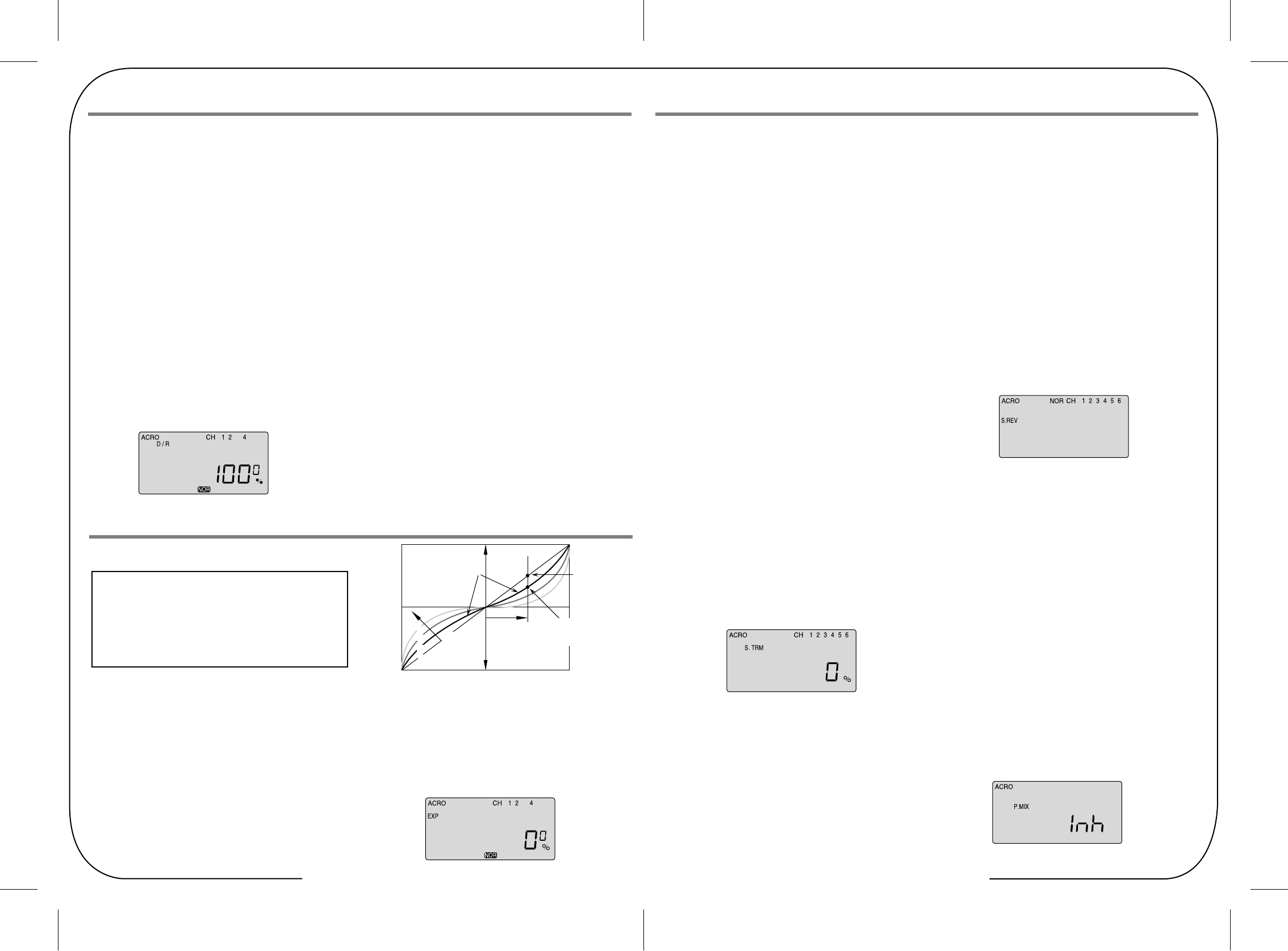
Table of Contents - Page 16 Table of Contents - Page 17
Elevator end points
Setting up exponential
1) Push the CURSOR buttons repeatedly until the channel "1"
is blinking.
2) The default exponential value is 0%. To create some
softness around the neutral position of the stick, we want to
apply some negative exponential. With switch SW-2 set in
the "1" position, push the - DATA button until the screen
indicates -25%--a typical exponential value for ailerons.
You can, of course, increase or decrease this amount as
you get a feeling for how the plane flies.
3) Move over to CH 2 with the CURSOR and set -25% on the
elevator; move to CH 4 and set -25%--again these are
arbitrary starting points subject to your personal preference.
Notice that when you push the SW-2 switch back to its "0"
position all the exponential values return to their default zero
settings.
4) If you want, you can have some "expo" on any or all three
of these channels by setting a value with the switch in the
"0" position. To quickly get back to the default 0%, press the
Clear button.
5) Return to the regular operating mode by pressing the two
EDIT Up Down buttons simultaneously.
Note: You should understand that you won't see changes in your
model's servo response unless you move the sticks.
To get a feel for how exponential works, hold partial stick and watch the
control surfaces as you switch the Expo on and off
(one side of the switch should be set to zero expo in this case).
S TRM (Sub Trim)
This is a programmable function for setting the subtrim values
for each of the servos, allowing you to make fine adjustments
to each individual servo independently of the trim buttons
located on the radio case (which can be adjusted in flight).
We recommend that you first set up the model's servo pushrods
so that the control surfaces are as centered as possible
mechanically (with the transmitter's case-mounted trim buttons
digitally centered) before attempting to adjust them in the s
ubtrim menu. We also recommend that you try to keep all the
subtrim values as small as possible. If the values are large,
the servo's full range of travel may be restricted.
Setting Sub Trims
At this point you must have your plane in front of you and turned
on so you can actually see when the control services are in
alignment as you change the sub-trim value.
1. Starting with the CH 1 aileron servo, use the DATA buttons
to either increase or decrease the subtrim value until the
control surface is properly aligned on the model.
2. Move over to CH 2 with the right-hand CURSOR button and
align the elevator in the same way.
3. Continue by moving to CH 4 and align the rudder, to CH 6 to
adjust the aileron servo in channel 6 and to CH 5 to adjust
the flap.
S REV (Servo Reverse)
When you first turn on your model, you will immediately see
whether all the control surfaces are moving in the correct
direction when you wiggle the controls. If any are moving in
reverse, you can come to this screen to reverse the throw of the
offending servo.
Reversing a servo
Let's say your elevator is going down when you pull back on the
joystick-that is definitely not going to be a good situation when
you go to fly your plane! To reverse the elevator servo, come to
this screen and use a CURSOR button to move over to CH 2
and push both DATA buttons simultaneously.. You'll notice that
the symbol "NOR" ahead of CH has changed to "REV"-and that
the servo is now operating as it should on your model. If any
other servos need to be reversed, CURSOR over to that channel
slot and push both DATA buttons simultaneously.
P MIX (Programmable Mix)
D/R (Dual Rate)
D/R (Dual Rate)
If this is your first computer radio, you may have never been
introduced to dual rates before. Dual rates-which allow you to
reduce the travel of the aileron, elevator and rudder servos
with the flick of one switch (SW-2 on the Optic Sport) are often
used to tone down the control throws when flying at higher
speeds-without this ability, its possible to be really gentle with
the controls and yet still over-control a fast-moving model.
When you flick on a lower throw rate for the servos, you
instantly reduce the radical response of the model to your
control inputs. This ability is a boon for beginning pilots and
very useful even for experts. The amount of travel reduction
(or increase for wild aerobatics!) may be set anywhere between
0 and 125%. Get to the D/R menu by pressing one of the Up
Down EDIT buttons repeatedly until the D/R dual rate screen
appears, as shown.
Note: if you set the dual rate amount to zero, you will get no
response from that channel, which may cause a crash when
you switch to this rate setting..
1. Press the Right CURSOR button to get the channel "1"
blinking (if it isn't already by default): The default value showing
on the screen should be 100%--but notice the extra little zero
next to the 100. This indicates that the rate is this value (100%)
when the switch SW-2 on the upper right hand corner of the
transmitter case is set in the 0 position (check out the label by
this switch). Flick the switch toward you-the number 1 will come
on next to the 100. For now, leave the rate at 100% in the 0
switch position, but let's change the rate for CH 1 when you
move the switch to 1.
2. With the switch SW-2 forward and "1" showing next to the
default 100 value, reduce the value to 75% by pushing down
on the - DATA button. Now whenever you move switch SW-2
to the 1 position, the travel of the ailerons (note that the second
aileron is automatically affected) will be 75% of the "normal"
100% value. When flying the plane you will quickly see if 75%
is enough of a reduction-if not, you can always come back and
change it in this screen. (This is true, or course, for all the
parameters we are going to establish in this menu set).
Note: If you quickly want to get back to the default 100%,
press the Clear button
EXP (Exponential)
The Tip Sheet
Exponential ("Expo") is great for beginners and highly
recommended. Try it out. Your flying will be smoother and
more controllable, reducing the stress most beginners feel
when learning to fly.
This function-which may also be new to first-time computerized
radio users-allows you to choose the exponential value for the
ailerons, elevator and rudder. Applying exponential enables
you to "soften" the stick throws to take out the "twitchiness" of
your model's response to your control inputs.
The greater the negative value you specify, the less effect the
sticks have around their center points-and the less effect your
twitchy fingers have on your model's performance. (Conversely,
positive exponential makes the servos very sensitive around
neutral and soft at the extreme stick throws-an effect best left
to the experts!) Like the dual-rate programming, you can apply
or remove this function with switch SW-2.
Note: The values you set for exponential are highly dependent
on both the model and pilot's preference.
We recommend a start value of about -25 to -35%, and, after
test flying, slowly increasing the number until things feel "right".
Obviously this depends on the pilot and model so go ahead and
fly it with Expo only on one side of the switch, turn it on and off
during flight, and change the values to suit yourself.
Or don't use it at all if you don't like it - it's not for everyone.
Servo
Response
Stick Motion Exponential gives
smaller response for
same stick motion
around neutral
Normal
linear
response
Increasing
exponential
(shallower around
neutral)
0%
(Linear)
25%
50%
75%
Much less response
around neutral(compare
with Normal line)
Table of Contents - Page 18 Table of Contents - Page 19
ELVN (Elevon mix)
ELVN (Elevon mix)
front view
If you are setting up a tail-less delta or flying wing aircraft, you
can use this program to activate the pre-programmed elevon
mix that mixes the output on the CH 1 aileron and CH 2 elevator
servo channels. (As you will notice in the servo connection
chart, you plug one aileron servo in the receiver's channel 1 slot
and the other aileron servo into channel 2-the slot that usually
feeds the elevator.) This is necessary because on these wing
types the ailerons must double as elevators.
Note: When you activate ELVN, note that flaperon and V-tail
mixing are rendered unavailable by the radio.
2) Now set the amount (and direction if necessary as noted a
bove) of each servo-both as ailerons and as elevators.
Because flying wings are extraordinarily pitch sensitive
(because the elevator control surface is so close to the
airframe's center of gravity), you generally need the elevator
travel to be much less than that of the ailerons.
We create this type of differential in the next step.
3) For now, leave the "MAS 1" percentage value at the default
100% (unless your servo is stalling) and then CURSOR over
to the "SLV 1" where you will also leave the default value at
100%. Push the CURSOR button again to light up "MAS 2"
and reduce the value to +40%; CURSOR over to "SLV 2"
and reduce that value to +40% as well.
If one of the servo's travel directions isn't correct in the
elevator function, simply make this servo's travel volume a
negative -40%.
4) When you fly the model, if you find that this 40% reduction
isn't enough to take out "pitchiness", land and further reduce
the travel volume. To tone down the roll response, you can
reduce the endpoints of the aileron travel or set up dual-rates
on channel one as described in the setup of Model-1 above.
[Insert graphic of aileron differential and flaperons function]
This function activates another aileron servo (on channel 6
when in the ACRO menu) so that both ailerons can be slaved
together to create a flaperon. This allows both ailerons to move
together as flaperons for camber control or independently as
usual for roll control. In this menu you can also set individual
travel values-upward and downward-for each aileron to create
aileron differential. Being able to move an aileron less in one
direction (usually downwards) helps reduce yaw in turns
(and therefore unnecessary drag.)
FLPN (Flaperon)
Setting up elevons
1) Activate the elevon function by pressing both DATA buttons
when you are in the ELVN screen. Now check your model to
see what happens when you move the right-hand joystick
side-to-side-the ailerons should go up and down appropriately.
Move the joystick forward and back to see if the ailerons both
respond correctly as elevators. If necessary, go to the S REV
screen to reverse an offending servo.
IMPORTANT NOTE: It is possible due to the particular
configuration of your servos that servo reverse won't fix the
problem-you may get the ailerons working properly but not the
elevator response on both servos.
Don't worry: You can fix this problem in the elevon programming
by changing one of the servo travel volumes to a negative value.
CH1 CH2
Aileron Operation
Elevator Operation
P MIX (Programmable Mix)
In this screen you can activate the ability of the Optic 6 Sport to
create a custom-made, programmable mix of any two servo
channels in which one servo is electronically "slaved" to another.
This is a relatively advanced function.
The program also provides a way to change the value of the
response of the slave servo to that of the master.
For example you could slave the elevator servo to the throttle
channel so that when you increase the throttle, a slight
downward movement of the elevator kicks in to automatically
compensate for any up-pitching due to the increased thrust.
Another typical mix might be to mix rudder with the throttle to
reduce yawing. The Optic Sport's mixing program also offers an
advanced function (call TRM P MIX) that, when activated,
allows both servos to be trimmed by the same master servo
trim button on the radio case-a useful option when, for example,
you are using two servos to control a split elevator.
We will show you how to set up these examples below.
Set up a throttle-to-rudder mix
When you apply throttle to a powerful motor, the resultant
torque from the spinning propeller often tends to make the
plane yaw to one side (usually to the left).
This not only interferes with precision aerobatic maneuvers,
but it makes it difficult to keep the model aligned with the
runway during a full-power takeoff. To reduce the "pilot load"
of having to correct the yaw with your left thumb on the rudder
stick, you can use the P-Mix program function to automatically
mix a proportional amount of rudder with an increase of throttle.
Now let's set it up:
shows "CH" with "MAS" blinking beneath. If, instead,
a percentage value is blinking use the right-hand CURSOR
button to scroll over until you get this "CH" and "MAS"
configuration. One of the servo channel numbers will also be
showing-the default is "1".
2) To make the throttle the master channel, push a DATA
button to light up "3". Now push the right-hand CURSOR once
more: "SLV" will light up with a number. Use a DATA button to
change this number to "4". Now the rudder channel is slaved
to the throttle channel.
3) Push the CURSOR button again: MAS 3 and a percentage
value will be blinking. Use the DATA buttons to set the value
of rudder travel to throttle travel-change to a negative value to
move the rudder in the opposite direction if necessary.
You won't likely need more than 15% to counteract the torque,
but only flight-testing will tell for sure.
1) Enter the Main Function menu and scroll down to the P MIX
screen with the EDIT buttons. Activate the function by pressing
both DATA buttons-"Inh" will turn off and the default screen
P-Mix trim:
Set up a double-servo elevator with coordinated trim function
The Optic 6 Sport offers an unusually sophisticated nuance
with its P-MIX function: the ability to trim two servos
simultaneously. This is especially useful if you are using two
elevator servos (one to each half of the elevator). In flight,
if the elevator needs to be trimmed, you can make the
adjustment with the trim button next to the right-hand joystick
on the case instead of having to enter the model setup
programming in order to trim the servos independently.
Lets set this example up:
1) Enter the P MIX screen and select the master and slave
servos (2 and 5 on this radio for split elevators) and then select
the travel value (most likely 100% unless your servo pushrods
are not set up exactly the same way).
2) Now use the Right CURSOR button to move to the P MIX
screen where "TRM" is blinking. The default setting is
"OFF"-turn it to "ON" by pressing the CLEAR button.
3) Exit the menu and you now have a split elevator with trim
function.
Table of Contents - Page 20 Table of Contents - Page 21
ELVN (Elevon mix)
Setting up a V-Tail
1) Activate the program by pushing down both DATA buttons
simultaneously-the screen will change from "Inh" to a % value.
2) With your model turned on, check your servo travel
directions-both rudder and elevator channels-to be sure they
are correct. Go to the S REV screen if necessary to make the
correction.
3) For a basic V-tail setup, you can leave all the values at 100%
so that the tails will move together as an elevator, but not
independently as rudders.
4) If you wish to add rudder control to help coordinate the turns,
proceed this way: CURSOR over until MAS 4 is blinking than
change the value as necessary (you may have to go into
negative values) to make the master servo on channel
4 move appropriately (see the illustration AT DIRECTION).
Now CURSOR over to SLV 4 and change the value of the
slave servo on channel 2 as necessary.
Setting up a rudder-to-aileron mix
1) In the A-R screen, activate the function by pressing both
DATA buttons at once. The "Inh" symbol disappears and is
replaced with a percentage value (100% is the default).
2) Hold the right-hand joystick to the left, and use the - DATA
button to reduce the value to a reasonable mix to begin with,
say 25%.
3) You're not done yet, though-we have the same issue with
the stick we encountered in the end point adjustment (EPA)
screen.
If you move the aileron joystick to the right, the value goes
back to the default 100% setting. Hold the stick to the right
and reduce the value to 25% here as well.
4) Now watch the rudder move as you move the joystick right
and left-as the right wing's aileron moves up, the rudder
should swing about one-quarter of its travel to the right-and
to the left with left-hand stick travel.
The optimum value of the mix can only be determined by flying
the model: If the nose of the airplane yaws to the right when
you bank left, there is too little coupling-increase the rudder
travel value. If it veers to the left (with the bank) there is too
much
This program allows you to set a certain amount of
elevator-to-flap mixing so that the flaps (or flaperons if you've
activated this mix) move downward slightly when you pull back
on the elevator stick. This is a favorite mix for pylon racing and
3-D aerobatics as a downward flap movement combined with
up-elevator movement enables the plane to snap-turn more
quickly.
E-F (Elevator-Flap mix)
A-R (Aileron-Rudder mix)
This pre-programmed aileron-rudder mix allows you to slave a
certain amount of rudder movement with the movement of the
ailerons to gain automatically coordinated turns. In addition to
aileron differential, this mix reduces the yawing of the fuselage
when the ailerons bank the wing.
This mix is especially useful for making the turns of slower-flying
scale models appear more realistic.
UP elevator
DOWN flap or flaperon
P MIX (Programmable Mix)
Setting up flaperons
1) Activate the program by pushing both DATA buttons-the
"Inh" symbol changes to the default 100% value. With your
model turned on, test the ailerons by moving the joystick to
the right and to the left: To the right, the right-hand aileron
should go up while the left-hand aileron goes down.
If this isn't happening, go to the S REV screen and reverse
the offending aileron.
2) Now check the travel volume: If the servos are stalling at
their maximum throw, turn down the value in the EPA screen
(or move the pushrod further up on the aileron horn to
physically reduce the throw).
Create aileron differential
Now let's create some aileron differential so that the ailerons
move about twice as much upward than downward.
Notice that the "MAS" (master) symbol is blinking along with
channel 1 and the % sign. This means that we can change the
travel value of the right-hand aileron (the master servo).
Also notice that L/U is showing, meaning the value will change
only for left-stick throw.
1) Reduce the downward movement to 50% by pushing down
the left-hand DATA button. Now move the stick to the right
and you will see R/D appear along with the default 100%
throw value.
2) To create similar differential on the left hand servo
(the slave) push down the right-hand CURSOR button
once-now the "1" and the "SLV" symbols will be blinking.
This time leave the L/U stick position at 100%, then move
the stick to the right to light up R/D and decrease the
downward travel value to 50% with the left-hand -DATA
button.
Now we have differential-each aileron should be moving
downward about half the amount it moves upward.
You will likely have to adjust these values once you fly the
plane and observe the yaw of the fuselage as you roll the
aircraft:
This is another built-in mixing program available in the Optic
Sport that mixes the rudder and elevator servos for controlling
V-tailed aircraft. Similar to elevon programming, the two
surfaces can move up and down together (for elevator control)
or opposite (for rudder control in this case).
Note: When you select V.TAL, the ELVN program is rendered
unavailable.
V TAL (V-Tail)
[Insert V-Tail illustration]
Nose Points outside Circle
increase coupling and/or
differential
Coordinated turn
fuse lines up with turn direction
(don't change anything!)
Nose Points inside circle
Too much coupling or differential.
Reduce one or both.
CH2 CH4 CH2 CH4
Up Elevator Right Rudder (view from rear)
Table of Contents - Page 22 Table of Contents - Page 23
ELVN (Elevon mix)
6. To set a bit of downward compensation in the elevator travel
(we are assuming your airplane will likely nose upward when
the camber is activated), CURSOR over to channel 5 and set
15% of downward deflection.
IMPORTANT NOTE: If you turn on your radio with one
(or more) of the switches turned on to an activated flight
condition, the radio will start beeping at you and the screen will
inform you which switch is on. If this happens don't panic: simply
move the switch(s) until the beeping stops and the "NOR"
symbol appears.
Setting up flight condition modes
1. Move both mode switches to their normal positions: SW-1
toward the back "0" and SW-3 to the middle).
2. To activate a flight mode on switch SW-1 move the switch
position toward you to "1" and hit both DATA buttons
simultaneously. The "Inh" symbol will change to "On" and
ST3 will be blinking. Now move the switch back to the "0"
position.
3. To activate two more flight modes, move switch SW-3 from
its center position (NOR) toward the back of the transmitter.
Activate the mode ST1 by hitting both DATA buttons
simultaneously. The "Inh" symbol will change to "On" and
ST1 will be flashing.
4. Move switch SW-3 to the front of the transmitter. Activate
the mode ST2 by hitting both DATA buttons simultaneously.
The "Inh" symbol will change to "On" and ST2 will be flashing.
5. The middle position, normal (NOR), is by default the fourth
flight mode.
To activate a certain flight mode condition while in flight, simply
move the appropriate switch. Note that SW-1 over-rides SW-3
in any of its three positions
Setting up flight condition modes with different dual rate and
exponential values
Let's set up two dual-rate and exponential settings in addition to
those established with the switch SW-3 in the center, normal
(NOR) position. We'll assume that you have already activated
modes ST1 and ST2 on this switch as instructed above:
1. Enter the Main Function menu by pressing both EDIT buttons
with the transmitter on.
2. Scroll to the dual rate (D/R) screen with the Right EDIT button:
CH 1 should be flashing and "NOR" should appear at the
bottom of the screen under the default value of 100%.
(If it isn't, you can return to the default value immediately by
pressing the Clear button). Next to the 100%, a "0" indicates
that switch SW-2 is in the 0 position-if it isn't, put it there.
3. Using one of the DATA buttons, enter a rate value for the
ailerons in CH 1-then move switch SW-2 to the "1" position
and enter another value. This will be the dual-rate range for
the ailerons in the normal (NOR) flight mode.
As always, you will likely have to change all these values
somewhat when you get the model up into the air.
FLT C (Flight Conditions)
This is a sophisticated function of the Optic 6 Sport's
programming that allows you to activate up to four different
flight condition modes with switches SW-1 and SW-3. In these
modes you can select four different amounts of dual-rate,
exponential and flaperon and elevator settings for each switch
position.
We already demonstrated this function above when we set up
one additional flight mode with camber settings. Having the
ability to set up four flight modes with different dual-rate and
exponential functions offers some useful nuances of flight
control when you are flying in changing weather conditions or
performing advanced aerobatics.
P MIX (Programmable Mix)
Setting up an Elevator-to-Flap mix
1. In the E-F screen, activate the function by pressing both
DATA buttons simultaneously. The "Inh" symbol disappears
and is replaced with a percentage value (100% is the default).
2. Now hold the right-hand joystick all the way back (for full up
elevator) and then, as you watch your model, change the
value to gain the amount of down-flap movement you want
at full up-elevator. You probably won't need more than 15%,
but only in-flight testing will tell you for sure.
3. Finally, push the stick forward and reduce the value to
0 %-you generally don't want the flaps going up when you
push the elevator stick forward.
This program allows you to initiate a mixing of the ailerons with
the flaps to camber the wings a certain distance downward.
Camber changes the airfoil to create more lift as you slow the
aircraft down for landing or to make a scale model fly more
slowly and realistically. You will also be able to set the travel of
the elevator on this menu screen to compensate for the model's
tendency to nose up when the flaps and ailerons droop down
together.
Setting up wing camber and elevator compensation
1. To use the ailerons as flaperons to slightly droop down in
unison to camber the wing we first need to get into the FLT C
screen in order to put the flaperons action on the
three-position SW-3 "FLT Mode" switch on the upper
right-hand top of the transmitter case. Use the right-hand
EDIT button to move down to the FLT C screen.
2. Start with the SW-3 switch in the middle position.
Now move it toward the front of the case and you'll notice
that the "Inh" symbol comes on and the "NOR" symbol in the
black box changes to "ST-2". Activate this switch position by
pushing both DATA buttons simultaneously.
Now we are ready to feed in values for the ailerons and
elevator (for pitch compensation) when you pull the switch
toward you. (You could, of course, choose to activate the
mode with the switch pushed all the way back (ST 1) if that is
more intuitive for you.)
3. Move back up one screen with the EDIT button to the CAMB
screen.
4. With the SW-3 in the middle, "NOR" position, check to be
sure that the values for channels 1, 2 and 6 all read 0%.
Now pull the switch toward you-"ST 2" appears instead of
"NOR"-and use a DATA button to set the downward travel
value for the right-hand aileron to 25% (+ or - depending on
your servo orientation.)
5. CURSOR over to channel 6 and set the left-hand aileron to
deflect 25% down as well.
CAMB (Wing camber)
CUT (Engine Cut function)
In this screen you can set the throttle's servo travel value
(you can also choose the direction in the program) so that you
can immediately cut off the motor when the engine is below
half throttle with a push of the "Eng Cut" button located on the
upper right-hand corner of the transmitter case.
Setting the engine cut function
1) In the "CUT" screen, un-inhibit the program by pushing both
DATA buttons-a percentage value comes up on the screen
(default is 0%).
2) Use either DATA button to change the value to a setting
(you can go positive or negative up to 50%) that moves your
throttle servo to the point where its pushrod fully closes the
motor's carburetor. (You activate the servo cut movement by
pushing the "ENG CUT" button on the upper right portion of
the transmitter case.)
3) Watch the servo movement on your model carefully:
You don't want to overdo the travel value or you'll stall the
servo (you'll probably hear it buzzing if its stalled-which
creates a drain on the on-board battery and a potential
over-heating problem for the servo).
Table of Contents - Page 24 Table of Contents - Page 25
Sailplane Controls and Switch Assignments
P MIX (Programmable Mix)
Model Setup Menu Programming for Sailplanes (GLID)
4. To establish a second set of dual rates for the ailerons in
flight condition mode ST1, move the switch SW-3 to the back
of the case: ST1 appears. Now set a dual rate when the
switch SW-2 in the "0" position and then in the "1" position.
5. To establish a third set of dual rates for the ailerons in flight
condition mode ST2, move the switch SW-3 to the front of the
case: ST2 appears. Now set a dual rate when the switch
SW-2 in the "0" position and then in the "1" position.
To avoid duplication of text within the manual we suggest that
if you have not already read the following you refer to this
previously shown information in the front of the manual.
Introducing the Optic Sport
If you are new to Computerized RC Transmitters
Charging the Batteries
Flying Safely
Mode 1 Configuration
Flying Field info
Frequency Control
Optic Sport Programming Switches and Buttons
Optic Sport In-Flight Controls
Transmitter Displays and Messages
Initial Setup Menu Programming
6. If you wish to set dual-rate ranges for the elevator and the
rudder follow the last three steps above-entering in the values
in elevator CH 2 and then in rudder CH 4.
7. To establish the two additional flight mode exponential
settings, scroll to the EXP screen and follow essentially the
same process outlined above for setting the dual-rate ranges.
(Note that both the dual-rate and exponential settings are
toggled on the same switch: SW-2).
GLID FUNCTIONS MAP
Simple Aerobatic Aiplane Transmitter Setup 15
EPA End Point Adjust (servo travels) 27
D/R Dual Rates 27
EXP Exponential Settings 28
STRM Subtrim(Netural settings) 28
SREV SERVO Reverse 29
P.MX Programmable Mixer 29
ELVN Elevon mixing(tailless models) 29
FLPN Flaperon(combined flaps & ailerons) 30
VTAL V-tail mixing 30
A->R Rudder Coupling 31
E->F Elevator Flap Mixing 32
CUT Throttle Cut(engine shut off) 33
CAMB Camber(combined flaps & ailerons) 34
FLT.C Flight condition(NOR, ST1, ST2, ST3)
Gear Swich (SW-1) controls receiver CH5
FLT MODE(SW-3)switch Aft = CAMB On
Volage/Timer Display
hormal Display Mode
End Point Adjust [EPA]
Press both Edit Displa
Dual Paste Set [D/R]
Expon ential [EXP]
Sub-Times [S.TRM]
Servo Resbrsing [REV]
Proo.Mik [PMX]
Elevon Mik[ELVN]
Flaperon Mik[FLPN]
V-Tail[VTAL]
Ail->Rud Mix[E-F]
Elev->Flap Mix[E-F]
Thrattle Cut[T.CUT]
Camber[CAMB]
Flapat aadiioii kal atl.atl.atti
Trainer or
engine Cut
Switch
SW 2
Aileron Dual
Elevator
Rudder
Dual Rate Switch
SW 1
Crow Mix or
Throttle switch
Rudder &
Throttle Stick
or Crow Mix
Aileron &
Elevator Stick
Throttle
Trim Switch
Elevator
Trim Switch
Rudder
Trim Switch
Aileron
Trim Switch
Power Switch
SW 3
Flight Mode
Switch
This figure shows the assignments for a Mode 2 system as supplied by the factory.
Note that some of the functions will not operate until activated in the mixing menus.
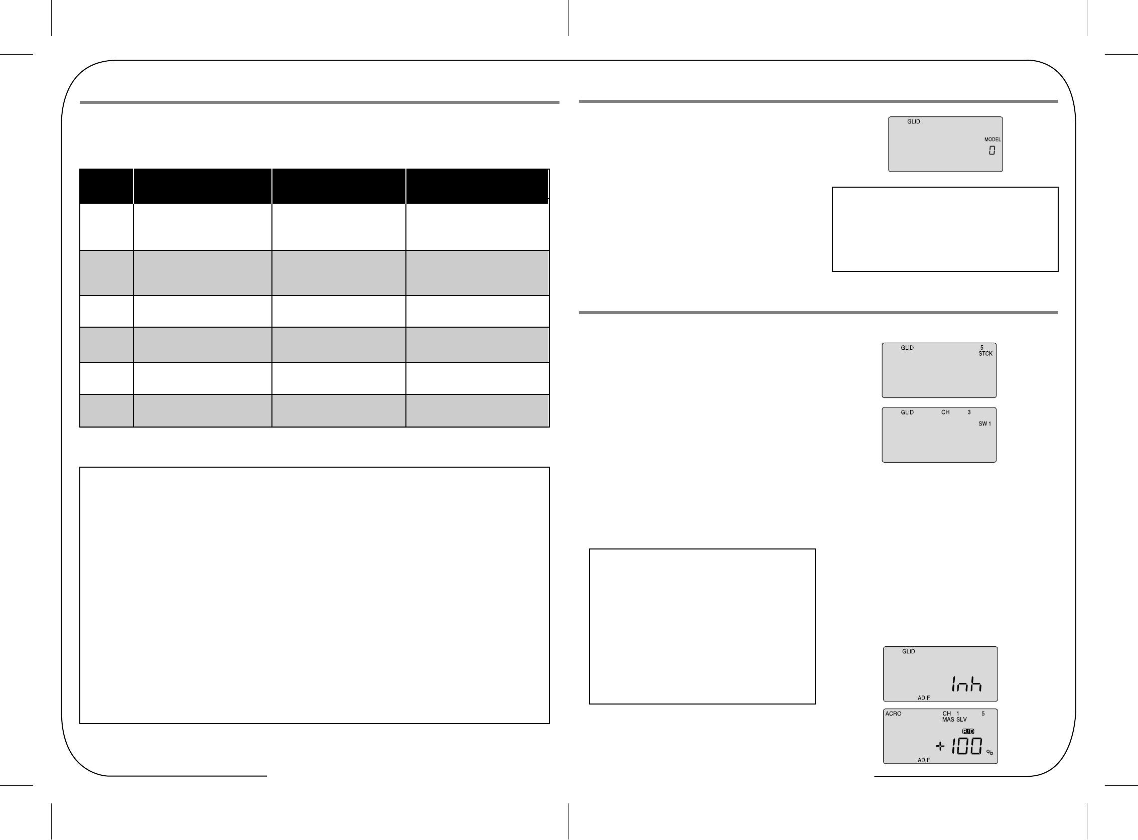
Table of Contents - Page 26 Table of Contents - Page 27
Initial Menu feature review for GLID programming
Model Setup Main Menu Programming
The following item is located in the Initial Menu as described
on page XX. We will review it here
Select the Model type baseline: In the second menu screen,
the programming baseline of ACRO, GLID, or HELI will be
blinking. Since we are setting up a Sailplane, select GLID by
scrolling to it with a CURSOR button.
Push down both DATA buttons simultaneously to tell the
program to accept the choice-you should hear the transmitter
beep twice in acknowledgement.
This section covers the Optic Sport's "GLID" mode that allows
you to program functions specific to sailplanes.
Please refer to the Initial Setup menu on page XX, and the
ACRO Main Function menu starting on page XX. to reference
all other Optic Sport programming instructions not specific to
the GLID menu.
In the GLID programming baseline three new functions appear
that are not available in the ACRO mode: A CROW function
allows you to program a descent control in which both ailerons
move upward while the flaps move downward; an ADF function
creates flaperons and aileron differential and a STCK function
moves the throttle of your glider's motor off the left-hand joystick
and places it on the switch SW-1 on the upper left-hand corner
of the transmitter case (which frees up the joystick to
proportionally control the "crow" function.)
STCK (Throttle stick or switch)
ADIF (Aileron differential)
If your glider uses an electric motor for self-launching, the GLID
programming baseline thoughtfully allows you to retain throttle
control even if you opt to activate the Crow function on the
left-hand joystick/throttle stick. To make this change in order to
have a proportional Crow function, follow these two steps:
1. Go into the Main menu and scroll down to the STCK screen.
The default setting puts the throttle on the left-hand joystick.
2. To put the throttle on the switch SW-1, push down both
DATA buttons simultaneously and watch as the screen
displays "SW 1". Now, when you move this switch toward
you from "0" to "1", the motor will come on with full power
Important Note: Do you have a "flying wing" glider?
In the GLID mode the ELVN program is rendered
unavailable-if your glider is a flying wing, use the ACRO
mode to set it up.
The Tip Sheet
At this point you should have selected GLID in the Initial
Setup Menu as the baseline programming for the model
you wish to set-up. In the text that follows, we will review
and explain the Model Setup Menu items specific to the
GLID Menu for setting up your glider.
For those GLID features common to ACRO, refer to their
description within the ACRO section to set up your model's
basic functions (such as servo reverse and end point travel).
Servo Connection List
Receiver
channel
1 Aileron
or Right Flaperon(FLPN on) Aileron Aileron(or Ropll Cyclic)
or Right elevon(ELVN on) or Right Aileron(ADIF on) or Swash servo 1(120¡Æ)
2 Elevator
or V-tail right side(VTAL on) Elevator Elevator (or Pitch Cyclic)
or Left elevon(ELVN on) or V-tail right side(VTAL on) or Swash servo 2 (120¡Æ)
3 Throttle Throttle(controlled by throttle Throttle
stick or Switch 01)
4 Rudder or Rudder or Rudder
V-tail left side(VTAL on) V-tail left side(VTAL on) (Or Yaw control through the gyro)
5 Landing gear (controlled by Gyro sensitivity
GEAR/FLT.MODE ST-3 switch) Left aileron (ADIF on) (values set in GYRO menu)
6 Flap or Pitch (or Collective)
Left flaperon(FLPN on) Flap or Swash servo 3(120¡Æ)
The Tip Sheet If this is your first Sailplane...
If this is your first model Sailplane, here are a few tips that will streamline your experience in programming it.
This will make more sense after you read through the manual. Refer back to this section when you are ready to begin the setup:
1. Start with the correct model type, GLID, in the Initial Setup Menu.
2. Access the main programming menu, then use the REV function, and make sure all the servos are moving in the proper
direction.
3. After centering the servo arms manually as close as you can, use the S.TRM or sub-trim function to center the servos.
4. Set your servo end points with the EPA function.
5. Program -35% EXPO values for aileron, Ch. 1 and elevator, Ch. 2.
6. After your Sailplane is all ready to fly, put it on a shelf and go get an R/C flight simulator program for your PC. Spend quality
time crashing the virtual plane in the simulator. Using a sim will save you hundreds of dollars spent on spare parts and
countless hours of rebuilding time in the long run.
7. Ready to fly your new Sailplane? If you are lucky you will know someone that is an experienced model pilot and would be
willing to check over your plane and take it up for its first flight. This is HIGHLY RECOMMENDED, even if you have to drive a
hundred miles to get to this person! If you are on your own, start slow and conservatively.
Aircraft(ACRO) Glider(GLID) Helicopter(HELI)
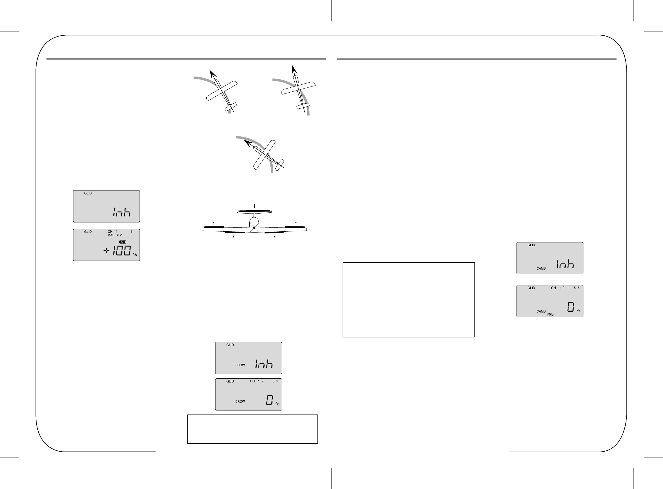
Table of Contents - Page 28 Table of Contents - Page 29
Initial Menu feature review for GLID programming
Setting up Crow
Setting up flight mode wing camber and elevator compensation
CAMB (Wing camber)
1) Activate the function by pressing both DATA buttons
simultaneously.
2) Watching the motion of the control surfaces on your model,
set the value for each of the servos with the left-hand joystick
pulled all the way to the bottom of the transmitter case.
Begin with the aileron servos in CH 1 and CH 5: Unless the
servos buzz and stall, set both ailerons to the default 100%
upward (Note that you can go to a negative value % to
reverse the direction of the movement of one of the aileron
servos if necessary).
3) Set the flap servo on CH 6 to 100% full down (If you have
two flap servos, they should be connected with a Y-harness
to the channel 6 slot on the receiver).
4) Finally, curser to CH 2 and set the elevator travel value so
the elevator moves down just a bit for pitch control: 15% is a
good starting point, though in-flight testing is necessary for
making true, final adjustments.
Launch: When switch SW-3 is pulled toward you the ailerons
and flaps will rise together slightly to "reflex" the airfoil for
high-speed flight and the elevator will kick up a few degrees to
rotate the model vertical in the first 5 seconds or so of flight.
Cruise: When you push switch SW-3 to the middle position,
the ailerons and flaps will come even with the trailing edge and
the elevator will move down very slightly (relative to its normal
angle of incidence). This allows the glider to quickly fly between
thermals and through areas of sink.
Thermal: With the SW-3 switch pushed away from you,
the ailerons and flaps will droop down 3/6-in. and the elevator
will come up a few degrees from its normal angle of incidence.
This is the mode to be in when you suspect you have hooked
into a thermal. The glider is now at its lowest sink rate and can
fly just above a stall to allow you to turn tightly and keep in the
small core of the thermal.
1. The first step is to leave this screen and move down to the
Flight Condition (FLT C) screen in order to put the wing
camber and elevator action of each mode on the
three-position SW-3 "FLT Mode" switch on the upper
right-hand top of the transmitter case. Use the Right EDIT
button to move down to the FLT C screen.
2. Now activate what will be the "launch" mode by moving the
switch position toward you and then hitting both DATA buttons.
The "Inh" symbol will change to "On" and ST2 will be blinking.
Move the switch all the way back and, in the same way,
activate switch position ST1 which will become our "thermal"
mode. The middle, normal position (NOR) is "cruise". You can,
of course, reverse the launch and thermal positions to what
feels intuitive to you.
The Tip Sheet
While the Camber function also appears in the ACRO menu,
the use of this feature is significantly different for Sailplanes
than it is with Power planes. Please refer to the instructions
below to understand how to make the most effective use of
Camber on your Sailplane.
A solid understanding of the Flight condition feature will help
when programming wing Camber.
When flying gliders featuring modern, thin airfoils the ability to
change the shape of the airfoil by reflexing (raising) or
cambering (lowering) the trailing edge in combination with
making simultaneous, slight changes in elevator trim is crucial
to optimizing the performance of the model in a variety of flight
conditions and tasks. The Optic Sport offers a selection of up
to four flight condition modes in which you can program varying
amounts of aileron, flap and elevator trim (as well as dual-rate
and exponential values). These modes are activated by either
switch SW-3 or SW-1.
A typical example for setting up a discus-launched glider for
optimum performance would consist of these three flight modes
(which are all assigned to SW-3):
SAFETY WARNING: When checking out the in-flight response
of your model to the crow settings, be sure to first gain at least
200 feet of altitude to allow time for you to recover from any
loss of control.
Servo Connection List
Activating Flaperons
CROW (Glide-path and airspeed control)
(Crow raises the ailerons and lowers the flaps when you move
the left-hand joystick toward the bottom of the transmitter case)
In this screen you can activate the Crow air-brake and glide
path control function and set the values for the aileron, flap and
elevator servo movements. The more Crow you apply during
the landing approach (with the left-hand joystick), the more the
glide path steepens and the glider slows down. Because you
can regulate the amount of crow, you can precisely control
where and how slowly the glider lands-an important factor for
landing on limited-length runways (gliders are generally a lot
more "slippery" than power planes!) and in contests where you
are rewarded points for landing on a target.
The Tip Sheet
You must have A.DIF activated for ch. 5 to appear on the
CROW screen
Creating aileron differential
Now let's reduce the downward travel of each aileron to about
half that of the upward travel (a good starting point for setting
up differential on a typical sailplane:
1. Be sure MAS and "1" are blinking. Now, as you hold the stick
to the left, reduce the value with the -DATA button to 50%.
2. Use the Right CURSOR to get "SLV 1" blinking and then
reduce the travel value to 50% as you hold the stick to the
right. Now your ailerons are programmed with 50% differential.
This is the Main Function Menu screen (instead of FLPN in the
ACRO baseline) where you can activate the aileron servo
plugged into channel 5 to create flaperons. It is also where you
can create aileron differential: Being able to adjust the ailerons
so they can travel more in one direction (usually about twice as
much UP movement as DOWN) is an especially important
quality for sailplanes as differential reduces the "parasitic" drag
due to a yawing fuselage and to unnecessary aileron travel.
Using the right-hand EDIT button, scroll down to the ADIF
screen and activate the differential programming by pressing
both DATA buttons. The "MAS" and CH "1" should now be
blinking and CH 5 "SLV" holding steady (indicating the master
servo is channel one and its slave is channel 5).
The default values for both left-hand stick throw (L/U) and
right-hand stick (R/D) should be 100%. Now, when the right
wing's aileron moves up and down with the stick throw, the
left-wing aileron follows suit (but in the opposite direction).
If you activate the Crow function and/or the Elevator-to-Flap
mix, both ailerons will move in unison as Flaperons.
Note: You must activate this program to create flaperons before you
can set up Elevator-to-Flap, Camber, or Crow mixing functions.
Nose Points outside Circle
increase coupling and/or
differential
Coordinated turn
fuse lines up with turn direction
(don't change anything!)
Nose Points inside circle
Too much coupling or differential.
Reduce one or both.
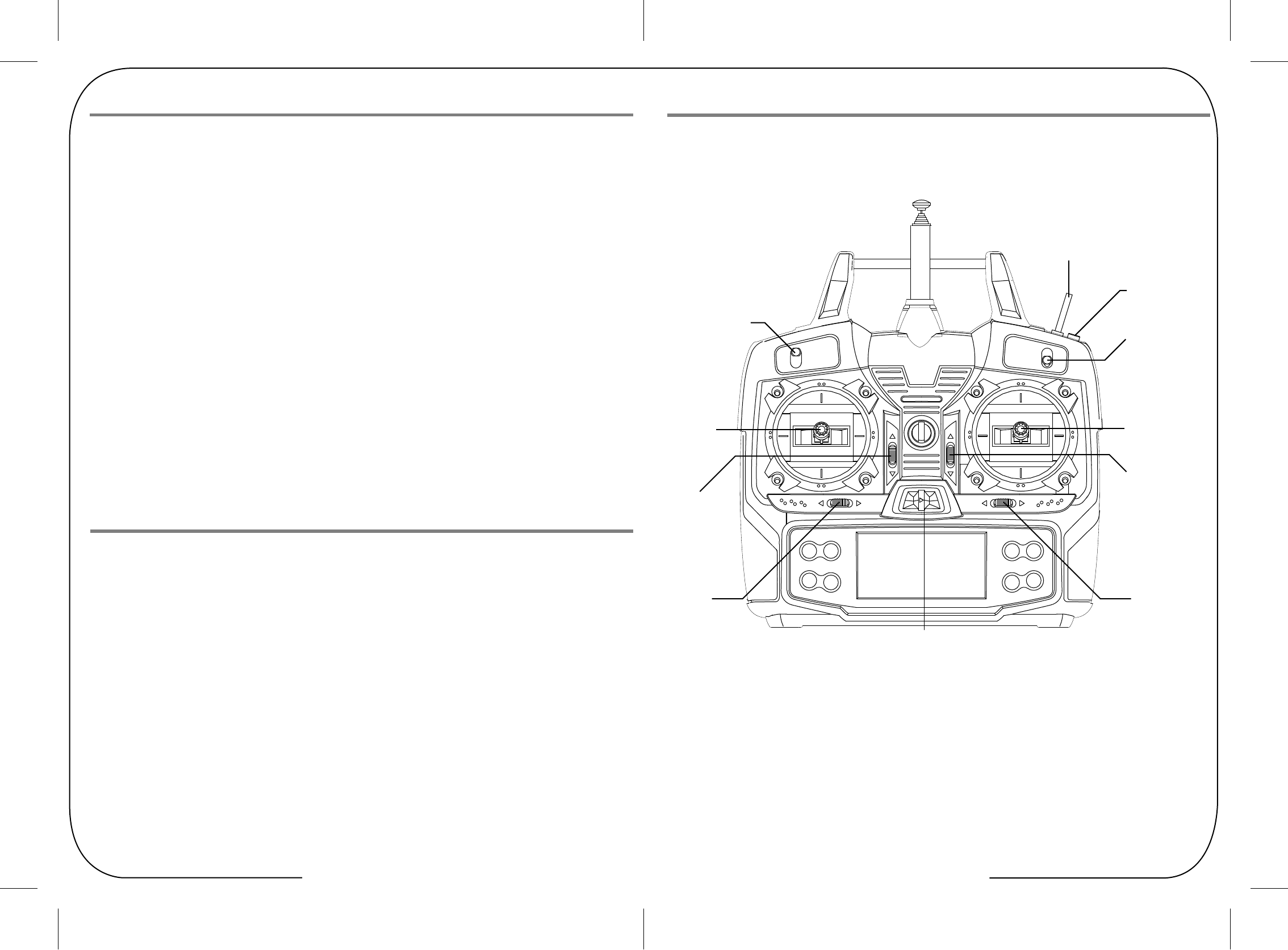
Table of Contents - Page 30 Table of Contents - Page 31
Helicopter Controls and Switch Assignments
Optic Sport Manual for Helicopters
This section covers the Optic Sport programming that is specific to the HELI mode for flying a model Helicopter.
To avoid duplication of text within the manual we suggest that if you have not already read the following you refer to this previously
shown information in the front of the manual.
Introducing the Optic Sport
If you are new to Computerized RC Transmitters
Charging the Batteries
Flying Safely
Mode 1 Configuration
Flying Field info
Frequency Control
Optic sport Programming Switches and Buttons
Optic sport In-Flight Controls
Transmitter Displays and Messages
Initial Setup Menu Programming
Please note: To reference all other Optic Sport programming instructions not specific to the HELI menu refer to the Initial Setup
menu on page XX and the ACRO Model Setup menu starting on page XX.
Servo Connection List
3. Now scroll back up to the CAMB screen with an EDIT button
and move the switch SW-3 toward you to the "launch" mode
position. Turn your model on so you can watch the control
surfaces move.
4. With CH 1 blinking, change the servo's travel value with a
DATA button until the right wing's aileron comes up to the
airfoil's reflex position. (Note: Ask the manufacturer of your
glider for their recommendation for reflex-and thermal-trailing
edge positions).
5. Using the right-hand CURSOR button, move to CH 2 and
adjust the travel of the elevator upward a few degrees.
CURSOR to CH 6 and reflex the left wing's aileron.
If your trailing edge also has flaps, CURSOR to CH 5 and
change their value to match that of the ailerons.
6. Now move switch SW-3 to the center, normal position and
follow the same process to set the trailing edge control
surfaces and the elevator to the appropriate values for the
"cruise" mode.
7. Finally, move SW-3 to the thermal position and adjust all the
values there. When done, move away from this screen
and/or turn off the transmitter. As always, plan on adjusting
the trailing edge and elevator settings in the CAMB screen
after flight testing to optimize their affect on performance. Trainer or
engine Cut
Switch
SW 2
Aileron Dual
Elevator
Rudder
Dual Rate Switch
SW 1
Crow Mix or
Throttle switch
Rudder &
Throttle Stick
or Crow Mix
Aileron &
Elevator Stick
Throttle
Trim Switch
Elevator
Trim Switch
Rudder
Trim Switch
Aileron
Trim Switch
Power Switch
SW 3
Flight Mode
Switch
This figure shows the assignments for a Mode 2 system as supplied by the factory.
Note that some of the functions will not operate until activated in the mixing menus.
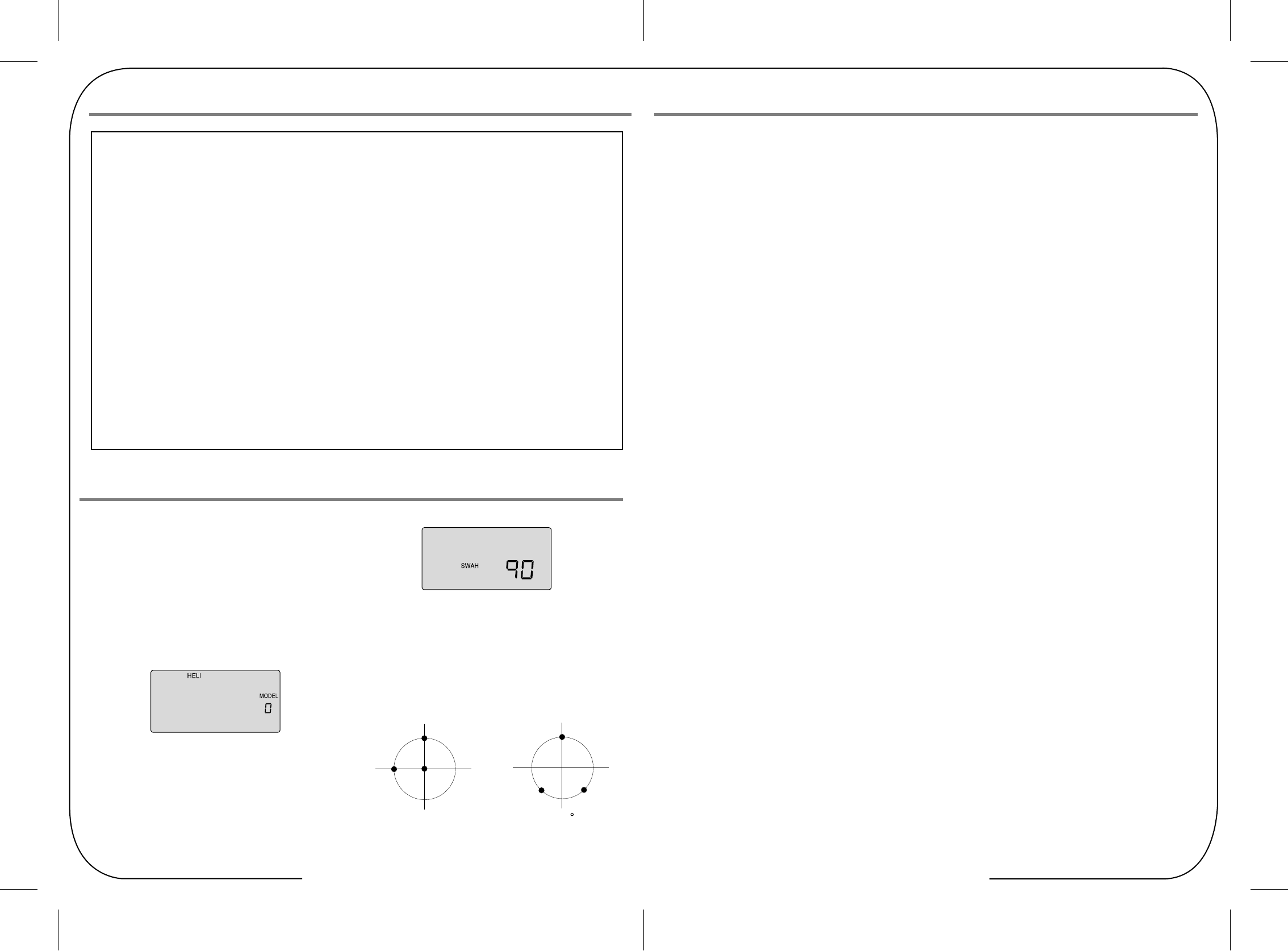
Table of Contents - Page 32 Table of Contents - Page 33
The Tip Sheet If this is your first Heli¡
If this is your first model Helicopter, here are a few tips that will streamline your experience in programming it. This will make
more sense after you read through the manual. Refer back to this section when you are ready to begin the setup:
1. Start with the correct Swash plate setting for your Heli in the Initial Setup Menu.
2. Then use the REV function, and make sure all the servos are moving in the proper direction.
3. After centering the servo arms manually as close as you can, use the S.TRM or sub-trim function to center the servos.
4. Set your servo end points with the EPA function.
5. Read through the section on throttle and pitch curves and have a go at setting the NOR curves. Don't worry about Throttle
Hold, Flight modes and Idle-up curve "stuff" until you can hover and fly well in the NOR mode.
6. Work on the gyro set-up. Read about how your gyro interfaces with different transmitters in the gyro's manual.
7. Program -35% EXPO values for Roll, Ch. 1 and Pitch, Ch. 2.
8. After your heli is all ready to fly, put it on a shelf and go get an R/C flight simulator program for your PC. Spend quality time
crashing the virtual heli in the simulator. Using a sim will save you hundreds of dollars spent on spare parts and countless
hours of rebuilding time in the long run.
9. Ready to fly your new Heli? If you are lucky you will know someone that is an experienced model Helicopter pilot and
would be willing to check over your chopper and take it up for its first flight. This is HIGHLY RECOMMENDED, even if you
have to drive a hundred miles to get to this person! If you are on your own, start slow and use a set of training gear on your
model to prevent tip-overs.
Learn to hover first and then transition into forward flight.
Initial Menu feature review for HELI programming
Model Setup Menu Programming
The following two items are located in the Initial Menu as
described on page XX. We will review them here.
Select the Model type baseline: In the second menu screen,
the programming baseline of ACRO, GLID, or HELI will be
blinking. Since we are setting up a helicopter, select HELI by
scrolling to it with a CURSOR button. Push down both DATA
buttons simultaneously to tell the program to accept the
choice-you should hear the transmitter beep twice in
acknowledgement.
Heli Swash Plate: If you selected HELI as your model type,
this screen will appear allowing you to select between NOR
(Normal 90 degree mechanical) swash plate arrangement or a
120 degree swash plate by pressing one of the CURSOR
buttons. Consult your model's manual to find out which one of
these popular swash formats your heli uses and select it here.
To set up the Optic Sport to fly a particular model, you need to
get into the radio's model setup menu. In this menu you can
program specific control functions and the value (the amount
of servo travel) for the particular model helicopter you selected
earlier in the initial setup menu.
Note: If you have previously set up a model in ACRO, you will
notice that in the HELI programming baseline five new functions
appear that weren't in the ACRO mode. Throttle Curve, Pitch
Curve, Gyro Gain, Revolution Mix and Throttle Hold. All will be
explained in the descriptions of these features which appear
exclusively in the HELI menu.
Now push down both EDIT buttons at the same time.
The following menu items-in the order in which they appear-will
come on the transmitter's LCD screen as you scroll down the
list by pushing down the Right EDIT button:
In the upper left-hand corner it will say "HELI" and to the right
there will be a large number telling you the state of the battery
voltage (such as 7.2 v) and a smaller single-digit number
indicating the model slot the radio is currently opened to.
There will also be a little black box at the bottom of the screen
with the symbol "NOR". This indicates that the system is
currently in the "normal" flight condition mode which in HELI is
also known as the NORMAL curve. Later, we will show you
how to activate the flight condition modes, or "idle-up" stunt
modes-and it is here on the screen where you will be told which
mode is currently active.
Go ahead and switch the transmitter on-you are now in the
standard operating screen
NOR is the standard swashplate where one servo each
performs the collective pitch, elevator, and aileron functions.
120¡Æ is intended for three servo swashplates needing special
mixing to get the servos to properly provide the required pitch,
elevator, and aileron functions. The swashplate type 120¡Æ is
also referred to as SN-3
CH1
CH2
CH6
NOR 120
CH2
CH1
CH6
ROTOR TYPE
Helicopter Controls and Switch Assignments
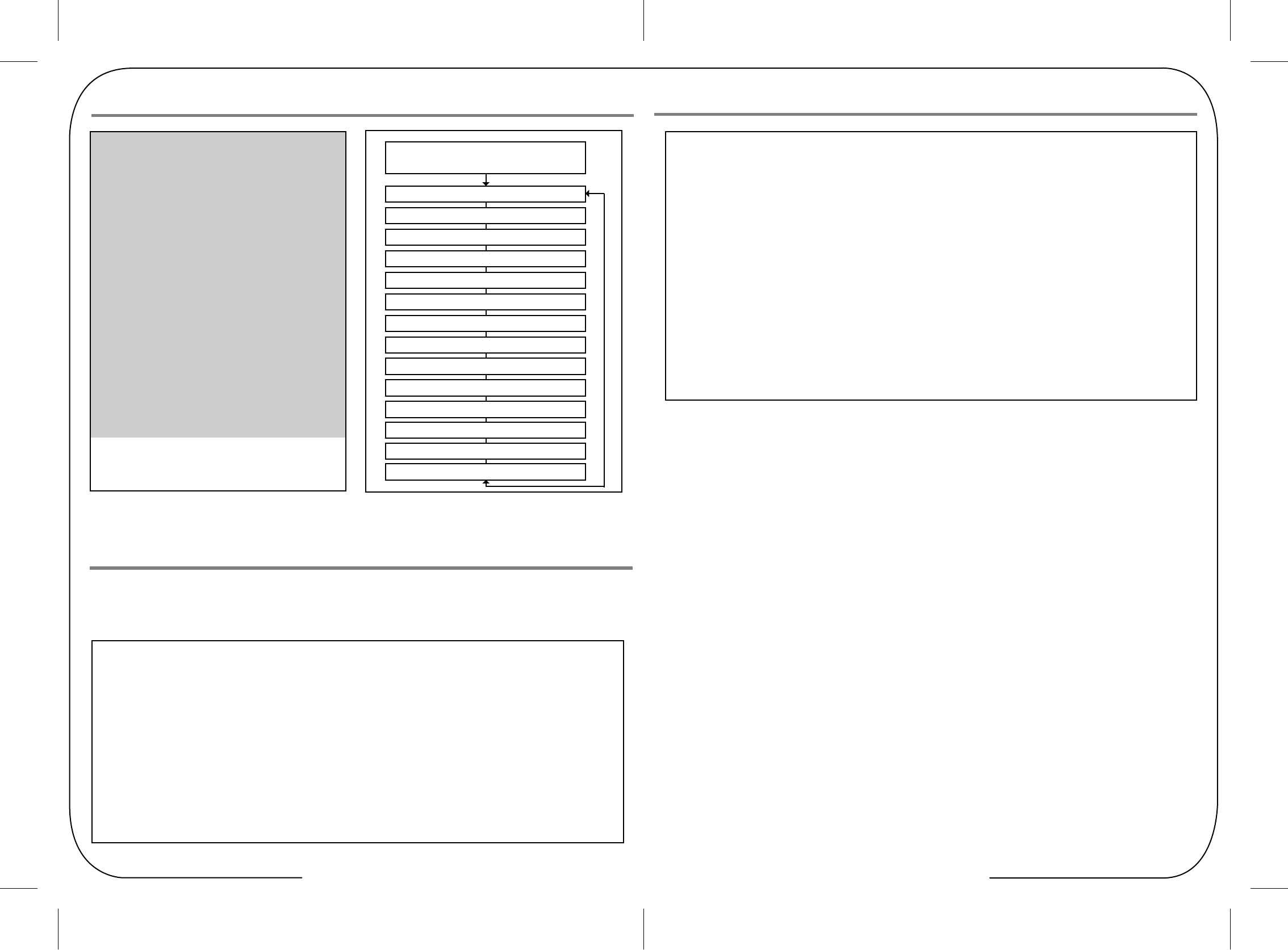
Table of Contents - Page 34 Table of Contents - Page 35
Helicopter Controls and Switch Assignments
Helicopter Controls and Switch Assignments
This section describes how to use the Optic helicopter functions (model type HELI). Descriptions of the other functions, such as
endpoints, dual rates, expo, etc., are contained in the aircraft (ACRO) section
The Tip Sheet
The Two Fundamental Types of Helicopter's: Fixed Pitch and Collective Pitch
There are two fundamental types of model heli's, fixed pitch and collective pitch. The fixed pitch heli is simpler to operate
and has fewer moving parts as the motor or engine RPM controls the speed of the "fixed" pitch blades of the heli.
For this fixed pitch function you will use the Throttle curve function of the Optic Sport, but not the Pitch curve function.
The other, more common, collective pitch setup uses a mix within the electronics of the radio transmitter to combine the
throttle RPM with the adjustable "pitch" or angle of the heli's blades. Both Throttle curves and Pitch curves functions of the
Optic Sport are used to fine-tune the performance of a collective pitch heli.
The Two fundamental types of power: Electric and Glow
There are some subtle, but important differences in the setup methods for glow- versus electric-powered heli's:
If your Heli is powered by a glow engine:
1. A servo plugged into the Ch. 3 slot of the receiver controls the carburetor throttle plate of the engine.
2. Glow heli's also have their own "on-board" battery to power the receiver, gyro and servos.
If your Heli is powered by an electric motor:
1. A proportional ESC (Electronic Speed Control) is plugged into the Ch. 3 receiver slot to control the RPM of the motor.
The Speed Control may have settings that need to be programmed so check the Speed Controller manual.
2. Instead of a fuel tank, a large battery pack provides power to the motor, as well as powering the receiver, gyro and servos
through the BEC (Battery Eliminator Circuit) of the ESC (Electronic Speed Control).
Helicopter Controls and Switch Assignments
Helicopter Functions Map
Helicopter Setup Example 15
EPA End Point Adjust (servo travels) 27
D/R Dual Rates 27
EXP Exponential Settings 28
STRM Subtrim(Netural settings) 28
SREV SERVO Reverse 29
P.MX Programmable Mixer 29
ELVN Elevon mixing(tailless models) 29
FLPN Flaperon(combined flaps & ailerons) 30
VTAL V-tail mixing 30
A->R Rudder Coupling 31
E->F Elevator Flap Mixing 32
CUT Throttle Cut(engine shut off) 33
CAMB Camber(combined flaps & ailerons) 34
FLT.C Flight condition(NOR, ST1, ST2, ST3)
Gear Swich (SW-1) controls receiver CH5
FLT MODE(SW-3)switch Aft = CAMB On
Volage/Timer Display
Normal Display Mode
End Point Adjust [EPA]
Press both Edit Displa
Dual Paste Set [D/R]
Expon ential [EXP]
Sub-Times [S.TRM]
Servo Resbrsing [S.REV]
Prog.Mix [PMX]
Thnottle Curve[R.CV]
Pitch curve[R.CV]
Gyro setting[GYRO]
Revolution[RVMX]
Throttle Hold[HOLD]
Throttle Cut[TCUT]
Swashplate[SWAH]
Flight Conditions FLT.C
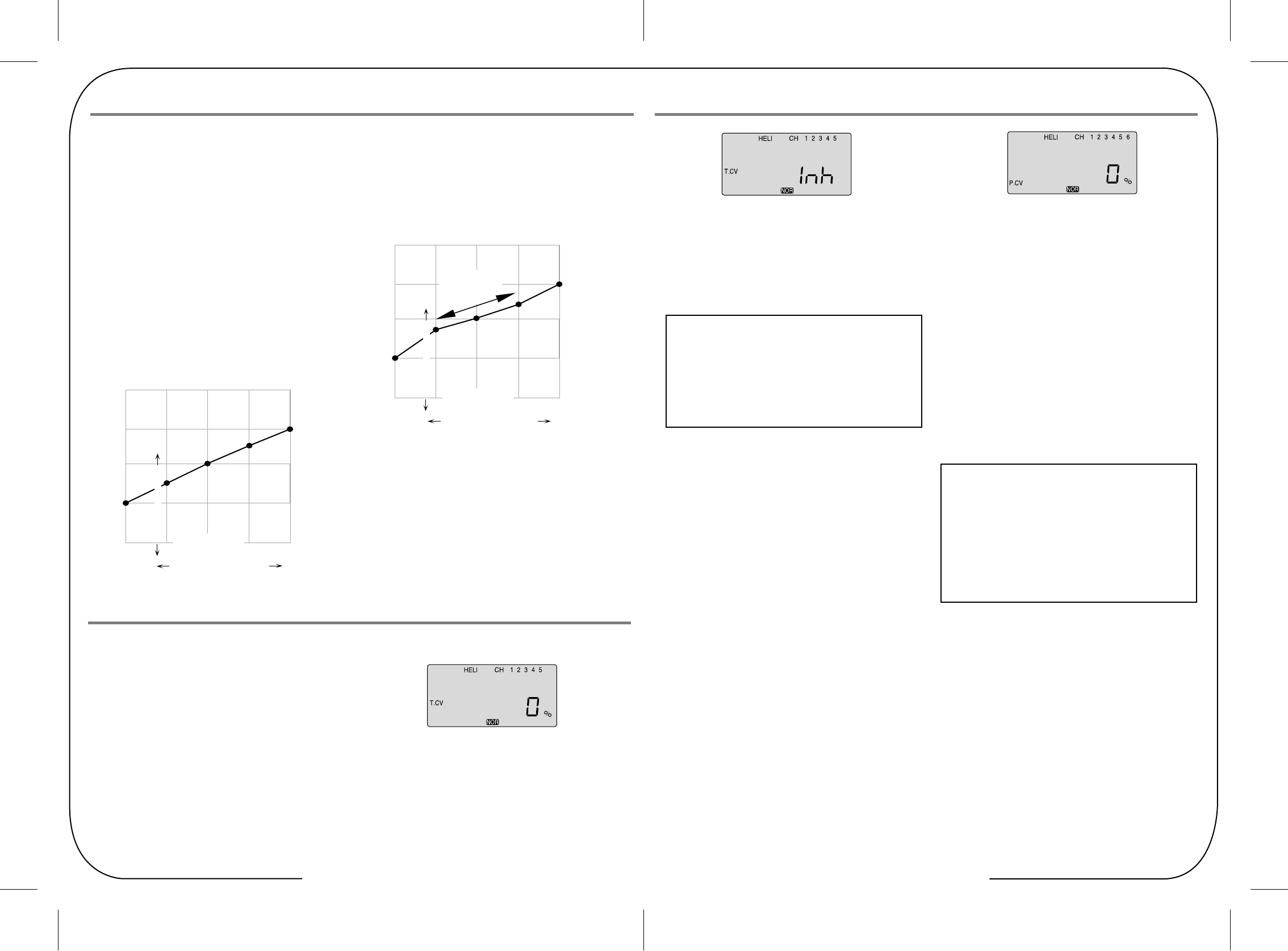
Table of Contents - Page 36 Table of Contents - Page 37
Helicopter Controls and Switch Assignments
P.CV Pitch Curve
GYRO Gyro Gain
Gyro settings are used to automatically control the gyro's gain
in all 4 different flight modes. It may be set to different values
in NOR, ST1, ST2, and ST3 flight modes, allowing you to pick
the gain you need for each circumstance.
The Gyro settings Control the output at receiver CH5. You
cannot independently control this channel with a switch.
There are many manufacturers of gyros. Not all of them setup
the same. Read your gyro manual for a full understanding on
its installation and setup.
Inputting The Pitch Curve Values
Like the throttle curve described previously, pitch curves are
tied to the position of the throttle / collective stick, and are
specified at five points labeled 1 through 5 below.
Setup instructions are the same as those for throttle curve,
except that you may also input a curve for the throttle hold/ST3
flight mode.
If you are a beginner, don't worry about throttle HOLD for awhile.
You can get a linear response by making the five settings line
up as shown above. But if you want another shape, you're free
to do it. You can "flatten out" or "soften" the curve around hover,
which is handy for making the control less sensitive there.
1. Press one of the Up Down EDIT buttons until the P.CV
window appears. The default is for a linear curve, a straight
line from 0 to 100% passing through 50% at hover (center).
2. Be sure you're in the desired flight Modes by moving the Flt.
Mode switch (SW-3) to its proper position. Remember, you
can input separate, independent throttle curve settings for
each separate idle-up mode.
3. You begin at set point #1, idle. A small arrow should appear
over the number 1 in the display, and a value of 0% should
be shown. Press the DATA +Increase or -Decrease button
to change the setting to your desired value.
4. When you're finished with Point 1, move to the next point with
the CURSOR Right button. A small arrow over the number 2
indicates you are setting the value for Point 2. Note that the
function is inhibited (Inh) to start with. If you leave it, you get
a straight line from points 1 to 3. Otherwise, you can change
this setting with the DATA +Increase or -Decrease buttons.
5. Repeat this procedure for Points 3, 4, and 5 by pressing the
CURSOR Right button, then adjusting as desired with the
DATA +Increase or -Decrease buttons.
6. When you've completed the settings for the first flight mode
(NOR), test fly your model. When you're satisfied with the
settings, use them as a basis for the other flight Modes.
Flip the switches as necessary to get into the new mode,
verify on the display that you are in the desired flight mode,
then set all the five points in by going through the steps given
previously
5. Repeat this procedure for Points 3, 4, and 5 by pressing the
CURSOR Right button, then adjusting as desired with the
DATA +Increase or -Decrease buttons.
6. When you've completed the settings for the Throttle curves
in the first flight mode (NOR), go the Pitch Curve section and
setup the pitch curves for the NOR mode.
The Tip Sheet Setting "Idle-Up" curves up in other flight modes
After you learn to fly well in the "NOR" mode, consider
programming the "Idle-Up" curves for doing more advanced
aerobatic or 3D maneuvers. Use the settings in the NOR
curve as a basis for the other flight modes used by
advanced heli pilots.
The Tip Sheet Where are the Hover Throttle and Hover Pitch
controls?
Experienced Heli pilots may be looking for the hover throttle
and hover pitch controls on the Optic Sport. Stop looking as
there aren't any! Fine adjustment of hover throttle and pitch
can be done at the number 3 or middle curve point on both
the throttle and pitch curves menu.
Helicopter Controls and Switch Assignments
Setting Up The Throttle Curve
1. Press one of the Up Down EDIT buttons until the T.CV
window appears. The default is for a linear curve, a straight
line from 0 to 100% passing through 50% at hover
(center, point 3).
2. Be sure you're in the desired flight Mode by moving the Flt.
Mode (SW-1) switch to its proper position. Remember, you
can input separate, independent throttle curve settings for
each separate idle-up mode (except for ST3, throttle hold)!
3. You begin at set point #1, idle. A small arrow should appear
over the number 1 in the display, and a value of 0% should
be shown. Press the DATA +Increase or -Decrease button
to change the setting to your desired value, try about 15 to
20% to start with.
4. When you're finished with Point 1, move to the next point
with the CURSOR Right button. A small arrow over the
number 2 indicates you are setting the value for Point 2.
Note that the function is inhibited (Inh) to start with. If you
leave it, you get a straight line from points 1 to 3. Otherwise,
you can change this setting with the DATA +Increase or
-Decrease buttons.
T.CV Throttle Curve
The throttle & pitch curves are tied to the position of the Throttle
/ Collective stick, and are specified at five points labeled 1through
5 below. These "curves" are really straight lines connecting the
settings at the five points, and are defined by assigning servo
movement percentages to five positions of the left stick:
Lowest stick position = Point 1,
1/4-up stick position = Point 2,
Half-stick = Point 3,
3/4 position = Point 4,
Top stick position = Point 5.
With the numbers defined as shown, the servo would move 50%
of full travel to one side at low collective stick position, and 50%
of full travel to the other side at high stick position.
You can get a linear response by making the five settings line up
as shown above. But if you want
another shape, you're free to do it. You can "flatten out" or
"soften" the curve around hover as shown here.
This is handy for making the control less sensitive around hover.
100%
75%
75%
50%
60%
50%
40%
25%
25%
0%
1 2 3 4 5
Low Collective Stick High
Curve Point
5-Pt Curve Soft Near Hover
Shallower
Slope in this
region
Servo Response
100%
75%
75%
50%
63%
50%
25%
38%
25%
0%
1 2 3 4 5
Low Collective Stick High
Curve Point
Example Five-Point Curve
Servo Response
Table of Contents - Page 38 Table of Contents - Page 39
Helicopter Controls and Switch Assignments
HOLD Throttle Hold
SWAH 120 Swash Plate Programming
5. Set up the RVMX values for the other flight conditions
(ST1, ST2) by flipping the Flt. Mode (SW-3) switch and
repeating these procedures.
The Optic contains settings for 120¡Æ swashplates.
Consult your model's setup instructions to find out whether you
need special swash settings.
The swashplate menu is used to control the response of all
three collective servos as a group. It should NOT be used for
reversing or individual servo travel adjustment. Perform these
settings in the REV and EPA menus respectively. When you
move the collective stick, all swashplate servos should move
in the same direction and the same amount to lift
or drop the swashplate without tilting.
If the swashplate should tilt to one side when you command
collective, one or more servos is moving the wrong direction
or the wrong amount, and must be adjusted in the SWAH menu.
If the swashplate moves down when pitch should be increasing
or vice versa, change the sign in front of all three servos from
(+) to (-) or vice versa. Note that there is no SWAH menu when
the NOR menu is selected, but the 120¡Æ swash type does
contain the SWAH
menu. The swash default settings are shown below.
The Swashplate menu is intended only for helicopters whose
collective pitch is controlled by more than a single servo at a
time, and is sometimes referred to as CCPM
(Collective & Cyclic Pitch Mixing).
The Throttle Hold function moves the engine throttle servo to a
selected position near idle, and disengages it from the throttle
stick. It is commonly used during autorotation, and activated
with the SW-1 switch on the left front of the transmitter.
You can set the throttle position to be held over a -50 to +50%
range centered about the throttle idle position. Activating throttle
hold also disables revolution mixing (RVMX).
1. Press one of the Up Down EDIT buttons until the H0LD
window appears. The default is for the function to be inhibited.
To activate the throttle hold function, press both DATA buttons
at the same time. This will cause the flashing INH display to
change to a 0% value.
2. Now you can adjust the throttle hold position with the DATA
+Increase or -Decrease buttons, anywhere between -25 to
+100% (to return to the default 0%, press the Active/Inhibit
(Clear) button).
3. Check that your throttle goes to the desired hold position by
flipping the SW-1 switch one way and the other.
Adjust the number as needed. Be sure to choose an engine
speed that's fast enough to keep the engine from accidentally
quitting, but slow enough to not engage the main rotor clutch.
Swashplate Programming
1. Consult your model's setup instructions. If three servos are
needed to move the swashplate in a 120¡Æ CCPM set-up,
go to the model setup instructions (at direction) and select
the 120¡Æ swash type.
2. With all the servos hooked up, and the transmitter and
receiver turned on, move the throttle/collective stick up and
down. The swash should move up and down with no
rotations.
Move the aileron stick left and right. The swash should tilt
left and right without pitching or rising. Move the elevator
stick. The swash should tilt fore and aft with no rotations.
If there are rotations when collective is moved, or the swash
moves up and down with aileron or elevator, you need to
adjust the settings in the swash menu.
3. If the servos do not all respond in the same direction for
collective or opposite directions for aileron and elevator, you
will need to reverse one or more of them in the reversing
menu (REV). It may take a little trial and error trying different
combinations of normal and reverse rotation to get the
servos to respond properly. Don't worry about the direction
they respond, just that they all move the same for collective
and tilt for aileron and elevator.
120' NOR
CH1 +70%, CH2 +70%,CH6 +70%
No SWAH menu
RVMX Revolution Mix
The revolution mixing function mixes pitch commands into
rudder (pitch rudder) in order to suppress the torque generated
by changes in the main rotor's pitch angle and rotational speed.
You can input independent values for revolution mixing above
and below one-half throttle for each of the NOR, ST1, and
ST2 flight conditions. Revolution mixing is disabled whenever
throttle hold (ST3, operated by switch SW -1) is on.
For a clockwise-turning rotor, revolution mixing should apply
right rudder when pitch is increased; for a counterclockwise
turning rotor, the opposite should occur. Remember to set the
value for both sides of the throttle stick's motion.
Revolution mixing has no preprogrammed values input at the
start. You will need to input values for your helicopter as
described in the setup example. Note: A procedure for adjusting
revolution mixing is given in a table at direction.
1. Call up the revolution mixing screen by repeatedly pressing
one of the Up Down EDIT buttons until the RVMX window
appears. The function is active with 0% mixing turned on.
Put the throttle stick to its idle position.
2. Now press the DATA +Increase button. This will increase the
percentage of RVMX mixing for the low side of throttle.
You may set a value of 0% to 100% for this side. If you wish
to return the mixing percentage to the default 0% value,
press the Active/Inhibit (Clear) button.
3. Move the throttle stick to a position above half-throttle, and
change the percentage number to suit.
4. Now verify that the rudder responds both the correct
direction and amount for travel on both sides when throttle
is commanded.
The Tip Sheet
Revo mix is used with "Standard Rate Gyros" NOT
"Heading Hold" gyros.
Helicopter Controls and Switch Assignments
3. Flip the Flt. Mode (SW-3) switch to its center position. ST1
will be flashing on and off. Set the percentage to yield the
esired gyro gain in this flight mode (this will usually be a
lower-gain setting for reduced damping in stunts).
4. Flip the Flt. Mode (SW-3) switch all the way forward. ST2
will be Flashing on and off. Set the percentage to yield the
desired gyro gain.
5. Now flip the SW-1 switch fully down. You may now input a
setting for ST3.
6. Make some test flights to try these settings out. Take note
of when more gain is need, and when less gain is needed.
You can adjust all of the gyro settings in each flight mode to
suit your machine.
The Tip Sheet
The following setups for gyro gain values in ST2, ST3 and
ST4 (Throttle Hold), are for advanced users flying in Idle-up
or stunt modes
Using Gyro Settings
1. Press one of the Up Down EDIT buttons repeatedly to get to
the GYRO menu. To begin with, the function is inhibited.
Press one of the CURSOR buttons to activate it. Once
activated, it's set to 50% in all four flight modes.
2. To set the mixing amount for the normal (NOR) flight mode,
flip the Flt. Mode (SW-3) switch all the way back, NOR will
be flashing on and off. Set the percentage to yield the
desired gyro gain (this is usually a high-gain setting).
If for some reason you want a 0% setting, press the Active/
Inhibit (Clear) button.
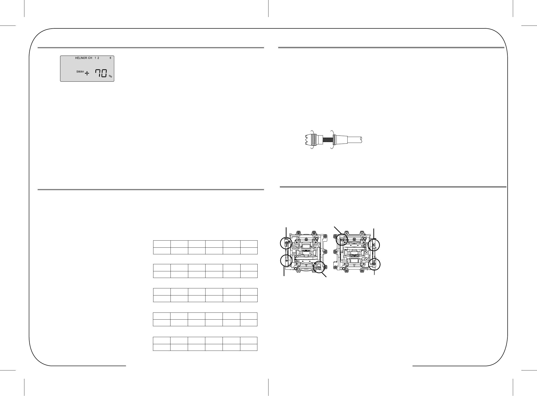
Table of Contents - Page 40 Table of Contents - Page 41
Helicopter Controls and Switch Assignments
Addendum: Other Information
Stick Length Adjustment Stick Lever Tension Adjustment
You may adjust the stick tension of your sticks to provide the
"feel" that you like for flying. To adjust your springs, you'll have
to remove the rear case of the transmitter. Using a screwdriver,
remove the six screws that hold the transmitter's rear cover into
position, and put them in a safe place. Unscrew the antenna and
set it aside. Now, place some padding under the front of the
transmitter and set it face-down on the pad. Gently ease off the
transmitter's rear cover. Now you'll see the view shown.
Using a small cross-point screwdriver, rotate the adjusting screw
for each stick for the desired spring tension.
The tension increases when the adjusting screw is turned
clockwise, and decreases for counterclockwise motion.
When you are satisfied with the spring tensions, you may close
the transmitter. Very carefully reinstall the rear cover.
When the cover is properly in place, tighten the six screws.
An optional training cord is available from your dealer.
The cord may be used to help a beginning pilot learn to fly easily
by allowing a second transmitter, operated by an experienced
instructor, to be connected to this system. The instructor may
override the beginning pilot at any time to bring the model back
under safe control. For training, the transmitter may be connected
to another Hitec FM system using the Hitec cord part # xxxx.
1. Set up both the student's and instructor's transmitters to have
identical trim and control motions. If the instructor's transmitter
is on a different frequency than the student's, use the student's
as the master transmitter and the other as the student's.
2. Collapse the student's antenna, and fully extend the instructor's
antenna. If the student's transmitter has a removable RF
module, remove it from the transmitter.
3. The Hitec cord is specifically marked at one end as the
"master" the other end as "student". Plug it accordingly into
each transmitter, with power switched off. The trainer jack is
on the back of the transmitter. Turn the connector until its
notches lineup and it fits without having to be forced.
4. Turn on the instructor's transmitter. DO NOT turn on the student
transmitter power. Move the controls on the instructor's
transmitter, and verify each control moves the proper direction.
Now verify that the student's trims and control travels match
the instructor's by using the trainer button (the momentary
ENG CUT/TRAINER button on the top right of the transmitter
case) and switching back and forth while leaving the control
sticks and trims alone, then moving the control sticks.
5. The instructor's transmitter has normal control over the model
unless the trainer button is released, passing control to the
student's transmitter. If the student loses control, the instructor
can quickly "take over" by pushing down the trainer button and
controlling the model.
Operating with a Trainer Cord
To use the trainer cord:
You may change the length of the control sticks to make your
transmitter more comfortable to hold and operate.
To lengthen or shorten your transmitter's sticks, first unlock the
stick tip by holding locking piece B and turning stick tip A
counterclockwise. Next, move the locking piece B up or down
(to lengthen or shorten). When the length feels comfortable,
lock the position by turning locking piece B counterclockwise.
A B
TENSION SPRING
TO CLOCKWISE RATCHET COPPER
RATCHET COPPER TENSION SPRING
TO CLOCKWISE
SPRING LIMIT
BRACKET
SPRING LIMIT
BRACKET
Helicopter Controls and Switch Assignments
FLT.C Flight Conditions or "Idle-Up's"
Your Optic system's HELI menu provides three flight modes in
addition to the normal one (NOR). Within each condition, you
may program an independent set of dual rates, exponentials,
throttle and pitch curves, revolution mixing, and gyro gain.
In the HELI menus, these are automatically called up whenever
you switch to a new condition.
NOR is intended for hovering flight. ST1 may be used for
forward flight and mild aerobatics, ST2 may be used for inverted,
and ST3 is used for autorotations as it includes a throttle
hold feature which disengages the throttle servo from collective
commands. These conditions are activated whenever the model
memory is chosen to be HELI type
The defaults for the switches controlling these flight
conditions are as follows:
- NOR: ON when Flt. Mode (SW-3) Switch is BACK.
- ST1: ON when Flt. Mode (SW-3) Switch CENTER.
- ST2: ON when Flt. Mode (SW-4) Switch is FORWARD
- ST3: ON when SW-1 is DOWN. (For Throttle Hold only)
As these functions are switched on or off, ST3 = HOLD has
highest priority, followed by ST2 and ST1. Regular settings (NOR)
occur when all of the others are off.
Throttle and pitch curves, revolution mixing, and gyro gain may
be independently selected for each condition.
Here are some suggested starting settings if your instructions do
not provide any:
Point 1 (low) 2 3 4 5 (high)
% 50 38 50 75 100
Throttle Curve ST2
Throttle Curve ST1
Point 1 (low) 2 3 4 5 (high)
% 100 50 38 50 100
Pitch Curve ST1
Point 1 (low) 2 3 4 5 (high)
Pitch -4 deg. +0.5 +6.0 +7.5 +9.0
Pitch Curve ST2
Pitch Curve ST3 (HOLD)
Point 1 (low) 2 3 4 5 (high)
Pitch -9 deg. -6.0 0 6.0 9 or 10.0
Point 1 (low) 2 3 4 5 (high)
Pitch -4 deg. -- +6.5 -- +12
Helicopter Controls and Switch Assignments
4. Call up the swash screen by repeatedly pressing one of the
Up Down EDIT buttons until the SWAH window appears.
The function is automatically active when you select 120'
mixing in the model setup menu.
5. If all the servos raise the swash with increasing collective,
go to the next step. If they lower the swash, press the
CURSOR Right button twice to get to the collective setting
menu (the arrow appears over the number 6).
Now press the DATA -Decrease button until the sign is
reversed in front of the percentage value. Now the swash
should properly respond to collective. If you've done the
wrong thing, you can reset the percentage by pressing the
Active/Inhibit (Clear) button.
6. If all the servos tilt the swash to the right with right aileron
stick, go to the next step. If they tilt the swash to the left,
press the CURSOR Right button once to get to the aileron
setting menu (the arrow appears over the number 1).
Reverse the sign in front of the percentage with the
DATA -Decrease button.
Now the swash should properly respond to aileron.
7. If all the servos tilt the swash aft with up elevator stick, go to
the next step. If they tilt the swash forwards, press the
CURSOR Right button once to get to the elevator setting
menu (the arrow appears over the number 2).
Now press the DATA -Decrease button until the sign is
reversed in front of the percentage value. Now the swash
should properly respond to elevator.
8. Double check that all three functions, collective, aileron, and
elevator, produce the desired result on the swashplate.
Do not set any SWAH values to 0% or you will disable the
response to that control!
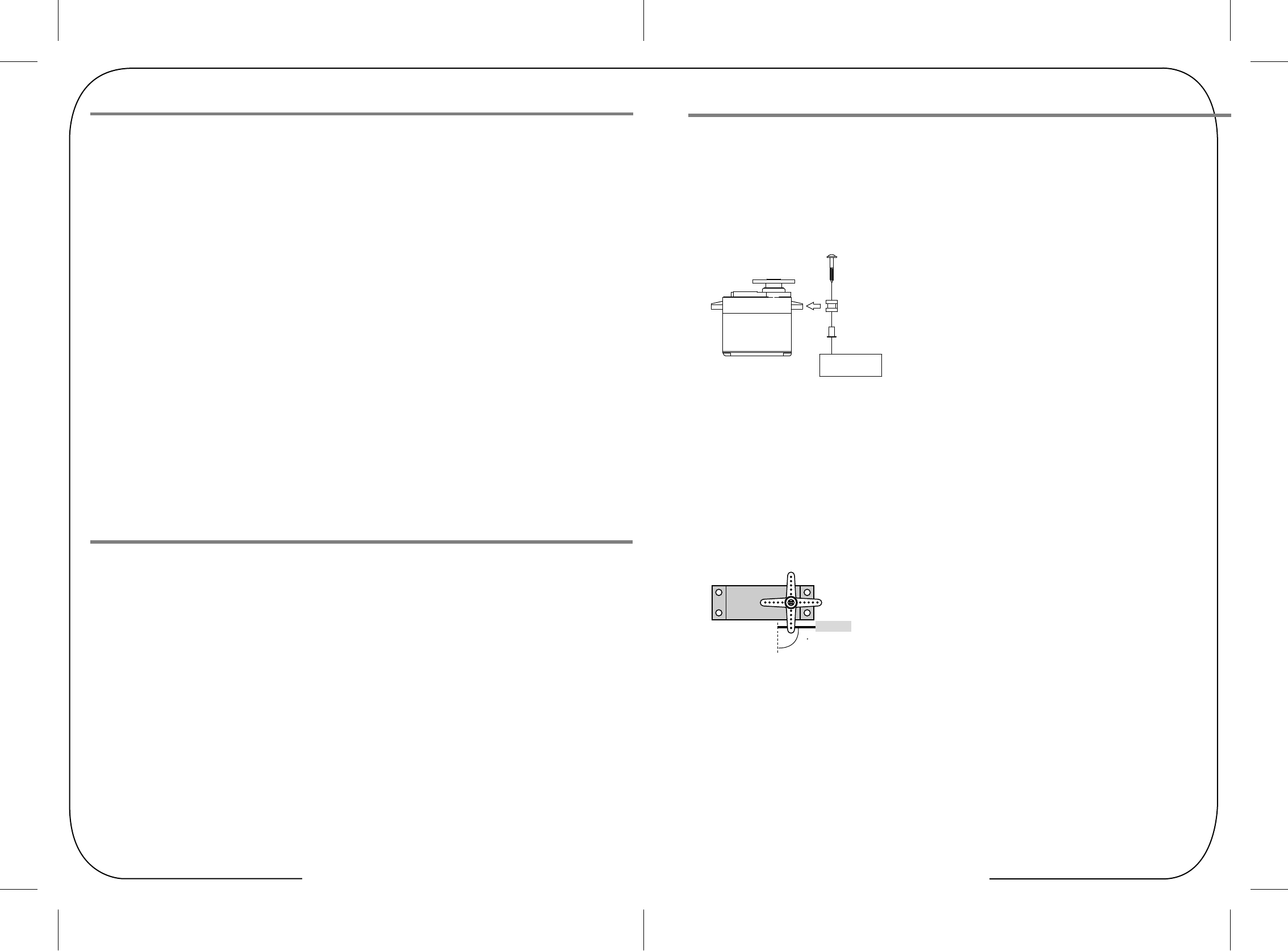
Table of Contents - Page 42 Table of Contents - Page 43
Servo Installation Notes
Mounting
Servo Throw
Factory Repair Service Information
When you mount each servo, use the supplied rubber grommets
and insert an eyelet up through the bottom. Be sure not to over
tighten the screws. If any portion of the servo case directly
contacts the fuselage or the servo rails, the rubber grommets
will not be able to attenuate vibration, which can lead to
mechanical wear and servo failure.
Please read the warranty card supplied with your system and
return it. Before you decide to have your system repaired, if
there is no apparent physical damage, read this instruction
manual again and check to be sure that you are operating the
system as it was designed to be operated. If you are still having
trouble, pack up your system in its original shipping materials
and send it to the nearest authorized Hitec R/C Service Center.
Be sure to include a note in your package that describes the
trouble in as much detail as possible, including:
" Symptoms of the problem in as much detail as you can
provide, including any unusual mounting conditions or
equipment orientation
" A list of items you are sending, and what you want to be
repaired.
" Your name, address, and telephone number.
Glossary
Once you have installed the servos, operate each one over its
full travel and check that the pushrod and output arms do not
bind or collide with each other, even at extreme trim settings.
Check to see that each control linkage does not require undue
force to move (if you hear a servo buzzing when there is no
transmitter control motion, most likely there is too much friction
in the control or pushrod). Even though the servo will tolerate
loads like this, they will drain the battery pack much more
rapidly
Servo
Pushrod
90
Helicopter Controls and Switch Assignments
Using Servo Wire Extensions
You may run the antenna inside of a non-metallic housing
within the fuselage (a plastic outer pushrod housing works well
for this), but range may suffer if the antenna is located near
metal pushrods or cables. Be sure to perform a range check
before flying. With the antenna collapsed, you should be able
to walk 20 - 30 paces from the model without losing control or
seeing "jitter" in the servos. The range check should be done
with the motor running and the model should be securely
restrained in case of loss of control.
Connectors
Be sure the alignment of a servo or battery connector is correct
before inserting it into the receiver. To remove a connector from
the receiver, try to pull on the connector's plastic housing rather
than pulling on the wires. Pulling the wires can ruin the
connector pins and break wires.
If any of your servos are located too far away to plug directly
into the receiver (like the aileron servo), or you need to unplug
the servo each time you disassemble the model, use a servo
extension cord to extend the length of the servo lead.
Additional Hitec extension cords of varying lengths are available
from your hobby dealer.
Radio Installation Notes
Vibration and Waterproofing Switch Harness Installation
Antenna
The receiver contains precision electronic parts. Be sure to
avoid vibration, shock, and temperature extremes.
For protection, wrap the receiver in the provided "Flight
Preserver" foam rubber, or use some other vibration-absorbing
materials. If your flying near bodies of water, it's also a good
idea to waterproof the receiver by placing it in a plastic bag and
securing the open end of the bag with a rubber band before
wrapping it with foam. If you accidentally get moisture inside
the receiver, you may experience intermittent operation or a
crash.
holes and a rectangular hole slightly larger than the full stroke
of the switch. Choose a switch location on the opposite side of
the fuselage from the engine exhaust, and choose a location
where it can't be inadvertently turned on or off during handling
or storage. Install the switch so that it moves without restriction
and "snaps" from ON to OFF and vice versa.
DO NOT cut or coil the receiver antenna wire. It is normal for
the receiver antenna to be longer than the fuselage.
DO NOT cut it or fold it back on itself - cutting or folding
changes the electrical length of the antenna and may reduce
range. Secure the antenna to the top of the vertical fin or the
tail boom, and let the excess length trail behind the aircraft
(be sure it cannot tangle with the tail rotor on a helicopter).
When you are ready to install the receiver's switch harness,
remove the switch cover and use it as a template to cut screw