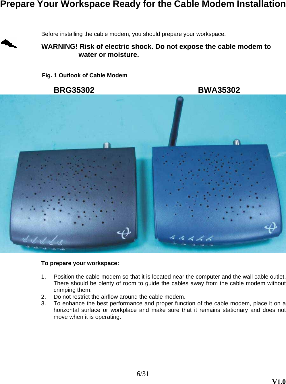
Hitron TECHNOLOGIES 1350001 Wireless Cable Modem User Manual
Hitron TECHNOLOGIES Wireless Cable Modem
UserManual.wiki
>
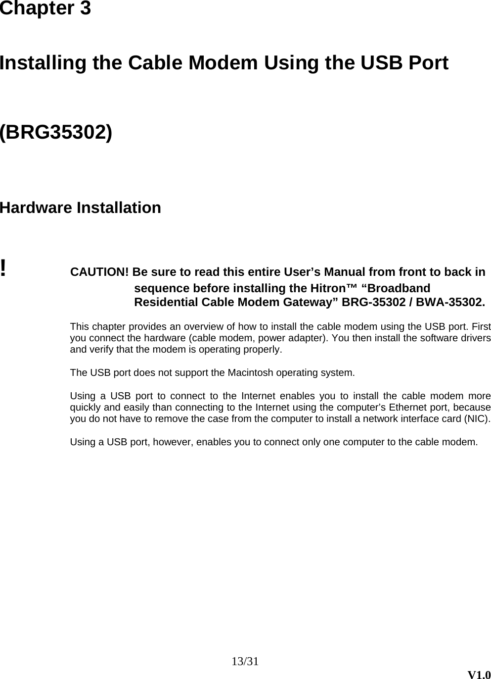
Hitron TECHNOLOGIES
>
1350001 User Manual
Manual
Navigation menu
Upload a User Manual
Namespaces
Wiki Guide
HTML
PDF
Info
Views
User Manual
Discussion / Help
Navigation