Hitron TECHNOLOGIES 1350001 Wireless Cable Modem User Manual
Hitron TECHNOLOGIES Wireless Cable Modem
Manual

1/31 V1.0
DOCSIS 1.1/2.0 Broadband Residential Cable Modem Gateway
BRG-35302/BWA-35302
User Manual
V1.0

2/31 V1.0
Copyright:
Copyright© 2006 HitronTechnologies Inc. All rights reserved.
Revision History:
Revision Date Description Issued by
V1.0 2006/12/6 Initial Draft P. J. Huang
3/31 V1.0
Contents
Before You Begin....................................................................................................................................4
Introduction.....................................................................................................................................4
Cable Modem Features ...........................................................................................................4
Local Cable Network Service.................................................................................................5
Prepare Your Workspace Ready for the Cable Modem Installation ...............................................6
Package Contents............................................................................................................................7
Requirements ..................................................................................................................................7
Verify that you have these items before beginning the installation ........................................7
Decide Which Installation Process to Use..............................................................................7
Installing the Cable Modem Using the Ethernet Port.............................................................................9
Verify the TCP/IP Protocol Configuration....................................................................................10
Configuring TCP/IP on Win 95, Win 98, and Win Me.........................................................10
Configuring TCP/IP on the Windows 2000/XP....................................................................10
Configuring TCP/IP on the Windows NT 4.0.......................................................................10
Configuring TCP/IP on a Macintosh Computer....................................................................11
Connecting the Cable Modem ......................................................................................................11
Installing the Cable Modem Using the USB Port (BRG35302)...........................................................13
Hardware Installation....................................................................................................................13
USB Driver Installation ................................................................................................................15
Windows 98 ..........................................................................................................................15
Windows 2000/XP................................................................................................................15
Windows Me.........................................................................................................................16
Wireless Configuration(BWA35302)..............................................................................................17
Wireless Setting ............................................................................................................................19
Channel and SSID.........................................................................................................................20
SSID......................................................................................................................................20
Channel .................................................................................................................................20
Hide SSID.............................................................................................................................21
Encryption.....................................................................................................................................22
Security .................................................................................................................................22
Authentication Type (WEP Mode only) ...............................................................................24
MAC Filtering...............................................................................................................................25
Cable Modem Front and Rear Panel.....................................................................................................26
Front Panel LEDs..........................................................................................................................27
Rear Panel.....................................................................................................................................29
Notices ..................................................................................................................................................30
Safety Notice & Warning..............................................................................................................30
4/31 V1.0
Chapter 1
Before You Begin
This chapter provides an overview of the Hitron™ “Broadband Residential Cable Modem
Gateway” BRG-35302 / BWA35302 (cable modem) and helps you prepare for its installation.
.! CAUTION! Be sure to read this entire User’s Manual from front to back in
sequence before installing the Hitron “Broadband Residential
Cable Modem Gateway” BRG-35302/BWA-35302 (cable
modem)
Introduction
Thank you for purchasing the Hitron “Broadband Residential Cable Modem Gateway ”
BRG-35302/BWA35302, which is an MCNS DOCSIS™ 2.0 cable modem featuring the latest
DOCSIS technology.
The cable modem enables your network cable operator to provide you with broadband
applications such as telecommunications, IP dedication for your small office/home office
(SOHO), or high-speed residential Internet access. The cable modem provides downstream
speed of up to 38 Mbps from the cable network to your computer and 30 Mbps (128QAM) from
your computer to the cable network.
Another distinctive feature of the cable modem is its easy installation, because DHCP and
TFTP clients can obtain automatic access to the IP address and configuration from their
network servers via the modem. SNMP agents permit remote configuration and monitoring from
a management station equipped with an SNMP server.
Cable Modem Features
This section summarizes the features of the cable modem:
• Full-featured compact, economical cable modem with Ethernet port, USB port (BRG35302)
and Wireless port (BWA35302).
• DOCSIS 2.0 –compliant (EuroDOCSIS 2.0 Compliant), and down compatible to DOCSIS
1.1/1.0
• Equipped TurboDOX that significantly increases the download speed of TCP applications by
factors up to 20 times the downstream throughput. Capable of handling downstream data
transmission speeds up to 38Mbps; upstream to 30Mbps (128QAM).
• RJ-45 10/100BaseT Ethernet port provides traditional industry-standard connection.
• Extensive SNMP management support: MIB-II,
5/31 V1.0
• Ethernetlike MIB, Bridge MIB, Cable Device MIB,
• Baseline privacy Interface MIB, RF Interface MIB
• Front Panel LED display for easy network status monitoring.
• USB connector, with plug n play capability, conveniently located for easy PC access. (BRG35302)
• Support 802.11g, IP address filtering, Hidden SSID, WEP/ WPA-PSK wireless security
(BWA35302).
Local Cable Network Service
Before installing the modem:
1. Read this entire User’s Manual from front to back in sequence.
2. Find the Serial Number, RF and Ethernet address located on the rear panel of the cable
modem and write them here:
Serial Number S/N: ____________________
RF and ETH MAC: ____________________
3. Contact your local cable service operator for Internet/cable network access. Your local
cable operator will check for cable access availability in your area, install a cable line (if
necessary), provide you with an access account, set up configuration and verify other
technical details.
4. Ask your local cable service provider about adding additional IP addresses to your account.
See “Decide Which Installation Process to Use” on page 7 for more information.
6/31 V1.0
Prepare Your Workspace Ready for the Cable Modem Installation
Before installing the cable modem, you should prepare your workspace.
WARNING! Risk of electric shock. Do not expose the cable modem to
water or moisture.
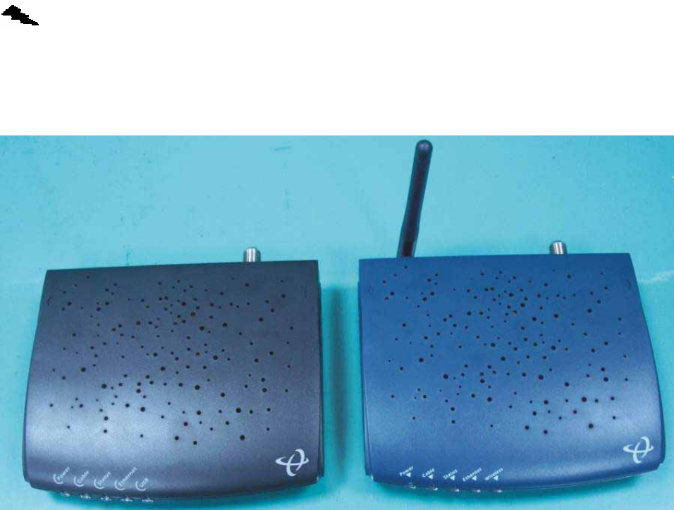
Fig. 1 Outlook of Cable Modem
BRG35302 BWA35302
To prepare your workspace:
1. Position the cable modem so that it is located near the computer and the wall cable outlet.
There should be plenty of room to guide the cables away from the cable modem without
crimping them.
2. Do not restrict the airflow around the cable modem.
3. To enhance the best performance and proper function of the cable modem, place it on a
horizontal surface or workplace and make sure that it remains stationary and does not
move when it is operating.
7/31 V1.0
Package Contents
The package contains:
• Hitron™ “Broadband Residential Cable Modem Gateway” BRG-35302/BWA-35302
• 1 cable modem1 power adapter, (5VDC/1A for BRG-35302; 5VDC/1.5A for BWA-35302).
! Caution: Be sure to use only the power adapter that came with the cable
modem. Using the wrong power adapter can damage the cable
modem or cause unstable while operating.
• 1 180 cm (6') CAT.5 UTP Ethernet cable.
• 1 180 cm (6') CAT 5 UTP USB CABLE (BRG35302)
• 1 Installation Poster
• 1 Installation and Documentation CD containing and.
• Software drivers and user documentation
• User documentation
Requirements
Verify that you have these items before beginning the installation
• A cable-line splitter (not included), if you plan to have the cable modem and a television
connected to the same wall cable outlet.
• An active two-way cable line.
• To install the cable modem using the Ethernet port::
• Any PC running Windows 98, Windows Me, Windows 2000/XP, or Windows NT® or a
computer running any other operating (OS) that supports the TCP/IP Internet
protocol.
• An active Ethernet port on your computer.
• TCP/IP protocol installed. See the “Configuring the TCP/IP Communications
Protocol” section in Chapter 2 for more information on installing the TCP/IP protocol.
Decide Which Installation Process to Use
The cable modem enables you to connect to the Internet using either your computer’s Ethernet
port
Be sure to follow the installation steps for the setup you want to use. Using the Ethernet setup
enables you to use a HUB or switching HUB to connect multiple computers to the cable modem.
To do this, you might have to obtain additional IP addresses from your cable operator.
8/31 V1.0
Using the USB port (BRG35302) enables you to install the cable modem more quickly and
easily than connecting to the Internet using the USB port, because you do not have to install a
network interface card (NIC) into your computer. The USB port, however, only enables you to
connect one computer to the cable modem.
Using the Wireless (BWA35302) enables you connecting to the Internet. For the security
consideration, it is recommended to change the configuration of factory default Wireless
setting..
See “Installing the Cable Modem Using the Ethernet Port” on Chapter2, or see “Installing
the Cable Modem Using USB Port” on Chapter 3 for more information.
9/31 V1.0
Chapter 2
Installing the Cable Modem Using the Ethernet Port
! CAUTION! Be sure to read this entire User’s Manual from front to back in
sequence before installing the Hitron™ “Broadband
Residential Cable Modem Gateway” BRG-35302 / BWA-35302.
This chapter describes how to install the cable modem using the Ethernet port. Using the
Ethernet port enables you to use a single connection to the Internet or use a hub to connect
multiple computers to the cable modem. You can also use multiple IP addresses from your
cable operator when using the Ethernet connection.
You can use the Ethernet port to connect to the Internet with the following operating systems:
Windows® 95, Windows 98, Windows 2000/XP, Windows Me, or Macintosh.
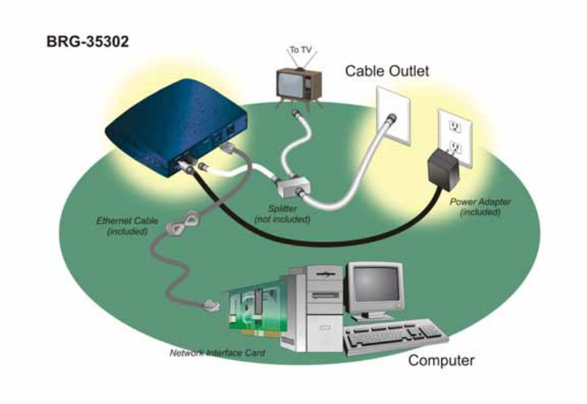
Figure 2 Cable Modem Setup Using the NIC
10/31 V1.0
Verify the TCP/IP Protocol Configuration
Before installing the modem using the Ethernet setup, you must verify that your computer has
the TCP/IP protocol installed. Follow the procedure for your operating system to verify or install
the TCP/IP protocol.
Configuring TCP/IP on Win 95, Win 98, and Win Me
To configure TCP/IP on a computer with the Windows 95, Windows 98, or Windows Me
operating system:
1 Right-click the Network Neighborhood icon (Windows Me: the My Network Places icon)
on the Windows desktop and click Properties.
2 Look for an entry named TCP/IP. If you see TCP/IP listed next to your Ethernet hardware
device, you can now go to the section “Connecting the Cable Modem” on page 11.
However, if TCP/IP is not listed, you must complete the following steps.
a. Click Add.
b. Click Protocol and click Add.
c. Click Microsoft in the Manufacturers list and Click TCP/IP in the Network Protocols
list.
d. Click OK.
e. Click Yes when prompted to restart your computer. You can now go to the section
“Connecting the Cable Modem”
Configuring TCP/IP on the Windows 2000/XP
To configure TCP/IP on a computer with the Windows 2000/XP operating system:
1 Right-click the My Network Places icon on the Windows desktop
2 Right-click Local Area Connection and click Properties. Look for an entry named TCP/IP.
If you see TCP/IP listed next to your Ethernet hardware device, you can now go to the
section “Connecting the Cable Modem” on page 11.
However, if TCP/IP is not listed, you must complete the following steps.
a. Scroll to the Internet Protocol TCP/IP option.
b. Click to place a check mark in the Internet Protocol check box
c. Click OK.
d. You can now connect the cable modem. See the section “Connecting the Cable
Modem” on page 11.
Configuring TCP/IP on the Windows NT 4.0
To configure TCP/IP on a computer with the Windows NT 4.0 operating system:
1 Right-click the Network Neighborhood icon and click Properties.
2 Click the Bindings tab
11/31 V1.0
3 Select All Protocols from the Show bindings from drop-down list.
4 Look for an entry named TCP/IP. If you see TCP/IP listed, double-click it to search for
your Ethernet card. If you see your Ethernet card listed, you can now go to the section
“Connecting the Cable Modem” on page 11. However, if TCP/IP is not listed, you must
complete the following steps:
a. Click the Protocols tab.
b. Click Add.
c. Click TCP/IP Protocol in the Network protocol list.
d. Click OK
e. Click Yes when prompted to restart your computer
f. You can now connect the cable modem. See “Connecting the Cable Modem” on
page 11 for the instructions
Configuring TCP/IP on a Macintosh Computer
Before you install your cable modem, you must verify that the TCP/ IP communications protocol
and an Ethernet device are installed on your system. Many Macintosh computers have Ethernet
devices installed at the factory.
To configure TCP/IP on a Macintosh:
1 Click the Apple icon in the Finder™.
2 Select Control Panels and then TCP/IP. The TCP/IP screen appears.
3 Select Edit in the Finder and select User Mode. The User Mode screen appears.
4 Select Advanced, and then click OK. Additional fields appear on the TCP/IP screen.
5 Click the selector arrows to the right of the Configure: drop-down menu and select Using
DHCP server.
6 Click Options. The TCP/IP Options screen appears.
7 Select Active and check the Always Connected check box.
8 Click OK. The TCP/IP dialog box appears.
9 Verify that the Use 802.3 check box is unchecked. If the box is checked, click the box to
remove the check mark. Then click Info.
10 Click OK. If you have made any changes, you are prompted to save the settings.
11 Click OK to save the settings and exit
12 Click OK and close the TCP/IP Control Panel (click File and scroll down to click Close).
Connecting the Cable Modem
Install the cable modem according to the following procedure:
1 Power off the computer.
2 Unplug the computer from the electrical wall outlet.
3 Make these connections:
a. Connect the coaxial cable to the cable modem’s CATV cable connector. If you plan
to have the cable connected to a television as well as the cable modem, you must
use a cable line splitter (not included).
b. Plug the cable modem’s power adapter into a wall outlet or surge protector and into
the cable modem’s power jack.
c. Plug one end of the Ethernet cable into the cable modem’s Ethernet port and the
other end of the cable into the existing NIC.
4 Plug in the computer.
5 Power on the computer. When installation is complete, your setup should resemble the
12/31 V1.0
illustration above. The modem is operating properly if the Power, RF/DS, RF/US, and
Status light emitting diodes (LEDs) are solid green (lit and not blinking).
13/31 V1.0
Chapter 3
Installing the Cable Modem Using the USB Port
(BRG35302)
Hardware Installation
! CAUTION! Be sure to read this entire User’s Manual from front to back in
sequence before installing the Hitron™ “Broadband
Residential Cable Modem Gateway” BRG-35302 / BWA-35302.
This chapter provides an overview of how to install the cable modem using the USB port. First
you connect the hardware (cable modem, power adapter). You then install the software drivers
and verify that the modem is operating properly.
The USB port does not support the Macintosh operating system.
Using a USB port to connect to the Internet enables you to install the cable modem more
quickly and easily than connecting to the Internet using the computer’s Ethernet port, because
you do not have to remove the case from the computer to install a network interface card (NIC).
Using a USB port, however, enables you to connect only one computer to the cable modem.
14/31 V1.0
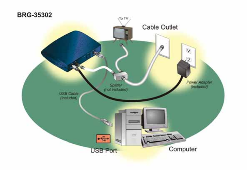
Fig 3 Cable Modem Setup using USB port
Install the cable modem according to the following procedure:
1 Power off the computer (and television, if you plan to have the cable modem and
television connected to the same wall cable outlet).
2 Unplug the power cord of computer (and television).
3 Connect the coaxial cable to the cable modem’s cable television (CATV) cable
connector.
4 Connect all of the devices:
a. If you plan to have the cable modem and a television connected to the same wall
outlet, you must use a cable line splitter (not included).
b. Plug the cable modem’s power adapter into the cable modem’s power jack and into
a grounded electrical outlet or surge protector that is plugged into a grounded
electrical outlet.
CAUTION! You must use the 5VDC power adapter that comes with
the Hitron BRG-35302 cable modem. Using the wrong
power adapter can damage the cable modem.
c. Connect the USB end of the cable modem to the USB port on your computer using a
USB cable.
5 Plug the power cord of computer (and television.)
6 Power on the computer (and television.)
7 Now your connection should be similar to the Fig. 3.
15/31 V1.0
8 The modem is operating properly if the Power, RF/DS, RF/US, Status and USB light
emitting diodes (LEDs) are solid green (lit and not blinking).
9 You must now install the software drivers provided on the Installation CD. Be sure to
follow the instructions (below) for your specific operating system.
USB Driver Installation
After the Hardware Installation, you must install the USB software driver.
Windows 98
After the Hardware Installation, the window “Found New Hardware” appears. Please follow the
instruction in “Add New Hardware Wizard”
1. Select Search for the best driver for your device (Recommended) and click Next.
2. Check the Specify a Location check box. The location of the driver file is :
D:\Drivers\Generic_Compact_CM_USB
where D is the letter of your computer's CD-ROM drive.
If necessary, replace D with the letter of your computer's CD-ROM drive. You can either click Browse
to locate the driver file, or type D\Drivers\Generic_Compact_CM_USB into the field next to the
Browse drop-down list.
3. Click Next to search for the necessary driver files.
4. Select The updated driver (Recommended) and click Next. When the system locates the driver files,
click Next to automatically install the necessary files.
5. When prompted, insert the Windows 98 SE CD into the CD-ROM drive and click OK.
6. After Windows copies the necessary system files, click Finish. The system Settings Change dialog
box appears.
7. Click Yes to reboot your computer.
8. Make sure the LED of Power, Cable, Status and USB are green without blinking, which means the
installation is finished. Please refer to Chapter 5: “Cable Modem Front and Rear Panel” for
more information.
Windows 2000/XP
The Found New hardware Wizard screen appears.
1. Select Search for a suitable driver for my device (Recommended) and click Next.
2. Check the CD-ROM drives check box and click Next to search for the necessary driver files. The
location of the driver files is:
D:\Drivers\Generic_Compact_CM_USB
where D is the letter of your computer's CD-ROM drive.
3. When the Found New Hardware Wizard displays the search results, click Next to install the
necessary driver files.
Note: If the Digital Signature Not Found screen appears, click Yes to continue the installation.
4. When the Found New Hardware Wizard completes the installation, click Finish.
5. Make sure the LED of Power, Cable, Status and USB are green without blinking, which means the
installation is finished. Please refer to Chapter 5: “Cable Modem Front and Rear Panel” for
more information.
16/31 V1.0
Windows Me
When the CM is powered on, the Add New hardware Wizard screen appears.
1. Select Automatically search for a better driver (Recommended) and click Next.
2. When Windows locates the driver files click Next to install the necessary files.
3. Click Finish. The system Settings Change dialog box appears.
4. Click Yes to reboot your computer.
5. Make sure the LED of Power, Cable, Status and USB are green without blinking, which means the
installation is finished. Please refer to Chapter 5: “Cable Modem Front and Rear Panel” for
more information.
17/31 V1.0
Chapter 4
Wireless Configuration(BWA35302)
! CAUTION! Be sure to read this entire User’s Manual from front to back in
sequence before installing the Hitron™ “Broadband
Residential Cable Modem Gateway” BRG-35302 / BWA35302.
This chapter provides an overview of how to set up the Wireless parameters via Ethernet Port
Interface. First you can refer to chapter 2: “Installing the Cable Modem Using the Ethernet
Port” and verify that the Ethernet Port is operating properly.
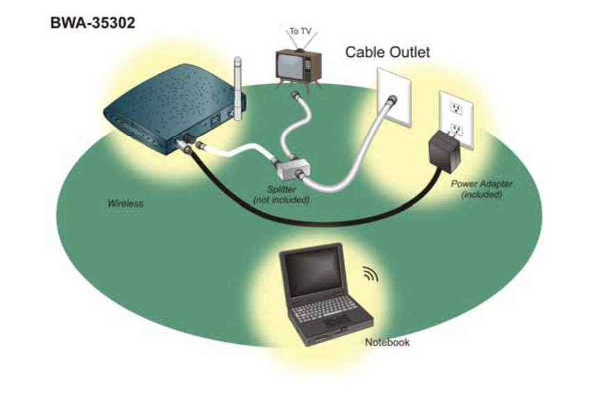
After making sure the Ethernet Port works fine, please connect the Cable Modem and your
computer via the Ethernet Cable (Included in the accessories.).
Fig. 4 Cable Modem Connection Using Wireless
The Factory Default IP address of the Ethernet Port is 192.168.100.1, and the DHCP server is
enabled. You can configure your computer as “Automatic Get the IP”, or set the IP as

18/31 V1.0
192.168.100.2, mask = 255.255.255.0, so that the computer and the Cable Modem will be
connected.
Open the Browser in your computer and key in http://192.168.100.1, you will be asked to key in
the username and password..
As for the Username and Password, you can contact your service provider for the details.
19/31 V1.0
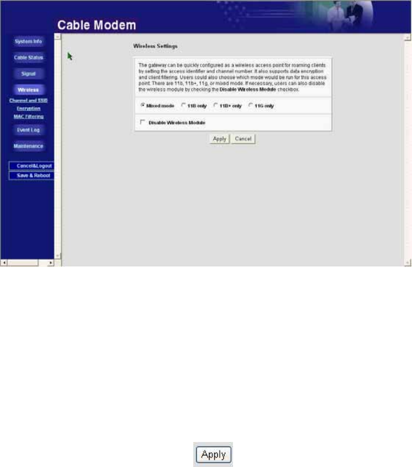
Wireless Setting
There are several wireless transmission modes for selection:
802.11b(11B):It is of the old transmission mode. The max speed can be up to 11Mbps.
802.11b+(11B+):The formal description should be Packet Binary Convolutional Coding
(PBCC). It is of the enhanced transmission mode of 11B, and the max
speed can be up to twice of 11B (22Mbps).
802.11g(11G):It is the fastest among the three transmission modes, and the max speed
can be up to 54Mbps. However, some older wireless LAN card may not
support.
If you are not sure whether your wireless LAN card supports or not, it is recommended to select
as Mixed Mode.
The Factory Default is “Mixed mode”.
User can also disable the wireless transmission module. It is just to click the left side of
the ”Disable Wireless Module”.
After the configuration, please click below.
20/31 V1.0
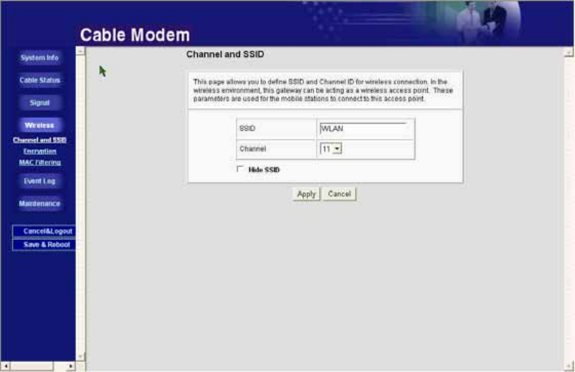
Channel and SSID
SSID
SSID(Service Set Identification)is the “name” of this wireless access point. It is also called the
“Wireless Network Name” in the Windows XP environment.
While the wireless LAN card searches for the access point, SSID is the important information for
user to judge which Wireless Access Point is the expected one.
SSID can be configured up to 32characters.(Alphabet or number).
The Factory Default of SSID is WLAN.
Channel
This selection is correlated to the transmission frequency. Different Channel means the different
transmission frequency.
In most of the application, it is not necessary to change the channel. It is due to that the wireless
LAN cards can detect the correct channel while they are searching the access point.
One of the reasons for you to change the channel is that there is the frequency interference
happened. The possibility of the interference may result from that there are more than one
access points using the same channel in the small area. If so, you can select different channels
to avoid the interference.
21/31 V1.0
Hide SSID
For security, wireless access point can disable the broadcast of SSID, and the configuration is
to select the “Hide SSID”.
Once the “Hide SSID” is selected, only the computer with same SSID can connect the wireless
access point.
On the other hand, the computer with the different SSID (or without SSID) will not “see” this
wireless access point.
To connect the wireless access point with the configuration “Hide SSID”, user must know the
SSID in advance, and then pre-configure in the computer. After the configuration, the hidden
SSID will appear in the search list.
22/31 V1.0
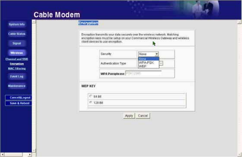
Encryption
The wireless LAN signal is broadcasted openly. This is vulnerable for information theft or
hackers trying to sniff your private information. To provide a certain level of protection, it is
recommended to enable the authentication for the connection and the encryption of the
transmission data.
Security
In the selection in Security, user can select between None, WPA-PSK and WEP.
None:
There will be no authentication or encryption in this mode.
WPA-PSK:
WPA-PSK(Wi-Fi Protected Access Pre-Shared Key)provides strong data security. It will block
eavesdropping. Because this is a new standard, wireless device driver and software availability
may be limited.
The Passphrase must be identical on all PCs and access points in your network. Enter a word or
group of printable characters in the Passphrase box. The length of Passphrase should be between
23/31 V1.0
8~63 characters, which can be alphabet, number, symbol, even the blank.
WEP:
The WEP is similar to the WPA-PSK. There is the encryption key between the PCs and access
point, too.
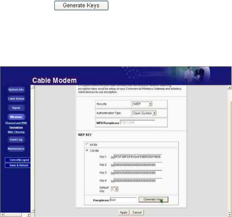
There are two encryption lengths for selection: 64 bits and 128 bits.
If encryption strength is set to 64-bit or 128-bit, then only the selected WEP key box will
automatically be populated with key values.
For 64-bit WEP, enter 10 hexadecimal digits (any combination of 0-9, a-f, or A-F).
For 128-bit WEP, enter 26 hexadecimal digits (any combination of 0-9, a-f, or A-F).
No matter 64 bits or 128 bits, you can program four data encryption keys.
You can manually or automatically program the four data encryption keys. These values must be
identical on all PCs and Access Points in your network.
‧ Automatic — enter a word or group of printable characters in the Passphrase box and click
the . The key boxes will be automatically populated with key
values.
(Note: In 64 bits, there will generate four data encryption keys. In 128 bits, it will
generate only one data encryption key. )
‧ Manual — enter 10 hexadecimal digits (any combination of 0-9, a-f, or A-F )Select which of
the four keys will be active.
24/31 V1.0
Authentication Type (WEP Mode only)
Once the security mode is selected as WEP, one may need to select the Authentication Type.
There are two selections in Authentication Type: Open System and Shared Key.
The difference between Open System and Shared Key is the Authentication between Access
Point and Computer.
.
Open System
In the Open System environment, there will not the authentication between Access Point
and Computer.
The Access Point will allow the connection for any computer which sends the connection
request. Once connected, the Access Point will ask the Computer to send the WEP Key so
that they can arrange the encryption of the transmission data.
Shared Key
In the Shared Key environment, it must go through the Authentication procedure before the
connection between Access Point and Computer.
In order to finish the Authentication, the Computer must be pre-configured as Shared Key.
Meanwhile, the WEP Key must be keyed in the Computer in advance. Otherwise, the
Access Point will reject the connection request.
(Note 1: The Authentication Type must be the same between Access Point and Computer.
If one side is of Open System and the other is Shared Key, they will not be able
to connect.)
(Note 2: This is only of the Authentication between Access Point and Computer. Once
they are connected, the transmission data are always encrypted by WEP.)
(Note 3: The default configuration is “Automatic”, which can auto switch between these
two modes.)
25/31 V1.0
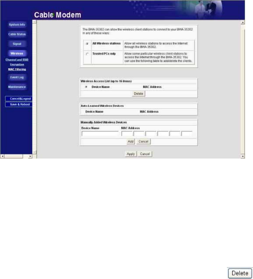
MAC Filtering
To restrict access based on MAC addresses, you can set up a list of the Trusted Devices, which
are allowed to connect to the Access Point.
If the “All Wireless Stations” is selected, the Access Point can accept all of the connection
requests.
If the “Trust PCs only” is selected, the Access Point only accepts the Computer in the
pre-configured list.
The list is according to the MAC address. Only the Computer in the List can be accepted, the
others will be rejected.
To add one trusted PC: Key in the MAC address in the “Manually-Added Wireless Devices”.
You can also set the Device Name for verification.
The added PC will be shown in the “Wireless Access List”.
To remove one trusted PC: Select the MAC address in the “Manually-Added Wireless
Devices” which you want to remove, and then click .
You can see the connected Computer in the “Auto-Learned Wireless Devices”.
26/31 V1.0
Chapter 5
Cable Modem Front and Rear Panel
! CAUTION! Be sure to read this entire User’s Manual from front to back in
sequence before installing the Hitron “Broadband Residential
Cable Modem Gateway” BRG-35302/BWA-35302 (cable
modem).
This chapter describes the light emitting diodes (LEDs) on the front panel and the connectors
on the rear panel of the cable modem.
27/31 V1.0
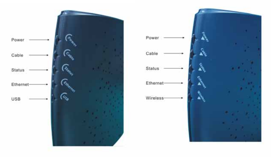
Front Panel LEDs
The LEDs on the cable modem indicate:
• The current performance of the cable modem.
• The condition of the network connection between the cable modem and your cable service
provider.
• The condition of the connection between your cable modem and electrical power.
Fig. 5 Front Panel LEDs
BRG35302 BWA35302

28/31 V1.0
Fig. 6 LED Status
LED Label Color Description
Power Green Cable modem is plugged in to an electrical outlet and is
receiving power
Cable Orange-Blinking
Orange
Green
The modem is searching for the DOWNSTREAM frequency
Downstream frequency is locked. Searching for UPSTREAM
frequency.
Upstream frequency is locked
Status Green-Blinking
Green Modem is registering with the cable company's head-end
Modem is ready for data transfers
ETH Green
Green-Blinking Valid Ethernet link status
Cable modem is transmitting/receiving data through the
Ethernet port
USB
(BRG35302) Green
Green-Blinking USB interface is connected
Data is being sent/received through the USB port
Wireless
(BWA35302) Green
Green-Blinking Wireless interface is connected
Data is being sent/received through the Wireless port
29/31 V1.0
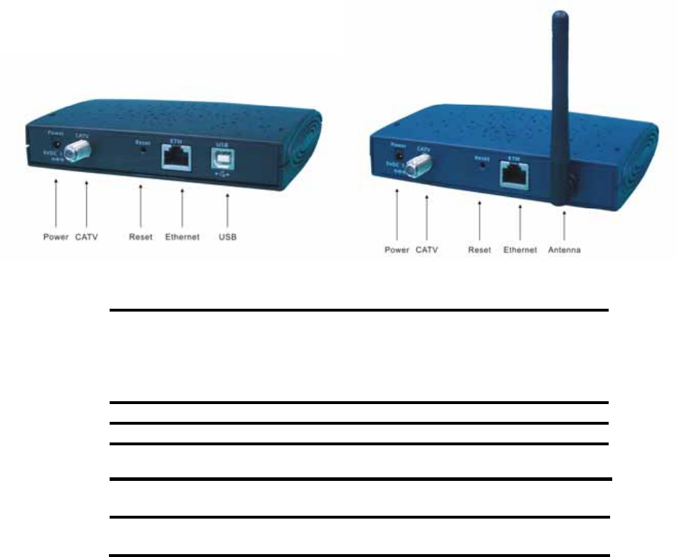
Rear Panel
Fig. 7 Rear Panel
BRG35302 BWA35302
Fig. 8 Rear Panel Interface
PWR 5V/1A (BRG-35302)
5V/1.5A (BWA-35302)
Caution: Be sure to use only the power adapter that came with
the cable modem. Using the wrong power adapter can
damage the cable modem or cause unstable while
operating.
CATV RF connector to attach the cable for broadband Internet access.
ETH RJ-45 female socket for connection of Ethernet cable
RESET For restart (Press once), or Restores factory default settings(Press
steadily for 10 seconds)
USB
(BRG35302)
USB 'B'-type socket. Connects through USB cable to computer's
USB 'A'-type port.
Antenna
(BWA35302) Wireless Antenna

30/31 V1.0
Chapter 6
Notices
! CAUTION! Be sure to read this entire User’s Manual from front to back in
sequence before installing the Hitron “Broadband Residential
Cable Modem Gateway” BRG-35302/BWA-35302 (cable
modem)
Safety Notice & Warning
WARNING! Risk of electric shock. Do not expose the cable modem to
water or moisture..
! Caution: Be sure to use only the power adapter that came with the cable
modem. Using the wrong power adapter can damage the cable
modem or cause unstable while operating.
1 The Broadband Residential Cable Modem is a high-performance communications device
designed for home and office environments. Do NOT use the cable modem outdoors.
Keep the cable modem in an environment that is between O C and 40 C (between 32 F
and 104 F). See Product Specifications for more information.
2 To avoid overheating the cable modem, do NOT place any object on the top of the cable
modem. Do not restrict the flow of air around the cable modem.
3 The manufacturer assumes no liabilities for damage caused by any improper use of the
cable modem.
4 Plug the cable modem’s power adapter into the cable modem’s power jack and into a
grounded electrical outlet or surge protector that is plugged into a grounded electrical
outlet.

31/31 V1.0
Product Specification:
Dimensions 120 mm (L) x 142mm (W) x 30mm (H))
Power 5V/1A (BRG35302)or 5V/1.5A(BWA35302)
Power Consumption Max 4 Watts(BRG35302)/ Max 7 Watts (BWA35302)
Operating Temperature 0°C ~ 40°C (32°F ~ 104°F)
Operating Humidity 10%~90% Non Condensing
Cable Interface Female “F” Type RF Connector
CPE Interface RJ-45 10/100BaseT, USB B-Type(BRG35302)
Downstream transmission
speed (MAX) 38Mbps
Upstream transmission
speed (MAX) 10Mbps(DOCSIS 1.0/DOCSIS 1.1)
30Mbps(DOCSIS 2.0)
Federal Communication Commission Interference Statement
This equipment has been tested and found to comply with the limits for a
Class B digital device, pursuant to Part 15 of the FCC Rules. These limits
are designed to provide reasonable protection against harmful interference in
a residential installation. This equipment generates, uses and can radiate
radio frequency energy and, if not installed and used in accordance with the
instructions, may cause harmful interference to radio communications.
However, there is no guarantee that interference will not occur in a particular
installation. If this equipment does cause harmful interference to radio or
television reception, which can be determined by turning the equipment off
and on, the user is encouraged to try to correct the interference by one of the
following measures:
- Reorient or relocate the receiving antenna.
- Increase the separation between the equipment and receiver.
- Connect the equipment into an outlet on a circuit different from that
to which the receiver is connected.
- Consult the dealer or an experienced radio/TV technician for help.
This device complies with Part 15 of the FCC Rules. Operation is subject to
the following two conditions: (1) This device may not cause harmful
interference, and (2) this device must accept any interference received,
including interference that may cause undesired operation.
FCC Caution: Any changes or modifications not expressly approved by the
party responsible for compliance could void the user's authority to operate this
equipment.
IMPORTANT NOTE:
FCC Radiation Exposure Statement:
This equipment complies with FCC radiation exposure limits set forth for an
uncontrolled environment. This equipment should be installed and operated
with minimum distance 20cm between the radiator & your body.
This transmitter must not be co-located or operating in conjunction with any
other antenna or transmitter.
IEEE 802.11b or 802.11g operation of this product in the U.S.A. is
firmware-limited to channels 1 through 11.