Hitron TECHNOLOGIES CGN01A 3x3 802.11n WiFi Router User Manual
Hitron TECHNOLOGIES 3x3 802.11n WiFi Router
UserManual.wiki
>
Hitron TECHNOLOGIES
>
CGN01A User Manual
User manual
Navigation menu
Upload a User Manual
Namespaces
Wiki Guide
HTML
PDF
Info
Views
User Manual
Discussion / Help
Navigation
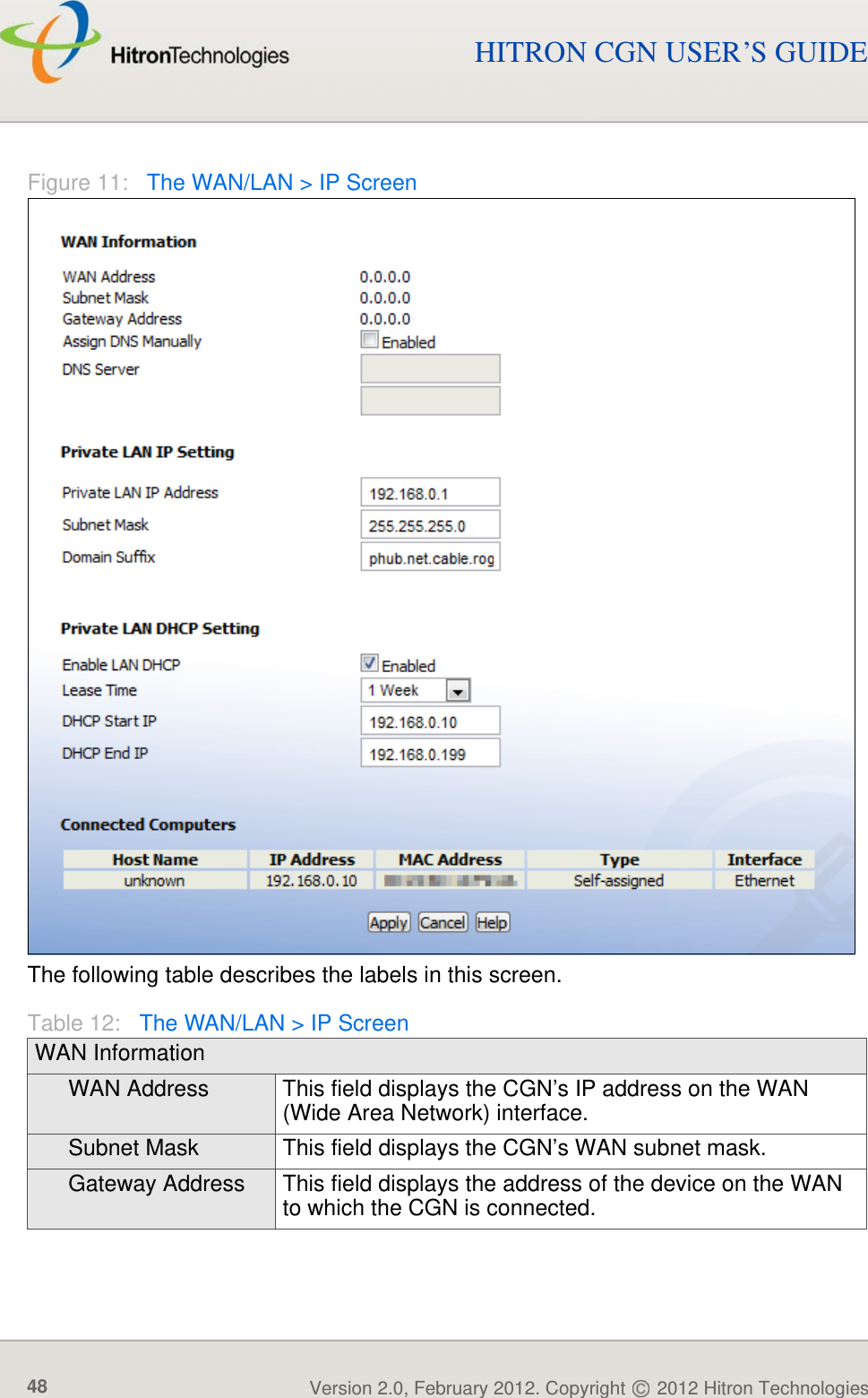
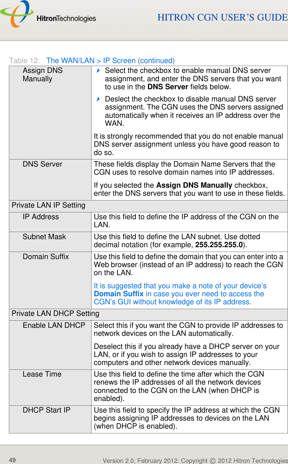
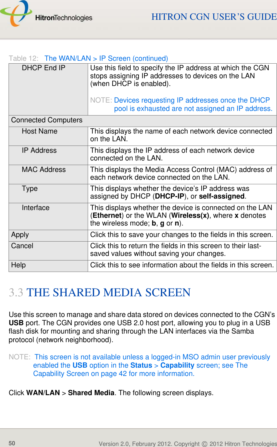
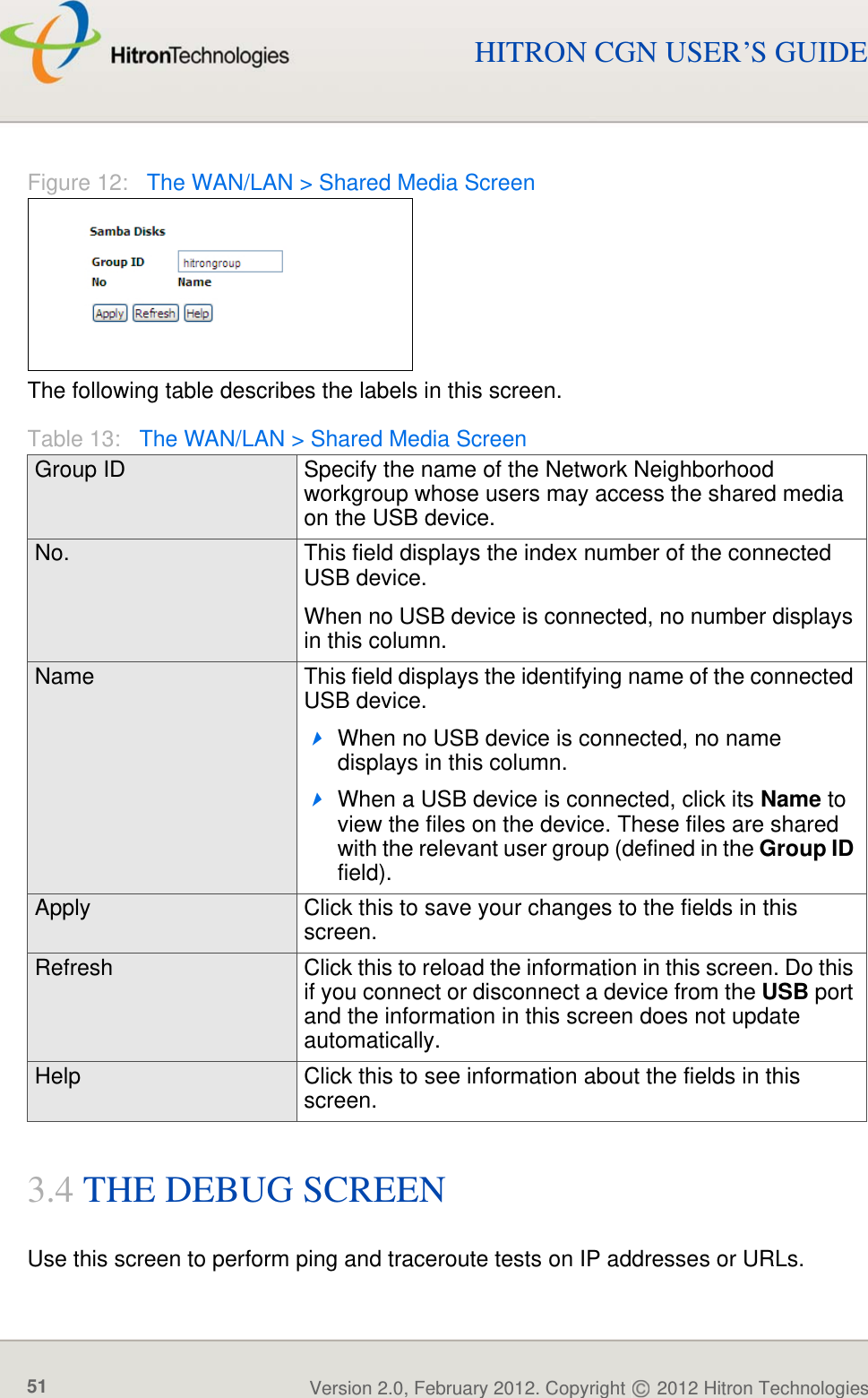
![ABOUT THIS USER’S GUIDEVersion 2.0, February 2012. Copyright 2012 Hitron Technologies3Version 2.0, February 2012. Copyright 2012 Hitron Technologies3HITRON CGN USER’S GUIDEDOCUMENT CONVENTIONSThis User’s Guide uses various typographic conventions and styles to indicate content type:Bulleted paragraphs are used to list items, and to indicate options. 1 Numbered paragraphs indicate procedural steps.NOTE: Notes provide additional information on a subject.Warnings provide information about actions that could harm you or your device.Product labels, field labels, field choices, etc. are in bold type. For example:A mouse click in the Graphical User Interface (GUI) is denoted by a right angle bracket ( > ). For example:means that you should click Settings in the GUI, then Advanced settings.A key stroke is denoted by square brackets and uppercase text. For example:CUSTOMER SUPPORTFor technical assistance or other customer support issues, please consult your Hitron representative.Select UDP to use the User Datagram Protocol.Click Settings > Advanced Settings.Press [ENTER] to continue.](https://usermanual.wiki/Hitron-TECHNOLOGIES/CGN01A/User-Guide-1663467-Page-3.png)
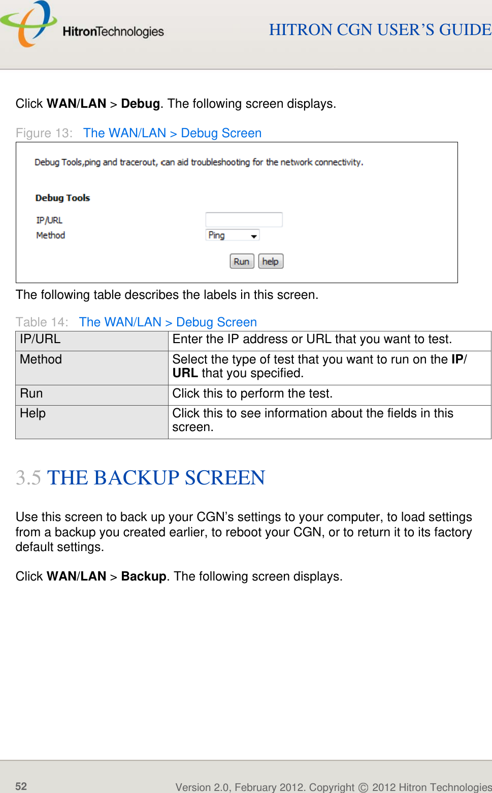
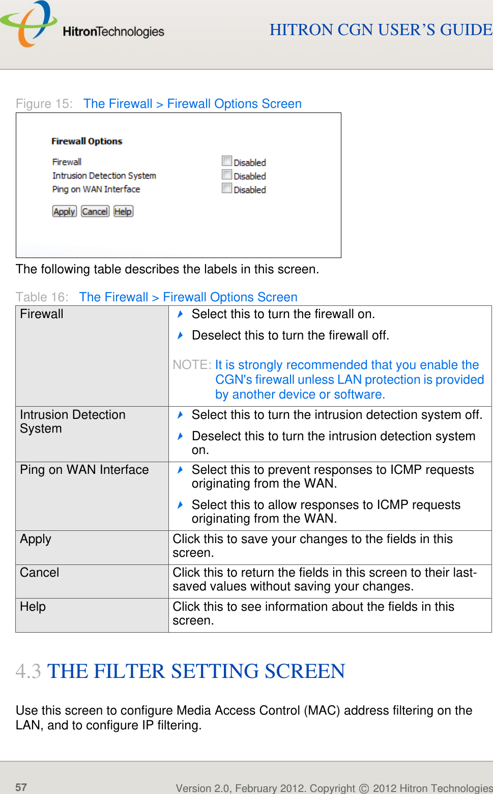
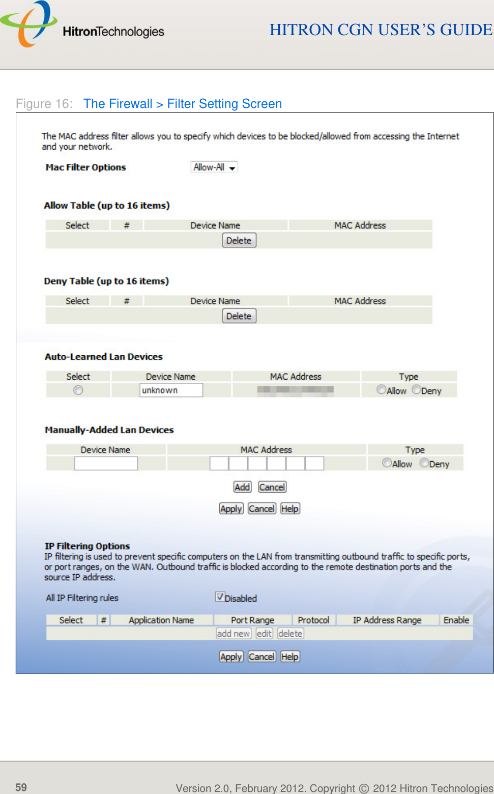
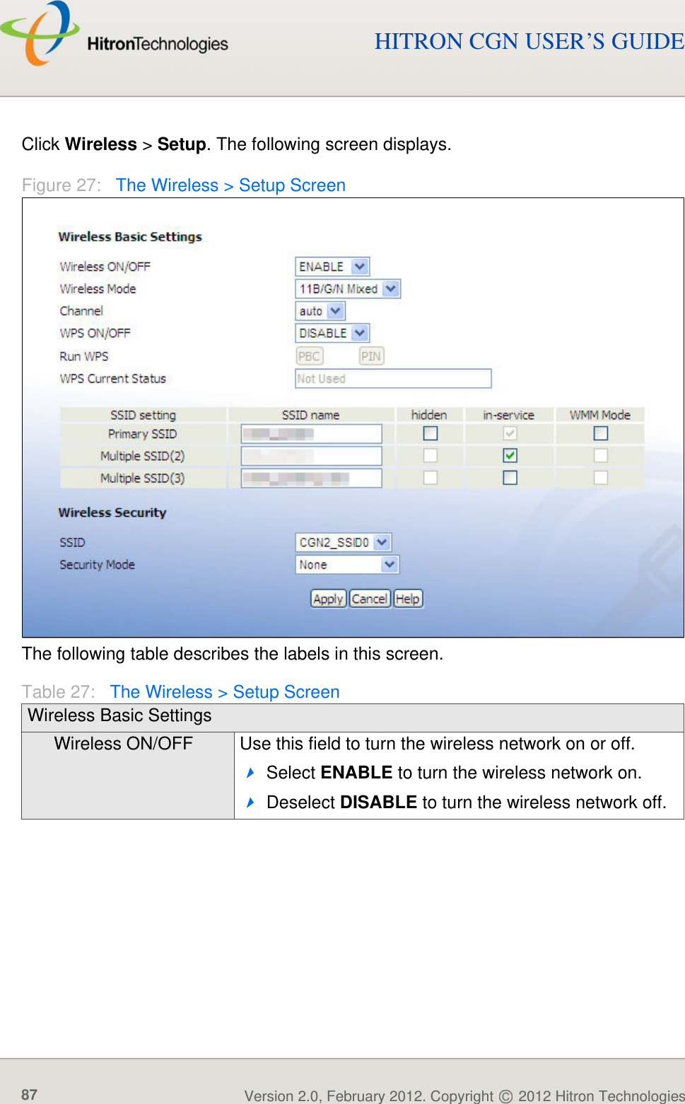
![FIREWALLVersion 2.0, February 2012. Copyright 2012 Hitron Technologies73Version 2.0, February 2012. Copyright 2012 Hitron Technologies73HITRON CGN USER’S GUIDEClick Firewall > DMZ. The following screen displays.Figure 22: The Firewall > DMZ ScreenThe following table describes the labels in this screen.Table 23: The Firewall > DMZ ScreenEnable DMZ Host Use this field to turn the DMZ on or off.Select the checkbox to enable the DMZ.Deselect the checkbox to disable the DMZ. Computers that were previously in the DMZ are now on the LAN.Connected Computers Click this to see a list of the computers currently connected to the CGN on the LAN. To add a connected computer to the DMZ, click its Add button and click Apply in the screen that displays.[...] IP Address [...] Enter the IP address of the computer that you want to add to the DMZ.Apply Click this to save your changes to the fields in this screen.Cancel Click this to return the fields in this screen to their last-saved values without saving your changes.Help Click this to see information about the fields in this screen.](https://usermanual.wiki/Hitron-TECHNOLOGIES/CGN01A/User-Guide-1663467-Page-73.png)