Hobbico TTX403 RADIO SYSTEM TRANSMITTER User Manual
Hobbico Inc RADIO SYSTEM TRANSMITTER
UserManual.wiki
>
Hobbico
>
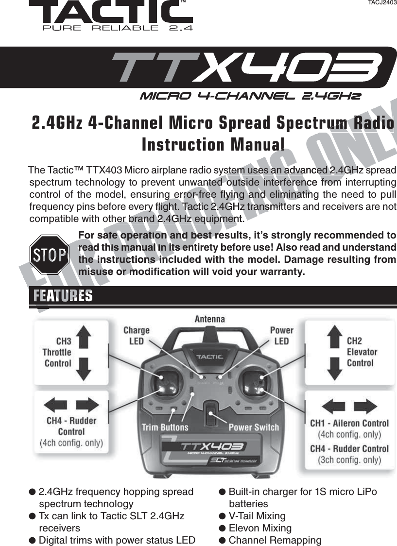
TTX403 User Manual
Users Manual
Navigation menu
Upload a User Manual
Namespaces
Wiki Guide
HTML
PDF
Info
Views
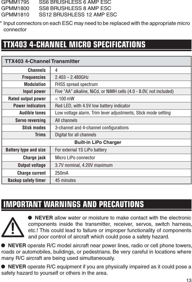
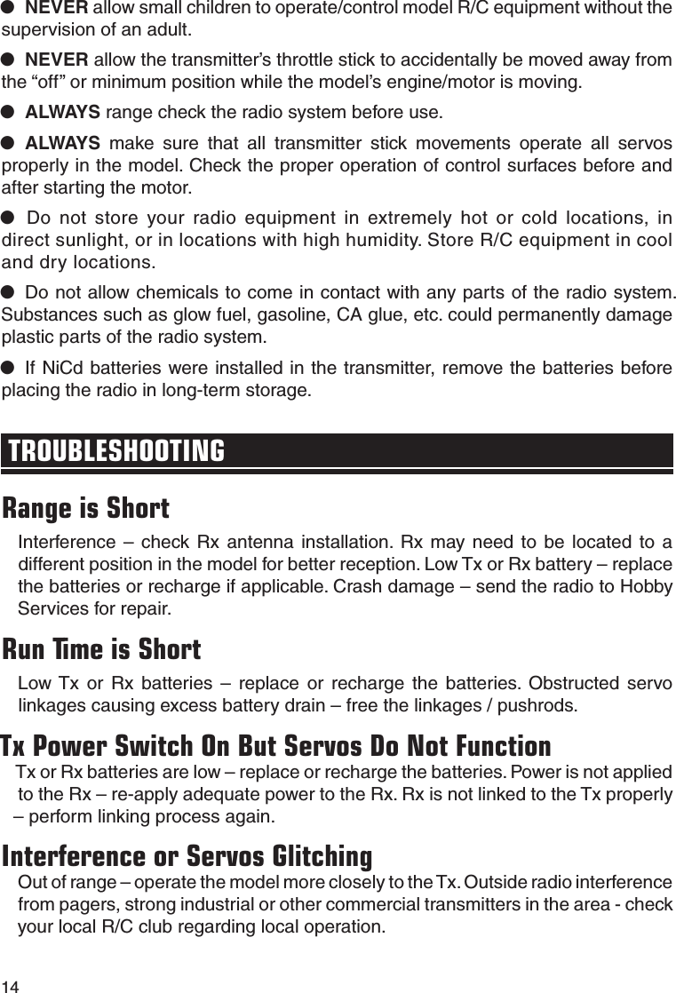
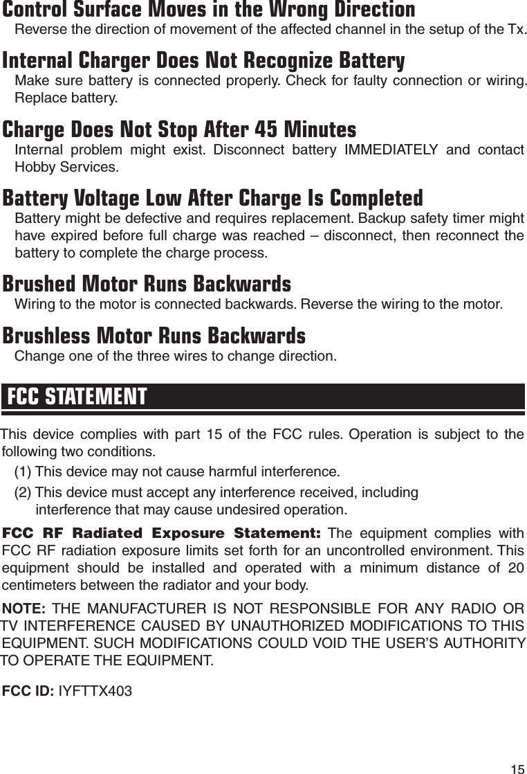
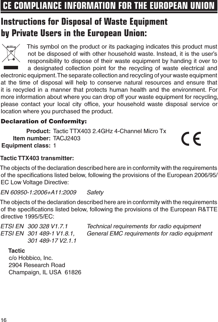
User Manual
Discussion / Help
Navigation