Users Manual
The Tactic™ TTX403 Micro airplane radio system uses an advanced 2.4GHz spread
spectrum technology to prevent unwanted outside interference from interrupting
control of the model, ensuring error-free fl ying and eliminating the need to pull
frequency pins before every fl ight. Tactic 2.4GHz transmitters and receivers are not
compatible with other brand 2.4GHz equipment.
For safe operation and best results, it’s strongly recommended to
read this manual in its entirety before use! Also read and understand
the instructions included with the model. Damage resulting from
misuse or modifi cation will void your warranty.
FEATURES
2.4GHz 4-Channel Micro Spread Spectrum Radio
Instruction Manual
™TACJ2403
● 2.4GHz frequency hopping spread
spectrum technology
● Tx can link to Tactic SLT 2.4GHz
receivers
● Digital trims with power status LED
● Built-in charger for 1S micro LiPo
batteries
● V-Tail Mixing
● Elevon Mixing
● Channel Remapping
FOR PROOFING ONL
ystem uses an advanced 2.4GHz system uses an advanced 2.4GHz s
wanted outside interference from wanted outside interference from
g error-free fl ying and eliminatingg error-free fl ying and eliminatin
ery fl ight. Tactic 2.4GHz transmitteery fl ight. Tactic 2.4GHz transmitt
her brand 2.4GHz equipment.her brand 2.4GHz equipmen
For safe operation and best reFor safe operation and best re
read this manual in its entread this manual in its ent
the instructions incthe instructions inc
misuse or momisuse or m
FOR
F
FEATURES
FOR
FOR
FOR
FOR
FO
OR
FO
FO
NG ONLY
rum Radio
al
2
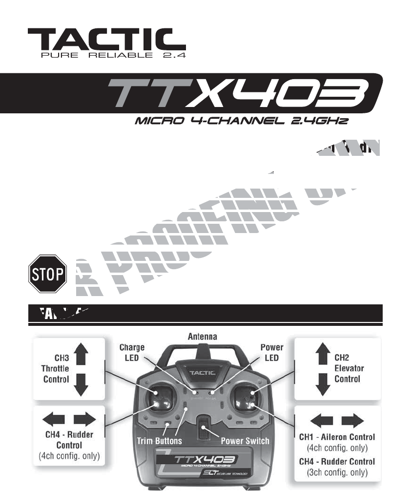
TTX403 TRANSMITTER (Tx)
The TTX403 4-Channel Micro airplane transmitter can be confi gured to operate
as a 3-channel or 4-channel Tx. When confi gured for 4-channel operation the
controls function like a normal Mode-2 transmitter with aileron + elevator on the
right stick, and throttle + rudder on the left stick.
Confi guring the Tx for 3-channel operation can help beginners concentrate on
throttle control with one hand and full airplane directional control with the other hand.
Here, the right stick operates elevator + rudder while the left stick will control the
throttle. The aileron function will still be active, and now be on the left stick, but aileron
control is often not needed for 3ch aircraft.
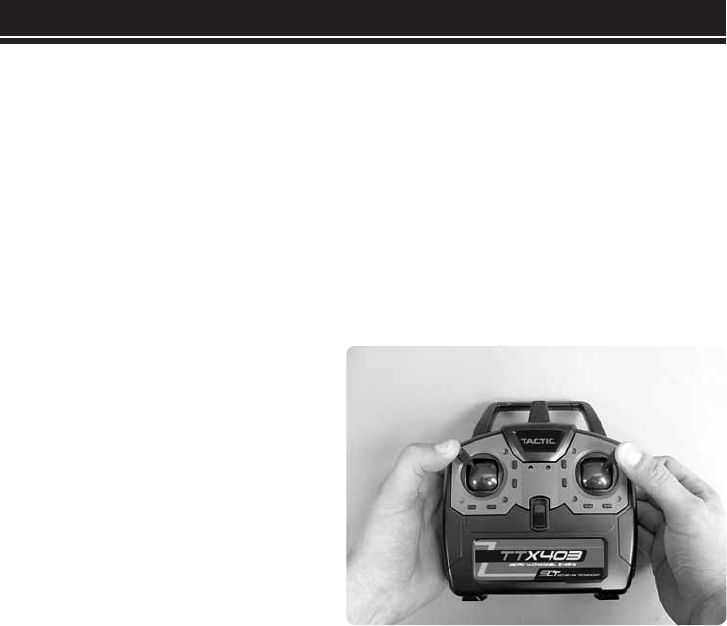
To change the TTX403 transmitter between 3ch and 4ch confi gurations:
1. Turn off the Tx power switch.
2. Move the right stick to the top-
right corner, and the left stick to
the top-left corner, and hold in
these positions.
3. Move the Tx power switch to the
on position. The power LED will
fl ash, accompanied by three
short tones from the Tx which
indicates the Tx confi guration
has been changed.
NOTE: Each time the Tx power switch is turned on you will hear either one
short tone if the Tx is in the 3ch configuration, or two short tones if the Tx is
in the 4ch configuration.
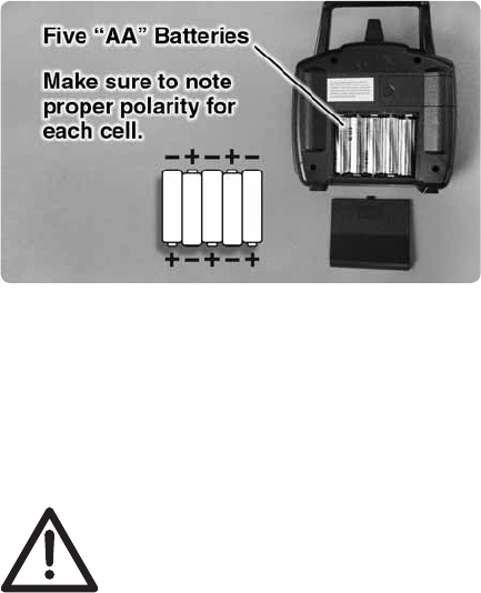
Input Power
Five “AA” batteries are required to power the Tx (not included with individual radio
systems). Non-rechargeable 1.5V alkaline, or 1.2V rechargeable nickel-cadmium
(NiCd) or nickel-metal hydride (NiMH) cells can be used. Do not mix cell types, old
and new cells, etc. See the SERVOS AND ACCESSORIES section on page 12 for
optional products available at local hobby retailers.
3
Slide the battery door down,
and insert the cells as shown.
Make sure to note proper
polarity for each cell. Close the
battery door.
Power LED and Low Battery Alarm
The red power LED should light when the power switch is moved upwards to the
on position. The Tx should have adequate power for fl ight when the LED is on
constantly. Anytime the LED begins to fl ash, accompanied by an audible tone, the
Tx battery voltage has dropped too low and operation of the model should NOT
be attempted!
WARNING! Never operate an R/C model with weak Tx batteries!
Reduced operational range and/or possible loss of control of the
aircraft could result. Replace weak alkaline batteries, or recharge
NiCd or NiMH batteries before attempting a fl ight!
If during a fl ight audible tones sound and the Tx LED starts to fl ash the Tx batteries
have become weak and the aircraft should be landed as soon as possible!
Aileron (Ch 1)
Controls the moveable surfaces at the trailing edge of the main wings to rotate the
airplane about the “roll” axis (an imaginary line which extends from the airplane’s
nose to the tail). Since every airplane is different, the direction of movement for
the aileron channel may need to be reversed so that moving the aileron stick to
the right will cause the airplane’s right aileron to defl ect up, thus causing the right
wing to drop and the airplane will bank to the right. Moving the aileron stick to the
left will cause the airplane’s left wing to drop and the airplane will bank to the left.
This is one important method for turning the aircraft. When the Tx is set to the 3ch
confi guration the aileron channel will not be used.
Elevator (Ch 2)
Controls the moveable horizontal surfaces on the airplane’s tail to rotate the airplane
about the “pitch” axis (an imaginary line extending through the center of both main
wings, from one wing tip to the other wing tip). The direction of movement for the
elevator channel may need to be reversed so that pulling the elevator stick back
(towards you) will cause the elevator to defl ect up, thus causing the nose of the
4
airplane to rise. Pushing the elevator stick forwards (away from you) will cause the
nose of the airplane to drop.
Throttle (Ch 3)
Controls the speed (R.P.M.) at which the motor operates. Pulling the throttle stick
back will cause the motor’s speed to decrease. Pushing the throttle stick forward
will cause the motor’s speed to increase.
Rudder (Ch 4)
Controls the side-to-side movement of the airplane’s tail and will rotate the airplane
about the “yaw axis” (an imaginary line from the top of the airplane’s fuselage to the
bottom of the fuselage, located near the center-point of the fuselage). The direction
of movement for the rudder channel may need to be reversed so that moving the
rudder stick to the right causes the rudder to defl ect to the right, thus causing the
nose of the airplane to point to the right. Moving the rudder stick to the left will cause
the nose of the airplane to turn left. When the Tx is set to the 3ch confi guration the
rudder will be controlled by the right stick. Otherwise, rudder is controlled with the
left stick.
Trims
All trims are digital in function. Two trim buttons are included for each of the main
controls, located adjacent to the respective stick. One trim button adjusts the
servo’s direction in one direction, and the other button to the opposite direction.
Briefl y pressing any trim button will adjust the center position of the respective
servo output in the appropriate direction and will be accompanied by an audible
tone. Pressing and holding any trim button will cause the servo output to move
repeatedly. A unique tone will sound when the servo reaches either end of the trim
limit, and at the channel’s center point.
During a fl ight, when the main sticks are released and spring back to center position
the aircraft should ideally not veer in any direction. If the aircraft does veer in a
particular direction, press the respective trim button until the aircraft maintains a
straight attitude on its own.
Reversing Channel Direction
The direction of movement for any of the four channels can be reversed electronically.
To change the direction of movement for any channel:
1. Switch off the Tx power switch.
2. Press and hold either trim button for the channel to be reversed.
3. Switch the Tx power switch on. The LED should fl ash to indicate the
movement for that channel has been reversed.
4. Repeat steps 1-3 to reverse the direction of any other channel as needed.
5. Switch the Tx power switch off.
5
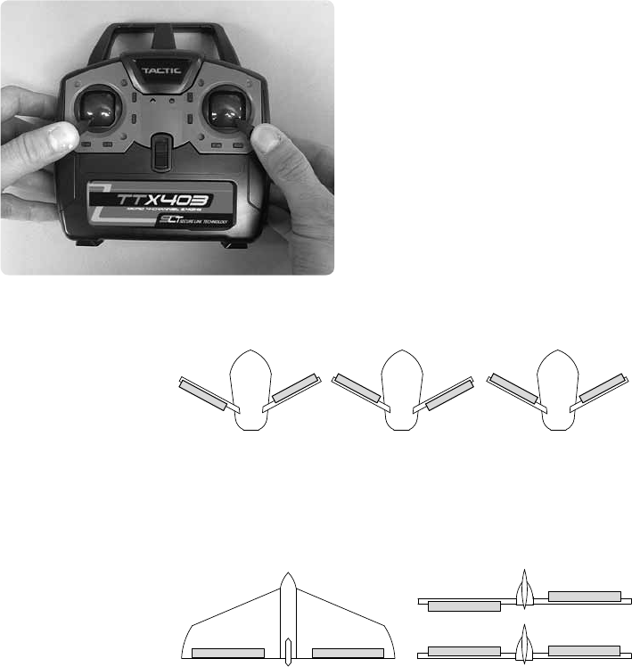
Elevon & V-Tail Mixing Functions
The TTX403 includes elevon and V-tail mixing functions, which can be turned on or
off. “Elevon” control consists of a mixture between the elevator and aileron channels,
and is useful for certain types of aircraft (such as a fl ying wing). “V-tail” control
consists of a mixture between the elevator and rudder channels and is useful for
aircraft which have a V-tail. The default setting for all mixing will be “off”. To change
the mix setting:
1. With the Tx power switch off, move
the right stick to the bottom-right
corner, and the left stick to the bottom-
left corner.
2. While holding the sticks in
these positions, turn the Tx power
switch ON.
3. The transmitter will emit three rapid
tones to confirm the programming
has been changed. The LED will
then flash once simultaneously with
one (3ch config) or two tones (4ch
config) during powerup. This single flash indicates that the transmitter is in
V-Tail mixing and the LED will remain solid afterwards.
V-Tail Mixing
Left Rudder
ch2 ch4 ch2 ch4 ch2 ch4
Right Rudder Up Elevator
4. To cancel V-tail mixing and activate elevon mixing, turn off the transmitter and
repeat the above procedure. When the LED fl ashes twice during powerup the
elevon mix is enabled and the LED will remain solid afterwards.
Elevon Mixing
Elevator Function
Aileron
Function
5. To cancel all mixes, repeat this procedure again. When the LED remains solid, all
mixes will be off.
6
Each time the mix setting is changed, be sure to check that all controls move in
the proper direction for the model. It may be necessary to change the setting of
the aileron, elevator, or rudder reversing on page 4 to achieve the proper throw
directions for the model. If the elevator and aileron functions or the rudder and
elevator functions appear reversed at the control surfaces, it may be necessary to
swap the channel 1 and 2 servo plug positions for the elevon mix or the channel 2
and 4 servo plug positions for the V-tail mix.
Electronic Speed Control (ESC)
If the model is electric powered, an optional ESC will be necessary to control speed
of the electric motor and to divert power to the receiver and servos. Connect the
receiver plug on the ESC to the slot marked CH3 (throttle) on the receiver. Center
the transmitter’s throttle trim and follow the ESC instructions for proper operation
and connection of the power battery.
Glow Engines
If the model is powered by a glow engine, a switch harness and 4-cell battery
(4.8V) will be necessary to power the receiver and servos. See the SERVOS AND
ACCESSORIES section for suggested options.
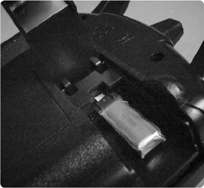
Built-In 1S LiPo Charger
A 1S LiPo charger is built into the TTX403 transmitter itself. This charger is designed
specifi cally for charging a micro 1S 3.7V LiPo cell which has a micro connector.
Charge current is rated at 250mAh, with a maximum charge voltage of 4.20V.
Charging will begin automatically when the battery is connected, and automatically
stop when full charge is detected.
1. Make sure the Tx power
switch is in the off position.
2.
Looking at the rear of the Tx,
slide open the charger door
by moving it to the right.
3. Connect the 1S LiPo battery
to the socket inside the
battery door. When a proper
connection has been made
and the battery is being
charged, the green “CHARGE”
LED will illuminate.
4. When charge is complete
the green CHARGE LED will
turn off.
7
IMPORTANT WARNINGS REGARDING LIPO BATTERY USE
NEVER ATTEMPT TO CARE FOR LITHIUM-POLYMER (LiPo) CELLS
IN THE SAME WAY AS OTHER BATTERY TYPES! LiPo cells are much
more sensitive and volatile than NiCd or NiMH batteries. Misuse and
overcharge can quickly result in LiPo cells getting hot and/or swelling,
which could lead to VIOLENT EXPLOSION AND/OR FIRE and serious personal
injury and property damage.
● NEVER attempt to recharge other battery types except 1S LiPo cells with this
built-in charger.
● NEVER continue to charge or use LiPo cells if they start to swell, and become
overly warm to the touch. Failure to follow this guideline could cause the battery
to become hot and explode or ignite!!
● ALWAYS disconnect the battery from the charger immediately if the battery
becomes hot! Allow the battery to cool before use.
● NEVER allow water, moisture or foreign objects into the Tx/charger.
● NEVER leave the room where a battery is being charged.
● NEVER place the Tx/charger or battery on a fl ammable surface or near a
fl ammable object during the charge process. Keep away from carpets, cluttered
workbenches, etc.
● ALWAYS have a “class D” fi re extinguisher available when handling LiPo batteries.
● If a LiPo cell leaks fl uid, do not get fl uid on the skin, in the eyes or mouth, etc. If
you make contact with fl uid from a LiPo battery, rinse the affected area well with
water and seek immediate medical care.
LINK THE RECEIVER TO THE TRANSMITTER
This link ensures sole communication between the two, and prevents other
transmitters from controlling the model. If it’s necessary to re-link the board to the
transmitter:
1. Switch on the Tx.
2. Connect the battery to the Rx. See SERVOS AND ACCESSORIES on page
12 for recommendations.
3. The Rx LED on the Rx will turn on, indicating the Rx is bound to the Tx.
4. Test for proper Tx / Rx functionality in the next section. If the system did not
become properly linked, repeat steps 1-3 above.

8
SYSTEM CHECK AND OPERATION
WARNING! During all pre-fl ight preparations with the aircraft on the
ground, make sure the throttle stick remains at the minimum position
and do not stand the Tx upright on the ground. Carefully lay the Tx on its
back on the ground to prevent it from falling over and possibly dislodging
the throttle stick from the low position which would create a safety hazard. Make
sure all devices are properly mounted inside the model, and all wiring connections
are secure to prevent them from easily becoming dislodged during fl ight. For safety
it’s best to check the system with the propeller removed from the aircraft.
1. Once all connections are made, check the general operation of the radio
and all other components before attempting a fl ight.
2. Move the Tx throttle stick to the minimum (idle) position.
3. Turn on the Tx, and then the Rx.
4. Make sure all controls are operating in the proper direction. If any servo is
turning in the wrong direction, change the reversing for that particular channel.
5. With both sticks at center position, move the trims for the aileron, elevator,
and rudder channels so each respective control surface is perfectly aligned
with the main surface. For example: When the aileron trim is at center it’s
best that the trailing edge of the aileron is aligned with the trailing edge of
the wing itself (not above or below the wing’s trailing edge).
6. Make sure that movements of the throttle stick result in an equal adjustment
of the motor R.P.M. in the model.
7. Perform a “range check”. The “range” is the safe operating distance
from the Tx to the Rx, and should be 150 meters. With the assistance of
another person, place the aircraft on the ground and walk 100 feet (30m)
away from the model. With the Tx pointed directly at the model, operate
the transmitter’s controls, and ensure the movement of all surfaces are
according to the movement of the transmitter.
8. Anytime power is to be removed from the radio system, it’s important to shut
down power in the aircraft fi rst. Otherwise, the aircraft could become out
of control and cause a safety hazard! Move the throttle stick to minimum
position to shut down the ESC. Once the propeller has stopped rotating,
shut off the ON/OFF power switch in the model, and disconnect the power
battery from the ESC in electric airplanes. Then turn off the power switch in
the Tx.
9
FLYING THE AIRCRAFT
1. Once all setup procedures have been confi rmed, and power has been
removed from the model and transmitter, re-attach the propeller to the model.
IMPORTANT: Be careful to stay clear from moving propellers!!
2. Make sure the airplane’s power batteries are fully charged.
3. Move the Tx throttle stick to minimum position, then switch on the Tx power
switch. Turn on the power switch in the model.
4. During the fi rst fl ight, it might be necessary to re-trim the aileron, elevator,
and rudder channels to allow the airplane to sustain level hands-off fl ight. If
further adjustments are required on the ground, beware that the on-board
brushed ESC will still be active (if used).
5. When the fl ight is completed, remove power from the system as described
before. Shut down power to the Rx Control Board fi rst, then the transmitter.
SAFETY GUIDE
The Academy of Model Aeronautics (AMA) has established an Offi cial Safety Code.
Model fl ying MUST be in accordance with this Code in order for AMA Liability
Protection to apply. All questions relating to the AMA Safety Code, liability insurance
program, and other offi cial AMA information can be attained from the AMA:
Academy of Model Aeronautics
5161 East Memorial Drive
Muncie, Indiana 47302
(765) 287-1256 – Business
(765) 289-4248 – Fax
(800) 435-9262 – Membership Services
http://www.modelaircraft.org
http://www.modelaircraft.org/fi les/Memanual.PDF
10
2009 Offi cial Academy of Model Aeronautics National
Model Aircraft Safety Code Effective January 1, 2006
The AMA’s Offi cial 2009 Safety Code includes the following regarding the use of
model aircraft:
GENERAL
1. A model aircraft shall be defi ned as a non-human-carrying device capable of
sustained fl ight in the atmosphere. It shall not exceed limitations established
in this code and is intended to be used exclusively for recreational or
competition activity.
2. The maximum takeoff weight of a model aircraft, including fuel, is 55 pounds,
except for those fl own under the AMA Experimental Aircraft Rules.
3. I will abide by this Safety Code and all rules established for the fl ying
site I use. I will not willfully fl y my model aircraft in a reckless and/or
dangerous manner.
4. I will not fl y my model aircraft in sanctioned events, air shows, or model
demonstrations until it has been proven airworthy.
5. I will not fl y my model aircraft higher than approximately 400 feet above
ground level, when within three (3) miles of an airport without notifying the
airport operator. I will yield the right-of-way and avoid fl ying in the proximity of
full-scale aircraft, utilizing a spotter when appropriate.
6. I will not fl y my model aircraft unless it is identifi ed with my name and
address, or AMA number, inside or affi xed to the outside of the model aircraft.
This does not apply to model aircraft fl own indoors.
7. I will not operate model aircraft with metal-blade propellers or with gaseous
boosts (other than air), nor will I operate model aircraft with fuels containing
tetranitromethane or hydrazine.
8. I will not operate model aircraft carrying pyrotechnic devices which explode
or burn, or any device, which propels a projectile of any kind. Exceptions
include Free Flight fuses or devices that burn producing smoke and are
securely attached to the model aircraft during fl ight. Rocket motors up to
a G-series size may be used, provided they remain fi rmly attached to the
model aircraft during fl ight. Model rockets may be fl own in accordance
with the National Model Rocketry Safety Code; however, they may not be
launched from model aircraft. Offi cially designated AMA Air Show Teams
(AST) are authorized to use devices and practices as defi ned within the Air
Show Advisory Committee Document.
9. I will not operate my model aircraft while under the infl uence of alcohol or
within eight (8) hours of having consumed alcohol.
11
10. I will not operate my model aircraft while using any drug which could
adversely affect my ability to safely control my model aircraft.
11. Children under six (6) years old are only allowed on a fl ight line or in a fl ight
area as a pilot or while under fl ight instruction.
12. When and where required by rule, helmets must be properly worn and
fastened. They must be OSHA, DOT, ANSI, SNELL or NOCSAE approved or
comply with comparable standards.
RADIO CONTROL
1. All model fl ying shall be conducted in a manner to avoid overfl ight of
unprotected people.
2. I will have completed a successful radio equipment ground-range check
before the fi rst fl ight of a new or repaired model aircraft.
3. I will not fl y my model aircraft in the presence of spectators until I become a
profi cient fl ier, unless I am assisted by an experienced pilot.
4. At all fl ying sites a safety line or lines must be established, in front of which
all fl ying takes place. Only personnel associated with fl ying the model
aircraft are allowed at or in front of the safety line. In the case of air shows or
demonstrations a straight safety line must be established. An area away from
the safety line must be maintained for spectators. Intentional fl ying behind
the safety line is prohibited.
5. I will operate my model aircraft using only radio-control frequencies currently
allowed by the Federal Communications Commission (FCC). Only individuals
properly licensed by the FCC are authorized to operate equipment on
Amateur Band frequencies.
6. I will not knowingly operate my model aircraft within three (3) miles of any
preexisting fl ying site without a frequency-management agreement. A
frequency-management agreement may be an allocation of frequencies for
each site, a day-use agreement between sites, or testing which determines
that no interference exists. A frequency-management agreement may exist
between two or more AMA chartered clubs, AMA clubs and individual
AMA members, or individual AMA members. Frequency-management
agreements, including an interference test report if the agreement indicates
no interference exists, will be signed by all parties and copies provided to
AMA Headquarters.
7. With the exception of events fl own under offi cial AMA rules, excluding
takeoff and landing, no powered model may be fl own outdoors closer than
25 feet to any individual, except for the pilot and the pilot’s helper(s) located
at the fl ight line.

12
8. Under no circumstances may a pilot or other person touch a model aircraft in
fl ight while it is still under power, except to divert it from striking an individual.
9. Radio-controlled night fl ying is limited to low-performance model aircraft (less
than 100 mph). The model aircraft must be equipped with a lighting system
which clearly defi nes the aircraft’s attitude and direction at all times.
10. The operator of a radio-controlled model aircraft shall control it during the
entire fl ight, maintaining visual contact without enhancement other than by
corrective lenses that are prescribed for the pilot. No model aircraft shall be
equipped with devices which allow it to be fl own to a selected location which
is beyond the visual range of the pilot.
FREE FLIGHT
1. I will not launch my model aircraft unless I am at least 100 feet downwind of
spectators and automobile parking.
2. I will not fl y my model aircraft unless the launch area is clear of all individuals
except my mechanic, offi cials, and other fl iers.
3. I will use an effective device to extinguish any fuse on the model aircraft after
the fuse has completed its function.
ACCESSORIES
Servos and Accessories
TACL0324 Tactic TR324 3-Channel Receiver
TACL0625 Tactic TR625 6-Channel Receiver
TACL0424 Tactic TR424 4-Channel Receiver
TACL1424 Tactic TR1424 4-Channel Receiver with 2 Servos
TACM0021 Tactic TSX21 Linear Servo Actuator
FUTM4503 FPC10M Micro Servo/Battery Connector
FUTM4504 AEC-29 Micro Y-Harness 75mm, 3 in.
TACM0019 TSX019 Ultra Pico 1.9g Servo
Batteries and Chargers
FUGP4308 Fuji® AA Alkaline Batteries (8)
GPMP0760 ElectriFly LiPo 1S 3.7V 140mAh 20C
GPMP0770 ElectriFly LiPo 1S 3.7V 250mAh 20C
Electronic Speed Controls *
FPWM0206 FLIGHTPOWER 6A LIPO BL ESC BEC
FPWM0210 FLIGHTPOWR 10A LIPO BL ESC BEC
13
GPMM1795 SS6 BRUSHLESS 6 AMP ESC
GPMM1800 SS8 BRUSHLESS 8 AMP ESC
GPMM1810 SS12 BRUSHLESS 12 AMP ESC
* Input connectors on each ESC may need to be replaced with the appropriate micro
connector
TTX403 4-CHANNEL MICRO SPECIFICATIONS
TTX403 4-Channel Transmitter
Channels 4
Frequencies 2.403 – 2.480GHz
Modulation FHSS spread spectrum
Input power Five “AA” alkaline, NiCd, or NiMH cells (4.0 - 8.0V, not included)
Rated output power < 100 mW
Power indicators Red LED, with 4.5V low battery indicator
Audible tones Low voltage alarm, Trim lever adjustments, Stick mode setting
Servo reversing All channels
Stick modes 3-channel and 4-channel configurations
Battery type and size For external 1S LiPo battery
Charge jack Micro LiPo connector
Output voltage 3.7V nominal, 4.20V maximum
Charge current 250mA
Backup safety timer 45 minutes
Built-in LiPo Charger
Trims Digital for all channels
IMPORTANT WARNINGS AND PRECAUTIONS
● NEVER allow water or moisture to make contact with the electronic
components inside the transmitter, receiver, servos, switch harness,
etc.! This could lead to failure or improper functionality of components
and poor control of aircraft which could pose a safety hazard.
● NEVER operate R/C model aircraft near power lines, radio or cell phone towers,
roads or automobiles, buildings, or pedestrians. Be very careful in locations where
many R/C aircraft are being used simultaneously.
● NEVER operate R/C equipment if you are physically impaired as it could pose a
safety hazard to yourself or others in the area.

14
● NEVER allow small children to operate/control model R/C equipment without the
supervision of an adult.
● NEVER allow the transmitter’s throttle stick to accidentally be moved away from
the “off” or minimum position while the model’s engine/motor is moving.
● ALWAYS range check the radio system before use.
● ALWAYS make sure that all transmitter stick movements operate all servos
properly in the model. Check the proper operation of control surfaces before and
after starting the motor.
● Do not store your radio equipment in extremely hot or cold locations, in
direct sunlight, or in locations with high humidity. Store R/C equipment in cool
and dry locations.
● Do not allow chemicals to come in contact with any parts of the radio system.
Substances such as glow fuel, gasoline, CA glue, etc. could permanently damage
plastic parts of the radio system.
● If NiCd batteries were installed in the transmitter, remove the batteries before
placing the radio in long-term storage.
TROUBLESHOOTING
Range is Short
Interference – check Rx antenna installation. Rx may need to be located to a
different position in the model for better reception. Low Tx or Rx battery – replace
the batteries or recharge if applicable. Crash damage – send the radio to Hobby
Services for repair.
Run Time is Short
Low Tx or Rx batteries – replace or recharge the batteries. Obstructed servo
linkages causing excess battery drain – free the linkages / pushrods.
Tx Power Switch On But Servos Do Not Function
Tx or Rx batteries are low – replace or recharge the batteries. Power is not applied
to the Rx – re-apply adequate power to the Rx. Rx is not linked to the Tx properly
– perform linking process again.
Interference or Servos Glitching
Out of range – operate the model more closely to the Tx. Outside radio interference
from pagers, strong industrial or other commercial transmitters in the area - check
your local R/C club regarding local operation.

15
Control Surface Moves in the Wrong Direction
Reverse the direction of movement of the affected channel in the setup of the Tx.
Internal Charger Does Not Recognize Battery
Make sure battery is connected properly. Check for faulty connection or wiring.
Replace battery.
Charge Does Not Stop After 45 Minutes
Internal problem might exist. Disconnect battery IMMEDIATELY and contact
Hobby Services.
Battery Voltage Low After Charge Is Completed
Battery might be defective and requires replacement. Backup safety timer might
have expired before full charge was reached – disconnect, then reconnect the
battery to complete the charge process.
Brushed Motor Runs Backwards
Wiring to the motor is connected backwards. Reverse the wiring to the motor.
Brushless Motor Runs Backwards
Change one of the three wires to change direction.
FCC STATEMENT
This device complies with part 15 of the FCC rules. Operation is subject to the
following two conditions.
(1) This device may not cause harmful interference.
(2) This device must accept any interference received, including
interference that may cause undesired operation.
FCC RF Radiated Exposure Statement: The equipment complies with
FCC RF radiation exposure limits set forth for an uncontrolled environment. This
equipment should be installed and operated with a minimum distance of 20
centimeters between the radiator and your body.
NOTE: THE MANUFACTURER IS NOT RESPONSIBLE FOR ANY RADIO OR
TV INTERFERENCE CAUSED BY UNAUTHORIZED MODIFICATIONS TO THIS
EQUIPMENT. SUCH MODIFICATIONS COULD VOID THE USER’S AUTHORITY
TO OPERATE THE EQUIPMENT.
FCC ID: IYFTTX403
16
CE COMPLIANCE INFORMATION FOR THE EUROPEAN UNION
Instructions for Disposal of Waste Equipment
by Private Users in the European Union:
This symbol on the product or its packaging indicates this product must
not be disposed of with other household waste. Instead, it is the user’s
responsibility to dispose of their waste equipment by handing it over to
a designated collection point for the recycling of waste electrical and
electronic equipment. The separate collection and recycling of your waste equipment
at the time of disposal will help to conserve natural resources and ensure that
it is recycled in a manner that protects human health and the environment. For
more information about where you can drop off your waste equipment for recycling,
please contact your local city offi ce, your household waste disposal service or
location where you purchased the product.
Declaration of Conformity:
Product: Tactic TTX403 2.4GHz 4-Channel Micro Tx
Item number: TACJ2403
Equipment class: 1
Tactic TTX403 transmitter:
The objects of the declaration described here are in conformity with the requirements
of the specifi cations listed below, following the provisions of the European 2006/95/
EC Low Voltage Directive:
EN 60950-1:2006+A11:2009 Safety
The objects of the declaration described here are in conformity with the requirements
of the specifi cations listed below, following the provisions of the European R&TTE
directive 1995/5/EC:
ETSI EN 300 328 V1.7.1 Technical requirements for radio equipment
ETSI EN 301 489-1 V1.8.1, General EMC requirements for radio equipment
301 489-17 V2.1.1
Tactic
c/o Hobbico, Inc.
2904 Research Road
Champaign, IL USA 61826
17
CE COMPLIANCE INFORMATION FOR THE EUROPEAN UNION
The associated regulatory agencies of the following countries recognize the noted certifications
for this product as authorized for sale and use.
UK DE DK BG SE FI FR
EE LV LT PL CZ SK HU
RO SI AT IT ES PT IE
NL LU MT CY GR
1-YEAR LIMITED WARRANTY * U.S.A. & Canada
Tactic warrants this product to be free from defects in materials and workmanship
for a period of one (1) year from the date of purchase. During that period, Tactic will,
at its option, repair or replace without service charge any product deemed defective
due to those causes. You will be required to provide proof of purchase (invoice or
receipt). This warranty does not cover damage caused by abuse, misuse, alteration
or accident. If there is damage stemming from these causes within the stated
warranty period, Tactic will, at its option, repair or replace it for a service charge not
greater than 50% of its then current retail list price. Be sure to include your daytime
telephone number in case we need to contact you about your repair. This warranty
gives you specifi c rights. You may have other rights, which vary from state to state.
For service on your Tactic product, send it post paid and insured to:
HOBBY SERVICES Ph: (217) 398-0007
3002 N. Apollo Dr., Suite 1 (9:00am – 5:00pm CST, M–F)
Champaign, IL 61822
E-mail: hobbyservices@hobbico.com
tacticrc.com
● This product is suitable only for people of 14 years and older. This is not a toy!
● WARNING: CHOKING HAZARD - May contain small parts. Keep away from
children under 3 years. Please retain packaging for future reference.
● No part of this manual may be reproduced in any form without prior permission.
● The contents of this manual are subject to change without prior notice.
● Tactic is not responsible for the use of this product.

© 2013 Hobbico,
® Inc.
TACJ2403Made in China
™