Hoist Fitness Hoise System Cl 2408 Users Manual 2408_Cover
HOIST-CL2408
CL-2408 to the manual a374bcc2-d094-4757-9886-ac497e11344a
2015-02-05
: Hoist-Fitness Hoist-Fitness-Hoise-Fitness-System-Cl-2408-Users-Manual-407576 hoist-fitness-hoise-fitness-system-cl-2408-users-manual-407576 hoist-fitness pdf
Open the PDF directly: View PDF ![]() .
.
Page Count: 41
Note: Both Serial Number and Model Number are Required when Ordering Parts
August 2000
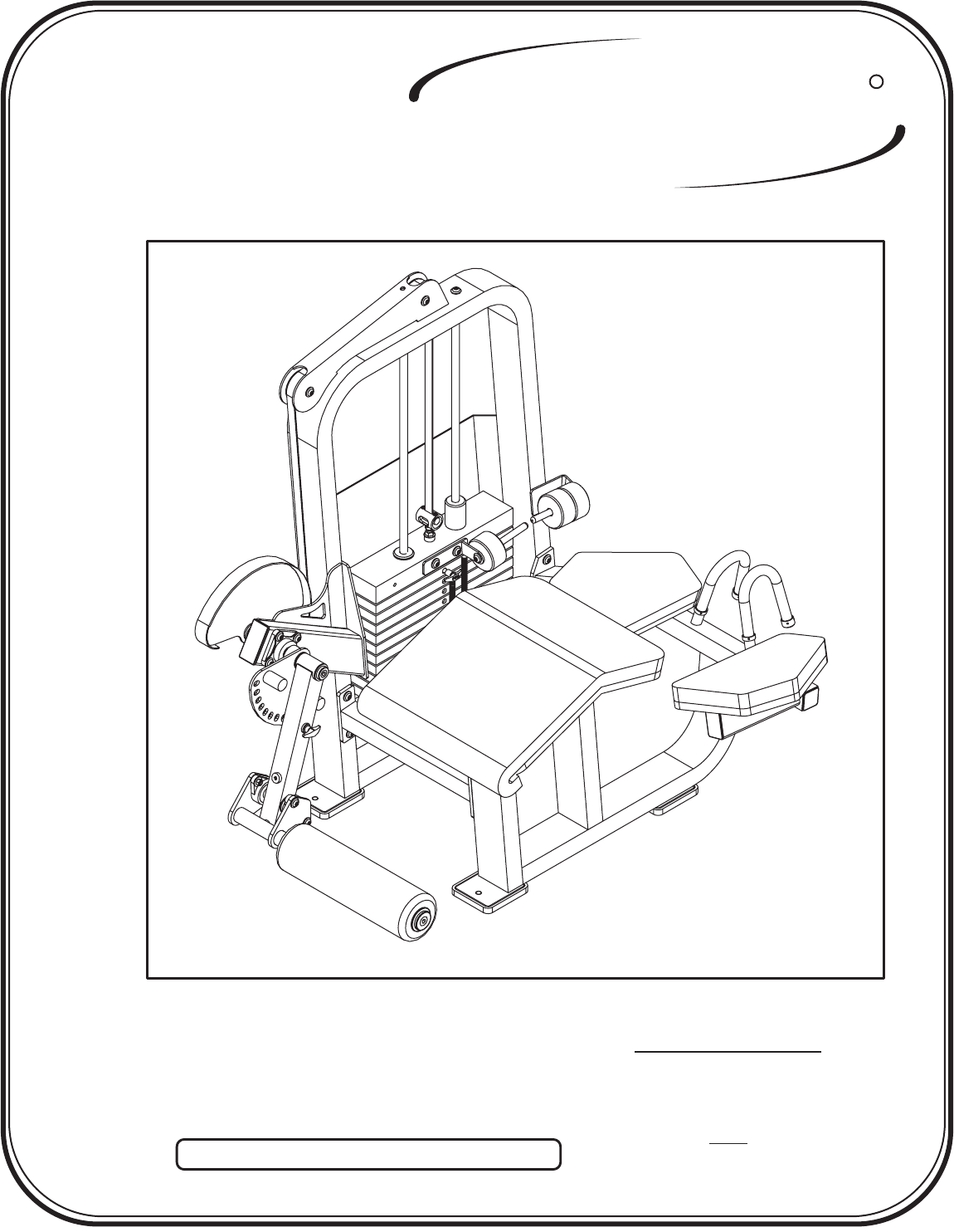
OWNERS MANUAL
RECORD SERIAL NUMBER HERE
Customer Service
Fa x
(800) 548-5438
(619) 578-7676
(619) 578-9558
CL-2408
FITNESS SYSTEMS
R
HOIST

CONTENTS
ASSEMBLY
INSTRUCTIONS
FITNESS SYSTEMS
R
HOIST
INSTRUCTIONS (Step 1) .............................................................
FRAME ASSEMBLY (Step 2) ........................................................
PARTS LISTING ............................................................................
HARDWARE LISTING ..................................................................
BOLT SIZING CHART ..................................................................
WASHER SIZING CHART ............................................................
WEIGHT RATIOS .........................................................................
WEIGHT TRAINING TIPS ...........................................................
WEIGHT TRAINING EXERCISE LOG ......................................
DECAL PLACEMENTS .................................................................
GENERAL MAINTENANCE INFORMATION............................
LIMITED WARRANTY ..................................................................
2
4
21
22
24
25
26
28
30
32
37
40
Page - 1 2408 Assembly

ASSEMBLY
INSTRUCTIONS
INSTRUCTIONS
Page - 22408 Assembly
Standard Allen Wrench Set
(2.5mm, 3/32” - 5/16”)
Crescent Wrench
Belt Tensioning Wrench
(Hoist Tool SM374)
Rubber Mallet
Tape Measure
Step 1
TOOLS REQUIRED
Before beginning assembly please take the time to read the
instructions thoroughly. Please use the catalog in this manual to
make sure that all parts have been included in your shipment.
Use only Hoist replacement parts when servicing. Failure
to do so will void your warranty and could result in personal
injury.
Hoist equipment is designed to provide the smoothest, most
effective exercise motion possible. After assembly, you should
check all functions to ensure correct operation. If you
experience problems, first recheck the assembly instructions to
locate any possible errors made during assembly. If you are
unable to correct the problem, call your authorized Hoist dealer.
Be sure to have your serial number and this catalog when calling.
When all parts have been accounted for, continue on to Step 2.
When ordering use the part number and description from the
catalog.
FITNESS SYSTEMS
R
HOIST

FITNESS SYSTEMS
R
HOIST
Page - 3 2408 Assembly
ASSEMBLY
INSTRUCTIONS
ASSEMBLY
INSTRUCTIONS
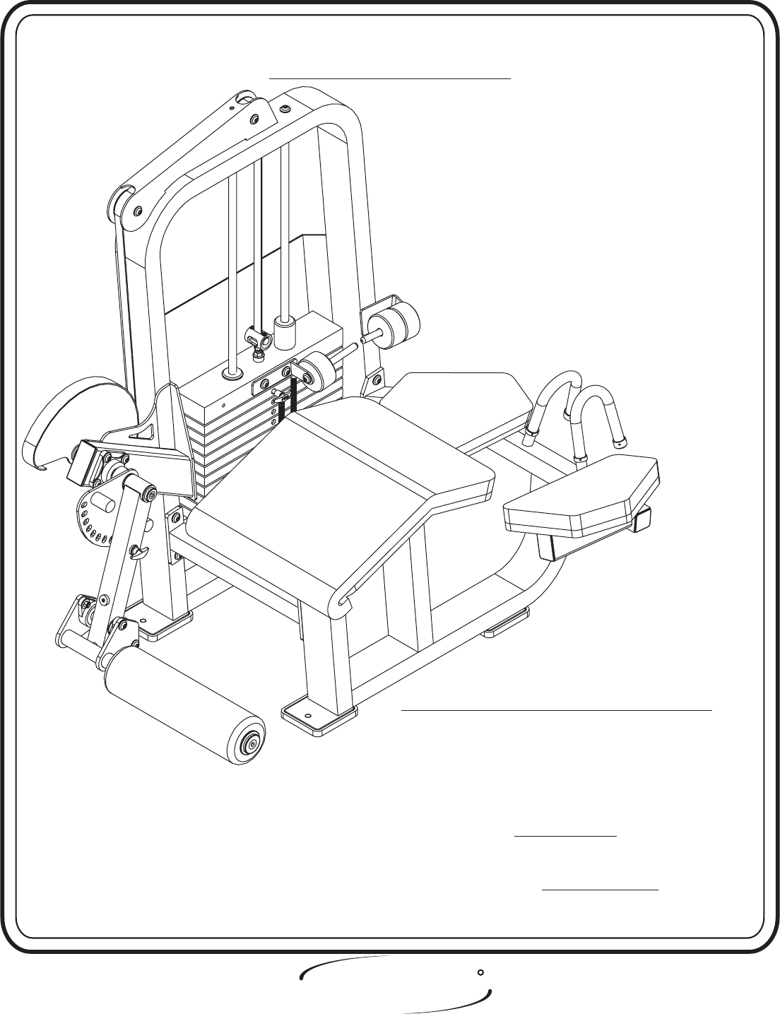
FRAME ASSEMBLY
Page - 42408 Assembly
Step 2
FITNESS SYSTEMS
R
HOIST
FACTORY INSTALLATION INSTRUCTION ONLY
1. ALL THREADED HOLES SHOULD BE TAPPED,
EXCEPT INSERTS.
2. ALL CALLED OUT INSERTS MUST BE INSTALLED BEFORE
ANY ASSEMBLY.
3. PUT A DROP OF ON BOLTS IF
NECESSARY.
4. IF NECESSARY APPLY TO ALL
BEARINGS.
BLUE LOCTITE 242
GREEN LOCTITE 680

ASSEMBLY
INSTRUCTIONS
FRAME ASSEMBLY
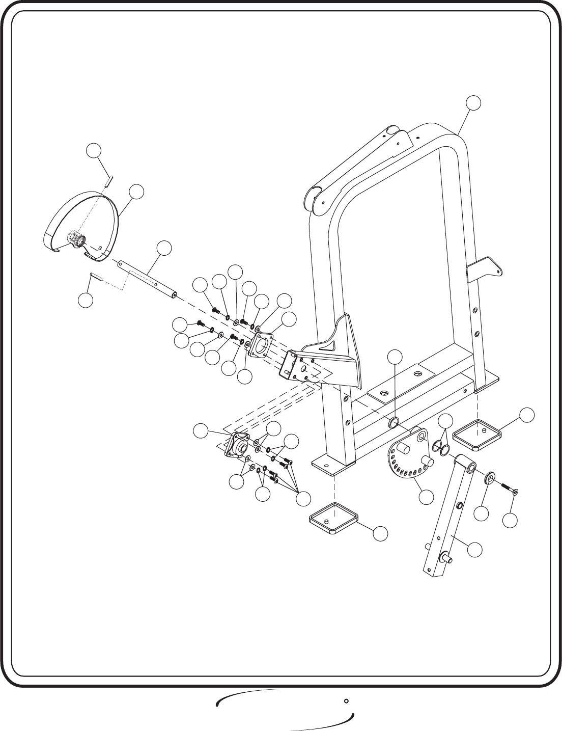
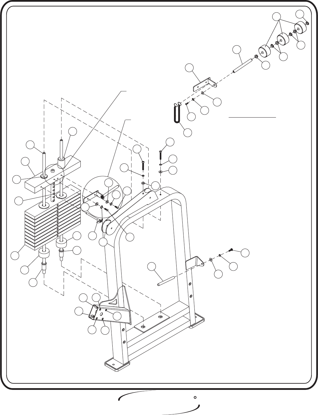
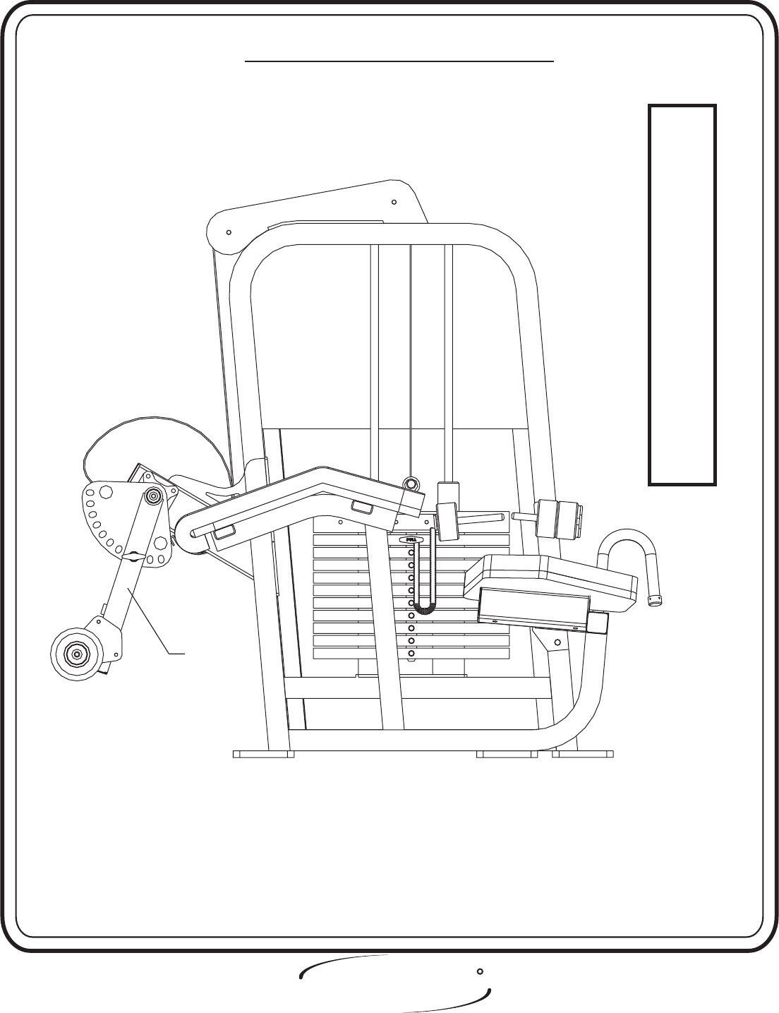
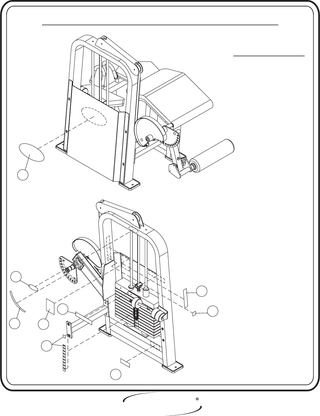
In this step attach two Flange Bearings to the Weight Cage. Make sure to
put zerk fitting facing down on Flange Bearings. Next attach the 1” Dia.
CRS to the Cam Assembly (Large). Slide the other side of the 1” Dia. CRS
through the Flange Bearings and the Weight Cage. Attach the Range of
Motion, Extension Tube Assembly, and a Red Iodized Aluminum Cap to
the 1” Dia. CRS. bolts only, they will be tightened later.
Lift Machine to position Rubber Feet.
Hand Tighten
Step 2a
2 - Range of Motion
4 - Extension Tube Assembly
6 - Cam Assembly (Large)
7 - Weight Cage
12 - 1” Dia. CRS
23 - Rubber Feet
34 - Red Iodized Aluminum Cap
36 - Black Plastic Ring
Part Descriptions
D - 3/8” x 1 1/4” Flat Head Screw
E - 3/8” x 1 1/4” Button Head Screw
T - 3/8” Lock Washer (black)
W - 3/8” x 2 Open Roll Pin
X - 1” Dia. X .8mm Shims
AH - Flange Bearing
BE - 3/8” Flat Washer
Hardware Descriptions
FITNESS SYSTEMS
R
HOIST
Page - 5 2408 Assembly
ASSEMBLY
INSTRUCTIONS
Page - 62408 Assembly
FITNESS SYSTEMS
R
HOIST
7
12
T
BE
E
AH
BE
E
BE
E
BE
AH
E
36
2
D
WBE
6
W
34
23
E
T
T
T
BE
T
T
23
X
SEE PRE-ASSEMBLED PARTS ON PAGE 20
BEFORE ASSEMBLED MACHINE.
4

ASSEMBLY
INSTRUCTIONS
FRAME ASSEMBLY
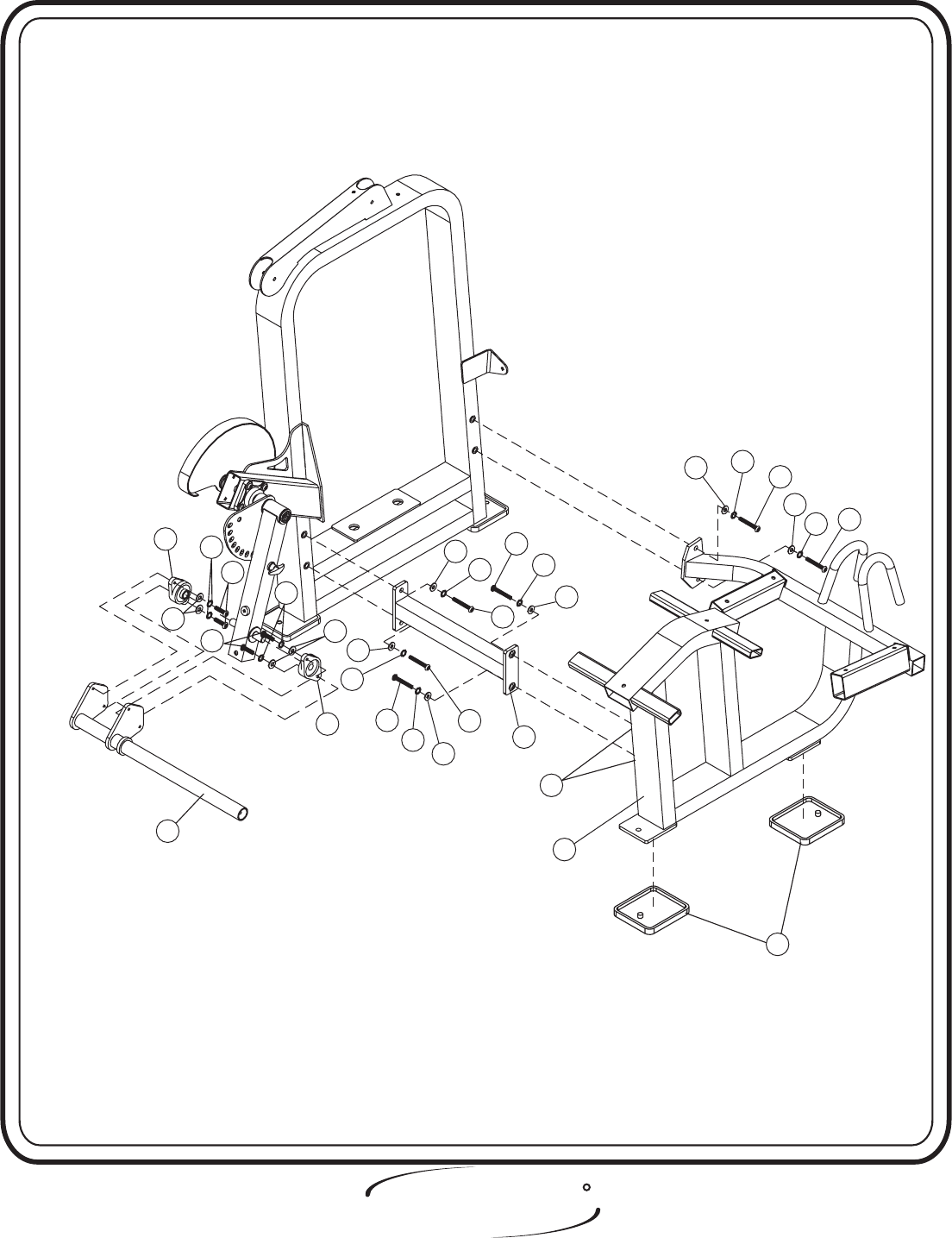
In this step, start by attaching the Cross Tube Assembly to the Weight Cage,
then attach the Seated frame to the Cross Tube Assembly and the Weight Cage.
Next insert the Bearings (BF) in the Extension Tube Assembly then align the Shin
bar Assembly to the Bearings and secure. Make sure to put zerk fitting facing
down. bolts only, they will be tightened later.Hand Tighten Lift Machine to
position Rubber Feet.
Step 2b
5 - Shin Bar Assembly
8 - Seated Frame Assembly
9 - Cross Tube Assembly
13 - Shaft
23 - Rubber Foot Pad
Part Descriptions
A - 1/2” x 1 1/2” Button Head Screw
H - 3/8-16” x 1” Button Head Screw
N - 1/2” Lock Washer
P - 1/2” Flat Washer
T - 3/8” Internal Lock Washer
AJ - 1/2” Insert
AR - Flange Bearing (014-0008004)
BE - 3/8” Flat Washer
Hardware Descriptions
FITNESS SYSTEMS
R
HOIST
Page - 7 2408 Assembly
ASSEMBLY
INSTRUCTIONS
Page - 82408 Assembly
FITNESS SYSTEMS
R
HOIST
A
N
P
P
N
A
BE
N
A
A
N
P
9
5
N
A
P
NA
AJ
23
P
H
T
BE
AR
T
AR P
AR
8
1/2” INSERTS ARE BEHIND
ASSEMBLY
INSTRUCTIONS
FRAME ASSEMBLY
Step 2c
In this step start by pressing two Guide Rod Bushings into the
Weight Cage. Take the two 3” x 1” I.D. Bumpers and place them over the
two holes in the bottom of the Now slide the Guide Rods into
the holes. Make sure to lube the Guide Rods with Spindle Oil. Next slide
on ten(10) 20 LBS Intermediate Weight Plates and one(1) 15 LBS
Aluminum Top Plate onto the Guide Rods, and bolt into place. Make sure
the Weight Stack and its Guide Rods are sitting level. Next, attach the
5/8” Dia. x 6 13/32” Rod to the Center RH BRK ( Add-On). Secure the
Center RH BRK (Add-On) to the . Slide on
three 5 LBS. Add-On Weights and attach the 5/8” Dia. x 6 13/32” Rod to
the . Attach bigger end of the Selector Pin Lanyard to the
, and the other end to the Weight Selector Pin.
Then bolts including all previously hand tightened boltsWrench tighten .
Weight Cage.
15 LBS Aluminum Top Plate
Weight Cage
Center RH BRK ( Add-On)
FITNESS SYSTEMS
R
HOIST
3 - Center RH BRK (Add-On)
10 - Guide Rod
15 - 5/8” Dia. x 6 13/32” (Add-On)
Rod
19 - 15 lbs Aluminum Top Plate
32 - 11 Plate Selector Stem
33 - 20 lbs Intermediate Weight
37 - Add On Weight Bushing
Part Descriptions
H - 3/8” x 1 Button Head Screw
G - 5/16” x 1” Button Head Cap Screw
J - 3/8” x 2 3/4” Button Head Cap Screw
Q - 3/8” Flat Washer
R - 3/8” Lock Washer
V - 5/16” Flat Washer
T - 3/8” Internal Lock Washer
AK - Guide Rod Bushing
AL - 3” x 1” I.D. x 1 1/2” THK Bumper
AM - Guide Bearing
AN - Guide Bearing
AP - Selector Pin Lanyard
AT - Weight Selector Pin
AU - 5 lbs Add-On Weight
AW - Insert
BB - 3/8” x 1” Button Head Screw (white zinc)
BC - 3/8” Split Washer
BE - 3/8” Flat Washer
BJ - 5/16” Internal Lock Washer
Hardware Descriptions
Page - 9 2408 Assembly
ASSEMBLY
INSTRUCTIONS
2408 Assembly Page - 10
FITNESS SYSTEMS
R
HOIST
G
10
19
AM
33
AL
32
AL
AK
AT
BB
R
Q
15
AP
H
J
BE
3
AU
FOR ASSEMBLY INSTRUCTION
SEE PAGE 18
FOR ASSEMBLY INSTRUCTION
SEE PAGE 18
A-1
FOR CLARITY SEE A-1FOR CLARITY SEE A-1
AW
V
BJ
G
V
BJ
BC
T
J
Q
Q
BC
AW
AW AW
AW
AW
AN
AK
15
37
37
37
37

ASSEMBLY
INSTRUCTIONS
FITNESS SYSTEMS
R
HOIST
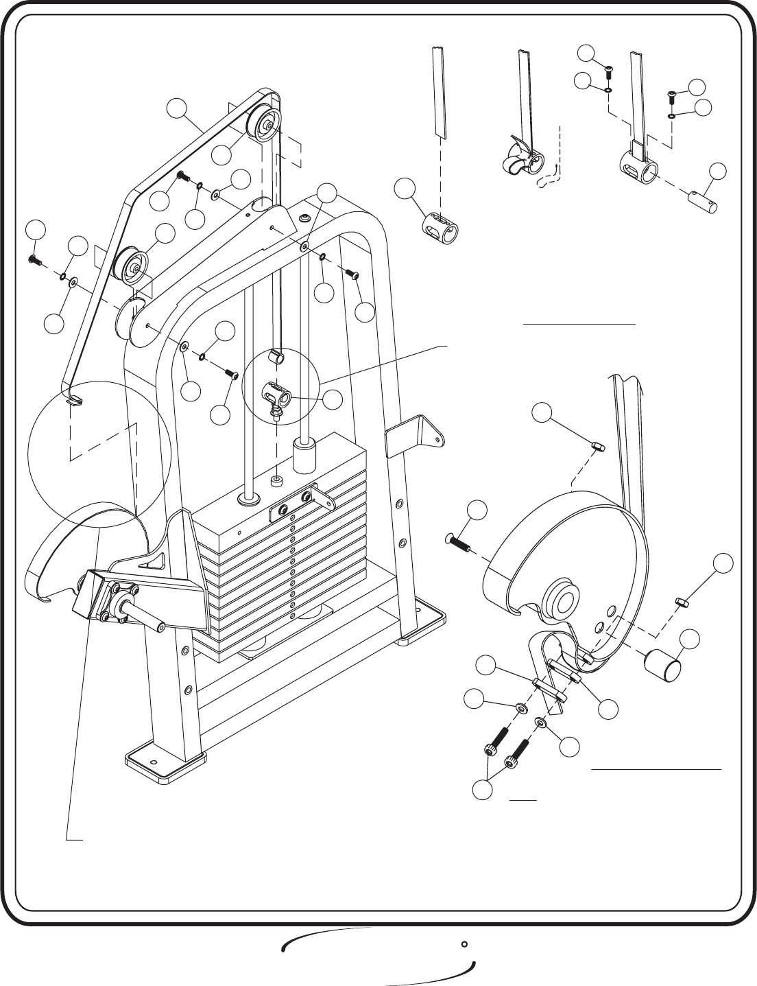
1 - Belt Assembly
14 - 3/4” x 2 1/16” CRS
16 - Clamp
20 - Cam Belt 74” x 15/16” x 1/8”
22 - 1 1/2” Dia. Delrin Stop
35 - 1 5/8” x 2 1/16” lg DOM
Part Descriptions
C - 1/2” x 1” Flat Head Cap Screw
F - 1/4” x 1” Button Head Screw
M - 3/8” x 3/4” Button Head Screw
Q - 3/8” Flat Washer
R - 3/8” Lock Washer
S - 1/4” Lock Washer
Z - 1/4-20 x 1 1/2” Socket Head Screw
AS - 3 1/4” Pulley
AY - 1/4” Lock Nut
Hardware Descriptions
In this step start by attaching the Belt Assembly to the Weight
Assembly(prior to attaching the Cam Belt). Next slide the Cam Belt
through the Roller Bracket on the top of the Weight Cage. Then use a
Seat Clamp On tool to secure the two 3 1/4” Pulleys to the
under the Cam Belt.
A
bolts.Wrench tighten
Weight Cage
Slide the Cam Belt into the top slot of 1 5/8” Dia. x 2
1/16” Lg. Dom. (Fig. 1) Loop the end of the Cam Belt and feed it back up
through the slot, keeping the loop open. (Fig 2) Next, slide the 3/4” x 2
1/16 CRS through the Cam belt and line up the holes, then secure to the 1
5/8” Dia. X 2 1/16” Lg. Dom.(Fig. 3). ttaching the Cam Stopper to the
Cam Assembly. Next, attach the belt by bringing it around the Cam and in
between the Belt Clamps. Then wrap the cam belt down and around the
Belt Clamps and above another Belt clamp and secure all the Clamps
together.
FRAME ASSEMBLY
Step 2d
Page - 11 2408 Assembly
ASSEMBLY
INSTRUCTIONS
2408 Assembly Page - 12
FITNESS SYSTEMS
R
HOIST
20
AS
M
R
Q
AS
R
Q
M
M
R
Q
M
R
Q1
C
B-2
B-1
FOR BELT ASSEMBLY SEE B-2FOR BELT ASSEMBLY SEE B-2
FOR BELT ASSEMBLY SEE SX145 B-1FOR BELT ASSEMBLY SEE SX145 B-1
Z
22
S
S
16
16
AY
AY
FIGURE 1FIGURE 1 FIGURE 3FIGURE 3FIGURE 2FIGURE 2
14
S
F
F
S
35
NOTE: 1. BELT SMOOTH SIDE DOWN, ALWAYS
FOR TWO TOP PULLEYS AND CAM.
SMOOTH SIDE TO WRAP AROUND
BELT RETAINER SHAFT
3. INSURE DELRIN STOP IS SECURED IN
HOLE CLOSEST TO BELT CLAMP
2. WHEN TIGHTENING THE CLAMPS
(44) TO THE BELT DO NOT EXCEED
60 IN. LBS.

ASSEMBLY
INSTRUCTIONS
FITNESS SYSTEMS
R
HOIST
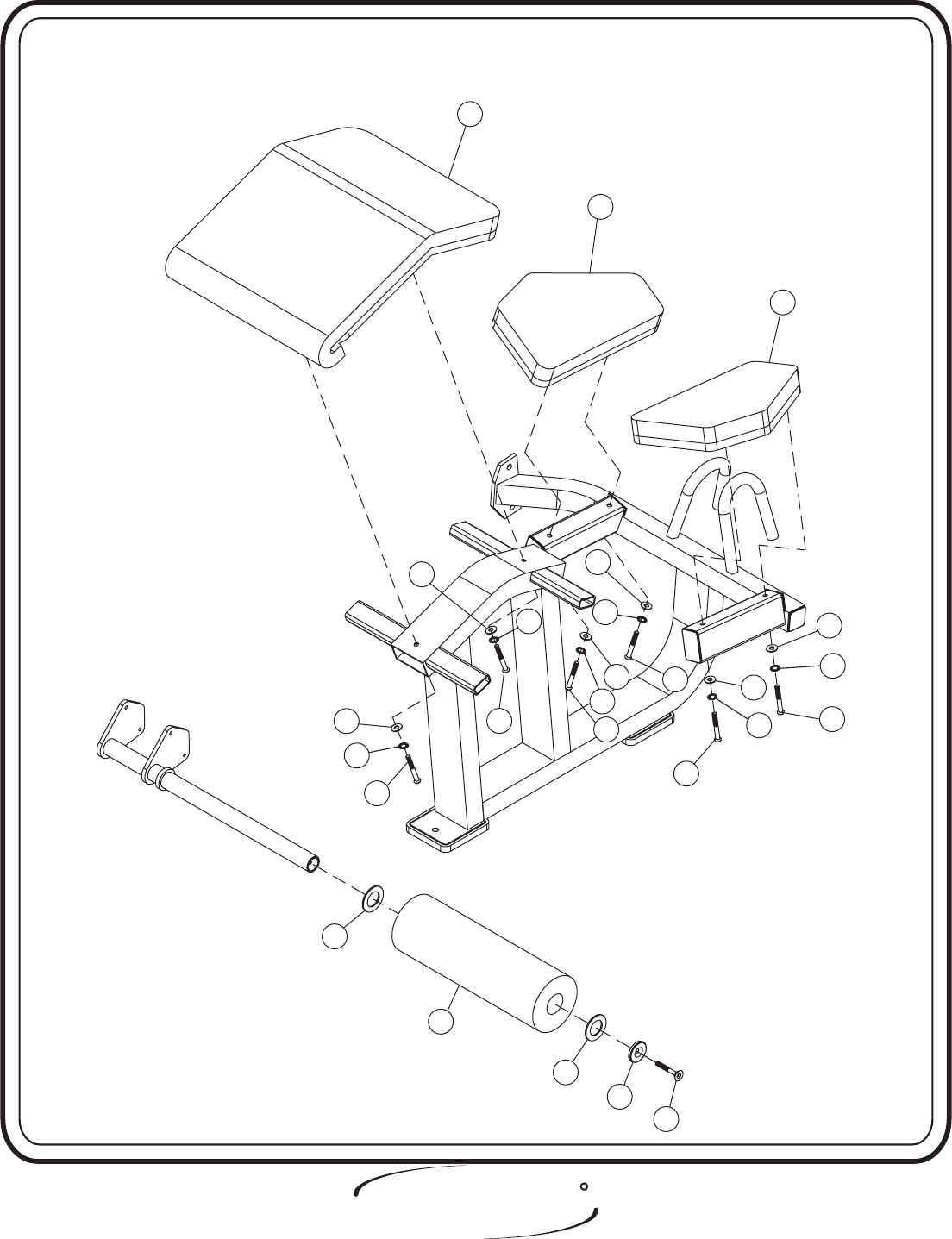
24 - Plastic Fender Washer
28 - Upholstery Pad
29 - Upholstery Pad
30 - Upholstery Pad
31 - 5” Dia. x 17.25 lg Roller
Part Descriptions
D - 3/8” x 1 1/4” Flat Head Screw
K - 5/16” x 2 3/4” Hex Head Cap Screw
L - 5/16” x 3 3/4” Hex Cap Screw
U - 5/16” Flat Washer
AV - Aluminum Cap
BD - 5/16” Internal Lock Washer
Hardware Descriptions
In this step start by attaching the 5” Dia. x 17.25 lg Roller to the
Shin Bar Assembly. Next, attach the Upholstery Pads the Seated Frame
Assembly bolts.Wrench tighten.
Page - 13 2408 Assembly
FRAME ASSEMBLY
Step 2e
ASSEMBLY
INSTRUCTIONS
2408 Assembly Page - 14
FITNESS SYSTEMS
R
HOIST
28
30
29
U
K
U
KL
U
U
LU
L
BD
L
24
31
24
AV
D
U
BD
BD
BD
BD
BD

ASSEMBLY
INSTRUCTIONS
FITNESS SYSTEMS
R
HOIST
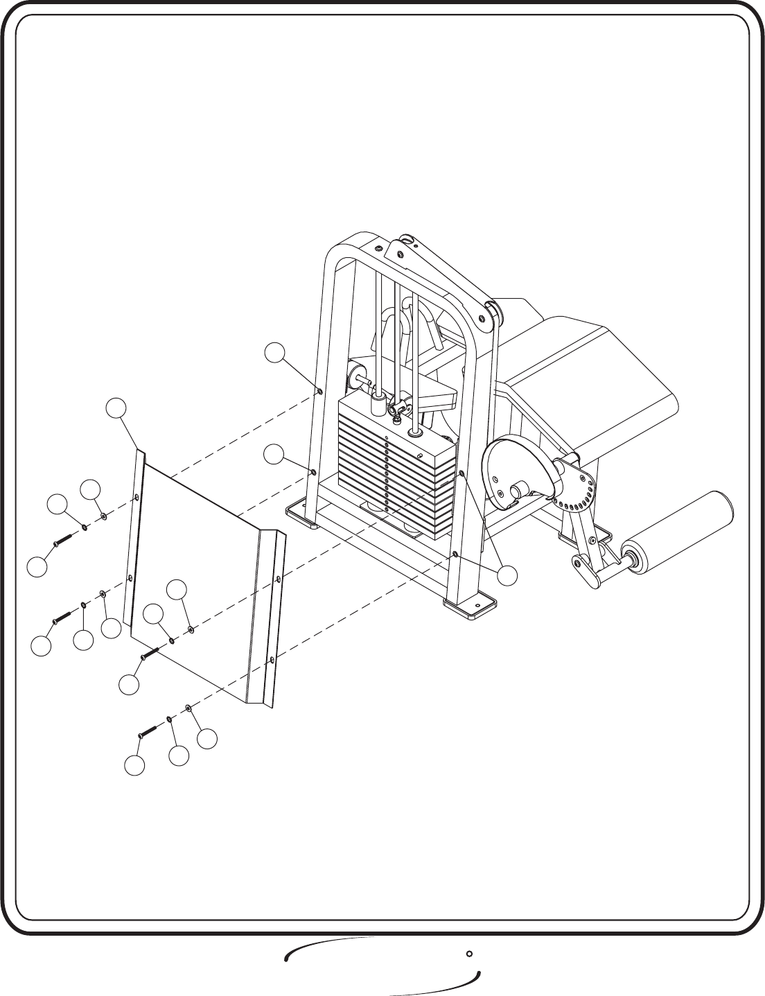
18 - Shield
Part Descriptions
A - 1/2” x 1 1/2” Button Head Screw
P - 1/2” Flat Washer
N - 1/2” Lock Washer
AJ - Insert
Hardware Descriptions
Attach the Shield to the Weight Cage. boltsWrench tighten .
Page - 15 2408 Assembly
FRAME ASSEMBLY
Step 2f
ASSEMBLY
INSTRUCTIONS
2408 Assembly Page - 16
FITNESS SYSTEMS
R
HOIST
18
P
N
A
N
P
A
A
AJ
N
P
N
A
P
AJ
AJ

ASSEMBLY
INSTRUCTIONS
FITNESS SYSTEMS
R
HOIST
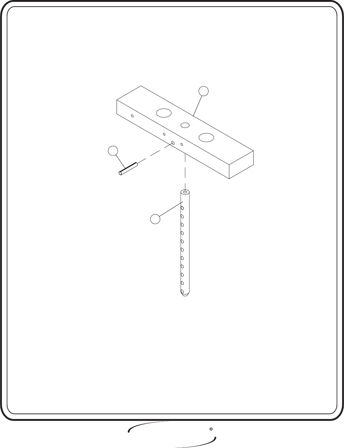
19 - 15 LBS. Aluminum Top Plate
32 - 11 Plate Selector Stem
Part Descriptions
Y - 7/16” x 3” Open Roll Pin
Hardware Descriptions
Slide the Plate Selector Stem up into the 15 LBS Aluminum Top
Plate and secure with a 7/16” x 3” Open Roll Pin. boltsWrench tighten .
Page - 17 2408 Assembly
FRAME ASSEMBLY
Step 2g
ASSEMBLY
INSTRUCTIONS
2408 Assembly Page - 18
FITNESS SYSTEMS
R
HOIST
19
Y
32

ASSEMBLY
INSTRUCTIONS
FITNESS SYSTEMS
R
HOIST
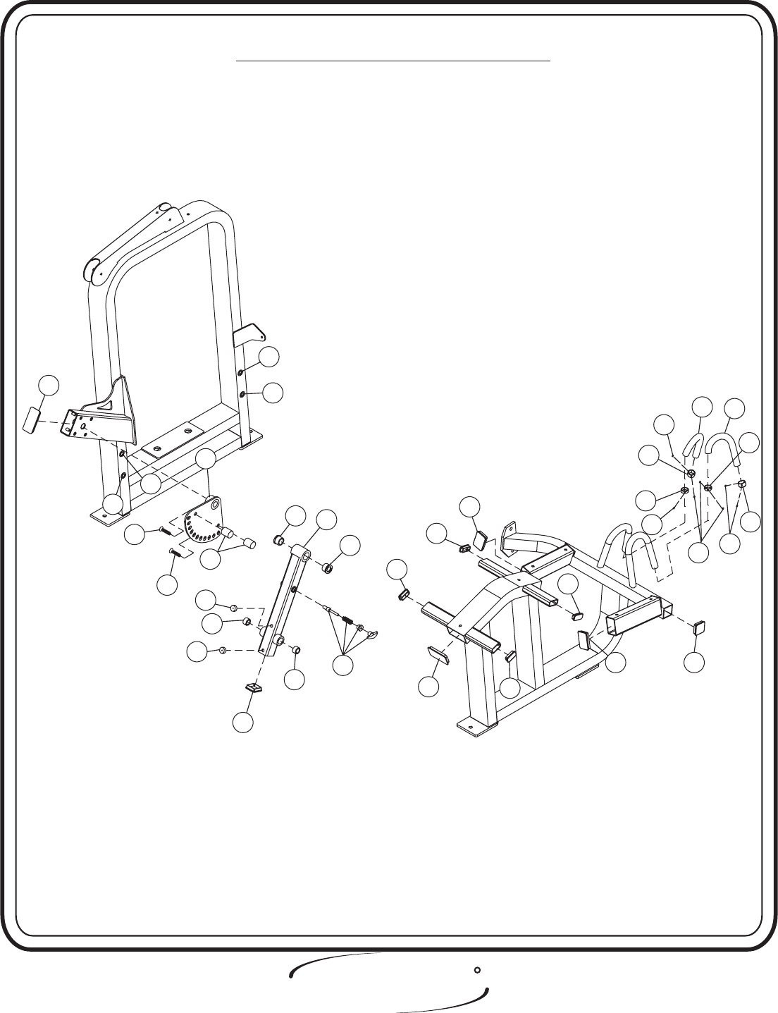
2 - Range of Motion
4 - Extension Rube
11 - 1/2” Pullpin (Hex Head)
21 - 1 1/4” Dia. Delrin
27 - Bumper Stoppper
Part Descriptions
C - 1/2” x 1” Flat Head Cap Screw
AA - 2” x 4” End Cap (Vertical H)
AB - 2” x 3” End Cap (Vertical H)
AC - 2” x 2” End Cap
AD - 1” x 2” End Cap
AE - 1.175 O.D. x 15/16 I.D. x 15.125 Lg Grip
AF - Bushing
AJ - Insert
AR - Radial Bearing
AX - 2” x 4” End Cap (Horizontal H)
AZ - 1 1/4” dia. x 3/8” Aluminum Ring
BA - 1 1/4” dia. x 3/4” Aluminum Cap
BK - #10-32 Set Screw
Hardware Descriptions
In this step start by pressing in two(2) Bushings, two(2) Radial
Bearings, two(2) Bumper Stoppers, one(1) End Cap, and secure the 1/2”
Pullpin (Hex Head) into the Extension Tube Assembly. Next, secure
two(2) 1 1/4” Dia. Delrins to the Range of Motion. Slide on two(2)
Aluminum Rings, two(2) Grips on the arms of the Seated Frame Assembly,
then secure two(2) Aluminum Caps on the end of the Arms. Then slide
the Grip flush with the Aluminum Cap and slide the Aluminum Ring flush
with the Grip and secure. Then attach the End Caps to both the Seated
Frame and the Weight Cage. boltsWrench tighten .
Page - 19 2408 Assembly
FRAME ASSEMBLY
Step 2h
ASSEMBLY
INSTRUCTIONS
2408 Assembly Page - 20
FITNESS SYSTEMS
R
HOIST
AA
C
27
21
4
2
27
AR
AC
AR
11
AD
AD
AB
AX AD
AD
AB AC
BK
AE
PRE-ASSEMBLED PARTS
AJ
AJ
AJ
AJ
AF
C
AF
AE
BA
AZ
AZ
BK
BK
BK
BA

FITNESS SYSTEMS
R
HOIST
PART LISTING
Page - 21 2408 Assembly
ASSEMBLY
CATALOG
Key # Qty. Part Number Description
1 1 26-STD-SX145 Belt Assembly
2 1 26-STD-SX146 Range of Motion
3 1 26-STD-SX155 Center RH BRK(Add-On)
4 1 26-STD-SX164 Extension Tube Assy.
5 1 26-STD-SX168 Shin Bar Assy.
6 1 26-STD-SX504 Cam Assembly (Large)
7 1 26-STD-SX615 Weight Cage
8 1 26-STD-SX616 Seated Frame Assembly
9 1 26-STD-SX617 Cross Tube Assy.
10 2 26-STD-SG135 Guide Rod
11 1 26-STD-SM129 1/2" Pullpin (Hex Head)
12 1 26-STD-SM289 1" Dia. CRS
14 1 35-STD-SM294 3/4" x 2 1/16" CRS
15 2 26-STD-SM295 5/8 Dia. X 6 13/32" (Add On Rod)
16 2 26-STD-SP467 Clamp
18 1 26-STD-SSH167 Shield
19 1 26-STD-SWTOP11 15 lbs. Aluminum Top Plate
20 1 15-BLT-1516 Cam Belt 74" x 15/16" x 1/8"
21 2 26-STD-PLAS133 1 1/2" Dia. Delrin
22 1 26-STD-PLAS193 1 1/4" Dia. Delrin
23 4 26-STD-PLAS195 Rubber Foot Pad
24 2 26-STD-PLAS144 Plastic Fender Washer
27 2 19-PAD-1 Bumper Stopper
28 1 26-STD--SU12253219 Upholstery PAD
29 1 26-STD-SU1016136R Upholstery PAD
30 1 26-STD-SU10161316L Upholstery PAD
31 1 26-STD-SUR517-1 5" Dia. x 17.25 lg. Roller
32 1 26-STD-SW112 11 Plates Selector Pin Stem
33 10 26-STD-SW104 20 lbs. Intermediate Weight
34 1 26-STD-SM239 Red Iodize Aluminum Cap
35 1 26-STD-SM293 1 5/8" x 2 1/16" lg. Tube
36 1 26-STD-PLAS178 Black Plastic Ring
37 6 26-STD-PLAS210 Add On Weight Bushing

2408 Assembly Page - 22
FITNESS SYSTEMS
R
HOIST
HARDWARE LISTING
ASSEMBLY
CATALOG
Key # Qty. Part Number Description
A 10 11-BTN-12112WZ 1/2-13" x 1 1/2" Button Head Screw
C 3 11-FLA-121WZ 1/2-13" x 1" Flat Head Cap Screw
D 2 11-FLA-38114WZ 3/8-16" x 1 1/4" Flat Head Screw
E 8 11-BTN-38114 3/8-16" x 1 1/4" Button Head Screw
F 2 11-BTN-141 1/4-20" x 1" Button Head Screw
G 2 11-BTN-5161 5/16-18" x 1" Button Head Cap Screw
H 5 11-BTN-381 3/8-16" x 1" Button Head Screw
J 2 11-BTN-38234WZ 3/8-16" x 2 3/4" Button Head Cap Screw
K 2 11-HEX-516234WZ 5/16-18" x 2 3/4" Hex Head Cap Screw
L 4 11-HEX-516334WZ 5/16-18" x 3 3/4" Hex Cap Screw
M 4 11-BTN-3834WZ 3/8-16" x 3/4" Button Head Screw
N 10 13-LOK-12INT 1/2-13" Lock Washer
P 4 13-FLT-12SAEWZ 1/2" Flat Washer
Q 12 13-FLT-38SAEWZ 3/8" Flat Washer
R 7 13-LOK-38INT 3/8" Lock Washer
S 4 13-LOK-14INTB 1/4" Lock Washer
T 13 11-LOK-38INTB 3/8" Internal Lock Washer
U 6 13-FLT-516SAEWZ 5/16" Flat Washer
V 2 13-FLT-516SAE 5/16" Flat Washer
W 2 30-RPN-382 3/8" x 2" Open Roll Pin
XDepends on gap
due to tolerance 14-TBW-1 1" I.D. x .8mm THK Metal Shim Washer
Y 1 30-RPN-7163 7/16" x 3" Open Roll Pin
Z 2 11-SKT-14112 1/4-20" x 1 1/2" Socket Head Screw
AA 1 26-STD-PLAS187RV 2"x 4" End Cap (vertical H)
AB 2 26-STD-PLAS192RV 2" x 3" End Cap (vertical H)
AC 2 16-CAP-22 2"x 2" End Cap
AD 4 16-CAP-12 1" x 2" End Cap
AE 2 26-STD-PLAS212 1.175 O.D. x 15/16 I.D. x 15.125 Lg Grip
AF 2 14-OIL-1F Bushing
AH 2 14-BRG-4B1 Flange Bearing
AJ 10 1/2-13UNC Insert
AK 2 26-STD-PLAS134 Guide Rod Bushing
AL 2 26-STD-PLAS201 3" x 1" ID x 1 1/2" THK Bumper
AM 1 14-BRG-PAC4962 Guide Bearing
AN 1 14-BRG-PAC4982 Guide Bearing
AP 1 10-LRD-12 Selector Pin Lanyard
AR 2 014-0008004 Radial Bearing
AS 2 18-PUL-325/W38T 3 1/4" Pulley
AT 1 26-STD-SM134 Weight Selector Pin
AU 3 26-STD-SWADD7 5 lbs. Add on Weight
AV 1 26-STD-SM238 Aluminum Cap
AW 8 3/8-16UNC Insert
AX 1 26-STD-PLAS187RH 2"x 4" End Cap (horizontal H)
AY 2 12-LOK-14WZ 1/4"Locking Nut
AZ 2 26-STD-SM324 1 1/4" dia. x 3/8" Aluminum Ring
BA 2 26-STD-SM323 1 1/4" dia. x 3/4" Aluminum Cap
BB 1 11-BTN-381WZ 3/8' x 1" Button Head Screw
BC 2 13-LOK-38WZ 3/8" Split Washer
BD 6 13-LOK-516INT 5/16" Internal Lock Washer
BE 9 13-FLT-38SAE 3/8" Flat Washer
BJ 2 11-LOK-516INTB 5/16" Internal Lock Washer
BK 8% 11-SET-103218 #10-32 Set Screw

Page - 23 2408 Assembly
OWNERS
MANUAL
FITNESS SYSTEMS
R
HOIST
2408 Assembly Page - 24
OWNERS
MANUAL
FITNESS SYSTEMS
R
HOIST
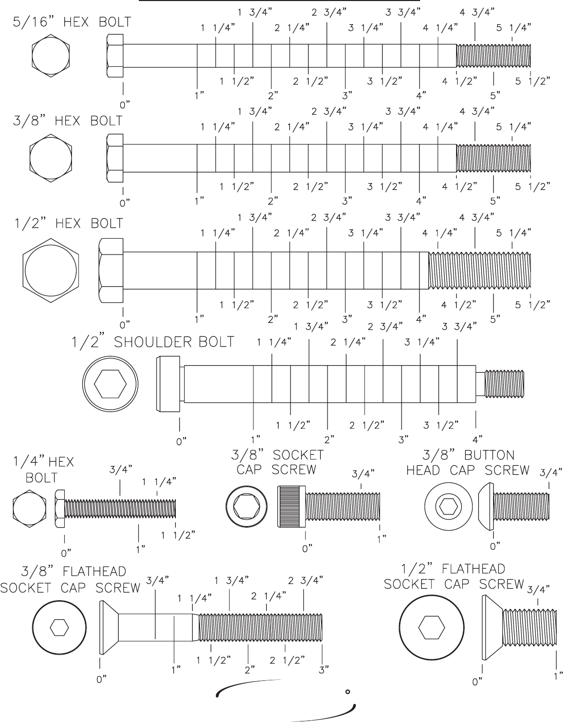
BOLT SIZING CHART
Page - 25 2408 Assembly
OWNERS
MANUAL
FITNESS SYSTEMS
R
HOIST
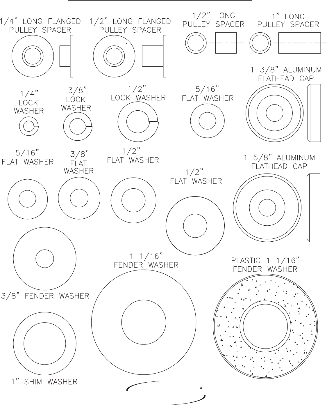
WASHER SIZING CHART
SMALL, SAE, 26mm
LARGE, USS, 34mm
LARGE, USS, 25mm
Page - 262408 Assembly
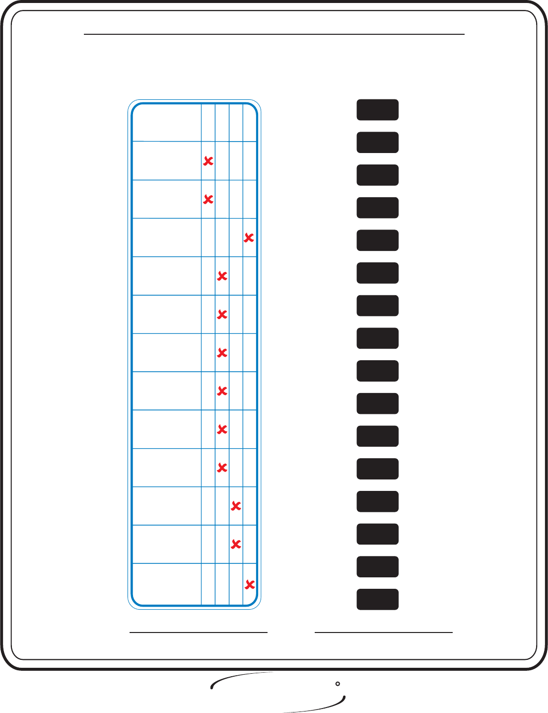
WEIGHT RATIOS
OWNERS
MANUAL
The above chart shows the actual weight you are lifting when the ratios
are applied. To find the actual weight you are lifting you would come down
from the ratio being used and across from the number of the weight plate you
have pinned.
FITNESS SYSTEMS
R
HOIST
50%
50%
18
218
328
438
548
658
768
878
988
10 98
11 108
12 118
11 128

FITNESS SYSTEMS
R
HOIST
Page - 27 2408 Assembly
OWNERS
MANUAL

2408 Assembly Page - 28
FITNESS SYSTEMS
R
HOIST
OWNERS
MANUAL
Hoist equipment is designed to maximize your time spent
working out. Having an exercise routine planned out in
advance will allow you to get the most benefit out of the time
spent exercising, and will also enable you to work all the major
muscle groups.
Warm up properly before engaging in weight resistance
training. Stretching, yoga, jogging, calisthenics or other
cardiovascular exercise can help prepare your body for the
heavier workload of lifting weights.
Learn how to perform the exercise correctly before using
heavy weight. Correct form is important to avoid injury and to
ensure that you work the proper muscle groups.
Know your limitations. If you are new to weight training
or are embarking on an exercise regimen after a long layoff,
start slowly and build foundational strength over a longer
period of time.
Pay attention to your breathing. Exhale when you exert
is a general rule of thumb. Never hold your breath.
Always consult your physician before starting any
exercise program.
WEIGHT TRAINING TIPS

Page - 29 2408 Assembly
FITNESS SYSTEMS
R
HOIST
OWNERS
MANUAL

FITNESS SYSTEMS
R
HOIST
2408 Assembly Page - 30
OWNERS
MANUAL
Weight Training Exercise Log
SR W
=Sets =Repetition per set =Weight used
SS
Exercise
Totals
SSSSSSSSSS
RRRRRRRRRRRR
WWWWWWWWWWWW
Date

OWNERS
MANUAL
FITNESS SYSTEMS
R
HOIST
2408 AssemblyPage - 31
OWNERS
MANUAL
FITNESS SYSTEMS
R
HOIST
2408 Assembly Page -32
DECAL PLACEMENTS
1 - 021-0004026
2 - 021-0003008
3 - 021-0004029
4 - 021-0004020
5 - 021-0003011
6 - 021-0003006
7 - 021-0012004
8 - 021-0013071
9 - 021-0003090
Decal Descriptions
1
2
9
1
5
6
8
3
4
Page - 332408 Assembly
FITNESS SYSTEMS
R
HOIST
OWNERS
MANUAL
DECAL REFERENCE
This decal has been attached to this piece of equipment to
provide information regarding operation, safety and
maintenance. Before use, take the time to read these decals.
021-0003008
MAINTENANCE
ROUTINE
Daily
Weekly
Yearly
Months
6
Inspect;
Links, Pull Pins,
Snap Locks, Swivels,
Weight Stack Pins
Clean;
Upholstery
Lubricate;
Guide Rods with
Waylube Oil only
Inspect;
Accessory Bars
and Handles
Inspect;
All Decals
Inspect;
All Nuts and Bolts,
Tighten if Needed
Inspect;
Anti- Skid Surfaces
Inspect;
Cables or
Belts Tension
Lubricate;
Seat Sleeves,
Turcite Bushings,
Linear Bearings
Clean and Wax;
All Glossy Finishes
Repack with Grease;
Linear Bearings
Replace;
Cables or Belts
Connecting Parts
1
2
3
4
5
6
7
8
9
10
11
12
13
14
15
16
021-0003011
FITNESS SYSTEMS
R
HOIST
2408 Assembly Page - 34
OWNERS
MANUAL
CL
CL
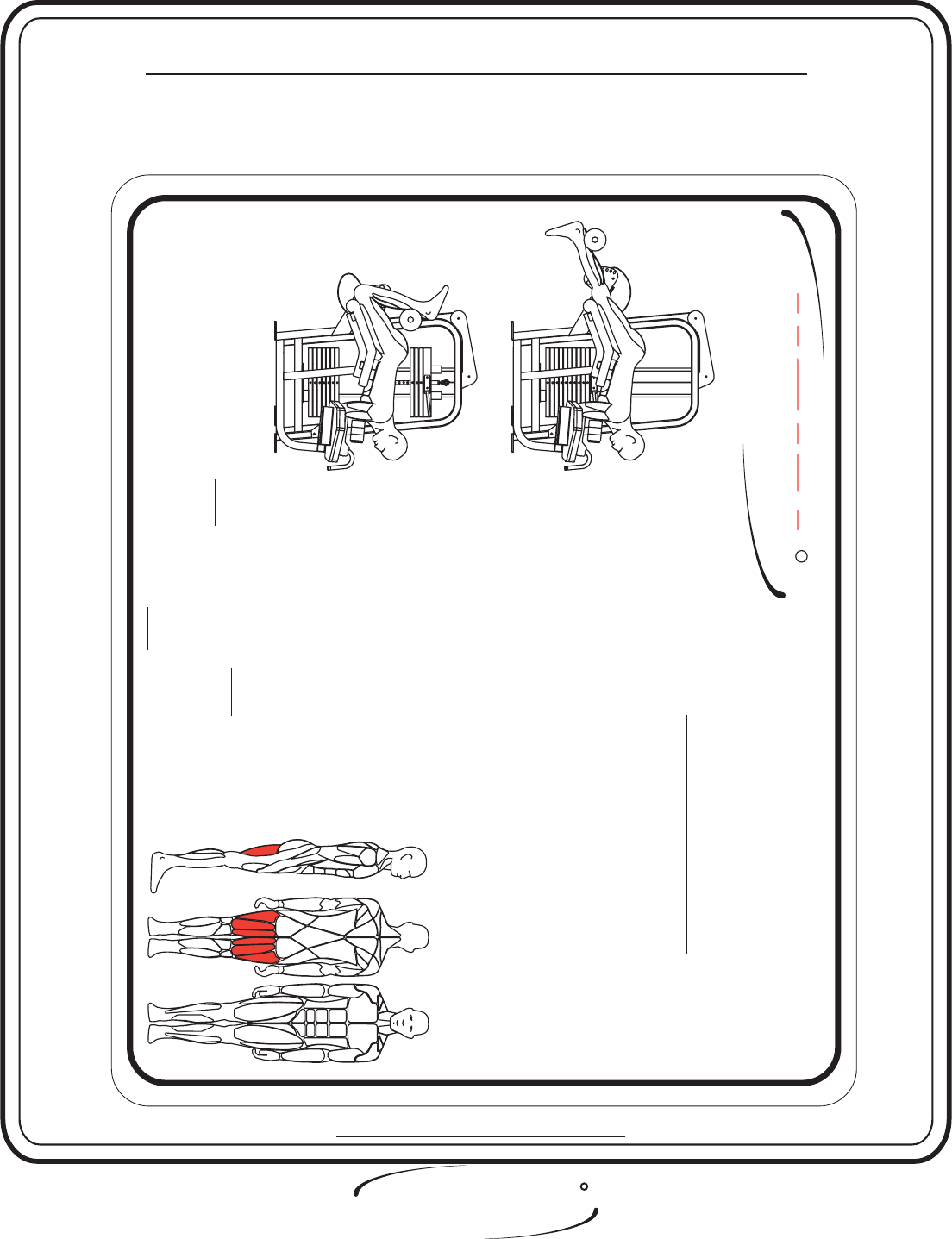
Start / End Position
Midpoint Position
PRIMARY:
Hamstrings
MUSCLES TRAINED
Lie face down on torso pads and select desired
exercise weight.
Adjust movement arm to desired beginning position.
(Legs straight but not hyper-extended recommended).
Exercise Instructions
PRONE
1
2
3
â
â
â
Read and understand all instructions before using this equipment.
Inspect equipment for loose, worn or frayed parts. If in doubt about a certain part use this machine.
Keep hands and feet away from moving parts. attempt to free any jammed part by yourself..
DO NOT
DO NOT
â
â
â
â
Always consult a physician before starting any exercise program.
Stop your workout immediately if you feel faint or dizzy.
Warm up before and cool down after engaging in weight resistance training.
Take your time and don't rush the exercise. Practice proper breathing, hold your breath.NEVER
2408
HOIST
FITNESS SYSTEMS
R
LEG CURL
Position knees just off thigh pad edge with lower legs
under roller pad. Curl legs upward to full contraction
with a smooth controlled movement. Return back to
starting position and perform desired number of
repetitions.
DECAL REFERENCE
This decal have been attached to this piece of equipment to
provide information regarding operation, safety and
maintenance. Before use, take the time to read these decals.
021-0013071
OWNERS
MANUAL
Page - 35 2408 Assembly
FITNESS SYSTEMS
R
HOIST
DECAL REFERENCE
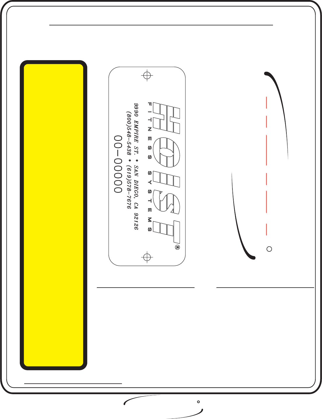
SERIAL # DECAL: Always refer to the
number shown on your piece of equipment
when talking to customer service or ordering
parts.
WARNING:
TO PREVENT
THE POSSIBILITY OF SERIOUS
INJURY, KEEP CLEAR OF ALL
MOVING PARTS.
There is a risk assumed by
individuals who use this type of
equipment. To minimize this
risk, always follow these
simple rules.
1. READ AND UNDERSTAND ALL ENCLOSED
INSTRUCTIONS
2. INSPECT EQUIPMENT DAILY
DO
NOT
3. DO NOT ATTEMPT
before using this equipment.
for loose, worn
or frayed parts. Replace all parts at the first
signs of wear. If in doubt about a certain part,
use the machine until the part is replaced.
Failure to replace worn parts may result in injury.
to free any jammed part by
yourself. Obtain assistance as the part may free
itself suddenly causing possible injury.
4. BE CERTAIN
DO NOT BE CARELESS.
5.
6.
CHILDREN SHOULD NOT BE
ALLOWED TO USE THIS EQUIPMENT.
7.
to keep your head, hands and
limbs clear of moving parts. Be alert to the
possibility of injury.
If you feel faint or dizzy, stop exercising at
once.
Teenagers should not use this machine without
adult supervision.
If you have any questions on the proper use
and maintenance of the machine, do not hesitate
R
HOIST
021-0004029
021-0003006
021-0012004
This decal has been attached to this piece of equipment to
provide information regarding operation, safety and
maintenance. Before use, take the time to read these decals.
Page - 362408 Assembly
FITNESS SYSTEMS
R
HOIST
OWNERS
MANUAL
R
HOIST
DECAL REFERENCE
This decal has been attached to this piece of equipment to
provide information regarding operation, safety and
maintenance. Before use, take the time to read these decals.
021-0003090
5
6
7
3
2
1
4
021-0004026
PATENT
PENDING
021-0004020

OWNERS
MANUAL
Page - 372408 Assembly
FITNESS SYSTEMS
R
HOIST
HOIST FITNESS SYSTEMS
GENERAL MAINTENANCE INFORMATION
Links, Pull-Pins, Snap Locks, Swivels, Weight Stack Pins:
Upholstery:
Guide Rods:
Decals:
Nuts and Bolts:
Belts and Cables:
F
F
F
F
F
F
F
F
F
F
F
F
F
F
F
Check all pieces for signs of visible wear or damage.
Check springs in snap hooks and pull-pins for proper tension and alignment.
If the spring sticks or has lost its rigidity, replace it immediately.
To ensure prolonged upholstery life and proper hygiene, all upholstered pads should be wiped down with a damp
cloth after every workout.
Periodically take the time to use a mild soap or an approved vinyl upholstery cleaner to deter the onset of cracking or
drying. Avoid using any abrasive cleaners or cleaners not intended for use on vinyl.
Replace ripped or worn upholstery immediately.
Keep sharp or pointed objects clear of all upholstery.
Wipe clean with a clean, dust free rag.
If lubrication is required, lube with or damage to the Top Weight Bearing may occur.
DO NOT repeatedly clean the shafting with alcohol or any other stripping cleanser! The Top Weight Bearing
transfers a gliding material to the guide rods. Cleaning other than wiping with a clean, dust free rag will remove the
previously transferred material and increase the wear to the Bearing Liner.
Inspect and familiarize yourself with any safety warnings or other user information posted on each decal.
nspect all nuts and bolts for any loosening and tighten if needed.
Go through a re-tightening sequence periodically to ensure that all hardware is tensioned properly.
Hoist uses only high quality belts, and mil-spec cables.
Visually inspect the belts and cables for fraying, cracking, peeling or discoloration.
While the machine is not in use, carefully run your fingers along the belt or cable to feel for thinning or bulging
areas.
Replace belts and cables immediately at the first signs of damage or wear. Do not use equipment until belts or cables
has been replaced.
I
Waylube Oil ONLY
F
F

Page - 382408 Assembly
FITNESS SYSTEMS
R
HOIST
OWNERS
MANUAL
Continued: GENERAL MAINTENANCE INFORMATION
Belt and Cable Tension:
Seat Sleeves & Oilites:
Linear Bearings:
FReferring to the Assembly/Owners Manual, when belts or cables are used check all bolts and attachments to be sure
they are properly attached.
Check slack in belts or cables and readjust tension if needed.
Wipe down adjusting tubes with a dust free rag before applying lubricant.
Lubricate seat sleeves and oilites with a Silicon or Teflon based lubricant spray.
Referring to the Assembly/ Owners manual carefully dis-assemble the bearing from its housing and place a finger
full of light grease (lithium, super lube, etc.) into the inside of the bearing. Using your finger, press the grease into the
ball-bearings and their tracks. Repeat until the ball-bearing tracks are full of grease. Insert the shaft back into the
bearing and wipe off excess grease.
F
F
F
F
F
Anti-Skid Surfaces:
These surfaces are designed to supply secure footing and need to be replaced if they appear worn or become slippery.
PLEASE KEEP THIS FOR YOUR RECORDS.

Page - 392408 Assembly
FITNESS SYSTEMS
R
HOIST
OWNERS
MANUAL

Page - 402408 Assembly
FITNESS SYSTEMS
R
HOIST
OWNERS
MANUAL
Hoist Fitness Systems
LIMITED LIFETIME WARRANTY
Hoist Fitness Systems warrants this product to the to be free from defects in workmanship
and/or materials under normal use or service. If at any time a component part is defective, Hoist Fitness
Systems shall repair or replace it (at Hoist Fitness Systems option) within a reasonable period of time.
This warranty does not cover costs of removal, transportation or reinstallation. This warranty shall not apply if
the defect was caused by misuse, neglect or normal wear and tear.
Starting from the original date of purchase, normal wear and tear shall be considered as the following: All
malfunctions of upholstery and paint that occur after 90 days; all malfunctions of electronic components, belts or
cables that occur after one year; all malfunctions of pulleys, bearings or bushings that occur after five years. The
frame and all welded components are warranted for the life of the product.
Hoist Fitness Systems sole responsibility shall be to repair or replace the component within the terms stated
above. Hoist Fitness Systems shall not be liable for any loss or damage of any kind including any incidental or
consequential damages resulting, directly or indirectly from any warranty expressed or implied or any other
failure of this product.
WHAT IS NOT COVERED BY THIS WARRANTY
Hoist’s sole obligation under this warranty is limited to either repair or replacement of parts, subject to the
additions below. This warranty neither assumes nor authorizes any person to assume obligations other than
expressly covered by this warranty.
NO CONSEQUENTIAL DAMAGES. Hoist is not responsible for economic loss; profit loss; or special, indirect, or
consequential damages.
WARRANTY IS NOT TRANSFERABLE. This warranty is not assignable and applies only in favor of the original
purchaser/user to whom delivered. Any such assignment or transfer shall void the warranties herein made and
shall void all warranties, express, implied or statutory, except the one (1) and (5) year warranty described above.
These warranties are exclusive and in lieu of all other warranties, including implied warranty and merchantability
or fitness for a particular purpose. There are no warranties which extend beyond the description on the face
hereof.
ALTERATION, NEGLECT, ABUSE, MISUSE, NORMAL WEAR & TEAR, ACCIDENT, DAMAGE DURING
TRANSIT OR INSTALLATION, FIRE, FLOOD, ACTS OF GOD. Hoist is not responsible for the repair or
replacement of any parts that Hoist determines have been subjected after the date of manufacture to alteration,
neglect, abuse, misuse, normal wear & tear, accident, damage during transit or installation, fire, flood, or an ACT
OF GOD.
TRANSPORTATION COSTS. Hoist will accept parts covered under this warranty freight collect, provided that
shipment has received prior approval. Hoist is not responsible for any other transportation costs, but will ship
freight collect parts either repaired or replaced under these warranties.
WARRANTY CLAIMS. All claims should include: model number, the serial number, proof of purchase, date of
installation, and all pertinent information supporting the existence of the alleged defect.
original purchaser
Hoist Fitness Systems
9990 Empire St., #130
San Diego, Calif., 92126
(800)548-5438
Web Site - www.hoistfitness.com
PLEASE KEEP THIS FOR YOUR RECORDS.
