Hologic PCB00116 RFID Tag User Manual MAN 01964
Hologic Inc RFID Tag MAN 01964
UserManual.wiki
>
Hologic
>
PCB00116 User Manual
Users Manual
Navigation menu
Upload a User Manual
Namespaces
Wiki Guide
HTML
PDF
Info
Views
User Manual
Discussion / Help
Navigation


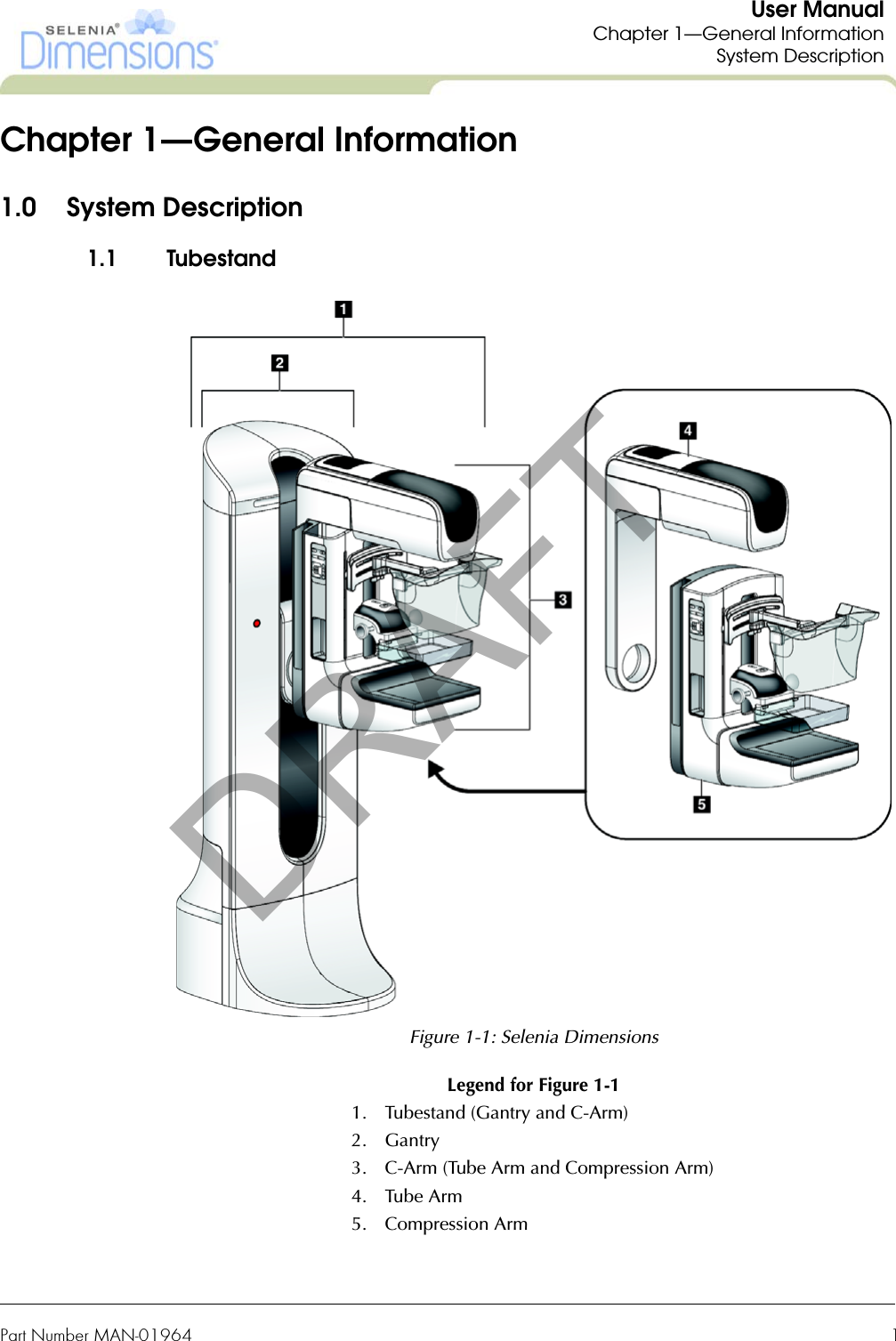
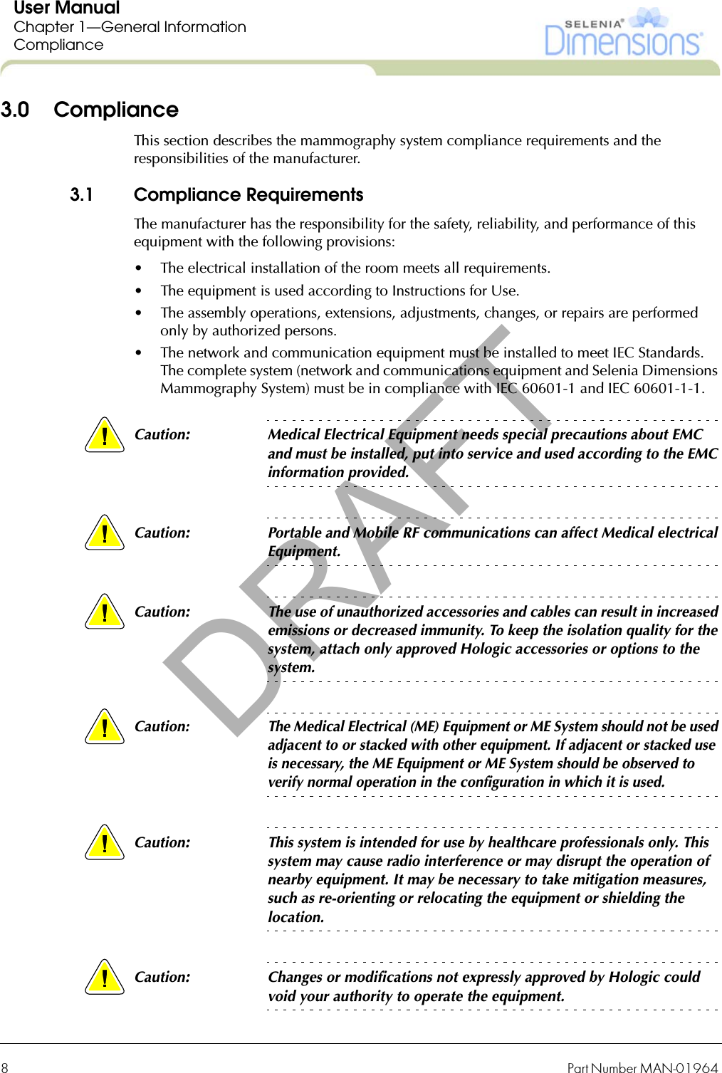
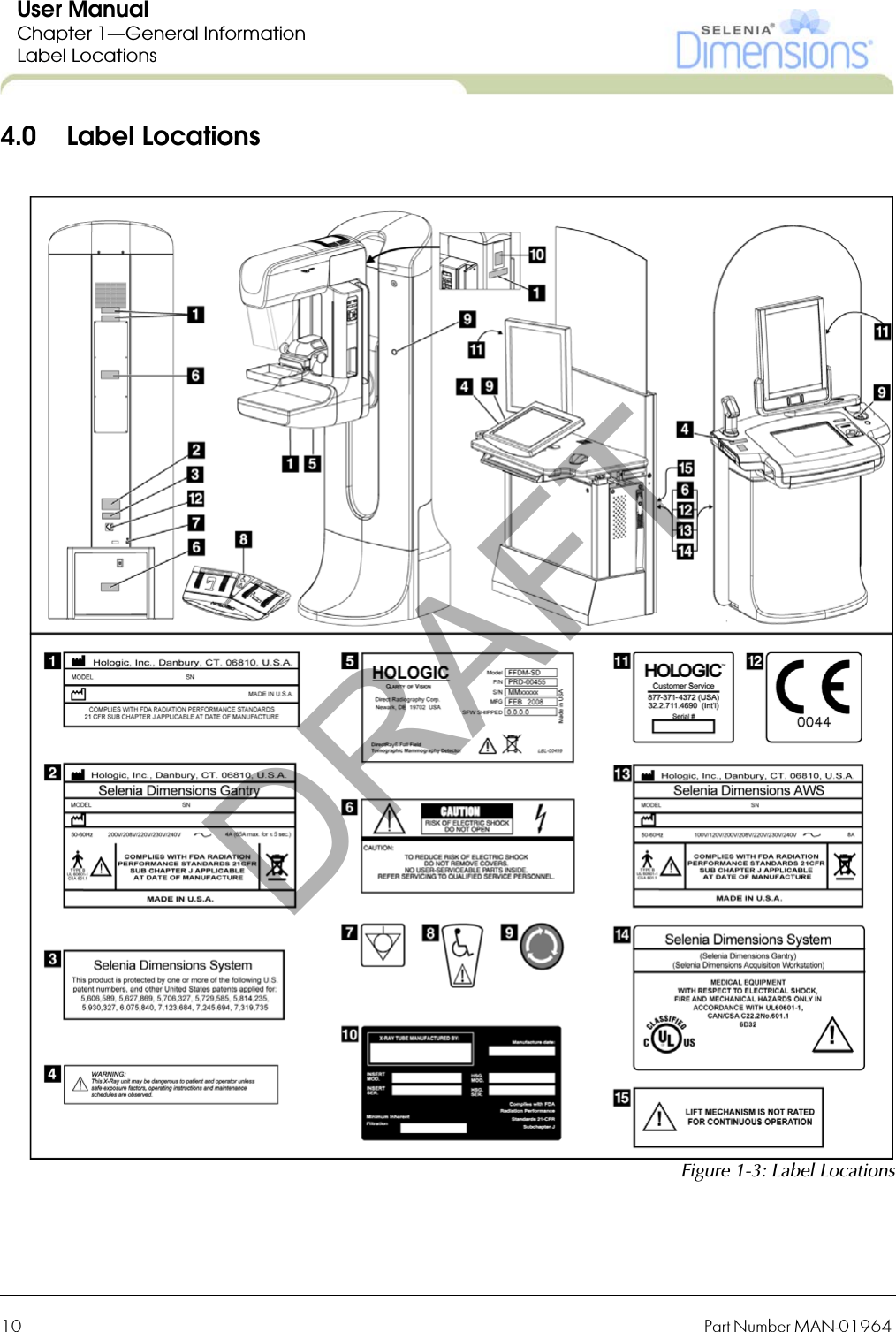
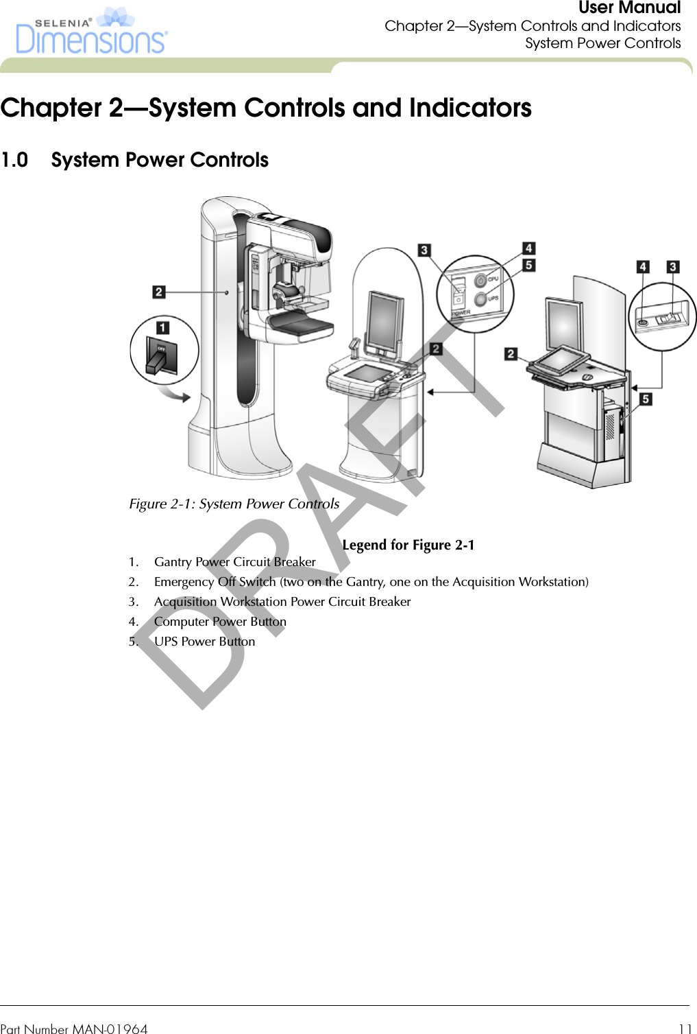
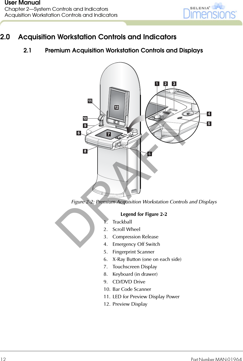
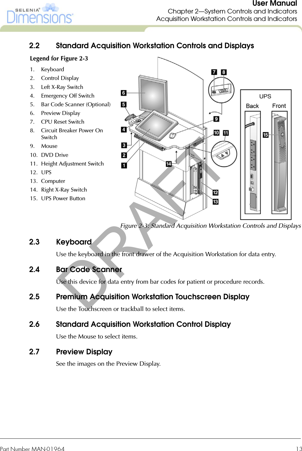
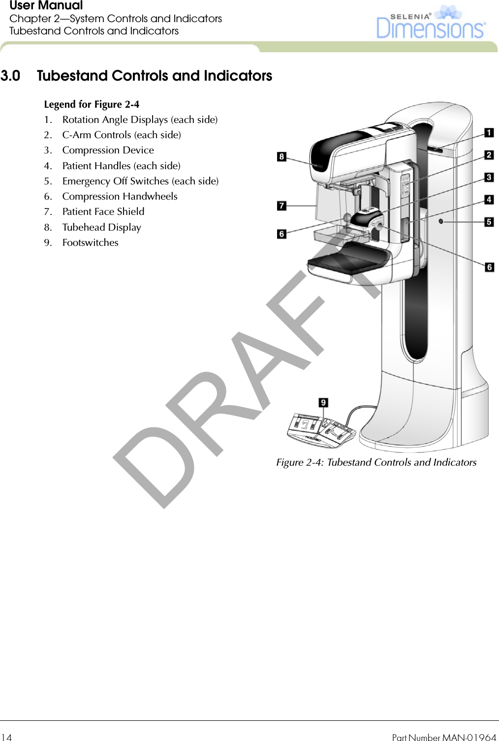
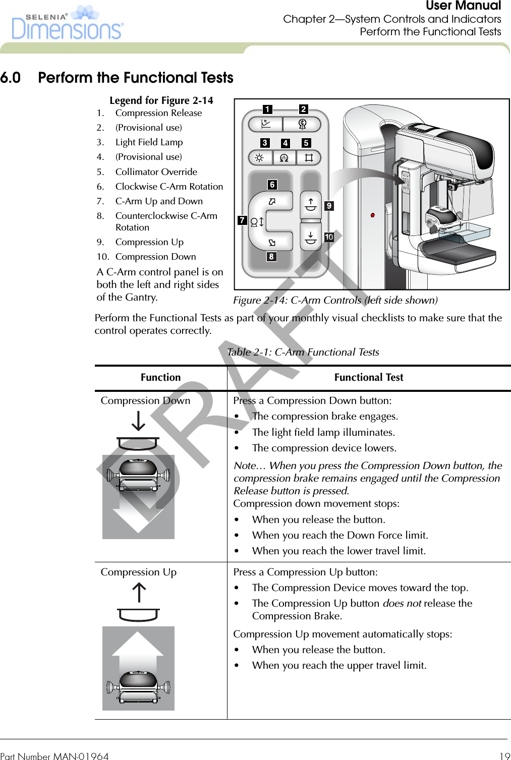
![Part Number MAN-01964 9User ManualChapter 1—General InformationComplianceCaution: This equipment has been tested and found to comply with the limits for a Class A digital device, pursuant to part 15 of the FCC Rules. These limits are designed to provide reasonable protection against harmful interference when the equipment is operated in a commercial environment. This equipment generates, uses, and can radiate radio frequency energy and, if not installed and used in accordance with the instruction manual, may cause harmful interference to radio communications. Operation of this equipment in a residential area is likely to cause harmful interference in which case the user will be required to correct the interference at his own expense.3.2 Compliance StatementsThe manufacturer states this device is made to meet the following requirements:• CAN/CSA ISO 13485:2003• CAN/CSA: Medical Electrical Equipment Part 1: C22.2 No. 601.1–M90 (R2005)—General Requirements for Safety• EN 60601-1:1990 +A1+A11+A12+A2+A13 Medical Electrical Equipment—General Requirements for Basic Safety and Essential Performance• ETSI EN 300 330-1 V1.7.1(2010-02)—Electromagnetic compatibility and Radio spectrum Matters (ERM); Short Range Devices (SRD); Radio equipment in the frequency range 9 kHz to 25 MHz and inductive loop systems in the frequency range 9 kHz to 30 MHz• ETSI EN 301 489-1: V1.8.1 (2008-04)—Electromagnetic compatibility and Radio spectrum Matters (ERM); ElectroMagnetic Compatibility (EMC) standard for radio equipment and services• FCC, 47 CFR [Part 15, Subpart C, Section 15.225]• FDA, 21 CFR [Parts 820, 900 and 1020]• IEC 60601-1:1988 +A1+A2:1995Medical Electrical Equipment—General Requirements for Safety • IEC 60601-1-1:2000 Medical Electrical Equipment—Collateral Standard: Safety Requirements for Medical Electrical Systems• IEC 60601-1-2:2007 Medical Electrical Equipment—Collateral Standard: Electromagnetic Compatibility for Medical Electric Systems • IEC 60601-1-3:1994 Medical Electrical Equipment—Collateral Standard: Requirements for Radiation Protection in Diagnostic X-ray Equipment• IEC 60601-1-4:1996 +A1:1999 Medical Electrical Equipment—Collateral Standard: Programmable Electrical Medical Systems• IEC 60601-2-28:1993 Medical Electrical Equipment—Particular Requirements for the Safety of X-ray Source Assemblies and X-ray Tube Assemblies for Medical Diagnosis• IEC 60601-2-32:1994 Medical Electrical Equipment—Particular Requirements for the Safety of Associated Equipment of X-ray Equipment • IEC 60601-2-45:2001 Medical Electrical Equipment—Particular Requirements for the Safety of Mammographic X-ray Equipment and Mammographic Stereotactic Devices• RSS-210: Issue 7, 2007• UL 60601-1 1st Edition: Medical Electrical Equipment, Part 1—General Requirements for SafetyDRAFT](https://usermanual.wiki/Hologic/PCB00116/User-Guide-1385195-Page-29.png)