Users Manual
DRAFT
DRAFT
DRAFT
DRAFT

Part Number MAN-01964 v
User Manual
Table of Contents
Table of Contents
List of Figures xi
List of Tables xiii
Preface xv
1.0 Intended Use Statements ...................................................................................................................... xv
1.1 Intended Use .................................................................................................................................. xv
1.2 Intended Use (Tomosynthesis Option) ............................................................................................ xv
2.0 System Capabilities ............................................................................................................................... xv
3.0 Users .................................................................................................................................................... xv
4.0 Skills Needed for System Use .............................................................................................................. xvi
5.0 Training Requirements ......................................................................................................................... xvi
6.0 Quality Control Requirements ............................................................................................................. xvi
7.0 Product Complaints ............................................................................................................................. xvi
8.0 Hologic Cybersecurity Statement ......................................................................................................... xvi
9.0 Warnings, Cautions, and Notes .......................................................................................................... xvii
10.0 Terms and Definitions ..................................................................................................................... xviii
11.0 International Symbols ........................................................................................................................ xix
12.0 Document Standards ......................................................................................................................... xix
Chapter 1—General Information 1
1.0 System Description .................................................................................................................................1
1.1 Tubestand ........................................................................................................................................1
1.2 Acquisition Workstation ...................................................................................................................2
2.0 Safety Information ..................................................................................................................................3
2.1 General Safety ..................................................................................................................................3
2.2 Patient Safety ...................................................................................................................................4
2.3 Radiation Safety ...............................................................................................................................5
2.4 Data Loss .........................................................................................................................................6
2.5 Equipment Damage ..........................................................................................................................6
2.6 Emergency Off Switches ...................................................................................................................7
2.7 Interlocks .........................................................................................................................................7
3.0 Compliance ............................................................................................................................................8
3.1 Compliance Requirements ...............................................................................................................8
3.2 Compliance Statements ....................................................................................................................9
4.0 Label Locations ....................................................................................................................................10
Chapter 2—System Controls and Indicators 11
1.0 System Power Controls .........................................................................................................................11
2.0 Acquisition Workstation Controls and Indicators ..................................................................................12
2.1 Premium Acquisition Workstation Controls and Displays ...............................................................12
2.2 Standard Acquisition Workstation Controls and Displays ...............................................................13
2.3 Keyboard .......................................................................................................................................13
2.4 Bar Code Scanner ..........................................................................................................................13
2.5 Premium Acquisition Workstation Touchscreen Display ................................................................13
2.6 Standard Acquisition Workstation Control Display .........................................................................13
2.7 Preview Display .............................................................................................................................13
DRAFT

vi Part Number MAN-01964
User Manual
Table of Contents
3.0 Tubestand Controls and Indicators ....................................................................................................... 14
3.1 C-Arm Controls ............................................................................................................................. 15
3.2 Compression Device Controls and Displays .................................................................................. 15
3.3 Tubehead Display ......................................................................................................................... 16
3.4 Dual Function Footswitches .......................................................................................................... 16
4.0 How to Turn On the Selenia Dimensions ............................................................................................. 17
4.1 Preparation .................................................................................................................................... 17
4.2 Startup ........................................................................................................................................... 17
4.3 Log In ............................................................................................................................................ 18
5.0 How to Change the Language .............................................................................................................. 18
6.0 Perform the Functional Tests ................................................................................................................ 19
7.0 How to Turn Off the System ................................................................................................................. 25
8.0 How to Remove All Power from the Acquisition Workstation .............................................................. 25
Chapter 3—The User Interface 27
1.0 Select the Function to Perform ............................................................................................................. 27
2.0 How to Perform the Quality Control Tasks ........................................................................................... 28
3.0 The Select Patient Screen ..................................................................................................................... 29
3.1 How to Open a Procedure ............................................................................................................. 29
3.2 How to Add a New Patient ............................................................................................................ 30
3.3 How to Edit the Patient Information ............................................................................................... 30
3.4 How to Delete a Patient ................................................................................................................ 30
3.5 The Patient Filter Screen ................................................................................................................ 31
3.6 How to Refresh the Worklist .......................................................................................................... 32
3.7 How to Query the Worklist ........................................................................................................... 33
3.8 About the Admin Button ................................................................................................................ 33
3.9 How to Log Out ............................................................................................................................ 33
4.0 The Procedure Screen .......................................................................................................................... 34
4.1 How to Set the Exposure Parameters .............................................................................................. 34
4.2 How to Use the Implant Present Button ......................................................................................... 35
4.3 How to Acquire an Image .............................................................................................................. 35
4.4 How to Add or Remove a View ..................................................................................................... 36
4.5 How to Add a Procedure ............................................................................................................... 37
4.6 How to Edit a View ....................................................................................................................... 37
4.7 How to Close a Procedure ............................................................................................................. 38
5.0 How to Access Image Review Features ................................................................................................ 38
6.0 How to Use the Output Sets ................................................................................................................. 39
6.1 How to Select an Output Set ......................................................................................................... 39
6.2 How to Add or Edit an Output Set ................................................................................................. 39
7.0 How to Use the On-Demand Outputs .................................................................................................. 39
7.1 How to Archive ............................................................................................................................. 39
7.2 How to Print .................................................................................................................................. 40
7.3 How to Export ............................................................................................................................... 41
8.0 How to Use the Paddle Shift Feature .................................................................................................... 41
9.0 About the Taskbar ................................................................................................................................ 42
DRAFT

Part Number MAN-01964 vii
User Manual
Table of Contents
Chapter 4—The Images 43
1.0 Introduction ..........................................................................................................................................43
1.1 Conventional Sequence of Events ...................................................................................................43
1.2 Tomosynthesis Sequence of Events (Tomosynthesis option) ............................................................43
2.0 How to Review the Images ...................................................................................................................44
2.1 The Image Review Tools Tab .........................................................................................................45
2.2 Other Image Review Tools .............................................................................................................46
2.3 How to Correct and Reprocess Implant Images ..............................................................................47
3.0 Send the Images to the Output Devices ................................................................................................47
Chapter 5—How to Use the Accessories 49
1.0 Introduction ..........................................................................................................................................49
2.0 How to Install Accessories on the C-Arm ..............................................................................................49
3.0 The Patient Face Shields .......................................................................................................................50
3.1 How to Install or Remove the Retractable Face Shield ....................................................................50
3.2 How to Use the Retractable Face Shield .........................................................................................51
3.3 How to Install or Remove the Conventional Face Shield ................................................................52
4.0 Compression Paddles ...........................................................................................................................53
4.1 Routine Screening Paddles .............................................................................................................53
4.2 Contact and Spot Compression Paddles .........................................................................................53
4.3 Localization Paddles ......................................................................................................................54
4.4 Magnification Paddles ....................................................................................................................54
4.5 How to Install or Remove a Compression Paddle ...........................................................................55
4.6 Maintenance and Cleaning ............................................................................................................55
4.7 Paddle Shift ....................................................................................................................................55
4.8 FAST Compression Mode ...............................................................................................................56
5.0 Magnification Stand ..............................................................................................................................57
5.1 How to Install and Remove the Magnification Stand ......................................................................57
6.0 Crosshair Devices .................................................................................................................................58
6.1 How to Install and Remove the Localization Crosshair Device .......................................................58
6.2 How to Use the Localization Crosshair Device ..............................................................................58
6.3 How to Install and Remove the Magnification Crosshair Device ....................................................59
6.4 How to Align the Crosshair Device ................................................................................................59
Chapter 6—Clinical Procedures 61
1.0 Standard Workflow ...............................................................................................................................61
1.1 Preparation ....................................................................................................................................61
1.2 At the Gantry .................................................................................................................................61
1.3 At the Acquisition Workstation .......................................................................................................61
2.0 Screening Procedure Example ..............................................................................................................62
2.1 How to Position the Patient ............................................................................................................62
2.2 Set the Exposure Techniques ..........................................................................................................62
2.3 How to Acquire the Exposure .........................................................................................................63
2.4 How to Automatically Store the Image ...........................................................................................63
2.5 How to Accept a Rejected Image ...................................................................................................63
2.6 How to Accept or Reject a Pended Image ......................................................................................63
DRAFT

viii Part Number MAN-01964
User Manual
Table of Contents
Chapter 7—Maintenance and Cleaning 65
1.0 General Information ............................................................................................................................. 65
1.1 For General Cleaning .................................................................................................................... 65
1.2 To prevent Possible Injury or Equipment Damage .......................................................................... 66
2.0 Acquisition Workstation ....................................................................................................................... 67
2.1 How to Clean the Preview Display ................................................................................................ 67
2.2 How to Clean the Touchscreen Display ......................................................................................... 67
2.3 How to Clean the Keyboard .......................................................................................................... 67
2.4 How to Clean the Fingerprint Scanner ........................................................................................... 67
3.0 Preventive Maintenance Schedule ....................................................................................................... 68
Chapter 8—System Administration Interface 69
1.0 How to Use the Admin Screen ............................................................................................................. 69
2.0 How to Use the System Tools .............................................................................................................. 72
2.1 The Radiologic Technologist Manager ........................................................................................... 72
Appendix A—Specifications 75
1.0 Product Measurements ......................................................................................................................... 75
1.1 Tubestand (Gantry with C-Arm) ..................................................................................................... 75
1.2 Premium Acquisition Workstation ................................................................................................. 76
1.3 Standard Acquisition Workstation .................................................................................................. 77
2.0 Operation and Storage Environment .................................................................................................... 78
2.1 General Conditions for Operation ................................................................................................. 78
2.2 Storage Environment ...................................................................................................................... 78
3.0 Acquisition Workstation Technical Information ................................................................................... 78
4.0 Electrical Input ..................................................................................................................................... 79
4.1 Tubestand ...................................................................................................................................... 79
4.2 Acquisition Workstation ................................................................................................................ 79
5.0 Tubestand Technical Information ......................................................................................................... 79
5.1 C-Arm ........................................................................................................................................... 79
5.2 Compression ................................................................................................................................. 80
5.3 X-Ray Tube .................................................................................................................................... 80
5.4 X-Ray Beam Filtration and Output ................................................................................................. 81
5.5 X-Ray Collimation ......................................................................................................................... 82
5.6 Light Field Indication ..................................................................................................................... 82
5.7 X-Ray Generator ............................................................................................................................ 82
6.0 Imaging System Technical Information ................................................................................................. 82
6.1 Image Receptor ............................................................................................................................. 82
Appendix B—The System Messages and Alert Messages 83
1.0 Error Recovery and Troubleshooting .................................................................................................... 83
2.0 Types of Messages and Alert messages ................................................................................................. 83
2.1 Fault Levels ................................................................................................................................... 83
2.2 System Messages ........................................................................................................................... 84
DRAFT

Part Number MAN-01964 ix
User Manual
Table of Contents
Appendix C—Dimensions Mobile 85
1.0 General Information .............................................................................................................................85
2.0 Conditions for Safety and Other Precautions .........................................................................................85
3.0 Mobile Specifications ...........................................................................................................................86
3.1 Shock and Vibration Limits ............................................................................................................86
3.2 Coach Environment ........................................................................................................................86
4.0 Electrical Input .....................................................................................................................................86
4.1 Gantry ............................................................................................................................................86
4.2 Acquisition Workstation .................................................................................................................86
5.0 Prepare the System for Travel ...............................................................................................................87
6.0 Prepare the System for Use ...................................................................................................................87
7.0 Test the System after Travel ..................................................................................................................88
7.1 Selenia Dimensions Controls and Functional Tests .........................................................................88
8.0 Quality Control Tests ............................................................................................................................88
List of Addenda 89
Index 91
DRAFT

xPart Number MAN-01964
User Manual
Table of Contents
DRAFT

Part Number MAN-01964 xi
User Manual
List of Figures
List of Figures
Figure 1-1: Selenia Dimensions .................................................................................................................... 1
Figure 1-2: Acquisition Workstations ............................................................................................................ 2
Figure 1-3: Label Locations......................................................................................................................... 10
Figure 2-1: System Power Controls ............................................................................................................. 11
Figure 2-2: Premium Acquisition Workstation Controls and Displays ......................................................... 12
Figure 2-3: Standard Acquisition Workstation Controls and Displays.......................................................... 13
Figure 2-4: Tubestand Controls and Indicators............................................................................................ 14
Figure 2-5: C-Arm Controls......................................................................................................................... 15
Figure 2-6: Compression Device................................................................................................................. 15
Figure 2-7: Compression Display................................................................................................................ 15
Figure 2-8: Tubehead Display..................................................................................................................... 16
Figure 2-9: Dual Function Footswitches...................................................................................................... 16
Figure 2-10: Premium Acquisition Workstation Power Buttons ................................................................... 17
Figure 2-11: Standard Acquisition Workstation Power Buttons ................................................................... 17
Figure 2-12: The Startup Screen.................................................................................................................. 17
Figure 2-13: How to Log In......................................................................................................................... 18
Figure 2-14: C-Arm Controls (left side shown) ............................................................................................ 19
Figure 3-1: An Example Select Function to Perform Screen......................................................................... 27
Figure 3-2: An Example Quality Control Screen.......................................................................................... 28
Figure 3-3: The Select Patient Screen.......................................................................................................... 29
Figure 3-4: How to Add a New Patient ....................................................................................................... 30
Figure 3-5: The Filter Tab in the Patient Filter Screen.................................................................................. 31
Figure 3-6: /The Generator Tab in an Example Procedure Screen ............................................................... 34
Figure 3-7: The Add View Screen ............................................................................................................... 36
Figure 3-8: The Add Procedure Dialog Box ................................................................................................ 37
Figure 3-9: The Edit View Screen................................................................................................................ 37
Figure 3-10: The Print Screen ..................................................................................................................... 40
Figure 3-11: Paddle Shift Buttons................................................................................................................ 41
Figure 4-1: The Preview Screen .................................................................................................................. 43
Figure 4-2: The Tools Tab (Tomosynthesis option shown)........................................................................... 44
Figure 4-3: Marked Images in a Procedure (Tomosynthesis option shown).................................................. 44
Figure 4-4: Image Review Tools.................................................................................................................. 45
Figure 4-5: Icons Available on the Notices Tab........................................................................................... 46
Figure 4-6: Exposure Index ......................................................................................................................... 46
Figure 4-7: Exposure Index ......................................................................................................................... 47
Figure 5-1: C-Arm Accessories.................................................................................................................... 49
Figure 5-2: How to Align the Retractable Face Shield on the C-Arm ........................................................... 50
Figure 5-3: Installation................................................................................................................................ 51
Figure 5-4: Operation ................................................................................................................................. 51
Figure 5-5: How to Install the Conventional Face Shield............................................................................. 52
Figure 5-6: How to Install a Compression Paddle ....................................................................................... 55
Figure 5-7: How to Remove the Compression Paddle ................................................................................. 55
Figure 5-8: The FAST Compression Mode Slide .......................................................................................... 56
Figure 5-9: Installation of the Magnification Stand ...................................................................................... 57
Figure 5-10: How to Attach the Localization Crosshair Device ................................................................... 58
Figure 5-11: How to Install and Remove the Magnification Crosshair Device ............................................. 59
Figure 6-1: Screening Example, Conventional Procedure............................................................................ 62
Figure 8-1: The Admin Screen .................................................................................................................... 70
DRAFT

xii Part Number MAN-01964
User Manual
List of Figures
Figure A-1: Tubestand Dimensions ............................................................................................................ 75
Figure A-2: Premium Acquisition Workstation Dimensions ........................................................................ 76
Figure A-3: Standard Acquisition Workstation Dimensions......................................................................... 77
Figure C-1: Keyboard Tray Lock Knob........................................................................................................ 87
Figure C-2: How to Unlock the Keyboard .................................................................................................. 87
DRAFT

Part Number MAN-01964 xiii
User Manual
List of Tables
List of Tables
Table 2-1: C-Arm Functional Tests...............................................................................................................19
Table 3-1: The Filter Tab Options (Require Access Privileges)......................................................................32
Table 3-2: Taskbar Menus ...........................................................................................................................42
Table 7-1: User Preventive Maintenance .....................................................................................................68
Table 8-1: Admin Screen Functions .............................................................................................................71
Table 8-2: Radiologic Technologist Manager—Service Tools Functions.......................................................73
Table A-1: Maximum mA Setting as a Function of kV ..................................................................................81
Table B-1: System Messages ........................................................................................................................84
DRAFT

xiv Part Number MAN-01964
User Manual
List of Tables
DRAFT

Part Number MAN-01964 xv
User Manual
Preface
Intended Use Statements
Preface
1.0 Intended Use Statements
United States Federal Law restricts this device to use by, or on the order of, a physician.
1.1 Intended Use
The Selenia® Dimensions® Full Field Digital Mammography system generates digital
mammographic images that can be used for screening and diagnosis of breast cancer. The
Selenia Dimensions Full Field Digital Mammography system is intended for use in the same
clinical applications as traditional screen-film mammographic systems. Mammographic
images can be interpreted on either hard copy film or soft copy review workstations.
1.2 Intended Use (Tomosynthesis Option)
The Selenia® Dimensions® Full Field Digital Mammography system acquires the digital
mammography images which can be used for screening and diagnosis of breast cancer. The
Selenia Dimensions system is intended for the clinical methods used with conventional Full
Field Digital Mammography systems. The Selenia Dimensions system can acquire
conventional full field digital mammograms in two dimensions and tomosynthesis
mammograms in three dimensions. The screening examination has a conventional image
set, or a conventional image set and a tomosynthesis image set.
Note… In Canada, Tomosynthesis is not approved for screening, and must be
used in conjunction with conventional mammography (2D image set).
2.0 System Capabilities
The system provides the user interfaces for the performance of screening and diagnostic
mammograms:
• Conventional mammography with a digital image receptor equivalent in size to large
mammography film.
• Tomosynthesis scan with a digital image receptor equivalent in size to large
mammography film (Tomosynthesis option).
• Conventional digital mammogram and tomosynthesis scan during one compression
(Tomosynthesis option).
3.0 Users
• A Technologist to acquire and review images
• A Technologist to perform the Quality Assurance
• A system administrator to enable permissions
• A Medical Physicist to perform the Quality Control tests
• A Radiologist can use the system with a Technologist
• The service personnel to install the system, set the site system configurations and
calibrations, and find faults
DRAFT

xvi Part Number MAN-01964
User Manual
Preface
Skills Needed for System Use
4.0 Skills Needed for System Use
You must know how to do the following:
• Perform the trackball operations, like click, drag, and/or select
• Perform the touchscreen operations
• Select from menus
• Type information in text fields
• Select the options in the screens
• Select the entries from drop-down lists
• Use scroll bars
5.0 Training Requirements
Hologic™ does not accept the responsibility for injury or damage from incorrect system
operation.
Make sure that you receive training on the Selenia Dimensions before you use this system on
patients. Hologic training programs address MQSA training requirements for any
Technologist or Physician.
Refer to this manual for directions on how to use Selenia Dimensions.
6.0 Quality Control Requirements
The facilities in the United States must use the Quality Control Manual to create a Quality
Assurance and Quality Control program. The facility must create the program to meet the
requirements of the Mammography Quality Standards Act or to be accredited by ACR or
another accreditation body.
The facilities outside the United States can use the Quality Control Manual as a guide to
create a program to meet the local standards and regulations.
7.0 Product Complaints
Report any complaints or problem in the quality, reliability, safety, or performance of this
product to Hologic. If the device has caused or added to patient injury, immediately report
the incident to Hologic. (See the title page for contact information.)
8.0 Hologic Cybersecurity Statement
Hologic continuously tests the current state of computer and network security to examine
possible security problems. When necessary, Hologic provides the updates to the product.
For Cybersecurity Best Practices documents for Hologic products, refer to the Hologic
Internet site.
DRAFT
Part Number MAN-01964 xvii
User Manual
Preface
Warnings, Cautions, and Notes
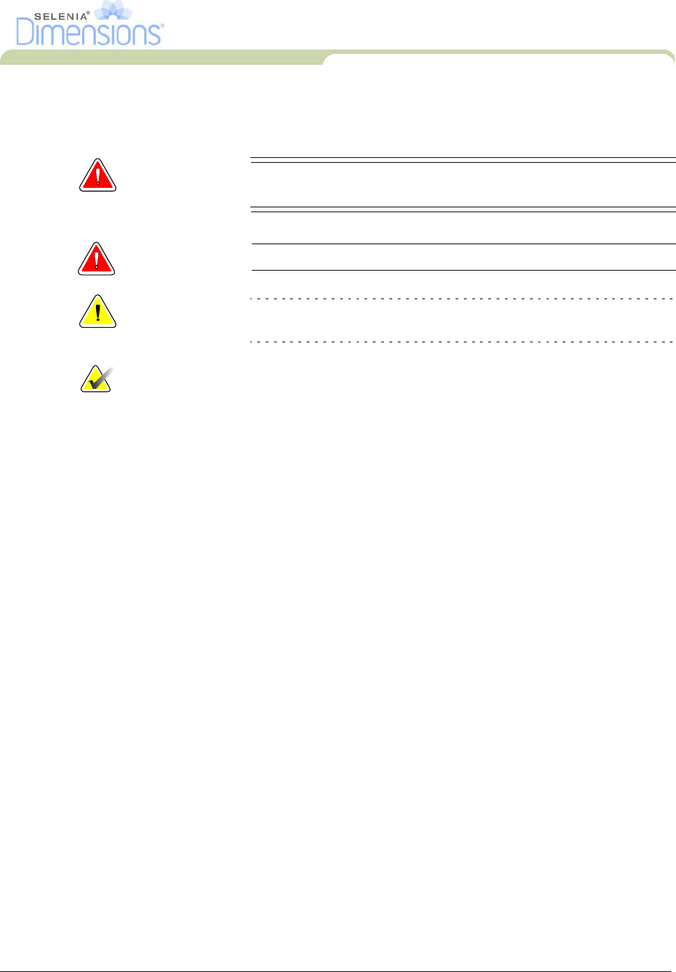
9.0 Warnings, Cautions, and Notes
Descriptions of Warnings, Cautions, and Notes used in this manual:
WARNING! The procedures that you must follow accurately to prevent
possible dangerous or fatal injury.
Warning:
The procedures that you must follow accurately to prevent injury.
Caution: The procedures that you must follow accurately to prevent the damage
to equipment, loss of data, or damage to files in software applications.
Note… Notes indicate additional information.
DRAFT

xviii Part Number MAN-01964
User Manual
Preface
Terms and Definitions
10.0 Terms and Definitions
ACR American College of Radiology
AEC Automatic Exposure Control
Annotations Graphic or text marks on an image to indicate an area of interest.
Collimator Device at the x-ray tube to control the area of the receptor
that is exposed.
Combo Procedure An image acquisition procedure for which the system takes a
conventional mammography image and a tomosynthesis scan
during a single patient compression (Tomosynthesis option).
Conventional Mammography Single projection x-ray images of views for screening and
diagnostic purposes.
Diagnostic Workstation Softcopy workstation for diagnoses from digital images.
DICOM Digital Imaging and Communications in Medicine
EMC Electromagnetic Compatibility
Gantry A part of the Selenia Dimensions that has the Detector,
Generator and X-Ray Source, Positioning/Compression,
Power Distribution, and Accessories Subsystems.
Grid Element within the Digital Image Receptor that reduces
scatter radiation during the exposure.
HIS Hospital Information System
HTC™ High Transmission Cellular Grid
Image Receptor Assembly of x-ray detector, x-ray scatter reduction grid,
and carbon fiber cover.
MQSA Mammography Quality Standards Act
Notice Annotations and comments per image communicated
between Diagnostic Review Workstations, Technologist
Workstations, and Acquisition Workstations.
PACS Picture Archiving and Communications System. A
computer and network system for the transfer and archive
of digital medical images.
Pend A mark on the image to indicate the Technologist is not
positive about the image quality. Pended images must be
Accepted or Rejected before the procedure is closed.
Projection Images The group of x-ray images for tomosynthesis taken at different
projection angles through the breast (Tomosynthesis option).
RF Radio Frequency
RIS Radiology Information System
ROI Region of Interest
SID Source to Image Distance
Tomosynthesis An imaging procedure which combines a number of
projections taken at different angles. The tomosynthesis
images can be reconstructed to show planes or slices
within the object (Tomosynthesis option).
UPS Uninterruptible Power Supply
DRAFT
Part Number MAN-01964 xix
User Manual
Preface
International Symbols
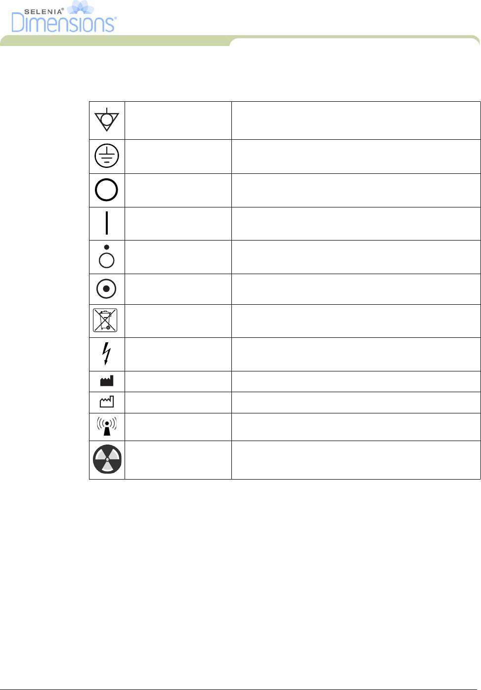
11.0 International Symbols
This section describes the International Symbols on the Selenia Dimensions.
12.0 Document Standards
When prompted to add text, enter the text written in monospaced font exactly as
shown.
Potential Equalization
terminal
Connection for a conductor, except the Protective Earth
terminal, for a direct connection between two or more
pieces of electrical equipment.
Protective Earth
terminal
Connector used for connection to ground of the line cord
or ground cable of the equipment and no other purpose.
Off Power disconnected from the main power source.
On Power connection to the main power source.
Off Only a part of the equipment is disconnected from the
main power source.
On Only a part of the equipment is connected to the main
power source.
WEEE Shows the compliance to the EC Directive on Waste
Electrical and Electronic Equipment (WEEE).
Dangerous Voltage Identifies an area of possible lethal voltage.
Manufacturer
Date of Manufacture
Radio Icon This system transmits non-ionizing radiation
X-ray Radiation Caution—Radiation
DRAFT

xx Part Number MAN-01964
User Manual
Preface
Document Standards
DRAFT
Part Number MAN-01964 1
User Manual
Chapter 1—General Information
System Description
Chapter 1—General Information
1.0 System Description
1.1 Tubestand
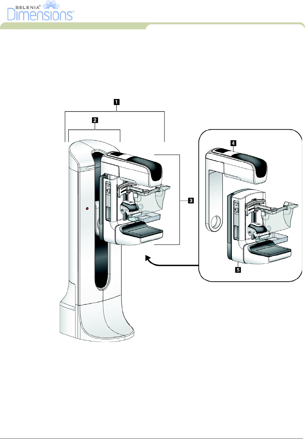
Figure 1-1: Selenia Dimensions
Legend for Figure 1-1
1. Tubestand (Gantry and C-Arm)
2. Gantry
3. C-Arm (Tube Arm and Compression Arm)
4. Tube Arm
5. Compression Arm
DRAFT
2Part Number MAN-01964
User Manual
Chapter 1—General Information
System Description
1.2 Acquisition Workstation
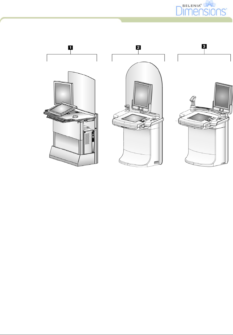
Figure 1-2: Acquisition Workstations
Legend for Figure 1-2
1. Standard Acquisition Workstation
2. Premium Acquisition Workstation
3. Mobile Acquisition Workstation
DRAFT
Part Number MAN-01964 3
User Manual
Chapter 1—General Information
Safety Information
2.0 Safety Information
Read and understand this manual before you use the system. Keep the manual available
during the patient procedures.
Always follow all the instructions in this manual. Hologic does not accept the responsibility
for injury or damage from wrong system operation. Hologic can arrange for training at your
facility.
The Selenia Dimensions has protective devices, but the Technologist must understand how
to safely use the system. The Technologist must remember the health hazards of x-rays.
2.1 General Safety
The Selenia Dimensions system is classified as CLASS I, TYPE B APPLIED PART, IPX0,
permanently connected equipment, continuous operation with short term loading per IEC
60601-1. There are no special provisions to protect the system from flammable anesthetics
or ingress of liquids.
WARNING! Do not open any of the panels. This system contains lethal
voltages.
WARNING! Per North American electrical safety requirements, you
must use a Hospital Grade receptacle to provide a correct
Ground.
WARNING! Electrical equipment used near flammable anesthetics can
cause an explosion.
WARNING! The user must correct problems before the system is used.
The user must arrange for preventive maintenance by an
authorized Service Engineer.
Warning: This device contains dangerous material. Return to Hologic all
material removed from service.
Warning: If a paddle touches possible infectious materials, call your
Infection Control Representative for decontamination
instructions.
DRAFT
4Part Number MAN-01964
User Manual
Chapter 1—General Information
Safety Information
Caution:The system is a medical device and not a normal computer. Do not
make changes to the hardware or software that are not authorized.
Install this device behind a firewall for network security. The
computer virus protection or network security for this medical device
is not provided (for example, a computer firewall). The network
security and anti-virus provisions are the responsibility of the user.
Note… Hologic does not provide the Gantry power cable for some countries. If
the power cable is not provided, the installed cable must meet the
following requirements and all local codes that apply: 3 conductor, 8
AWG (10 mm2) copper not more than 25 feet (7.62 meters) in length.
2.2 Patient Safety
WARNING! After power failure, remove the patient from the system
before you apply power.
WARNING! To keep the isolation quality for the system, attach only
approved accessories or options to the system. Only the
authorized personnel can make changes to the
connections.
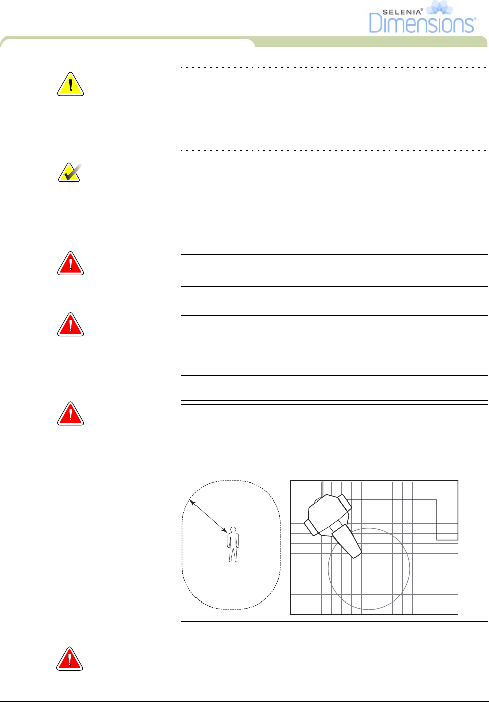
WARNING! Keep a 1.5 meter safe distance between the patient and
any non-patient devices.
Non-patient system components (like the Workflow
Manager, the diagnostic review workstation, or the hard
copy printer) must not be installed in the Patient Area.
Warning: Never leave the patient during the procedure if in contact with
the mammography system.
1.5m
DRAFT
Part Number MAN-01964 5
User Manual
Chapter 1—General Information
Safety Information
Warning: Keep the hands of the patient away from all buttons and
switches at all times.
Warning: The C-Arm movement is motorized.
Warning: You increase the patient dose to high levels if you increase the
AEC exposure adjustment setting. You increase the image noise
or decrease image quality if you decrease the AEC exposure
adjustment setting.
Warning: Put both footswitches away from the patient and C-Arm area to
prevent any accidental footswitch use. When the patient has a
wheelchair, put the footswitches away from the area.
Warning: Control the access to the equipment according to local
regulations for radiation protection.
2.3 Radiation Safety
WARNING! This x-ray system can be dangerous to the patient and the
user. Always follow the safety precautions for x-ray
exposures.
WARNING! The disk drives installed in this system are a Class I Laser
Product. Prevent direct exposure to the beam. Hidden
laser radiation exists if the case to a disk drive is open.
Warning: For exposures except magnification case studies, always use the
Face Shield.
Warning: The Face Shield does not protect from radiation.
DRAFT
6Part Number MAN-01964
User Manual
Chapter 1—General Information
Safety Information
Warning: The bar code scanner installed in this system is a Class II Laser
Product. Prevent direct exposure to the beam. Hidden laser
radiation exists if the cover is opened.
Warning: You must keep your complete body behind the radiation shield
for the time of the exposure for maximum protection from x-ray
exposure.
2.4 Data Loss
Warning: Do not move the C-Arm while the system retrieves the image.
Caution:Never turn off the Acquisition Workstation Circuit Breaker except in
emergency. The circuit breaker can turn off the Uninterruptible Power
Supply (UPS) and risk data loss.
Caution:Do not put any magnetic media near or on devices that create any
magnetic fields, because stored data can be lost.
2.5 Equipment Damage
Caution:Do not put any heat source on the image receptor.
Caution:To minimize possible damage from thermal shock to the Digital Image
Receptor, follow the recommended procedure to turn off the
equipment.
Caution:Do not make any brightness or contrast adjustments to the display
unless the SMPTE test pattern is on the screen.
Caution:Use the least possible amount of cleaning fluids. The fluids must not
flow or run.
Caution:To prevent damage to the electronic components, do not spray
disinfectant on the system.
DRAFT

Part Number MAN-01964 7
User Manual
Chapter 1—General Information
Safety Information
2.6 Emergency Off Switches
The Emergency Off switches remove the power from the Gantry and the Standard
Acquisition Workstation Lift Mechanism. Do not normally use the Emergency Off switches to
turn off the system. See Chapter 2, page 25, for complete information.
2.7 Interlocks
The Selenia Dimensions has safety interlocks:
• The C-Arm vertical drive and rotation is disabled when 45 Newtons (10 pounds) or
greater of compression force is displayed.
• If the x-ray button is released before the end of the exposure, the exposure stops and an
alarm message appears.
• When in Tomo mode, the system does not allow the Grid in the x-ray field
(Tomosynthesis option).
• Mirror and Filter interlocks prevent the x-ray exposure when the Light Field Mirror or the
Filter is not aligned.
DRAFT
8Part Number MAN-01964
User Manual
Chapter 1—General Information
Compliance
3.0 Compliance
This section describes the mammography system compliance requirements and the
responsibilities of the manufacturer.
3.1 Compliance Requirements
The manufacturer has the responsibility for the safety, reliability, and performance of this
equipment with the following provisions:
• The electrical installation of the room meets all requirements.
• The equipment is used according to Instructions for Use.
• The assembly operations, extensions, adjustments, changes, or repairs are performed
only by authorized persons.
• The network and communication equipment must be installed to meet IEC Standards.
The complete system (network and communications equipment and Selenia Dimensions
Mammography System) must be in compliance with IEC 60601-1 and IEC 60601-1-1.
Caution:Medical Electrical Equipment needs special precautions about EMC
and must be installed, put into service and used according to the EMC
information provided.
Caution:Portable and Mobile RF communications can affect Medical electrical
Equipment.
Caution:The use of unauthorized accessories and cables can result in increased
emissions or decreased immunity. To keep the isolation quality for the
system, attach only approved Hologic accessories or options to the
system.
Caution:
The Medical Electrical (ME) Equipment or ME System should not be used
adjacent to or stacked with other equipment. If adjacent or stacked use
is necessary, the ME Equipment or ME System should be observed to
verify normal operation in the configuration in which it is used.
Caution:This system is intended for use by healthcare professionals only. This
system may cause radio interference or may disrupt the operation of
nearby equipment. It may be necessary to take mitigation measures,
such as re-orienting or relocating the equipment or shielding the
location.
Caution:Changes or modifications not expressly approved by Hologic could
void your authority to operate the equipment.
DRAFT

Part Number MAN-01964 9
User Manual
Chapter 1—General Information
Compliance
Caution: This equipment has been tested and found to comply with the limits
for a Class A digital device, pursuant to part 15 of the FCC Rules.
These limits are designed to provide reasonable protection against
harmful interference when the equipment is operated in a commercial
environment. This equipment generates, uses, and can radiate radio
frequency energy and, if not installed and used in accordance with the
instruction manual, may cause harmful interference to radio
communications. Operation of this equipment in a residential area is
likely to cause harmful interference in which case the user will be
required to correct the interference at his own expense.
3.2 Compliance Statements
The manufacturer states this device is made to meet the following requirements:
• CAN/CSA ISO 13485:2003
• CAN/CSA: Medical Electrical Equipment Part 1: C22.2 No. 601.1–M90 (R2005)—
General Requirements for Safety
• EN 60601-1:1990 +A1+A11+A12+A2+A13 Medical Electrical Equipment—General
Requirements for Basic Safety and Essential Performance
• ETSI EN 300 330-1 V1.7.1(2010-02)—Electromagnetic compatibility and Radio spectrum
Matters (ERM); Short Range Devices (SRD); Radio equipment in the frequency range 9
kHz to 25 MHz and inductive loop systems in the frequency range 9 kHz to 30 MHz
• ETSI EN 301 489-1: V1.8.1 (2008-04)—Electromagnetic compatibility and Radio
spectrum Matters (ERM); ElectroMagnetic Compatibility (EMC) standard for radio
equipment and services
• FCC, 47 CFR [Part 15, Subpart C, Section 15.225]
• FDA, 21 CFR [Parts 820, 900 and 1020]
• IEC 60601-1:1988 +A1+A2:1995Medical Electrical Equipment—General Requirements
for Safety
• IEC 60601-1-1:2000 Medical Electrical Equipment—Collateral Standard: Safety
Requirements for Medical Electrical Systems
• IEC 60601-1-2:2007 Medical Electrical Equipment—Collateral Standard:
Electromagnetic Compatibility for Medical Electric Systems
• IEC 60601-1-3:1994 Medical Electrical Equipment—Collateral Standard: Requirements
for Radiation Protection in Diagnostic X-ray Equipment
• IEC 60601-1-4:1996 +A1:1999 Medical Electrical Equipment—Collateral Standard:
Programmable Electrical Medical Systems
• IEC 60601-2-28:1993 Medical Electrical Equipment—Particular Requirements for the
Safety of X-ray Source Assemblies and X-ray Tube Assemblies for Medical Diagnosis
• IEC 60601-2-32:1994 Medical Electrical Equipment—Particular Requirements for the
Safety of Associated Equipment of X-ray Equipment
• IEC 60601-2-45:2001 Medical Electrical Equipment—Particular Requirements for the
Safety of Mammographic X-ray Equipment and Mammographic Stereotactic Devices
• RSS-210: Issue 7, 2007
• UL 60601-1 1st Edition: Medical Electrical Equipment, Part 1—General Requirements
for Safety
DRAFT
10 Part Number MAN-01964
User Manual
Chapter 1—General Information
Label Locations
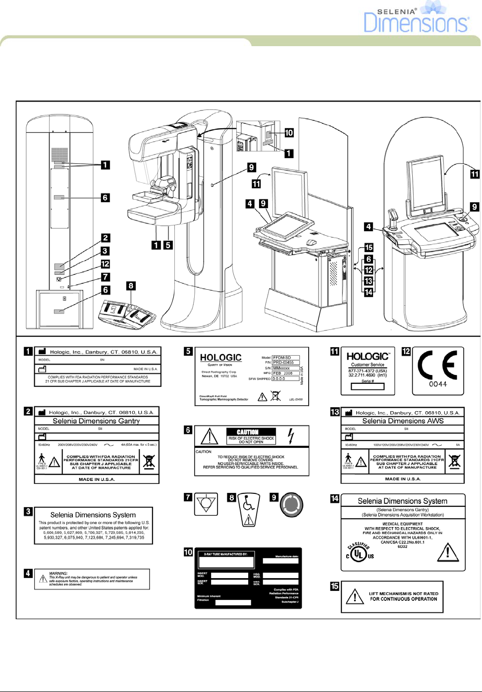
4.0 Label Locations
Figure 1-3: Label Locations
DRAFT
Part Number MAN-01964 11
User Manual
Chapter 2—System Controls and Indicators
System Power Controls
Chapter 2—System Controls and Indicators
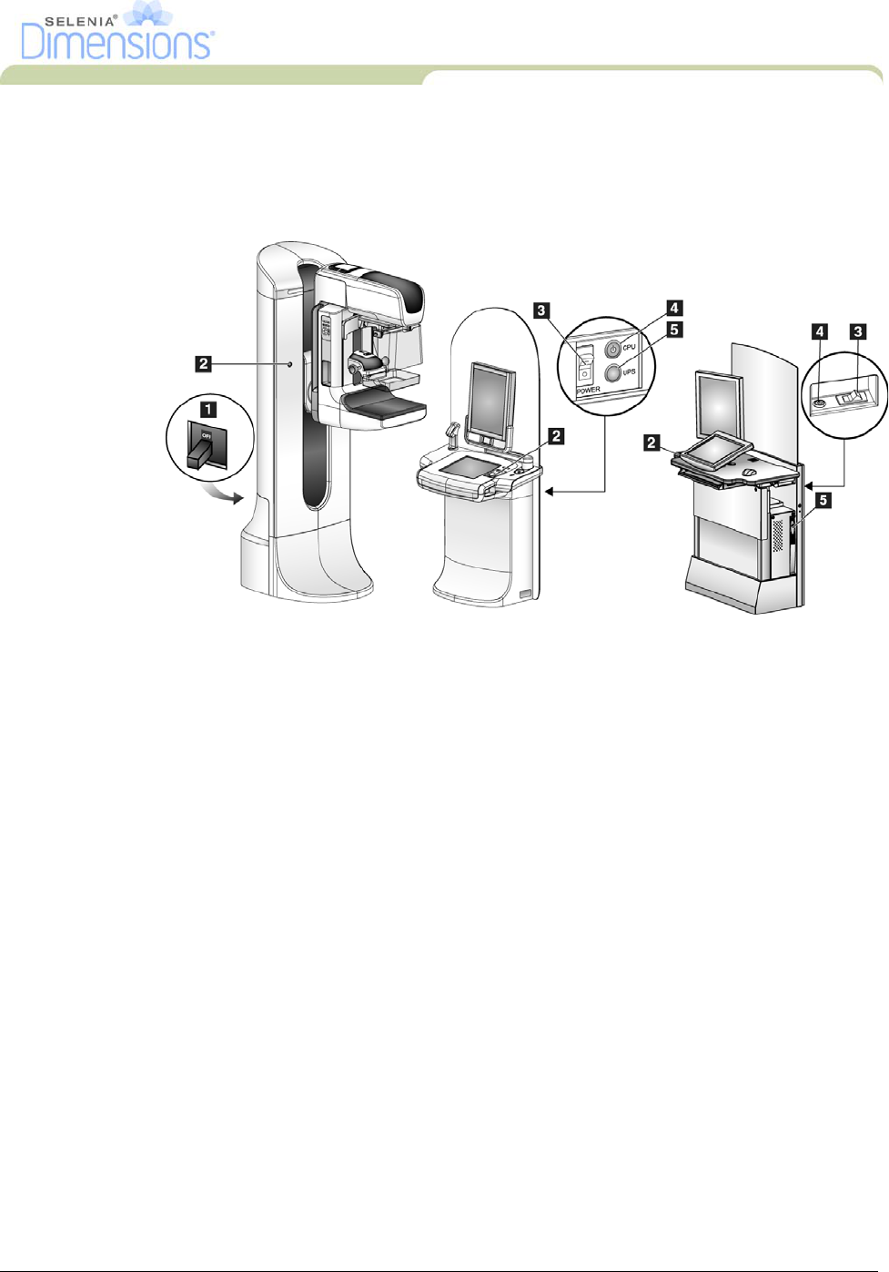
1.0 System Power Controls
Figure 2-1: System Power Controls
Legend for Figure 2-1
1. Gantry Power Circuit Breaker
2. Emergency Off Switch (two on the Gantry, one on the Acquisition Workstation)
3. Acquisition Workstation Power Circuit Breaker
4. Computer Power Button
5. UPS Power Button
DRAFT
12 Part Number MAN-01964
User Manual
Chapter 2—System Controls and Indicators
Acquisition Workstation Controls and Indicators
2.0 Acquisition Workstation Controls and Indicators
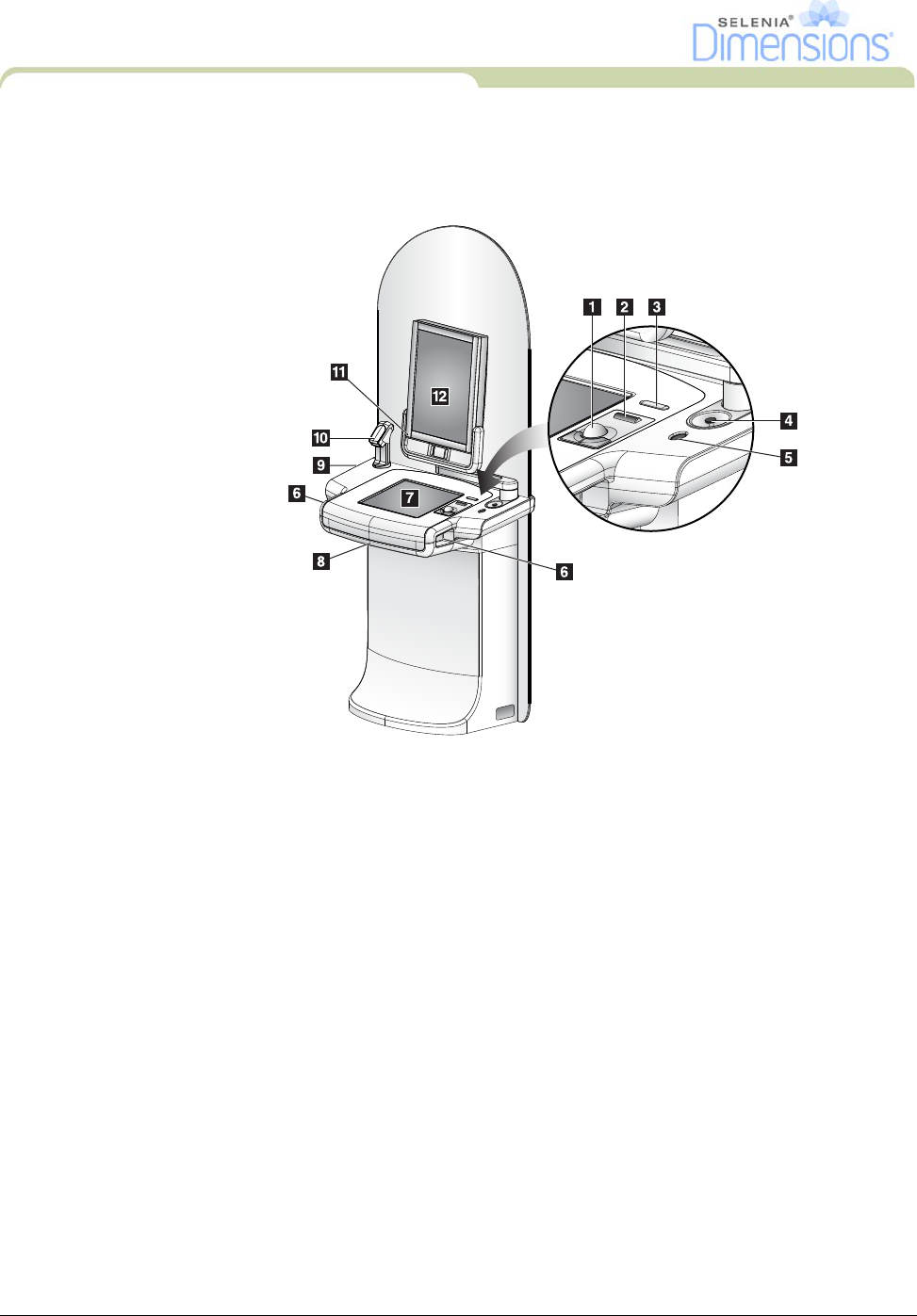
2.1 Premium Acquisition Workstation Controls and Displays
Figure 2-2: Premium Acquisition Workstation Controls and Displays
Legend for Figure 2-2
1. Trackball
2. Scroll Wheel
3. Compression Release
4. Emergency Off Switch
5. Fingerprint Scanner
6. X-Ray Button (one on each side)
7. Touchscreen Display
8. Keyboard (in drawer)
9. CD/DVD Drive
10. Bar Code Scanner
11. LED for Preview Display Power
12. Preview Display
DRAFT
Part Number MAN-01964 13
User Manual
Chapter 2—System Controls and Indicators
Acquisition Workstation Controls and Indicators
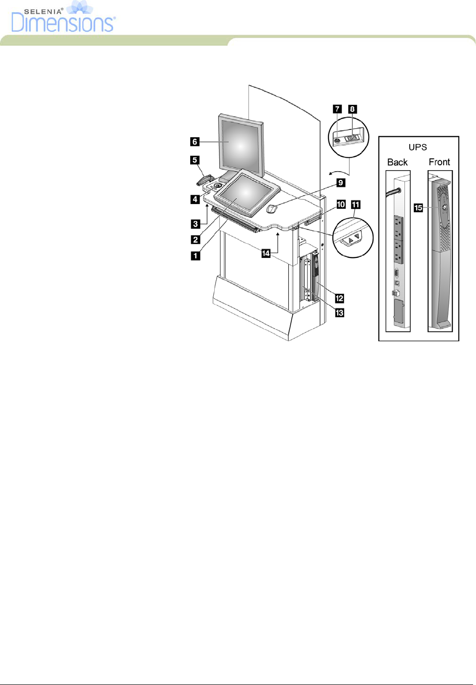
2.2 Standard Acquisition Workstation Controls and Displays
2.3 Keyboard
Use the keyboard in the front drawer of the Acquisition Workstation for data entry.
2.4 Bar Code Scanner
Use this device for data entry from bar codes for patient or procedure records.
2.5 Premium Acquisition Workstation Touchscreen Display
Use the Touchscreen or trackball to select items.
2.6 Standard Acquisition Workstation Control Display
Use the Mouse to select items.
2.7 Preview Display
See the images on the Preview Display.
Legend for Figure 2-3
1. Keyboard
2. Control Display
3. Left X-Ray Switch
4. Emergency Off Switch
5. Bar Code Scanner (Optional)
6. Preview Display
7. CPU Reset Switch
8. Circuit Breaker Power On
Switch
9. Mouse
10. DVD Drive
11. Height Adjustment Switch
12. UPS
13. Computer
14. Right X-Ray Switch
15. UPS Power Button
Figure 2-3: Standard Acquisition Workstation Controls and Displays
DRAFT
14 Part Number MAN-01964
User Manual
Chapter 2—System Controls and Indicators
Tubestand Controls and Indicators
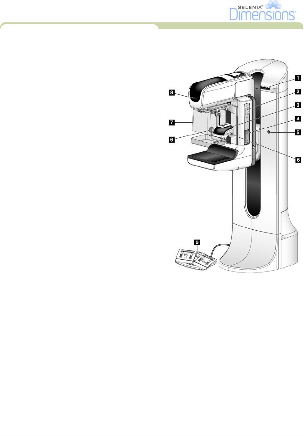
3.0 Tubestand Controls and Indicators
Legend for Figure 2-4
1. Rotation Angle Displays (each side)
2. C-Arm Controls (each side)
3. Compression Device
4. Patient Handles (each side)
5. Emergency Off Switches (each side)
6. Compression Handwheels
7. Patient Face Shield
8. Tubehead Display
9. Footswitches
Figure 2-4: Tubestand Controls and Indicators
DRAFT
Part Number MAN-01964 15
User Manual
Chapter 2—System Controls and Indicators
Tubestand Controls and Indicators
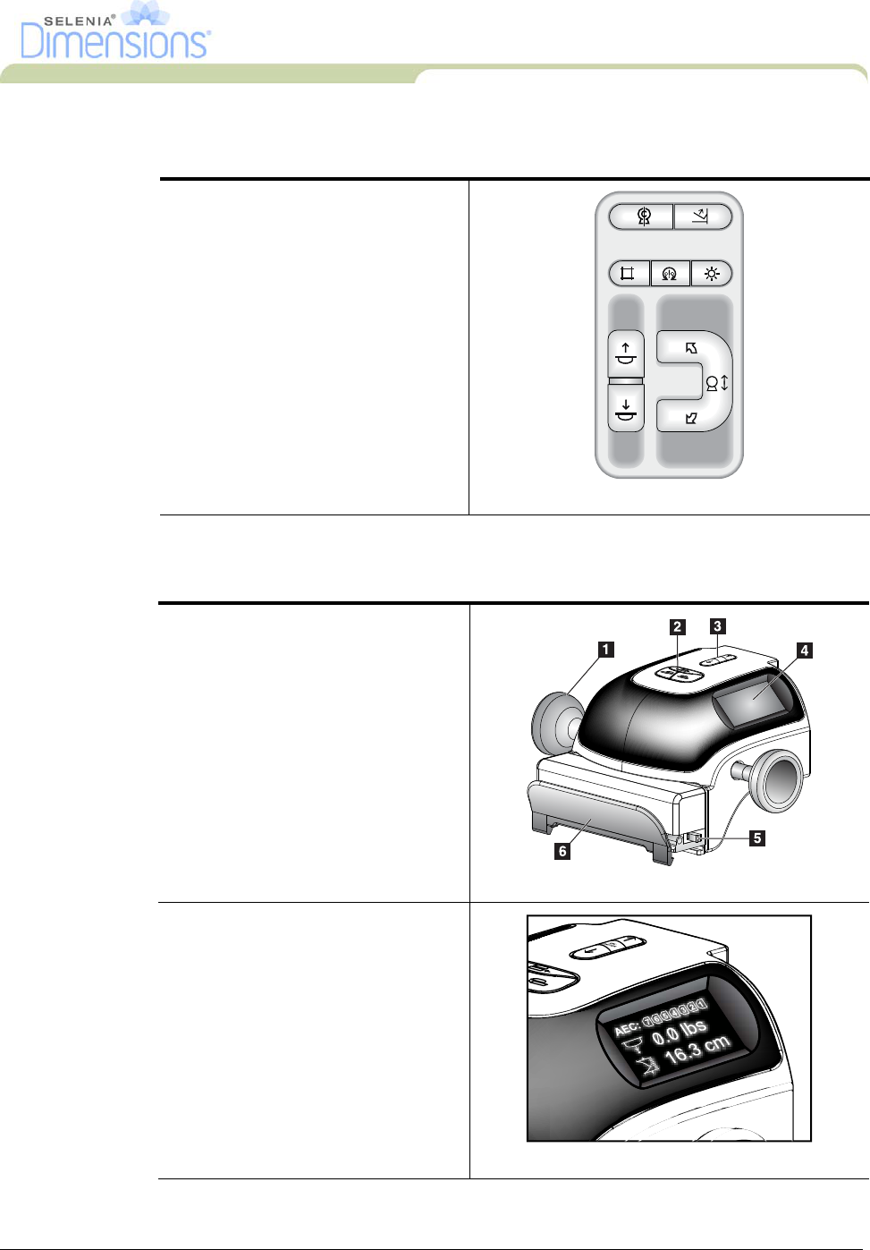
3.1 C-Arm Controls
3.2 Compression Device Controls and Displays
The C-Arm Controls provide the
Collimator and C-Arm functions.
See Section 6.0, page 19.
Figure 2-5: C-Arm Controls
Legend for Figure 2-6
1. Manual Compression Handwheels
2. Paddle Shift Buttons
3. AEC Sensor Buttons
4. Compression Device Display
5. The FAST Compression Mode Slide
6. Paddle Clamp
Figure 2-6: Compression Device
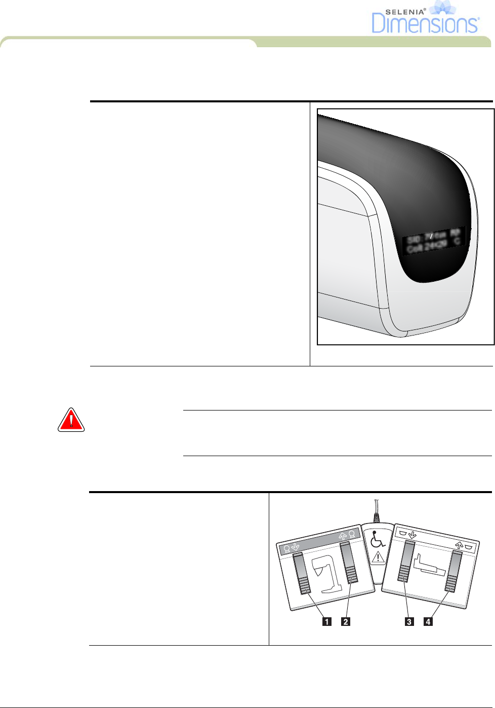
The Display on the compression
device shows:
• AEC Sensor Position
• Compression Force (displays 0.0
when force is less than 4 pounds)
• Compression Thickness
• Angle of C-Arm after rotation (for
5 seconds)
Figure 2-7: Compression Display
AEC
POSITION
DRAFT
16 Part Number MAN-01964
User Manual
Chapter 2—System Controls and Indicators
Tubestand Controls and Indicators
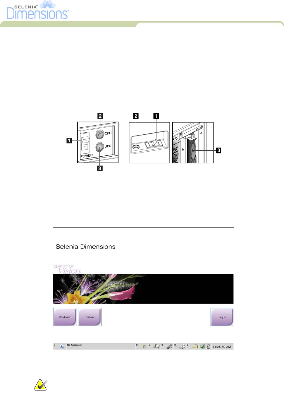
3.3 Tubehead Display
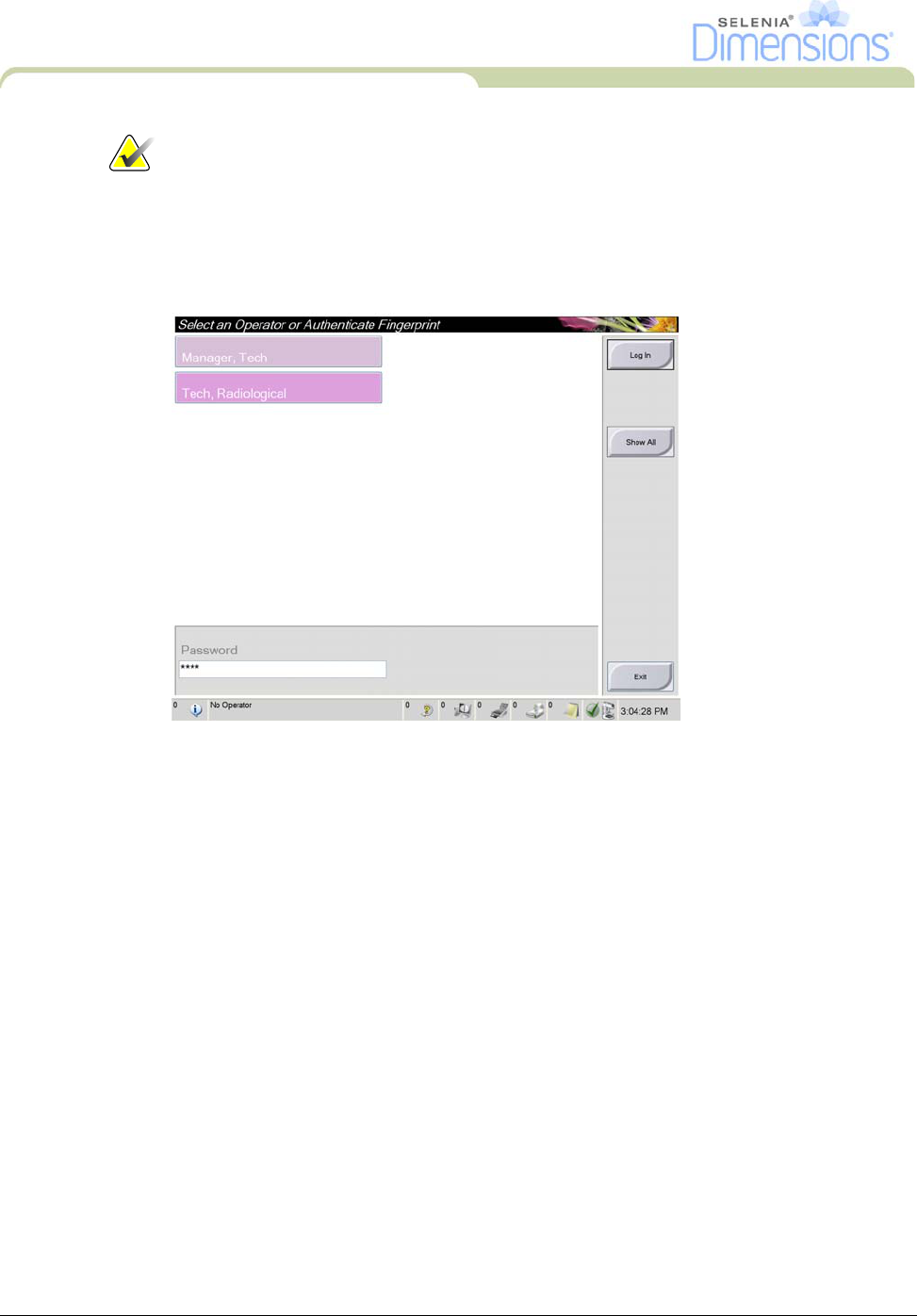
3.4 Dual Function Footswitches
Warning: Put both footswitches away from the patient and C-Arm area to
prevent any accidental footswitch use. When the patient has a
wheelchair, put the footswitches away from the area.
The Tubehead Display shows:
•SID
• Filter Type
• Collimator Setting
• Paddle Position
Figure 2-8: Tubehead Display
SID: 70 cm Rh
Coll: 24x29 C
To use the footswitches:
1. Press the footswitch to actuate.
2. Release the switch to stop the
movement.
Legend for Figure 2-9
1. C-Arm Down
2. C-Arm Up
3. Compression Down
4. Compression Up
Figure 2-9: Dual Function Footswitches
COMPRESSION
C-ARM
DRAFT
Part Number MAN-01964 17
User Manual
Chapter 2—System Controls and Indicators
How to Turn On the Selenia Dimensions
4.0 How to Turn On the Selenia Dimensions
4.1 Preparation
1. Reset all three Emergency Off switches.
2. Make sure that both system circuit breakers are in the On position.
3. Remove any obstructions to the C-Arm movement and to the view of the Operator.
4.2 Startup
1. If the UPS was shut down, press the UPS power button (at the rear of the Premium
Acquisition Workstation or on the side of the Standard Acquisition Workstation).
2. Press the computer power button at the rear of the Acquisition Workstation.
Figure 2-12: The Startup Screen
3. Select the Log In button.
Note… The Startup screen includes a Shutdown button that turns off the
system, and a Reboot button that restarts the system.
Figure 2-10: Premium
Acquisition Workstation
Power Buttons
Figure 2-11: Standard Acquisition
Workstation Power Buttons
Legend for Figure 2-10
and Figure 2-11
1. Acquisition
Workstation Circuit
Breaker
2. Computer Power
Button
3. UPS Power Button
DRAFT
18 Part Number MAN-01964
User Manual
Chapter 2—System Controls and Indicators
How to Change the Language
Note…
The system requires between five minutes and forty-five minutes to
prepare for image acquisition. The wait time depends on the detector
power configuration. A timer in the Taskbar displays the wait time before
the system is ready. Do not acquire clinical or QC images unless the
System Status Icon indicates the system is Ready.
4.3 Log In
Figure 2-13: How to Log In
When the user Log In screen displays, all Managers and Technologists show in the list of
Operators.
1. To display the Service, Applications, and Physicists user names, select the Show All
button.
2. Select your user name, enter your password, and select the Log In button.
Or
Validate your fingerprint.
5.0 How to Change the Language
1. Select the Admin button.
2. Select the My Settings option.
3. From the Locale field, select a language from the drop-down menu.
4. Select the Save button, then select the OK button to the Update Successful message. The
selected language displays.
DRAFT
Part Number MAN-01964 19
User Manual
Chapter 2—System Controls and Indicators
Perform the Functional Tests
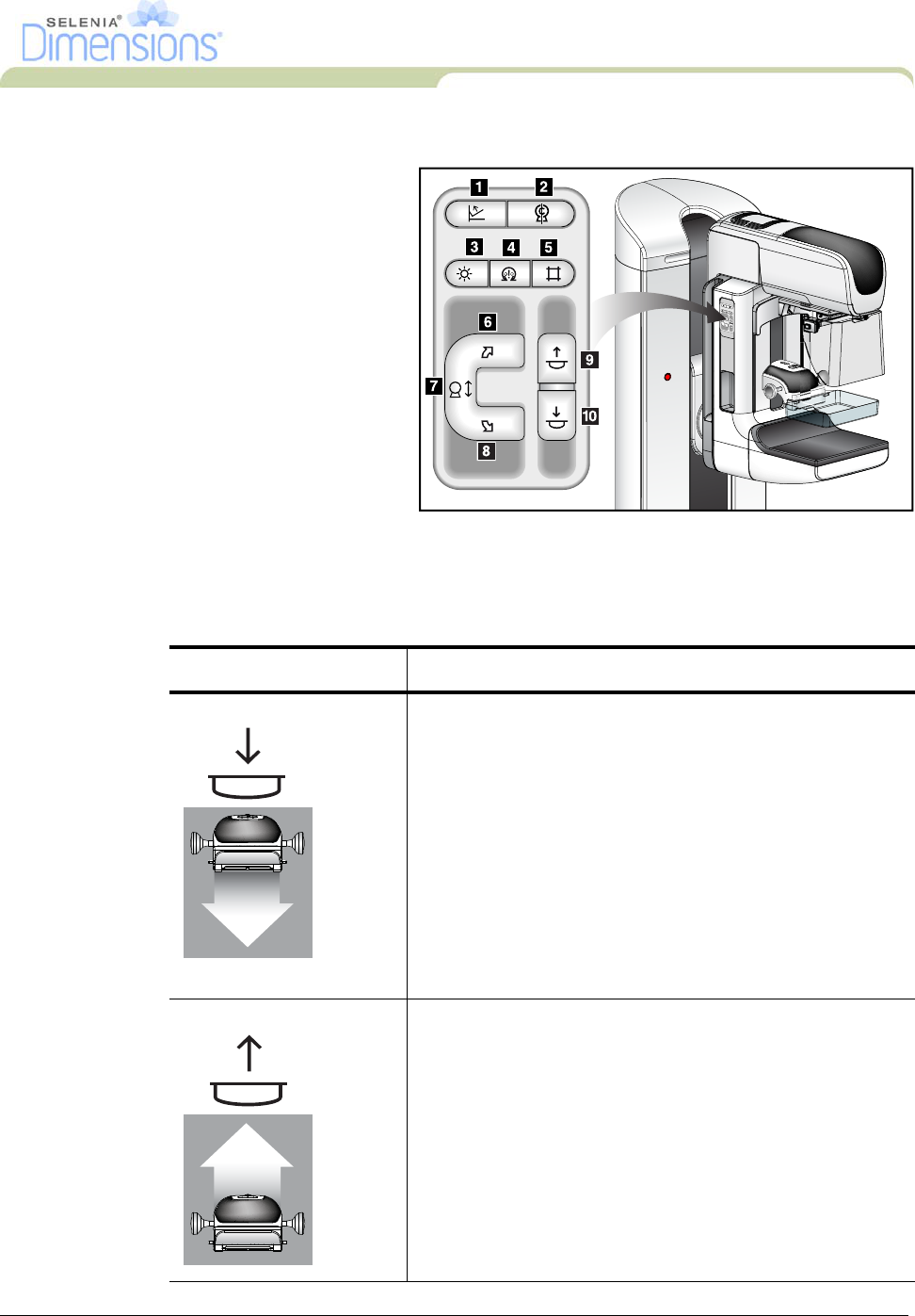
6.0 Perform the Functional Tests
Perform the Functional Tests as part of your monthly visual checklists to make sure that the
control operates correctly.
Legend for Figure 2-14
1. Compression Release
2. (Provisional use)
3. Light Field Lamp
4. (Provisional use)
5. Collimator Override
6. Clockwise C-Arm Rotation
7. C-Arm Up and Down
8. Counterclockwise C-Arm
Rotation
9. Compression Up
10. Compression Down
A C-Arm control panel is on
both the left and right sides
of the Gantry. Figure 2-14: C-Arm Controls (left side shown)
Table 2-1: C-Arm Functional Tests
Function Functional Test
Compression Down Press a Compression Down button:
• The compression brake engages.
• The light field lamp illuminates.
• The compression device lowers.
Note… When you press the Compression Down button, the
compression brake remains engaged until the Compression
Release button is pressed.
Compression down movement stops:
• When you release the button.
• When you reach the Down Force limit.
• When you reach the lower travel limit.
Compression Up Press a Compression Up button:
• The Compression Device moves toward the top.
• The Compression Up button does not release the
Compression Brake.
Compression Up movement automatically stops:
• When you release the button.
• When you reach the upper travel limit.
DRAFT
20 Part Number MAN-01964
User Manual
Chapter 2—System Controls and Indicators
Perform the Functional Tests
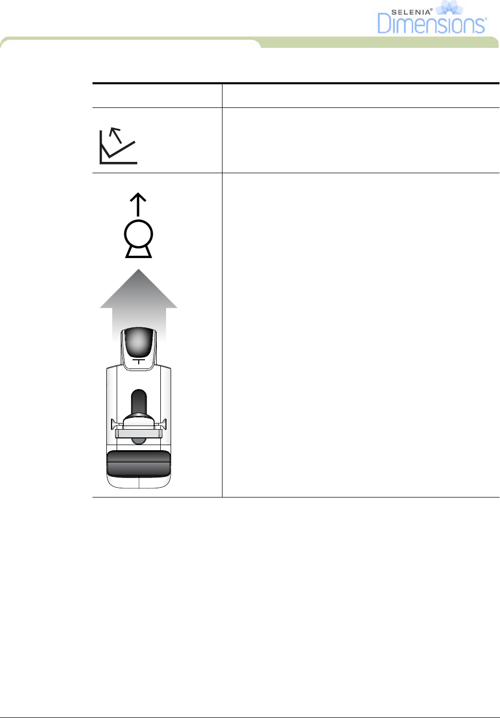
Compression Release Press the Compression Release button:
• The Compression Motor Brake releases.
• The Compression Device lifts.
C-Arm Up Press the C-Arm Up button:
• The C-Arm movement automatically stops when the
button is released.
• The C-Arm movement automatically stops when the
C-arm reaches the upper travel limit.
• The C-Arm movement is disabled when a compression
force of 45 N (10 pounds) or greater is applied.
Table 2-1: C-Arm Functional Tests
Function Functional Test
DRAFT