Home Automation OMNISTAT-Z Z-Wave Thermostat User Manual Installation Manual
Home Automation Inc Z-Wave Thermostat Installation Manual
UserManual.wiki
>
Home Automation
>
OMNISTAT-Z User Manual
>
Installation Manual
Contents
1.
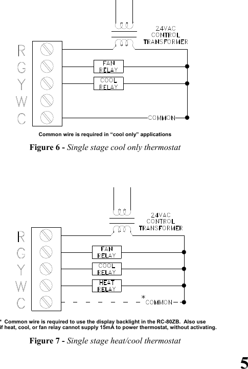
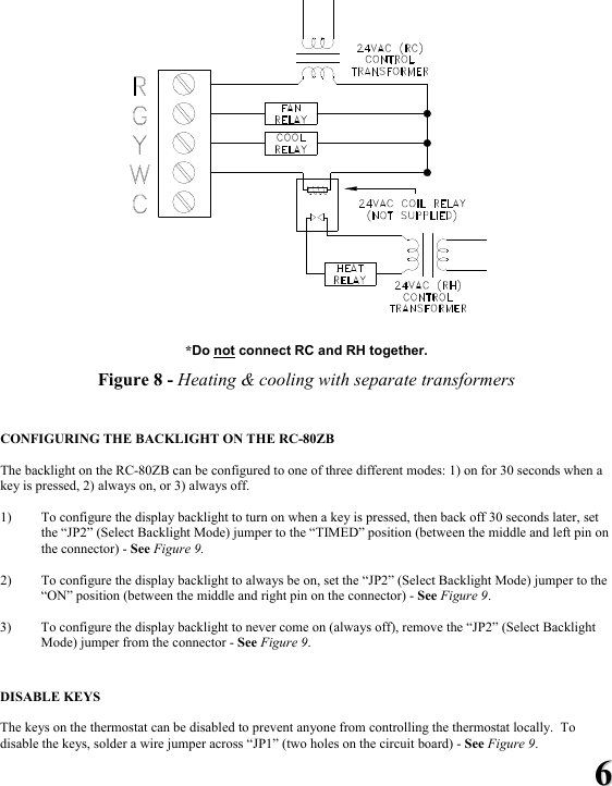
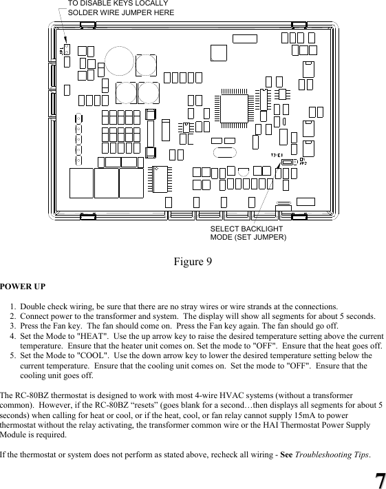
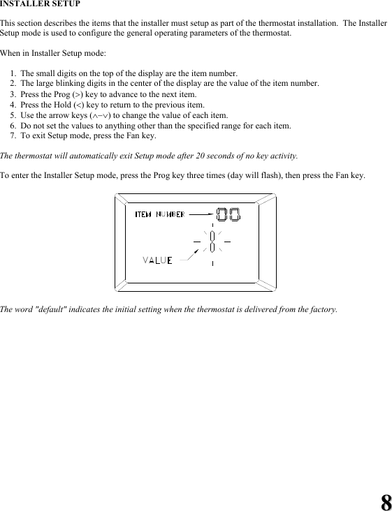
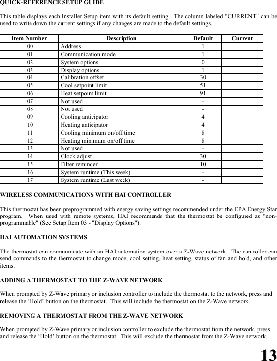
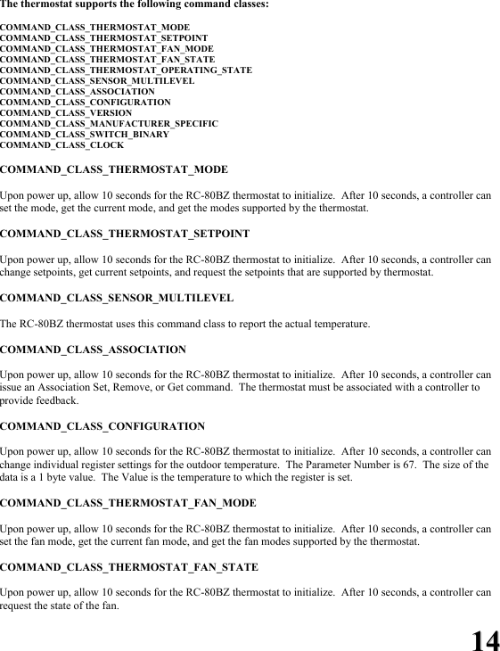
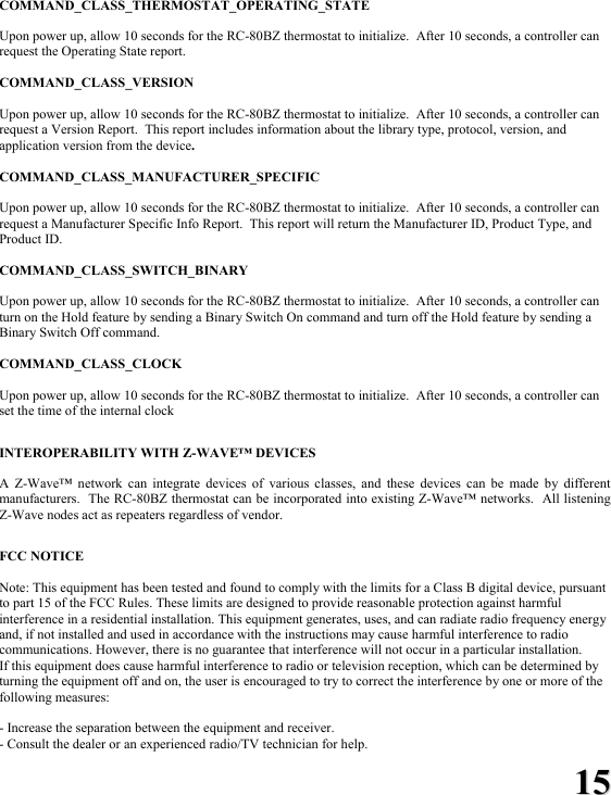
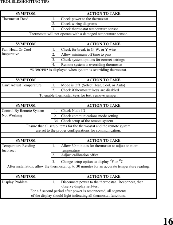
Installation Manual
2.
Owners Manual
Installation Manual
Navigation menu
Upload a User Manual
Namespaces
Wiki Guide
HTML
PDF
Info
Views
User Manual
Discussion / Help
Navigation