HomeScenario HSC000000A1 Advanced Scenario Hub/Music Server User Manual HSC 300
HomeScenario, Inc Advanced Scenario Hub/Music Server HSC 300
UserManual.wiki
>
HomeScenario
>
HSC000000A1 User Manual
user manual
Navigation menu
Upload a User Manual
Namespaces
Wiki Guide
HTML
PDF
Info
Views
User Manual
Discussion / Help
Navigation
![togglesequencerlightvariablestop4.2.4 Function Each node provides several actions which can be called by connected to any signals. In addition, a scenario can be treated as the function in the traditional language as well. Each scenario can be enabled or disabled by its enable action. [FIXME: Add an example here] 4.3 Scenario listIn order to make the scenarios more readable, we can separate rules into different scenarios. In the Scenario viewer, all scenarios are listed. We can add/delete/enable/disable them individually. 4.3.1 Add a new scenario We can add a new scenario by clicking the “Add” icon in the top of the screen.[screenshot of the scenario viewer] 4.3.2 Edit existing scenario Click the scenario will enter the scenario editor.](https://usermanual.wiki/HomeScenario/HSC000000A1/User-Guide-1215532-Page-26.png)
![[Ask iap provide description] 4.7.3 real-time timer [Ask iap provide description] 4.7.4 daily timer [Ask iap provide description] 4.8 Comparator The comparator device is used to compare the value of two inputs. [Ask iap provide description] 4.8.1 Min/Max [Ask iap provide description] 4.8.2 Range [Ask iap provide description] 4.9 Logic devices Logic device provides LogicJoin action that we be connected to several states. It will emit state and signal change when the result of logic operation of the devices changes. For example, an AND device will perform logic AND operation for its input and generate signals when the result is changed from True to False or from Fase to the True. Currently, we support the following virtual logic devices. z AND](https://usermanual.wiki/HomeScenario/HSC000000A1/User-Guide-1215532-Page-34.png)
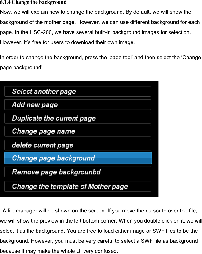
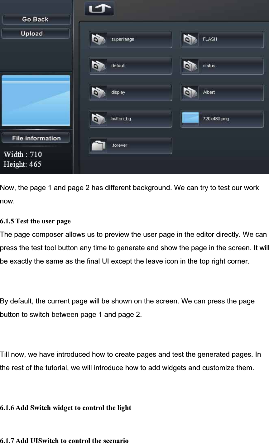
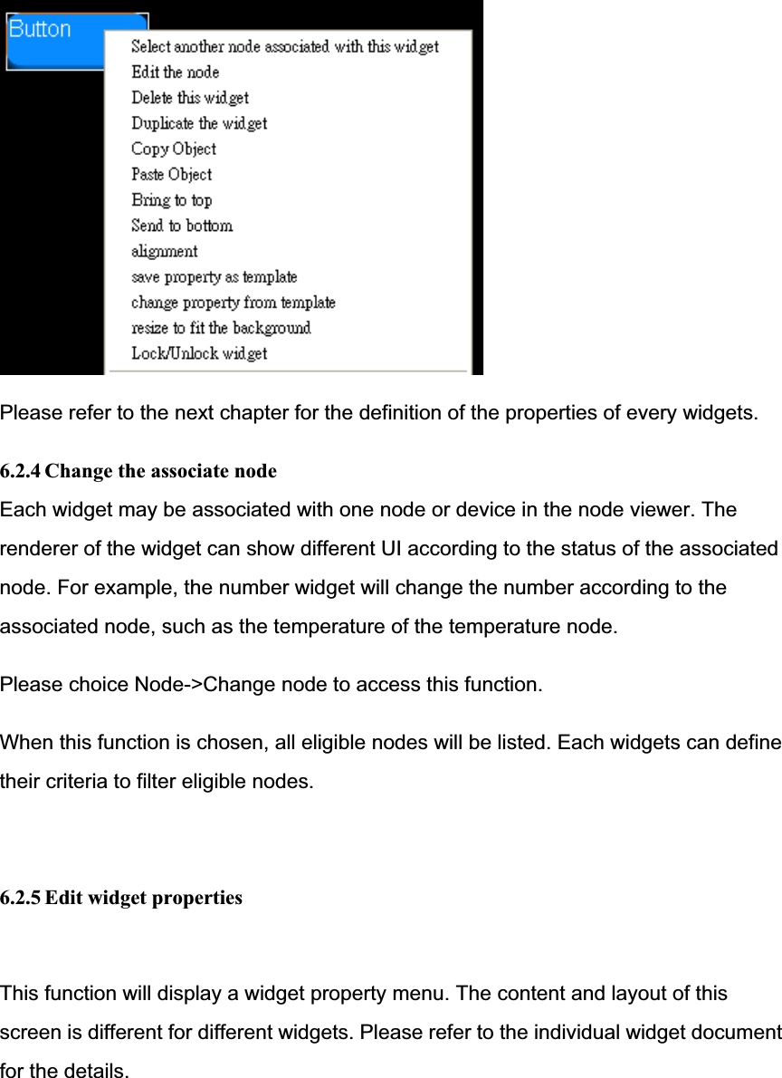
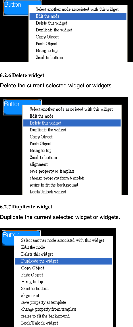
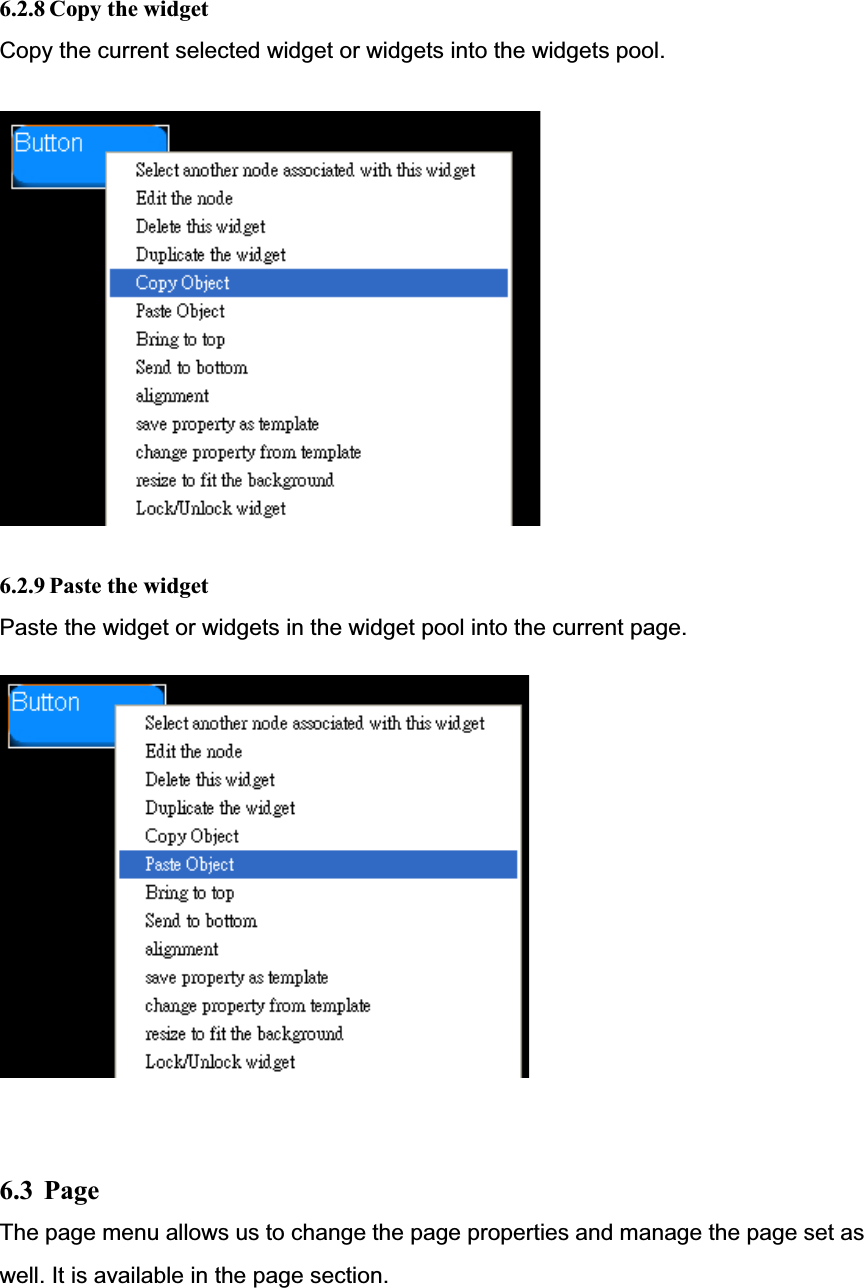
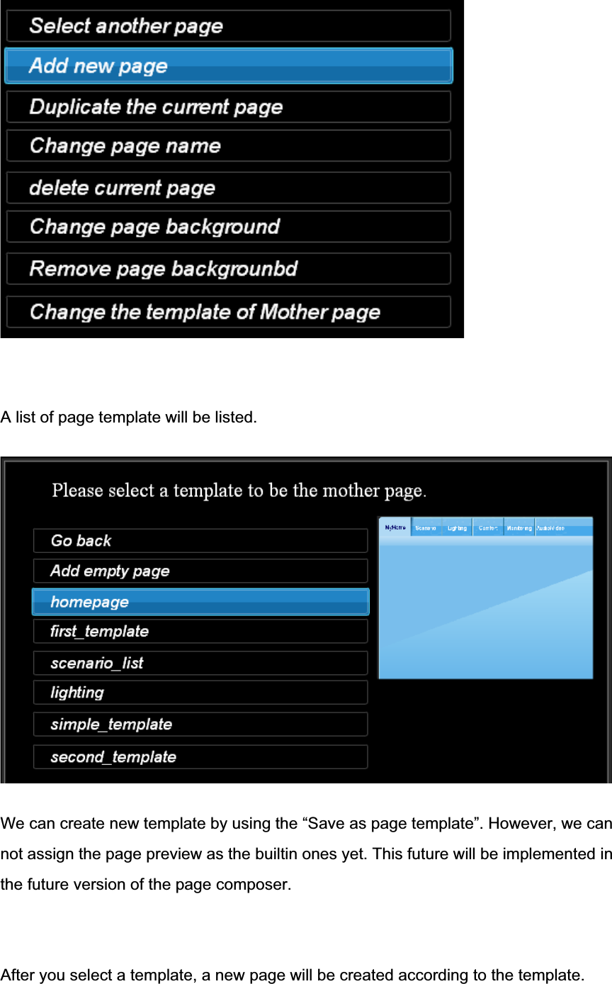
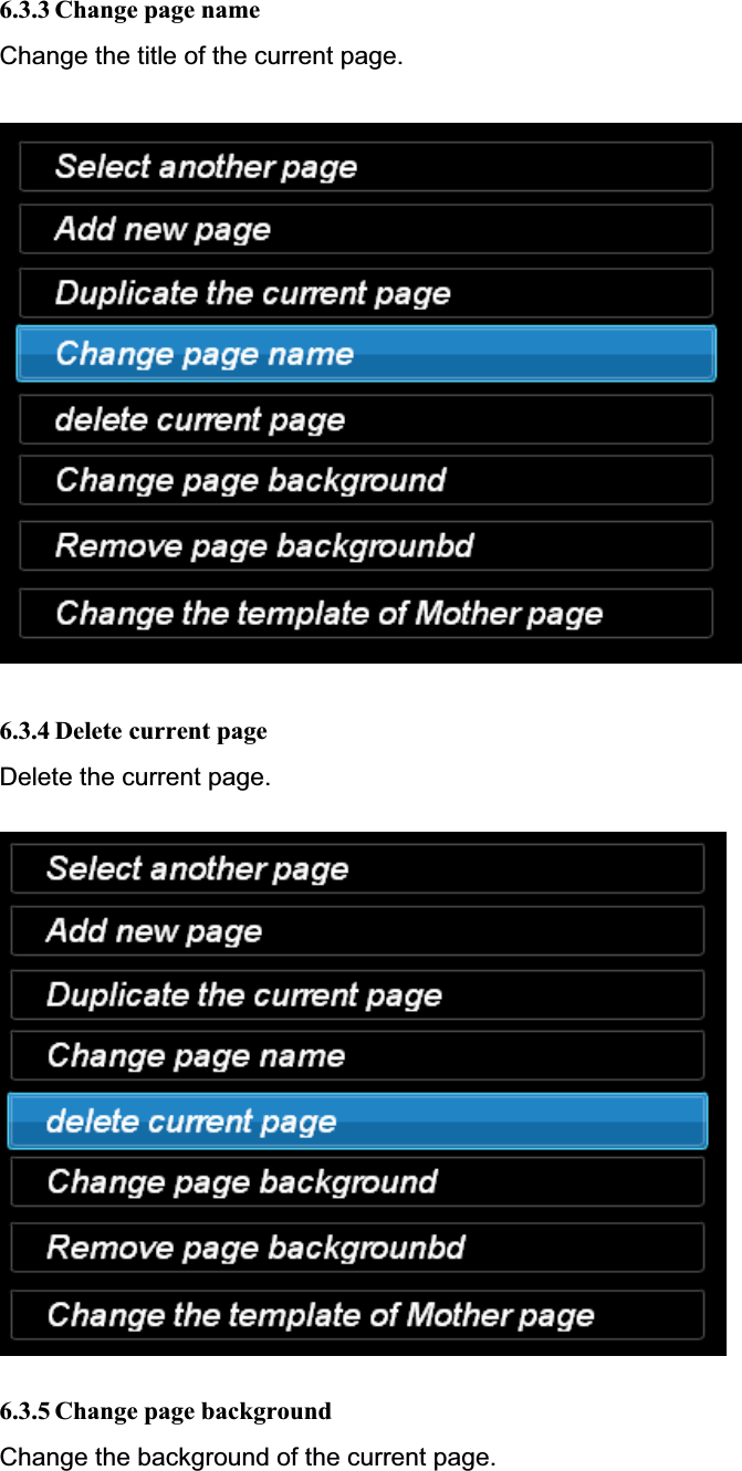
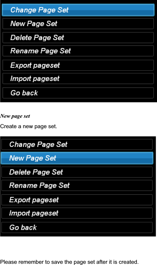
![When you enter the page composer, it will load the first page. If the first page is not available, the Mother page will be loaded. The Mother page contains background and widgets that will be duplicated in every page. A common usage is to put all page buttons in the Mother page so that we can switch to any page from any page. In addition to the widgets, we can put the background in the Mother page as well. If any page is not defined a background, we will use the background of Mother page. In this tutorial, please place two page buttons in the Mother page and load the background on it. [Put the screen shot here] Since there is no page yet, the page button will be empty. Don’t worry. We can assign the page to it latter. 6.1.2 Add/delete/edit user pages The goal of the page composer is to create UI for the HSC-200. It can create multiple pages and link those pages by using the page button widget. A page button looks like a normal button on the UI. It can show the name of the page inside it. When user click it, the UI will load the page associated with the button as the current page. All page related functions are grouped in the page tool button. [Put the screenshot of the page tool button here] Initially, we have only one Mother page only. We need to create a new page by selecting the ‘Add new page’ inside the page tool. Once a page is created, we can place widgets inside it. Please create two pages. 6.1.3 Associate page button with page](https://usermanual.wiki/HomeScenario/HSC000000A1/User-Guide-1215532-Page-40.png)
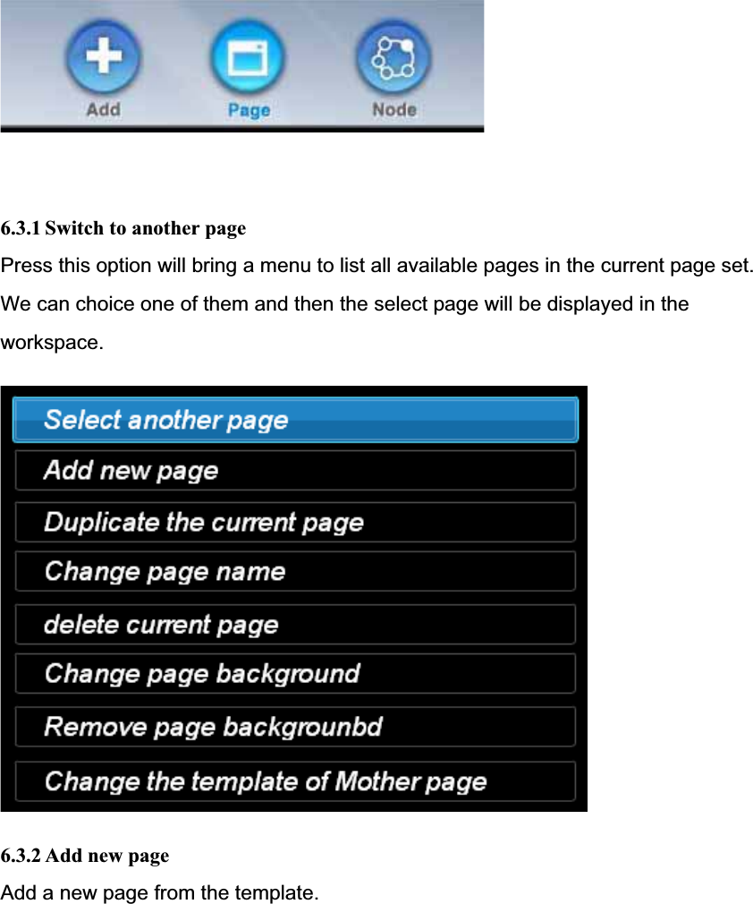
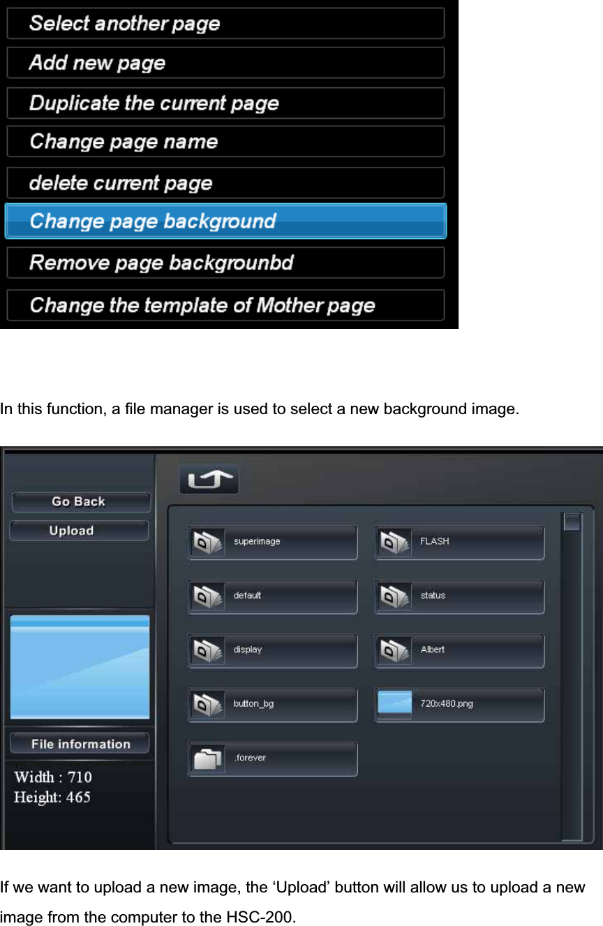
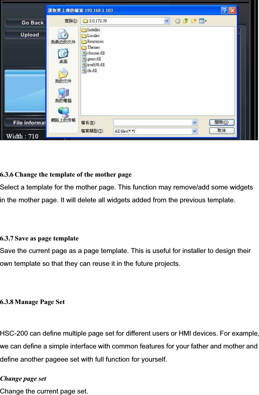
![In the node property menu, we can change the associated page by clicking the ‘Select another page’ item. All pages will be listed. The page switch button is composed of z One normal background image z One click background image z One title: The name of the associated page. We can hide background or the title in the setting page. The page switch button is often used at the mother page so that users can click them to switch between all pages. However, we can use them to switch back and forth between two pages as well. 7.3.1 Add a page switch button 7.3.2 Setting page of the page switch In the setting page, we have the following options. z Change the normal background z Change the click background z Hide background or title z Change text color z Change font z Change text position Change the background [snapshot here] This option allows us to change the background of the page switch. You can use the file manager to pick the image. The page switch widget will scale the image to fit the defined size. However, it’s better to keep the original size for the performance and quality issue.](https://usermanual.wiki/HomeScenario/HSC000000A1/User-Guide-1215532-Page-63.png)
![Please refer to the file manager section for the usage of the file manager. Hide background or title The page switch allow us to disable title or background individually. If both are disabled, this widget will become invisible. However, it will still capture the mouse events. This is useful to define a click area around the buttons in the background. Change text colot [snapshot here] The color of the title can be changed here. Change font The font used to show the title can be changed here. Change text position This option can change the location of the title in the widget. You can set the location manually or select the align left/right/up/down/center for both vertically and horizontally. 7.3.3 Use SWF file as background The page switch widget can accept the SWF file as the background. Under this mode, the SWF will be loaded as MovieClip bg in the page switch widget. Therefore, you can access all variables and functions defined in the widget. The following is a list which you may be interesting. The complete list is available in the page widget authoring guide.z _parent.Nodez _parent.Click() Call this function will switch to the page defined by the page composer. 7.4 Text widget](https://usermanual.wiki/HomeScenario/HSC000000A1/User-Guide-1215532-Page-64.png)