Honda R and D 70410-QAB Wireless Access Point User Manual
Honda R&D; Co., Ltd. Wireless Access Point Users Manual
UserManual.wiki
>
Honda R and D
>
70410 QAB User Manual
Users Manual
Navigation menu
Upload a User Manual
Namespaces
Wiki Guide
HTML
PDF
Info
Views
User Manual
Discussion / Help
Navigation
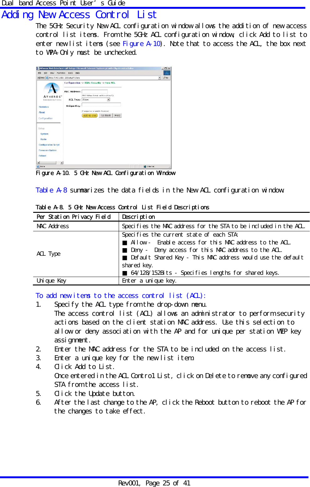
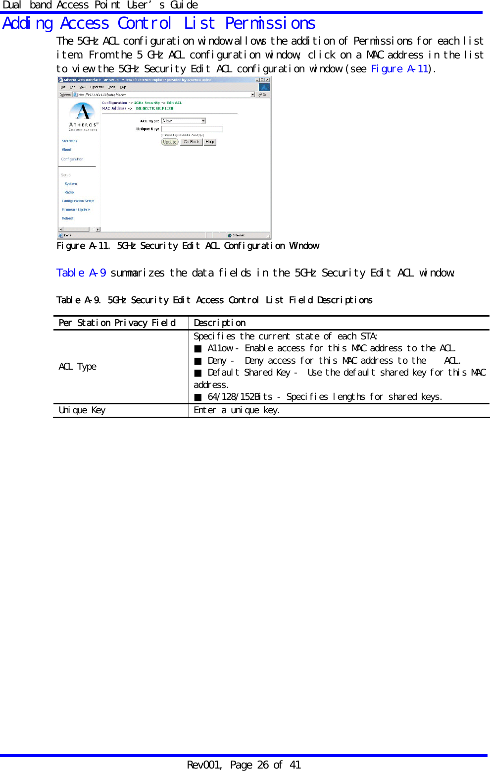
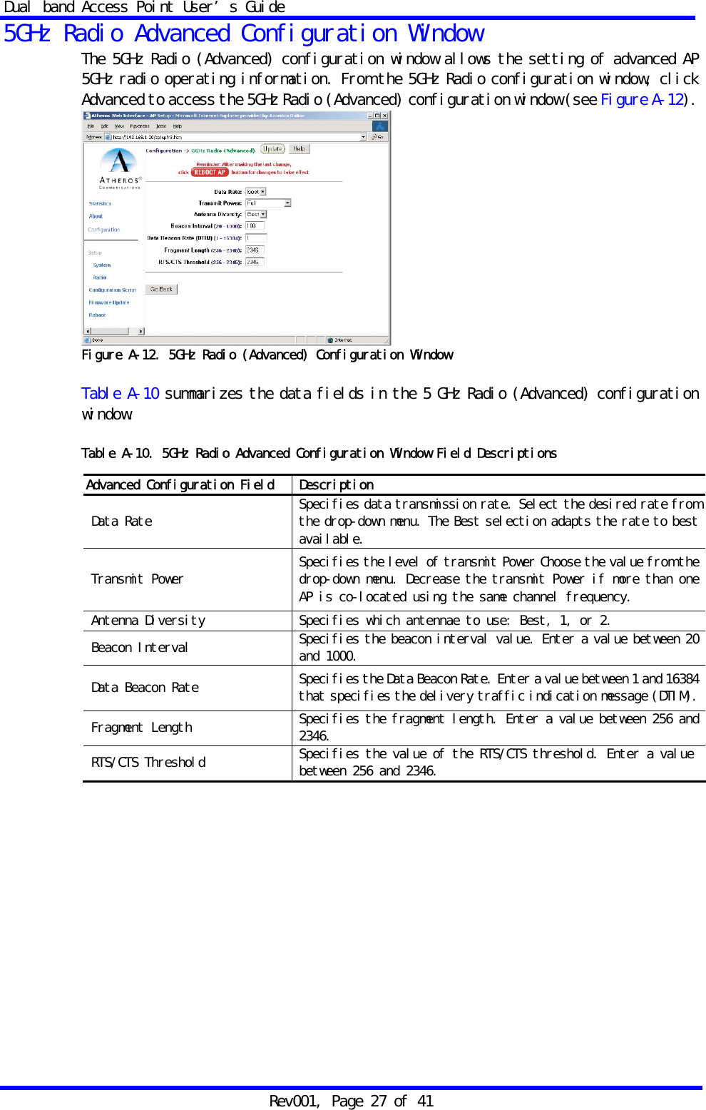
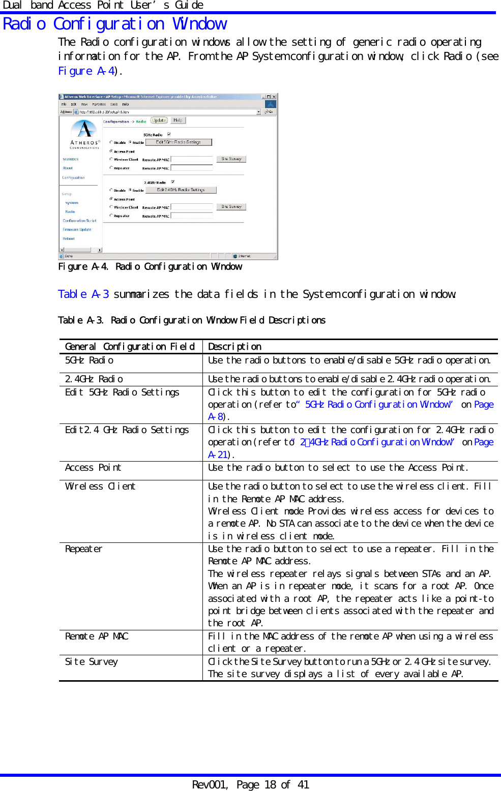
![Dual band Access Point User’s Guide Rev001, Page 4 of 41 Declaration of Conformity with Regard to the R&TTE Directive 1999/5/EC Česky [Czech] HONDA tímto prohlašuje, že tento 70410-QAB je ve shodě se základními požadavky a dalšími příslušnými ustanoveními směrnice 1999/5/ES. Dansk [Danish] Undertegnede HONDA erklærer herved, at følgende udstyr 70410-QAB overholder de væsentlige krav og øvrige relevante krav I direktiv 1999/5/EF. Deutsch [German] Hiermit erklärt HONDA dass sich das Gerät 70410-QAB in Übereinstimmung mit den grundlegenden Anforderungen und den übrigen einschlägigen Bestimmungen der Richtlinie 1999/5/EG befindet. Eesti [Estonian] Käesolevaga kinnitab HONDA seadme 70410-QAB vastavust direktiivi 1999/5/EÜ põhinõuetele ja nimetatud direktiivist tulenevatele teistele asjakohastele sätetele. English Hereby, HONDA declares that this 70410-QAB is in compliance with the essential requirements and other relevant provisions of Directive 1999/5/EC. Español [Spanish] Por medio de la presente HONDA declara que el 70410-QAB cumple con los requisitos esenciales y cualesquiera otras disposiciones aplicables o exigibles de la Directiva 1999/5/CE. Ελληνική [Greek] ΜΕ ΤΗΝ ΠΑΡΟΥΣΑHONDA ∆ΗΛΩΝΕΙ ΟΤΙ70410-QAB ΣΥΜΜΟΡΦΩΝΕΤΑΙ ΠΡΟΣ ΤΙΣ ΟΥΣΙΩ∆ΕΙΣ ΑΠΑΙΤΗΣΕΙΣ ΚΑΙ ΤΙΣ ΛΟΙΠΕΣ ΣΧΕΤΙΚΕΣ ∆ΙΑΤΑΞΕΙΣ ΤΗΣ Ο∆ΗΓΙΑΣ 1999/5/ΕΚ. Français [French] Par la présente HONDA déclare que l'appareil 70410-QAB est conforme aux exigences essentielles et aux autres dispositions pertinentes de la directive 1999/5/CE. Italiano [Italian] Con la presente HONDA dichiara che questo 70410-QAB è conforme ai requisiti essenziali ed alle altre disposizioni pertinenti stabilite dalla direttiva 1999/5/CE. Latviski [Latvian] Ar šo HONDA deklarē, ka 70410-QAB atbilst Direktīvas 1999/5/EK būtiskajām prasībām un citiem ar to saistītajiem noteikumiem. Lietuvių [Lithuanian] Šiuo HONDA deklaruoja, kad šis 70410-QAB atitinka esminius reikalavimus ir kitas 1999/5/EB Direktyvos nuostatas. Nederlands [Dutch] Hierbij verklaart HONDA dat het toestel 70410-QAB in overeenstemming is met de essentiële eisen en de andere relevante bepalingen van richtlijn 1999/5/EG. Malti [Maltese] Hawnhekk, HONDA , jiddikjara li dan 70410-QAB) jikkonforma mal-ħtiġijiet essenzjali u ma provvedimenti oħrajn relevanti li hemm fid-Dirrettiva 1999/5/EC. Magyar [Hungarian] Alulírott, HONDA nyilatkozom, hogy a 70410-QAB megfelel a vonatkozó alapvetõ követelményeknek és az 1999/5/EC irányelv egyéb elõírásainak. Polski [Polish] Niniejszym, HONDA , deklaruję, że 70410-QAB spełnia wymagania zasadnicze oraz stosowne postanowienia zawarte Dyrektywie 1999/5/EC. Português [Portuguese] HONDA declara que este 70410-QAB está conforme com os requisitos essenciais e outras disposições da Directiva 1999/5/CE. Slovensko [Slovenian] HONDA izjavlja, da je ta 70410-QAB v skladu z bistvenimi zahtevami in ostalimi relevantnimi določili direktive 1999/5/ES. Slovensky [Slovak] HONDA týmto vyhlasuje, že 70410-QAB spĺňa základné požiadavky a všetky príslušné ustanovenia Smernice 1999/5/ES. Suomi [Finnish] HONDA vakuuttaa täten että 70410-QAB tyyppinen laite on direktiivin 1999/5/EY oleellisten vaatimusten ja sitä koskevien direktiivin muiden ehtojen mukainen. Svenska [Swedish] Härmed intygar HONDA att denna 70410-QAB står I överensstämmelse med de väsentliga egenskapskrav och övriga relevanta bestämmelser som framgår av direktiv 1999/5/EG.](https://usermanual.wiki/Honda-R-and-D/70410-QAB/User-Guide-666964-Page-4.png)

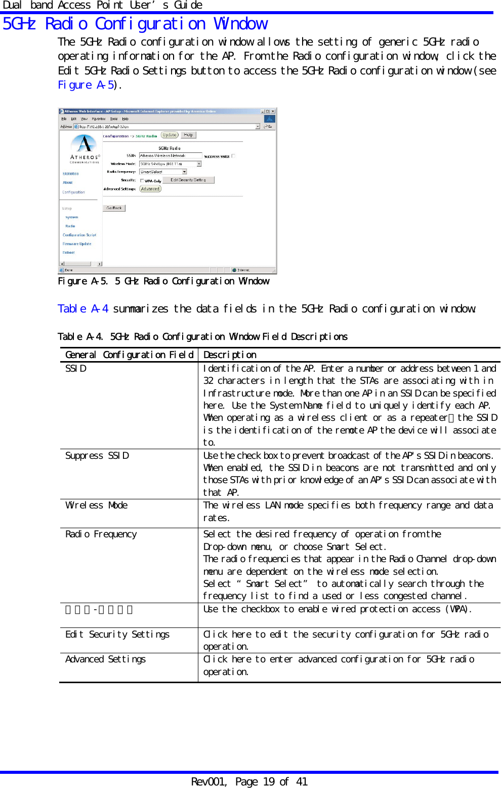
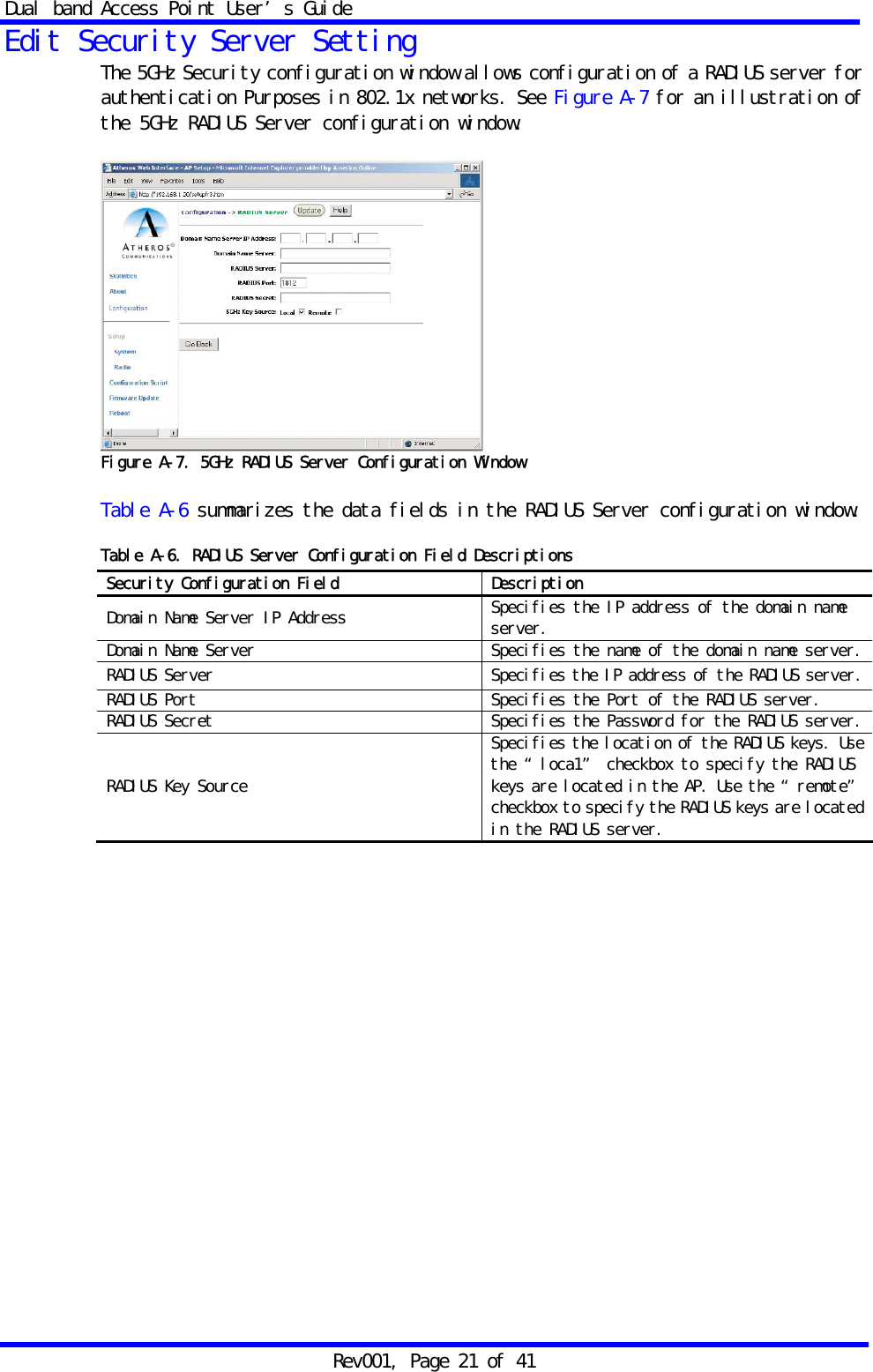
![Dual band Access Point User’s Guide Rev001, Page 23 of 41 5GHz 802.1X Configuration The IEEE 802.1X Protocol is designed to support Port-based authentication and secure key distribution, as well as unique encryption keys distribution for an entire BSS. Honda provides AP and STA support for this Protocol. To enable 802.1x on the AP, take the following steps on the 5GHz RADIUS Server configuration window (see Figure A-7): 1. Specify the domain name server IP address. 2. Specify the name of the domain server. 3. Specify a RADIUS Server name. 4. Specify a RADIUS Server secret. 5. Specify the location of the 5GHz Key Source as Remote. 6. Click the Update button. 7. After the last change to the AP, click the Reboot button to reboot the AP for the changes to take effect. Reminder: After making the last change, click [Reboot AP] button for changes to take effect.](https://usermanual.wiki/Honda-R-and-D/70410-QAB/User-Guide-666964-Page-23.png)