Honda R and D 70410-QAB Wireless Access Point User Manual
Honda R&D; Co., Ltd. Wireless Access Point Users Manual
Users Manual

Dual band Access Point User’s Guide
Rev001, Page 1 of 41
2.4GHz/5.2GHz Dual band
Wireless LAN Access Point
User's Guide
70410-QAB
Preliminary
Revision October 2005

Dual band Access Point User’s Guide
Rev001, Page 2 of 41
Warning
To prevent fire or shock hazard, do not expose the unit to rain or moisture.
To avoid electrical shock, do not open the cabinet. Refer servicing to qualified
personnel only.
CAUTION You are cautioned that any changes or modifications not expressly approved in this
manual could void your warranty.
FCCID: T4S-70410-QAB
Exposure to Radio Frequency Radiation.
The radiated output power of the Wireless LAN Access Point is far below the FCC radio
frequency exposure limit. Nevertheless, the wireless LAN Access Point shall be used
in such a manner that the potential for human contact during normal operation is
minimized.
Radio Frequency Interference Requirements
The operation of this device in the 5.15GHz to 5.25GHz frequency range is restricted
to indoor use. FCC regulations require this Product to be used indoors while
operating at 5.15GHzto5.25GHz to reduce the Potential for harmful interference.
However, the operation of this device in the 5.25GHz to 5.35GHz frequency range is
allowed for both indoor and outdoor use.
High Power radars are allocated as primary users of the 5.25GHz to 5.35GHz and 5.65GHz
to 5.85GHz bands. These radar stations can cause interference with and/or damage
to this device.
FCC Warning
This equipment has been tested and found to comply with the limits for a digital
device, pursuant to Part 15 of the FCC Rules. These limits are designed to provide
reasonable protection against harmful interference in a residential installation.
This equipment generates, uses, and can radiate radio frequency energy and, if not
installed and used in accordance with the instructions, may cause harmful
interference to radio communications. There is no guarantee that interference will
not occur in a particular installation. If this equipment does cause harmful
interference to radio or television reception, which can be determined by turning
the equipment off and on, the user is encouraged to try to correct the interference
by one or more of the following measures:
■ Reorient or relocate the radio/TV receiving antenna.
■ Increase the separation between the equipment and the radio/TV receiver.
■ Connect the equipment into an outlet on a circuit different from that to which
the radio/TV receiver is connected.
■ Consult the dealer or an experienced radio/TV technician for help.
Modifications made to the product, unless expressly approved by Honda R&D Co., Ltd.
could void the user's authority to operate the equipment.
FCC Radio Frequency Exposure Statement
This equipment generates and radiates radio-frequency energy. In order to comply
with FCC radio-frequency radiation exposure guidelines for an uncontrolled
environment, this equipment has to be installed and operated while maintaining a

Dual band Access Point User’s Guide
Rev001, Page 3 of 41
minimum body to antenna distance of 20cm. Based on continuous exposure of
30minutes.
Users are not permitted to make changes or modify the system in any way.
The number below is for FCC-related matters only.
To Comply with FCC RF exposure compliance requirement, this device must not be
co-located or operating in conjunction with any other antenna or transmitter.
The supplied interface cable must be used with the equipment in order to comply with
the limits for a digital device pursuant to Subpart B of Part 15 of FCC Rules.
The socket outlet shall be installed near the equipment and shall be easily
accessible.
NOTE: The power outlet should be installed near the equipment and should be easily
accessible.
European Community Declaration of Conformity with Regard to the R&TTE Directive 1999/5/EC
The following standards were applied: (Omni)
Radio: EN 300-328 v1.6.1 (2.4-GHz operation)
EN 301-893 v1.2.3 (5-GHz operation)
EMC: EN 301.489-1 v1.4.1, EN 301.489-17 v1.2.1
Safety: IEC 60950 ( 1999 3rd Edition with Amend. 1,2,3,4 ) & EN 60950 ( 2000 )
Note: This equipment is intended to be used in all EU and EFTA countries. Outdoor use
may be restricted to certain frequencies and/or may require a license for operation. For
more details, contact your customer service representative.
To comply with RF exposure compliance requirements, a separation distance of at least
20 cm must be maintained between the antenna of this device and all persons. This
device must not be co-located or operating in conjunction with any other antenna or
transmitter.
Member States shall ensure that the manufacturer or the person responsible for placing
the apparatus on the market provides information for the user on the intended use of the
apparatus, together with the declaration of conformity to the essential requirements.
Where it concerns radio equipment, such information shall be sufficient to identify on the
packaging and the instructions for use of the apparatus the Member States or the
geographical area within a Member State where the equipment is intended to be used
and shall alert the user by the marking on the apparatus referred to in Annex VII,
paragraph 5, to potential restrictions or requirements for authorization of use of the radio
equipment in certain Member States.
Declaration of Conformity
Trade Name: Honda R&D Co., Ltd.
Model No. : 70410-QAB
Responsible Party: TOKO, Inc.
Address: 18 Oaza Gomigaya Tsurugashimashi Saitama-ken 350-2281 JAPAN
Telephone: +81-49-279-1625
This phone number is for FCC-related matters only.
This device complies with part 15 of the FCC Rules.
Operation is subject to the following two conditions.
(1) This device may not cause harmful interference, and
(2) this device must accept any interference received, including interference
that may cause undesired operation.

Dual band Access Point User’s Guide
Rev001, Page 4 of 41
Declaration of Conformity with Regard to the R&TTE Directive 1999/5/EC
Česky
[Czech] HONDA tímto prohlašuje, že tento 70410-QAB je ve shodě se základními požadavky a dalšími
příslušnými ustanoveními směrnice 1999/5/ES.
Dansk
[Danish]
Undertegnede HONDA erklærer herved, at følgende udstyr 70410-QAB overholder de væsentlige krav
og øvrige relevante krav I direktiv 1999/5/EF.
Deutsch
[German]
Hiermit erklärt HONDA dass sich das Gerät 70410-QAB in Übereinstimmung mit den grundlegenden
Anforderungen und den übrigen einschlägigen Bestimmungen der Richtlinie 1999/5/EG befindet.
Eesti
[Estonian]
Käesolevaga kinnitab HONDA seadme 70410-QAB vastavust direktiivi 1999/5/EÜ põhinõuetele ja
nimetatud direktiivist tulenevatele teistele asjakohastele sätetele.
English Hereby, HONDA declares that this 70410-QAB is in compliance with the essential requirements and
other relevant provisions of Directive 1999/5/EC.
Español
[Spanish]
Por medio de la presente HONDA declara que el 70410-QAB cumple con los requisitos esenciales y
cualesquiera otras disposiciones aplicables o exigibles de la Directiva 1999/5/CE.
Ελληνική
[Greek]
ΜΕ ΤΗΝ ΠΑΡΟΥΣΑHONDA ∆ΗΛΩΝΕΙ ΟΤΙ70410-QAB ΣΥΜΜΟΡΦΩΝΕΤΑΙ ΠΡΟΣ ΤΙΣ ΟΥΣΙΩ∆ΕΙΣ
ΑΠΑΙΤΗΣΕΙΣ ΚΑΙ ΤΙΣ ΛΟΙΠΕΣ ΣΧΕΤΙΚΕΣ ∆ΙΑΤΑΞΕΙΣ ΤΗΣ Ο∆ΗΓΙΑΣ 1999/5/ΕΚ.
Français
[French]
Par la présente HONDA déclare que l'appareil 70410-QAB est conforme aux exigences essentielles et
aux autres dispositions pertinentes de la directive 1999/5/CE.
Italiano
[Italian]
Con la presente HONDA dichiara che questo 70410-QAB è conforme ai requisiti essenziali ed alle altre
disposizioni pertinenti stabilite dalla direttiva 1999/5/CE.
Latviski
[Latvian]
Ar šo HONDA deklarē, ka 70410-QAB atbilst Direktīvas 1999/5/EK būtiskajām prasībām un citiem ar to
saistītajiem noteikumiem.
Lietuvių
[Lithuanian]
Šiuo HONDA deklaruoja, kad šis 70410-QAB atitinka esminius reikalavimus ir kitas 1999/5/EB
Direktyvos nuostatas.
Nederlands
[Dutch]
Hierbij verklaart HONDA dat het toestel 70410-QAB in overeenstemming is met de essentiële eisen en
de andere relevante bepalingen van richtlijn 1999/5/EG.
Malti
[Maltese]
Hawnhekk, HONDA , jiddikjara li dan 70410-QAB) jikkonforma mal-ħtiġijiet essenzjali u ma
provvedimenti oħrajn relevanti li hemm fid-Dirrettiva 1999/5/EC.
Magyar
[Hungarian]
Alulírott, HONDA nyilatkozom, hogy a 70410-QAB megfelel a vonatkozó alapvetõ követelményeknek
és az 1999/5/EC irányelv egyéb elõírásainak.
Polski
[Polish]
Niniejszym, HONDA , deklaruję, że 70410-QAB spełnia wymagania zasadnicze oraz stosowne
postanowienia zawarte Dyrektywie 1999/5/EC.
Português
[Portuguese] HONDA declara que este 70410-QAB está conforme com os requisitos essenciais e outras
disposições da Directiva 1999/5/CE.
Slovensko
[Slovenian] HONDA izjavlja, da je ta 70410-QAB v skladu z bistvenimi zahtevami in ostalimi relevantnimi določili
direktive 1999/5/ES.
Slovensky
[Slovak] HONDA týmto vyhlasuje, že 70410-QAB spĺňa základné požiadavky a všetky príslušné ustanovenia
Smernice 1999/5/ES.
Suomi
[Finnish] HONDA vakuuttaa täten että 70410-QAB tyyppinen laite on direktiivin 1999/5/EY oleellisten
vaatimusten ja sitä koskevien direktiivin muiden ehtojen mukainen.
Svenska
[Swedish]
Härmed intygar HONDA att denna 70410-QAB står I överensstämmelse med de väsentliga
egenskapskrav och övriga relevanta bestämmelser som framgår av direktiv 1999/5/EG.

Dual band Access Point User’s Guide
Rev001, Page 5 of 41
電波に関するご注意
・ 本機器におけるIEEE02.11aでの通信は屋内に限られます。
・ IEEE802.11g/bで使用する周波数帯では、電子レンジ等の産業・科学・医療用機器のほか工場
の製造ライン等で使用されている移動体識別用の構内無線局(免許を要する無線局)及び特
定小電力無線局(免許を要しない無線局)が運用されています。
1. この機器を使用する前に、近くで移動体識別用の構内無線局及び特定小電力無線局が
運用されていないことを確認してください。
2. 万一、この機器から移動体識別用の構内無線局に対して電波干渉の事例が発生した場
合には、速やかに仕様周波数を変更するか、又は電波の発射を停止した上、弊社サポート
センターにご連絡頂き、混信回避のための処置等(例えば、パーティションの設置など)
についてご相談ください。
3. その他、この機器から移動体識別用の特定小電力無線局に対して電波干渉事例が発生
した場合など何かお困りのことが起きたときは、弊社サポートセンターへお問い合わせく
ださい。

Dual band Access Point User’s Guide
Rev001, Page 6 of 41
Safety information
WARNING ・Opening the unit, for whatever reason, could read to damages that are not covered
by the warranty.
・Do not touch the device or accessories during thunder storms. Electrical shock
could result.
・For indoor use only.
・Do not use this equipment on hospital premises. Doing so many cause medical devices
to malfunction.
・If using the equipment near a pacemaker, make sure it is at least 9inches (22cm)
away from the pacemaker.
・Do not use this equipment in an aircraft, as doing so could cause the aircraft
‘s equipment to malfunction.
・While using the Access Point, do not cover it or turn it on its side. Do not cover
the Access Point with objects such as magazines or newspapers or use it in confined,
enclosed places, such as the spaces between walls and furniture. Further, do not
turn the Access Point on its side while using it. Either situation could cause
heat to build up inside the Access Point, leading to overheating and possible fire.
・Carefully place the Ethernet cable, AC adapter, and other wire ring. Personal
injury or damage to the Access Point could result from people tripping over the
Ethernet cable, AC adapter, or power cord. Protect wiring by locating it in places
where people do not walk.
・Do not swing the AC adapter. Injury could result if the adapters strike a person
or fragile material, such as glass.
・Keep the Access Point out of the reach of children. Unforeseeable injury could
result from swallowing loose parts, etc.
・Place the Access Point on a stable surface. Do not place the Access Point on wobbly
or tilted surfaces. Tipping or falling could result injury.
・When using wall mounting, make sure that the wall is strong enough to support the
Access Point. The Access Point could fall if the wall is not strong enough,
leading to unforeseeable accidents. Further, be careful not to drop the unit or
the tools used for mounting it. Doing so could result in unforeseeable accidents.
・Avoid locations that are directly exposed to sunlight or heaters.
・Internal overheating could result in fire or damage to the unit.
・Make sure connectors are properly connected.
−Do not insert any metallic objects inside the connectors. Short-circuiting then
pins could cause fire or damage to the unit.
−Be careful to insert connectors squarely. Crooked insertion could cause pins to
short-circuit, possibly causing fire or damage to the unit.
・Use only the supplied AC adapter with Access Point. To disconnect Access Point
from the power supply, unplug the AC adapter.

Dual band Access Point User’s Guide
Rev001, Page 7 of 41
Precautions
AC Adapter
Use only supplied AC adapter. Other AC adapters may cause a failure in the Access Point.
Safety
Do not drop the Access Point. Careful handling will help prevent damage.
Installation
Do not place the Access Point where it will be exposed to the following conditions:
■ Unstable surface.
■ High humidity or poor ventilation.
■ Excessive dust.
■ Direct sunlight or extreme heat.
■ Closed cars.
■ Magnetized location (near magnet, speakers, or televisions).
■ Locations exposed to frequent vibration.
■ Locations where the transmission of radio waves may be obstructed by metal plates or
concrete walls.
Operation
Exposure to cold-to hot temperature extremes or very damp environments may cause moisture
to condense on internal parts. This may prevent the Access Point from operating properly.
If this should happen, unplug the AC adapter from the power outlet and let the Access Point
sit for two to three hours or until the moisture evaporates.
Cleaning
Clean the casing with a soft cloth lightly moistened with water or a mild detergent solution.
Do not use any type of abrasive pad, scouring powder or solvent such as alcohol or benzene.
This may damage the finish of the casing.

Dual band Access Point User’s Guide
Rev001, Page 8 of 41
Contents
Chapter1 introduction - Describes the Access Point package contents
and system requirements.
Chapter2 AP Network Attachment and Configuration - Describes the
Access Point network connections and initial software
configuration.
Appendix A AP Web Server - Describes the use of the web server to
configure the access point.

Dual band Access Point User’s Guide
Rev001, Page 9 of 41
1
Introduction
Package Contents
Once you have unpacked the units, make sure that all of the following items are
present.
■ Access Point (TMW1247)
■ AC Adaptor
■ Power Cable
■ External Antenna (TMM1262)
System Requirements
The AP contains a small boot executive that allows the main operating system software
to be downloaded using the Ethernet Port over an FTP connection. The operating system
software can also reside in the Flash memory of the AP, which allows booting without
the need to download the operating system from the host PC over an FTP connection.
A configuration file is created in Flash memory to store user-configurable
parameters such as wired equivalent Privacy (WEP) keys. A terminal or PC with an
Ethernet connection is required to perform the initial AP configuration. An FTP
server is required for firmware update to the AP.
WARNING: lf end users are allowed to upgrade firmware through the FTP server,confirm
that the End User License Agreement (EULA) covers upgrades to the firmware. The AP
upgrade code permits direct upgrades of the AP from the configuration screen if a
web browser is used. As a precaution, also use the EULA as the FTP startup text in
the event some end users log in to the FTP server manually.
Use the AP Web Server for firmware updates. Refer to ″AP Firmware Update
Configuration Window″ on Page A-33 for information on the web server.
Dual band Access Point User’s Guide
Rev001, Page 10 of 41
2
AP Network Attachment and
Configuration
This section provides procedures for connecting and configuring the access Point
(AP) to a host PC (HPC). Configuration can be performed either from a web browser
accessing the built-in web server or by entering commands using the command line
interface (CLI). For detailed information on using the web server, refer to “AP
Web Server Homepage” in Appendix A. For detailed information on using CLI, refer
to “AP Command-Line interface” in Appendix B. For “Factory Default Settings”
refer to Appendix B.
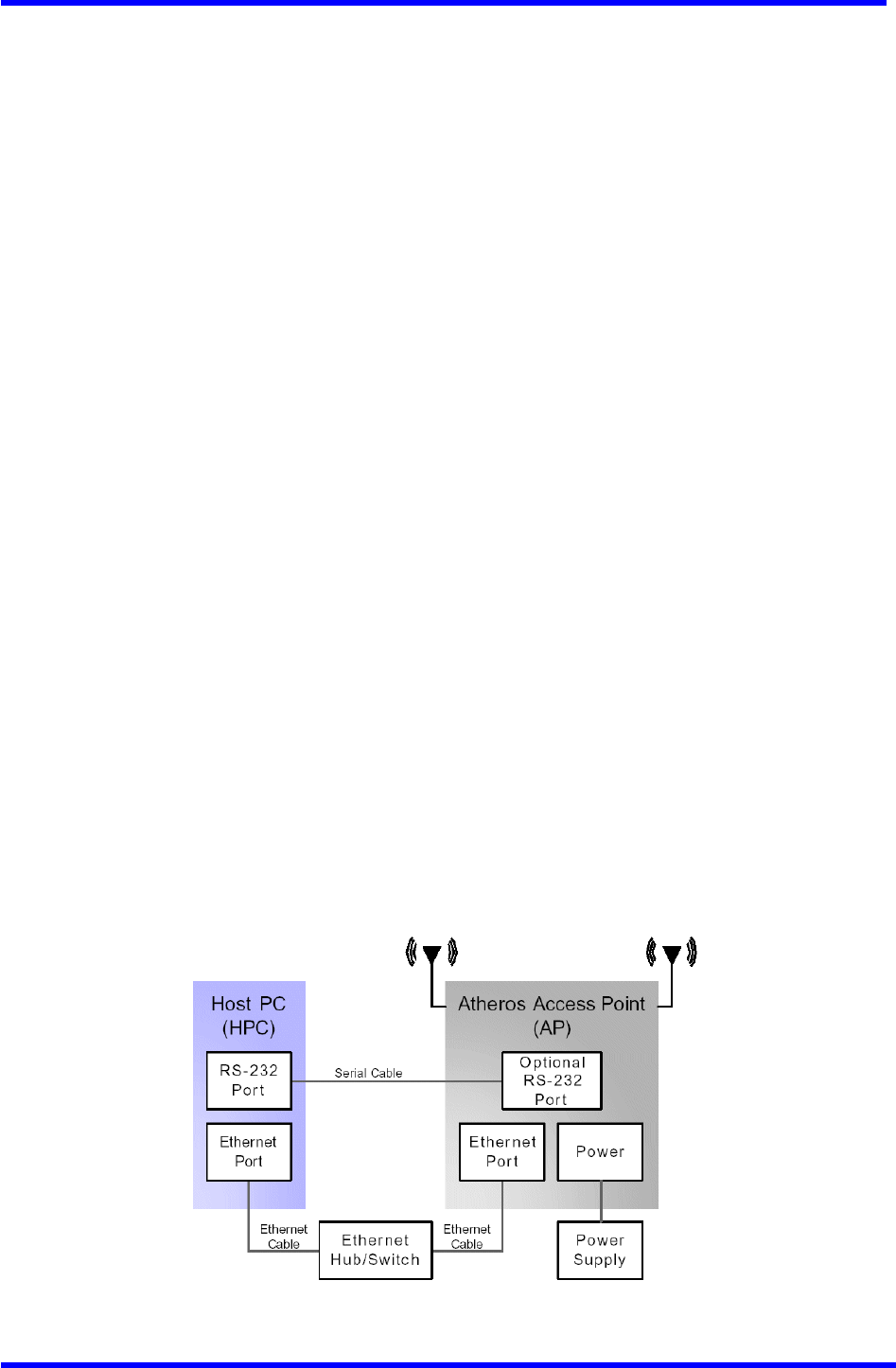
AP Network Connections
Connect the HPC to the AP using one of the following methods:
■ Use an Ethernet crossover cable (not supplied) to connect directly to the
Ethernet port of the HPC.
■ Use standard Ethernet cables (not supplied)to connect through a hub or Ethernet
switch.
See Fig11re 2-1 for an example of the AP to the HPC connections.
Follow these steps to establish the network connections:
1. Connect the AP Ethernet port to the HPC Ethernet card through the Ethernet
hub/switch or an Ethernet crossover cable.
2. Connect the optional RS-232 Port to the HPC seria1 Port through a serial cable.
Refer to Appendix C for more information on the serial interface.
3. Plug in the provided power supply to the AP power supply connector.
Figure 2-1. Access Point to HPC Connections
Dual band Access Point User’s Guide
Rev001, Page 11 of 41
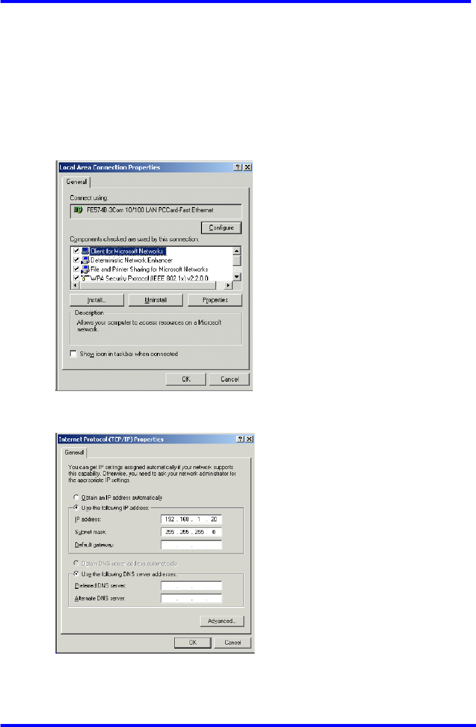
Network Configuration
To configure the HPC for AP network control:
1. From the HPC’s Start menu, choose Settings and open the Network and
Dial-up Connections dialog box.
2. Right-click on the Local Area Connection icon that belongs to the Ethernet
controller connected to the AP, and select Properties.
3. Within the Local Area Connection Properties dialog box, choose Internet
Protocol (TCP/IP) and click Properties.
4. Configure the IP address for the Ethernet connection in the Internet
Protocol (TCP/IP) Properties dialog box.
5. Click OK to continue and close the Internet Protoco1 Properties dialog box.
Dual band Access Point User’s Guide
Rev001, Page 12 of 41
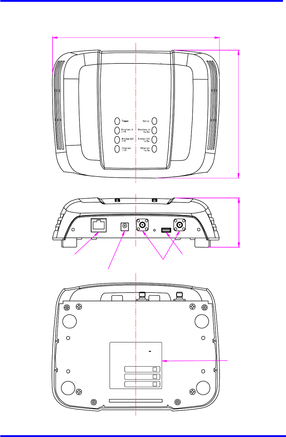
AP Hardware Configuration
This section describes AP hardware configuration. Figure 2-2 shows the Honda AP
70410-QAB. Table 2-l describes the AP LEDs.
Figure 2-2. Honda Access Point 70410-QAB
139 max.
182 max.
55 max.
SMA Connector for
External Antenna
Ethernet Connector
DC Jack
RS232C Connector
FCC Label
00305BXXXXXX
00305BXXXXXX
00305BXXXXXX
MAC ADDRESS
MAC ADDRESS
MAC ADDRESS
TRADE NAME: Wireless Access Point
Model Name: 70410-QAB
IC : XXXX-70410-QAB
FCC ID : T4S-70410-QAB
This device complies with P art 15 of the FCC R ules. Operation is subject to
following two conditions:(1) this device may not cause harmful inte r ference.
and (2) this device must accept any inte r ference received, including
inte rference that may cause undesired operation .
802.11b/g
802.11a
Ethernet
HONDA R&D Co.,Ltd.
MADE IN JAPAN
Power: 5VDC ,2A max.
Dual band Access Point User’s Guide
Rev001, Page 13 of 41
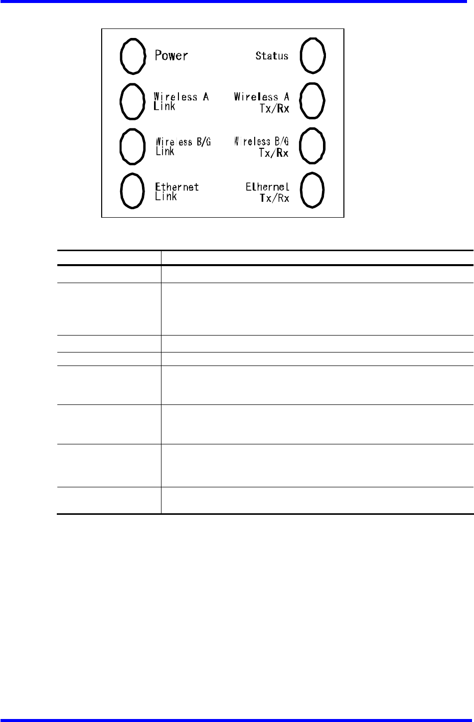
Table 2-1. Access Point LED Descriptions
LED Name Description
Power This LED always remains on during power on of AP.
Status
This LED indicates several AP status.
Green: Indicates no error
Orange: Indicates firmware updating
Red: Indicates Error
Wireless A Link This LED remains on when ready for 802.11a traffic.
Wireless A Tx/Rx This LED remains on during 802.11a traffic.
Wireless B/G Link This LED remains on when ready for 802.11b/g traffic.
Green indicates 802.11g link.
Orange indicates 802.11b link.
Wireless B/G Tx/Rx This LED remains on during 802.11b/g traffic.
Green indicates 802.11g traffic.
Orange indicates 802.11b traffic.
Ethernet Link This LED remains on when ready for Ethernet traffic.
Green: 100Base link ready
Orange: 10Base link ready
Ethernet Tx/Rx This LED remains on when a LAN connection is live to the AP. Orange
indicates collision.

Dual band Access Point User’s Guide
Rev001, Page 14 of 41
AP Initial Configuration
Configure the AP after booting from Flash memory. Refer to “Firmware Update
Configuration window” on Page A-33 for information on loading the operating image
file to the Flash file system, if the operating system software needs updating.
Configure the AP for its channel frequency and service set identifier (SSID) unique
to the application. This configuration can be done through a web browser with access
to the built-in AP web server. The AP can be configured at any time to tailor it
for the application environment.
For more information on configuring the AP using the web browser, refer to “AP Web
Server” in Appendix A.
The following description illustrates the use of the web browser.
Dual band Access Point User’s Guide
Rev001, Page 15 of 41
A
AP Web Server
Configure the Access Point (AP) either through a web browser interfaces to the AP
web server. The web server resides in the AP and is accessible from any station (STA)
that is connected to the AP infrastructure network.
This appendix describes configuring the AP through the AP Web Server.
Accessing the AP Web Server
To access the AP Web Server:
1. Launch a web browser. Netscape Navigator and Internet Explorer are examples
of commonly used web browsers.
2. From the HPC, enter the IP address that is assigned to the AP as the URL address.
For example, the default address is http://192.168.1.20.
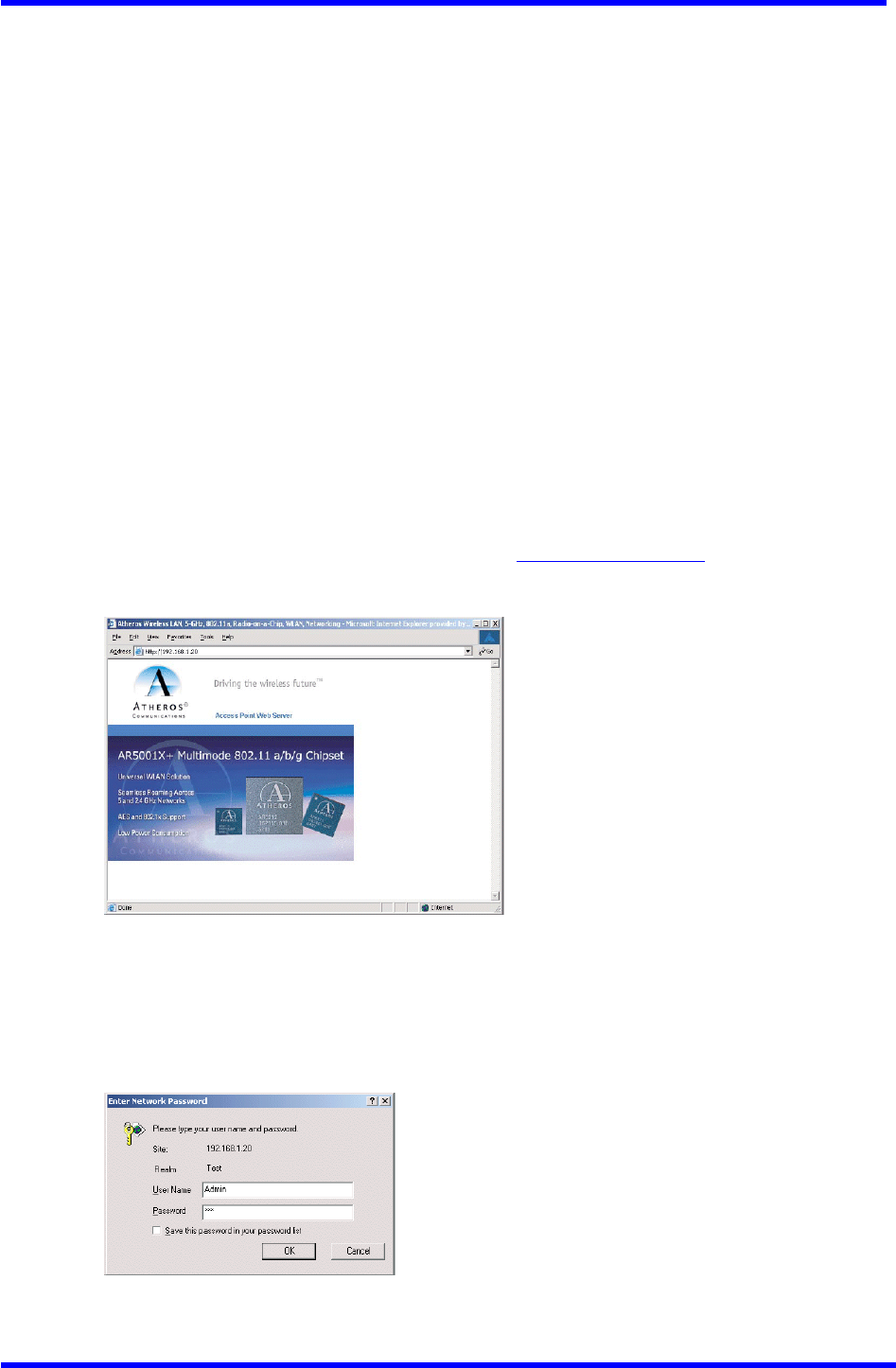
The Access Point Web Server homepage appears (see Figure A-1).
Figure A-1. AP Web Server Homepage
3. Click on the image to access the configuration pages.
4. A dialog box appears requesting login authorization.
User Name : Admin (case sensitive)
Password : 5up
5. Click OK to complete the login Process.

Dual band Access Point User’s Guide
Rev001, Page 16 of 41
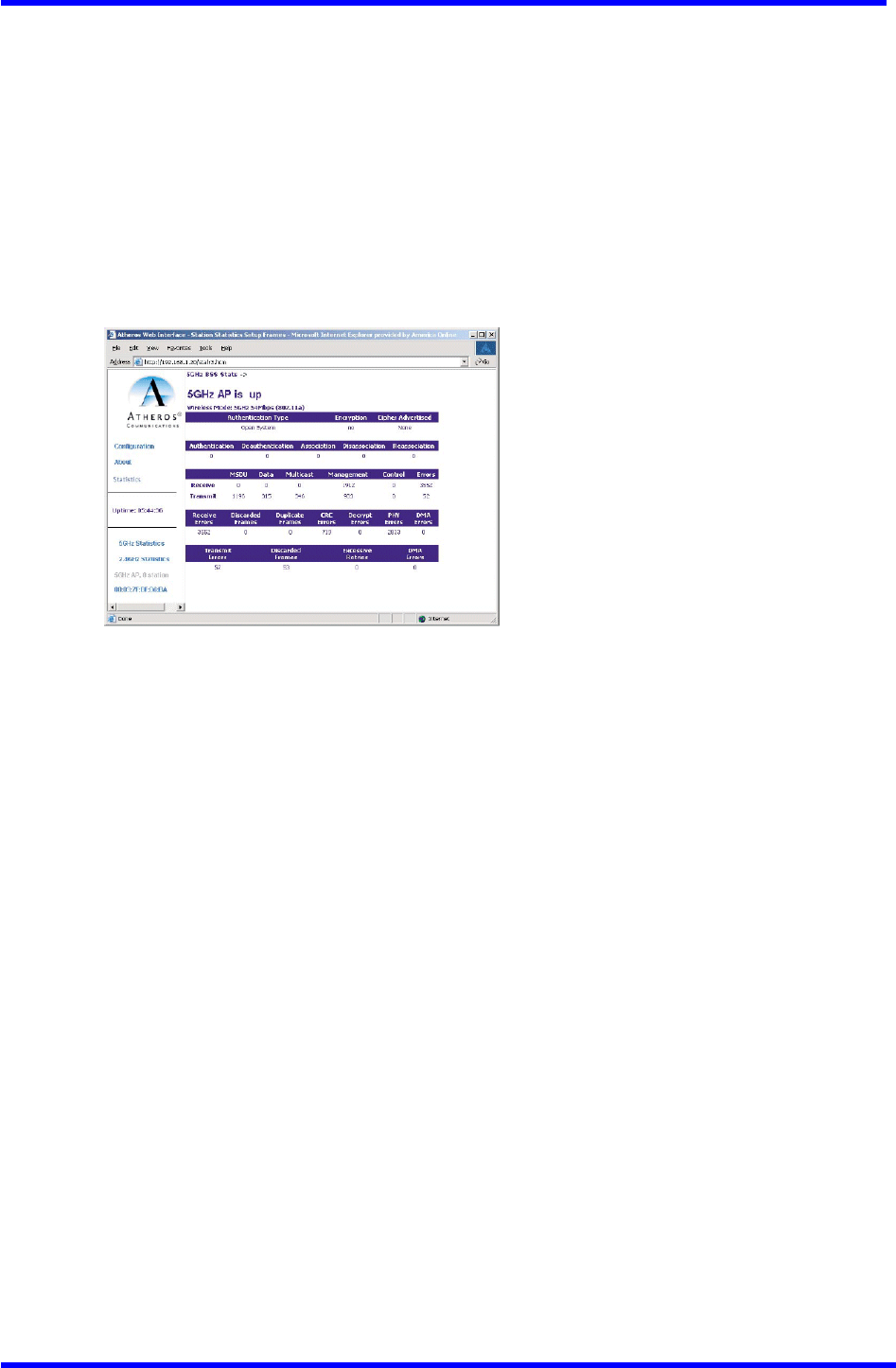
NOTE: the web browser must support frames and Java script must be enabled.
The Access Point Web Server 5GHz Statistics window appears (see Figure A-2).
Figure A-2. 5 GHz Statistics Window
Configuration Windows
The web server configuration windows allow viewing and editing of configuration
information for the AP. The web server Provides configuration windows for:
■ System configuration Parameters
■ 5GHz and 2.4 GHz radio configuration Parameters
■ 5GHz and 2.4 GHz statistics
■ Security
■ Configuration scripts
■ Firmware updates
To access any of these AP configuration screens, click on the desired hotlink from
the navigation bar on any configuration screen.
Working with Configuration Windows
The Web Server configuration windows provide a user-friendly interface to aid in
quick configuration of the AP. After making any additions or changes to any
configuration window, update the configuration file to save the changes. The new
configuration is not in effect until the AP reboots.
To update configuration files:
1. Enter the configuration updates or changes in the appropriate configuration
fields.
2. Click the Update button.
3. Click Reboot to reboot the AP and make the changes effective.
The web server loses connectivity with the Web Server as the AP reboots. To
reestablish the connection with the Web Server, wait until the AP has completed
rebooting, then navigate to the Web Server.
Dual band Access Point User’s Guide
Rev001, Page 17 of 41
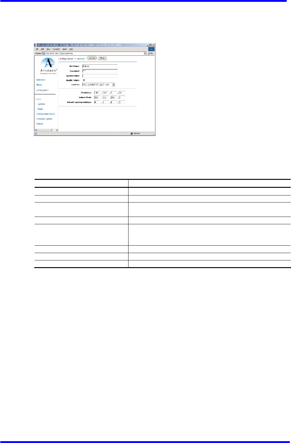
System Configuration Window
The System configuration window allows the setting of general operating information
for the AP. Click on Configuration from any window to access the system configuration
window (see Figure A-3).
Figure A-3. AP System Configuration Window
Table A-2 summarizes the data fields in the System configuration window.
Table A-2. System Configuration Window Field Descriptions
General Configuration Field Description
User Name Specifies the user name.
Password Specifies the Password.
System Name Specifies a unique name for AP. Enter a unique text string
of up to 32 characters in length.
Enable Telnet Use the check box to allow teleneting into the AP.
Country Specifies the country where the AP is operating. Use the
drop-down menu to specify the country where the equipment
will operate from.
IP Address Specifies the IP address of the AP.
Subnet Mask Specifies the subnet mask for the AP.
Default Gateway Address Specifies the default gateway for the AP.
Dual band Access Point User’s Guide
Rev001, Page 18 of 41
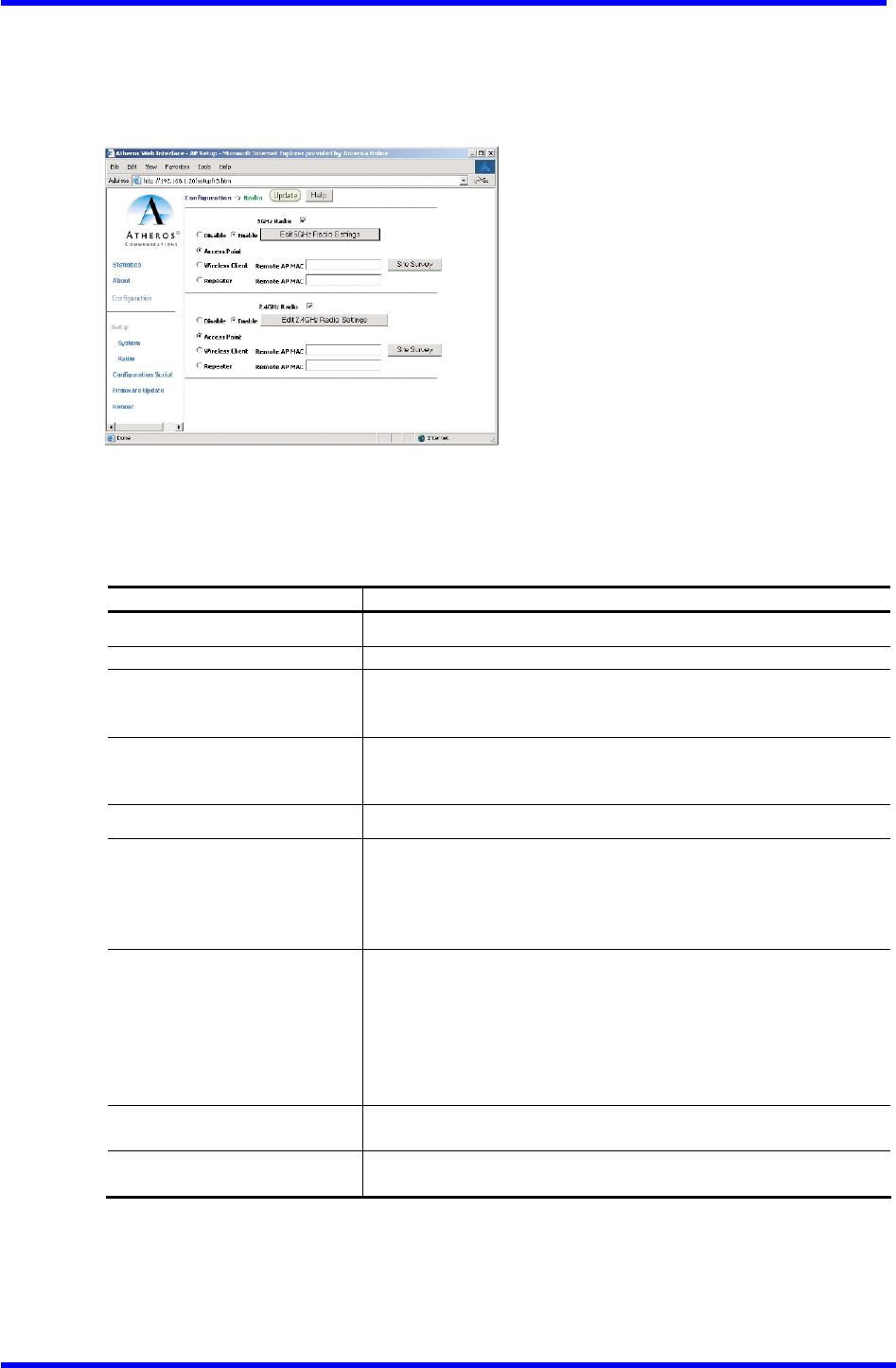
Radio Configuration Window
The Radio configuration windows allow the setting of generic radio operating
information for the AP. From the AP System configuration window, click Radio (see
Figure A-4).
Figure A-4. Radio Configuration Window
Table A-3 summarizes the data fields in the System configuration window.
Table A-3. Radio Configuration Window Field Descriptions
General Configuration Field Description
5GHz Radio Use the radio buttons to enable/disable 5GHz radio operation.
2.4GHz Radio Use the radio buttons to enable/disable 2.4GHz radio operation.
Edit 5GHz Radio Settings Click this button to edit the configuration for 5GHz radio
operation (refer to“5GHz Radio Configuration Window” on Page
A-8).
Edit2.4 GHz Radio Settings Click this button to edit the configuration for 2.4GHz radio
operation (refer to“2、4GHz Radio Configuration Window” on Page
A-21).
Access Point Use the radio button to select to use the Access Point.
Wireless Client Use the radio button to select to use the wireless client. Fill
in the Remote AP MAC address.
Wireless Client mode Provides wireless access for devices to
a remote AP. No STA can associate to the device when the device
is in wireless client mode.
Repeater Use the radio button to select to use a repeater. Fill in the
Remote AP MAC address.
The wireless repeater relays signals between STAs and an AP.
When an AP is in repeater mode, it scans for a root AP. 0nce
associated with a root AP, the repeater acts like a point-to
point bridge between clients associated with the repeater and
the root AP.
Remote AP MAC Fill in the MAC address of the remote AP when using a wireless
client or a repeater.
Site Survey Click the Site Survey button to run a 5GHz or 2.4 GHz site survey.
The site survey displays a list of every available AP.
Dual band Access Point User’s Guide
Rev001, Page 19 of 41
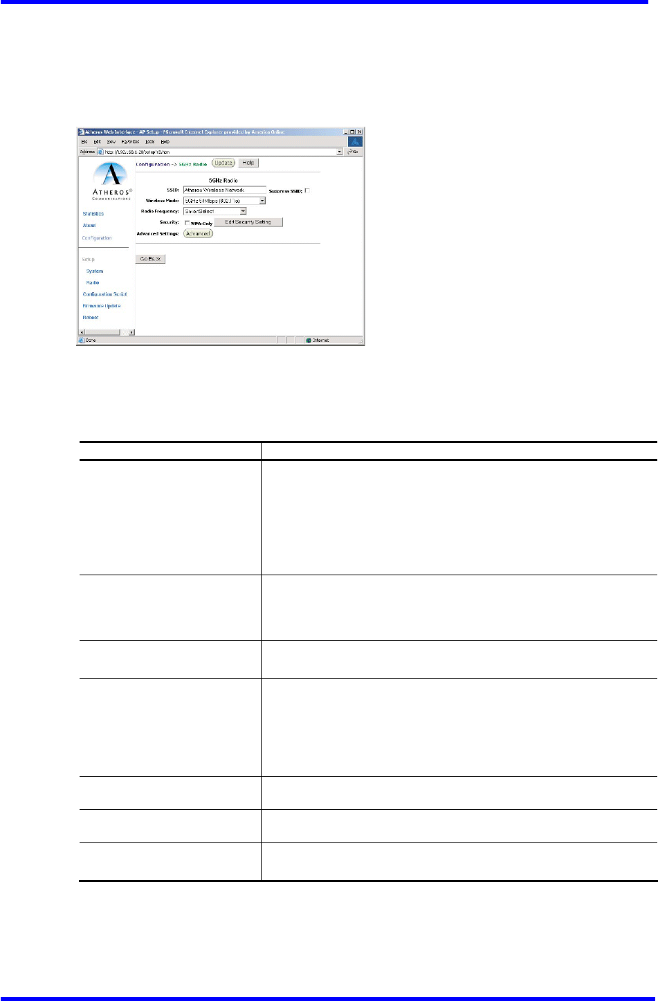
5GHz Radio Configuration Window
The 5GHz Radio configuration window allows the setting of generic 5GHz radio
operating information for the AP. From the Radio configuration window, click the
Edit 5GHz Radio Settings button to access the 5GHz Radio configuration window (see
Figure A-5).
Figure A-5. 5 GHz Radio Configuration Window
Table A-4 summarizes the data fields in the 5GHz Radio configuration window.
Table A-4. 5GHz Radio Configuration Window Field Descriptions
General Configuration Field Description
SSID Identification of the AP. Enter a number or address between 1 and
32 characters in length that the STAs are associating with in
Infrastructure mode. More than one AP in an SSID can be specified
here. Use the System Name field to uniquely identify each AP.
When operating as a wireless client or as a repeater,the SSID
is the identification of the remote AP the device will associate
to.
Suppress SSID
Use the check box to prevent broadcast of the AP's SSID in beacons.
When enabled, the SSID in beacons are not transmitted and only
those STAs with prior knowledge of an AP's SSID can associate with
that AP.
Wireless Mode
The wireless LAN mode specifies both frequency range and data
rates.
Radio Frequency
Select the desired frequency of operation from the
Drop-down menu, or choose Smart Select.
The radio frequencies that appear in the Radio Channel drop-down
menu are dependent on the wireless mode selection.
Select “Smart Select” to automatically search through the
frequency list to find a used or less congested channel.
WPA-Only
Use the checkbox to enable wired protection access (WPA).
Edit Security Settings
Click here to edit the security configuration for 5GHz radio
operation.
Advanced Settings
Click here to enter advanced configuration for 5GHz radio
operation.
Dual band Access Point User’s Guide
Rev001, Page 20 of 41
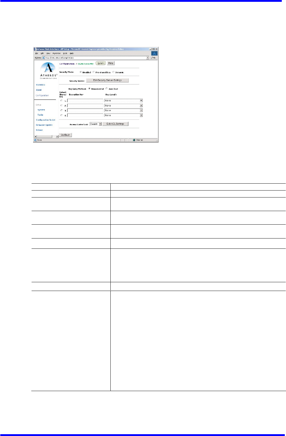
5GHz Security Configuration Window
The 5GHz Security configuration window allows the setting of security information
for the AP for 5GHz operation. From the 5GHz Radio configuration window, make sure
that WPA-only is not checked, then click on Edit Security Settings to access the
5GHz Security configuration window (see Figure A-6)・
Figure A-6. 5 GHZ Security Configuration Window
Table A-5 summarizes the data fields in the 5GHz Security configuration window.
Table A-5. 5GHz Security Field Descriptions
Security Configuration Field Description
Security Mode Use the radio buttons to specify the security mode.
Security Server Click Edit Security Server Settings to change the configuration of the
security server.
Key Entry Method Use the radio buttons to specify the key entry method as either
hexadecimal or ASCII.
Default Shared Key Use the radio button to specify which encryption key to use as the
default shared key・
Encryption Key Specifies the encryption key used for broadcast /multicast frames.
Key Length Specifies the key length:
■ None
■ 10 Hex digits or 5 ASCII text
■ 26 Hex digits or 13 ASCII text
■ 32 Hex digits or 16 ASCII text
Edit ACL settings Click here to edit the configuration of the ACL operation for 5GHz.
Access Control List Specifies the state of the access control list (ACL). Use the
drop-down menu to specify the state of ACL:
■ Disable - Unrestricted Access: By default, while checking of
the ACL is enabled, the access control list itself is empty.
This is the same as disabling the checking on the ACL.
■ Enable - Restricted Access: An ACL entry must exist before ACL
can be enabled. While ACL is enabled,stations with valid
shared keys and stations with matching “allow” entries on
the ACL are authenticated.
■ Strict - Restricted(w/ACL match): Requires an ACL entry that
specifies the station's assigned unique key or the station
is denied association. In the strict mode, stations with
valid share keys and not on the ACL are not authenticated.
The stations must have unique keys defined and matching
“allow” ACL entries specified to associate with the AP.
Dual band Access Point User’s Guide
Rev001, Page 21 of 41
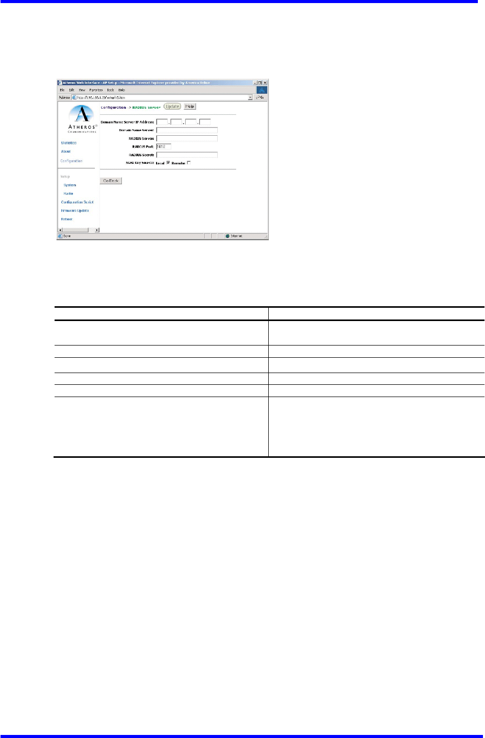
Edit Security Server Setting
The 5GHz Security configuration window allows configuration of a RADIUS server for
authentication Purposes in 802.1x networks. See Figure A-7 for an illustration of
the 5GHz RADIUS Server configuration window.
Figure A-7. 5GHz RADIUS Server Configuration Window
Table A-6 summarizes the data fields in the RADIUS Server configuration window.
Table A-6. RADIUS Server Configuration Field Descriptions
Security Configuration Field Description
Domain Name Server IP Address Specifies the IP address of the domain name
server.
Domain Name Server Specifies the name of the domain name server.
RADIUS Server Specifies the IP address of the RADIUS server.
RADIUS Port Specifies the Port of the RADIUS server.
RADIUS Secret Specifies the Password for the RADIUS server.
RADIUS Key Source
Specifies the location of the RADIUS keys. Use
the “loca1” checkbox to specify the RADIUS
keys are located in the AP. Use the “remote”
checkbox to specify the RADIUS keys are located
in the RADIUS server.
Dual band Access Point User’s Guide
Rev001, Page 22 of 41
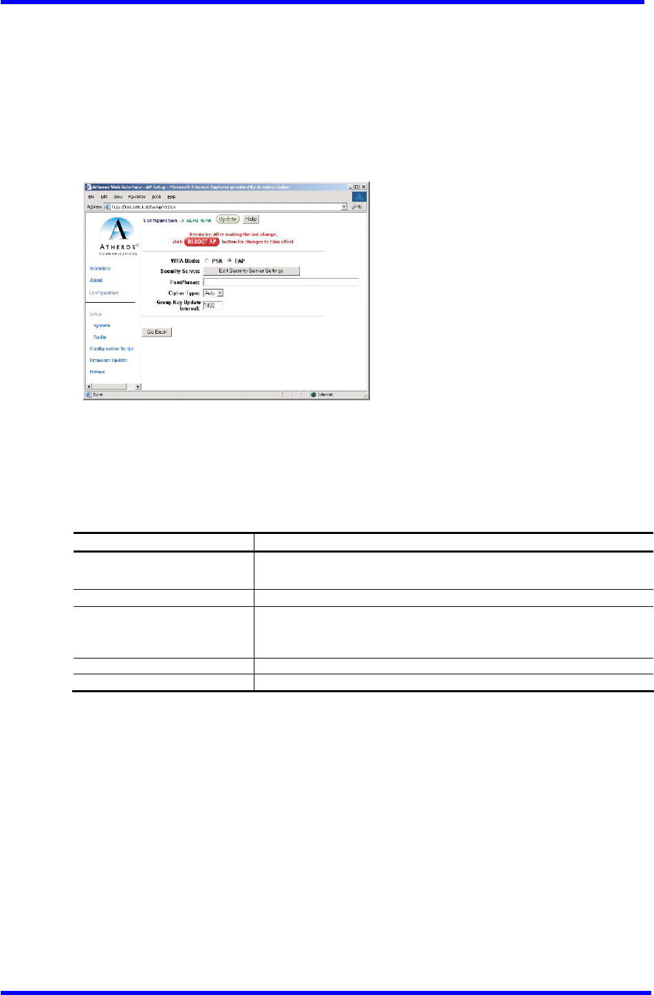
WPA Configuration
The 5GHz Security configuration window allows the setting of security information
for the AP for WPA-only operation.
To configure WPA on the AP using the web interface:
1. In the 5GHz Radio configuration window, check WPA-Only.
2. Click the Edit Security Settings button to access the 5GHz WPA configuration
screen.
Figure A-8. 5GHz WPA Configuration Screen
3. Click Edit Security Server Settings.
Table A-7 summarizes the data WPA Security configuration fields.
Table A-7. WPA Security Field Descriptions
4. Edit the security settings.
Choose EAP for WPA-TLS, or PSK for WPA-PSK authentication.
- If using WPA-PSK, enter a Pass Phrase.
- If using WPA-TLS, c1ick “Edit Security Server Settings” to enter RADIUS
server information (see Figure A-7). See Table A-6 for RADIUS Server
configuration field descriptions.
5. Click the Update button.
6. After the last change to the AR dick the Reboot button to reboot the AP for
the changes to take effect.
7. Use a STA to connect to the AP.
WPA_OnLy Field Description
WPA Mode Use the radio button to specify either PSK (Pre-Shred Key) or EAP
(802.1x).
Security Server Click here to enter RADIUS server information.
Pass Phrase Enter a Password phrase. Phrases can be 8-63 characters long and
can use any ASCII character. A hexadecimal Phrase must be exactly
64 characters.
Cipher Type Specify either TKIP, AES, or Auto.
Group Key Update Interval O=Disable. Enter an interval value of 15-300 sec.

Dual band Access Point User’s Guide
Rev001, Page 23 of 41
5GHz 802.1X Configuration
The IEEE 802.1X Protocol is designed to support Port-based authentication and secure
key distribution, as well as unique encryption keys distribution for an entire BSS.
Honda provides AP and STA support for this Protocol.
To enable 802.1x on the AP, take the following steps on the 5GHz RADIUS Server
configuration window (see Figure A-7):
1. Specify the domain name server IP address.
2. Specify the name of the domain server.
3. Specify a RADIUS Server name.
4. Specify a RADIUS Server secret.
5. Specify the location of the 5GHz Key Source as Remote.
6. Click the Update button.
7. After the last change to the AP, click the Reboot button to reboot the AP for
the changes to take effect.
Reminder: After making the last change,
click [Reboot AP] button for changes to take effect.

Dual band Access Point User’s Guide
Rev001, Page 24 of 41
5GHz Access Control List Configuration Window
The 5GHz Radio configuration window allows AP security information setting. From
the 5GHz Security configuration window, click Edit ACL Settings to access the 5GHz
ACL configuration window (see Figure A-9)
Figure A-9. 5 GHz ACL Configuration Window
Click Delete to remove any list item.
Dual band Access Point User’s Guide
Rev001, Page 25 of 41
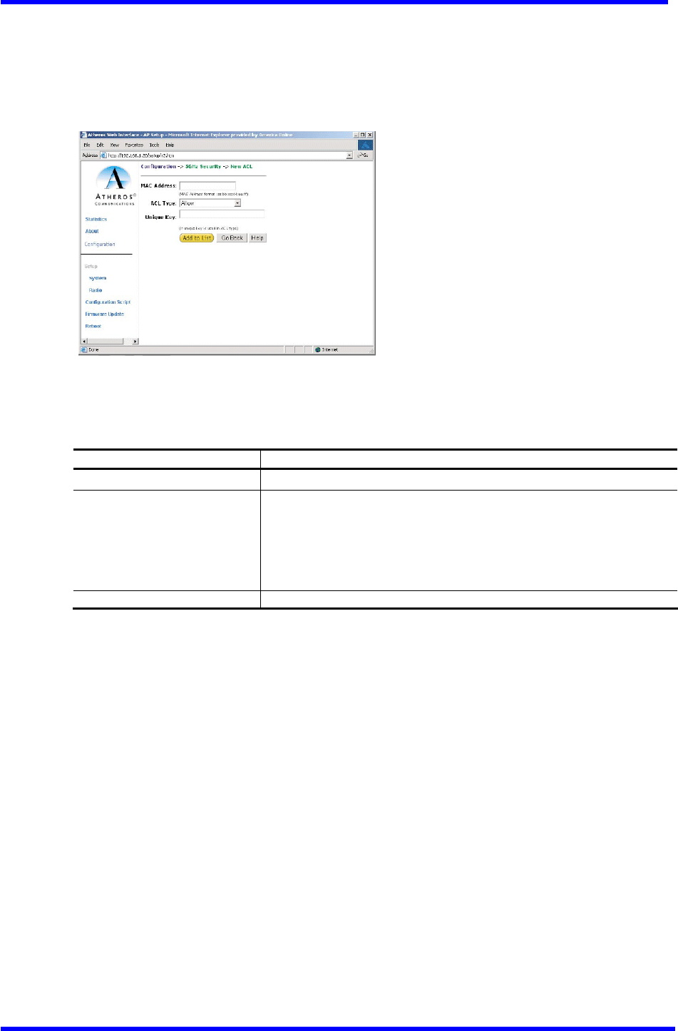
Adding New Access Control List
The 5GHz Security New ACL configuration window allows the addition of new access
control list items. From the 5GHz ACL configuration window, click Add to list to
enter new list items (see Figure A-10). Note that to access the ACL, the box next
to WPA-Only must be unchecked.
Figure A-10. 5 GHz New ACL Configuration Window
Table A-8 summarizes the data fields in the New ACL configuration window.
Table A-8. 5 GHz New Access Control List Field Descriptions
To add new items to the access control list (ACL):
1. Specify the ACL type from the drop-down menu.
The access control list (ACL) allows an administrator to perform security
actions based on the client station MAC address. Use this selection to
allow or deny association with the AP and for unique per station WEP key
assignment.
2. Enter the MAC address for the STA to be included on the access list.
3. Enter a unique key for the new list item.
4. Click Add to List.
Once entered in the ACL Contro1 List, click on Delete to remove any configured
STA from the access list.
5. Click the Update button.
6. After the last change to the AP, click the Reboot button to reboot the AP for
the changes to take effect.
Per Station Privacy Field Description
MAC Address Specifies the MAC address for the STA to be included in the ACL.
ACL Type
Specifies the current state of each STA:
■ Allow ‐ Enable access for this MAC address to the ACL.
■ Deny ‐ Deny access for this MAC address to the ACL.
■ Default Shared Key - This MAC address would use the default
shared key.
■ 64/128/152Bits - Specifies lengths for shared keys.
Unique Key Enter a unique key.
Dual band Access Point User’s Guide
Rev001, Page 26 of 41
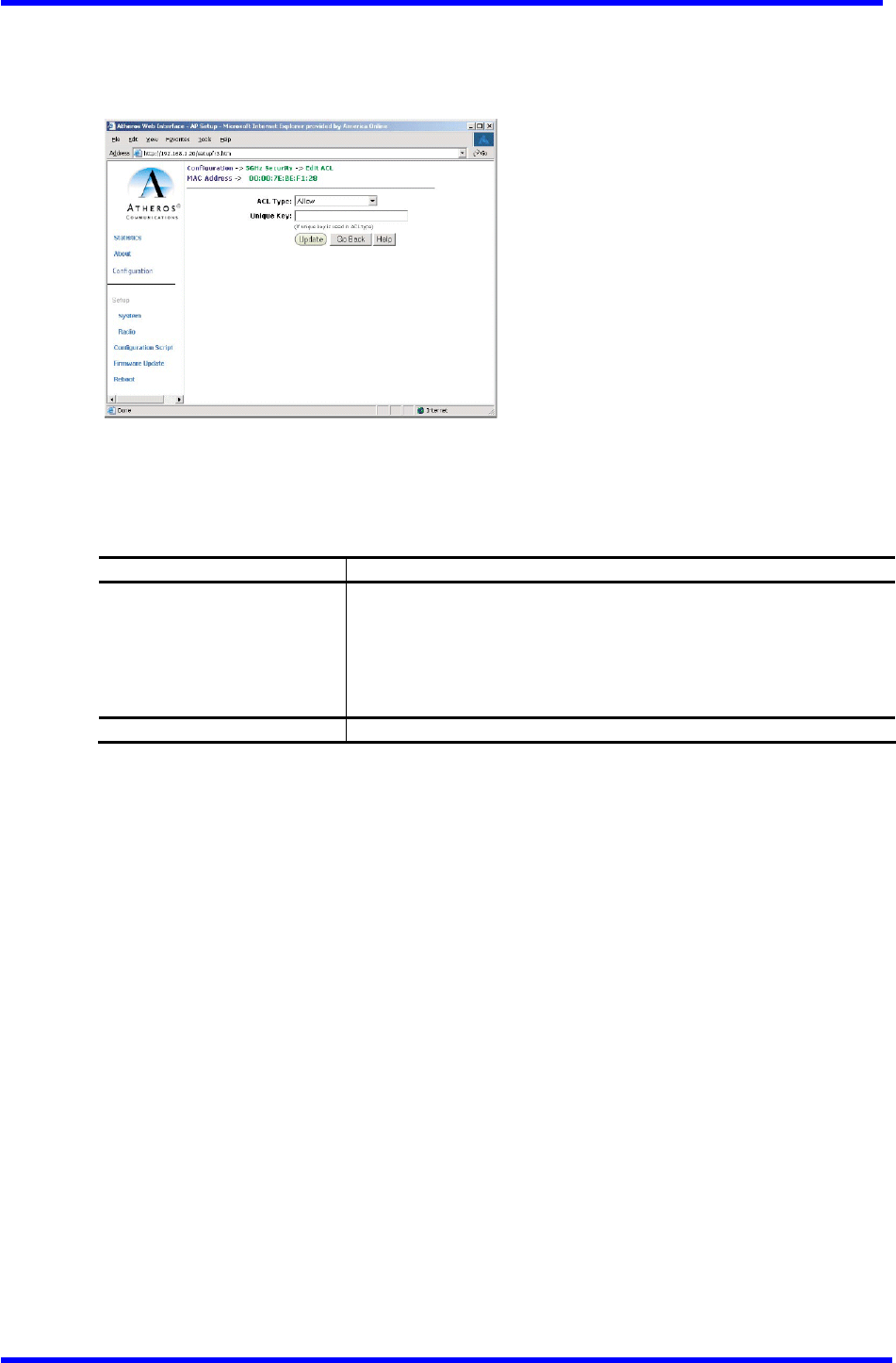
Adding Access Control List Permissions
The 5GHz ACL configuration window allows the addition of Permissions for each list
item. From the 5 GHz ACL configuration window, click on a MAC address in the list
to view the 5GHz Security Edit ACL configuration window (see Figure A-11).
Figure A-11. 5GHz Security Edit ACL Configuration Window
Table A-9 summarizes the data fields in the 5GHz Security Edit ACL window.
Table A-9. 5GHz Security Edit Access Control List Field Descriptions
Per Station Privacy Field Description
ACL Type
Specifies the current state of each STA:
■ A11ow - Enable access for this MAC address to the ACL.
■ Deny ‐ Deny access for this MAC address to the ACL.
■ Default Shared Key ‐ Use the default shared key for this MAC
address.
■ 64/128/152Bits - Specifies lengths for shared keys.
Unique Key Enter a unique key.
Dual band Access Point User’s Guide
Rev001, Page 27 of 41
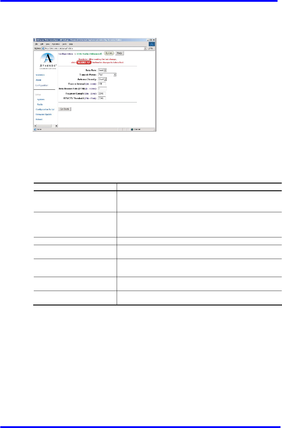
5GHz Radio Advanced Configuration Window
The 5GHz Radio (Advanced) configuration window allows the setting of advanced AP
5GHz radio operating information. From the 5GHz Radio configuration window, click
Advanced to access the 5GHz Radio (Advanced) configuration window (see Figure A-12).
Figure A-12. 5GHz Radio (Advanced) Configuration Window
Table A-10 summarizes the data fields in the 5 GHz Radio (Advanced) configuration
window.
Table A-10. 5GHz Radio Advanced Configuration Window Field Descriptions
Advanced Configuration Field Description
Data Rate Specifies data transmission rate. Select the desired rate from
the drop-down menu. The Best selection adapts the rate to best
available.
Transmit Power Specifies the level of transmit Power Choose the value from the
drop-down menu. Decrease the transmit Power if more than one
AP is co-located using the same channel frequency.
Antenna Diversity Specifies which antennae to use: Best, 1, or 2.
Beacon Interval Specifies the beacon interval value. Enter a value between 20
and 1000.
Data Beacon Rate Specifies the Data Beacon Rate. Enter a value between 1 and 16384
that specifies the delivery traffic indication message (DTIM).
Fragment Length Specifies the fragment length. Enter a value between 256 and
2346.
RTS/CTS Threshold Specifies the value of the RTS/CTS threshold. Enter a value
between 256 and 2346.

Dual band Access Point User’s Guide
Rev001, Page 28 of 41
2.4GHz Radio Configuration Window
The 2.4 GHz Radio configuration window allows the setting of generic 2.4GHz radio
operating information for the AP. From the Radio configuration window (see Figure
A-4), click on Edit 2.4 GHz Radio Settings to access the 2.4GHz Radio configuration
window (see Figure A-13).
Figure A-13. 2.4GHz Radio Configuration Window
Table A-11 summarizes the data fields in the 2.4GHz Radio configuration window.
Table A-11. 2.4GHz Radio Configuration Window Field Descriptions
General Configuration Field Description
SSID Identification of the AP. Enter a number or address between
1 and 32 characters in length that the STAs are associating
with in Infrastructure mode. More than one AP in an SSID can
be specified here. Use the System Name field to uniquely
identify each AP.
Suppress SSID
Use the check box to prevent broadcast of the AP's SSID in
beacons. When enabled, the SSID in beacons are not transmitted
and only those STAs with Prior knowledge of an AP's SSID can
associate with that AP.
Wireless Mode
The wireless LAN mode specifies both frequency range and data
rates.
Radio Frequency Select the desired frequency of operation from the drop-down
menu, or choose Smart Select. The radio frequencies that
appear in the Radio Channel drop-down menu are dependent on
the wireless mode selection. Select “Smart Select” to
automatically search through the frequency list to find a used
or less-congested channel.
WPA-Only Use the check box to enable WPA.
Edit Security Settings Click here to edit the security configuration for 2.4GHz radio
operation (refer to“Edit Security
Server Settings” on page A-12).
Advanced Settings Click here to enter advanced configuration settings for
2.4GHz radio operation (refer to “2.4GHz Radio Advanced
Configuration Window” on page A-30).
Dual band Access Point User’s Guide
Rev001, Page 29 of 41
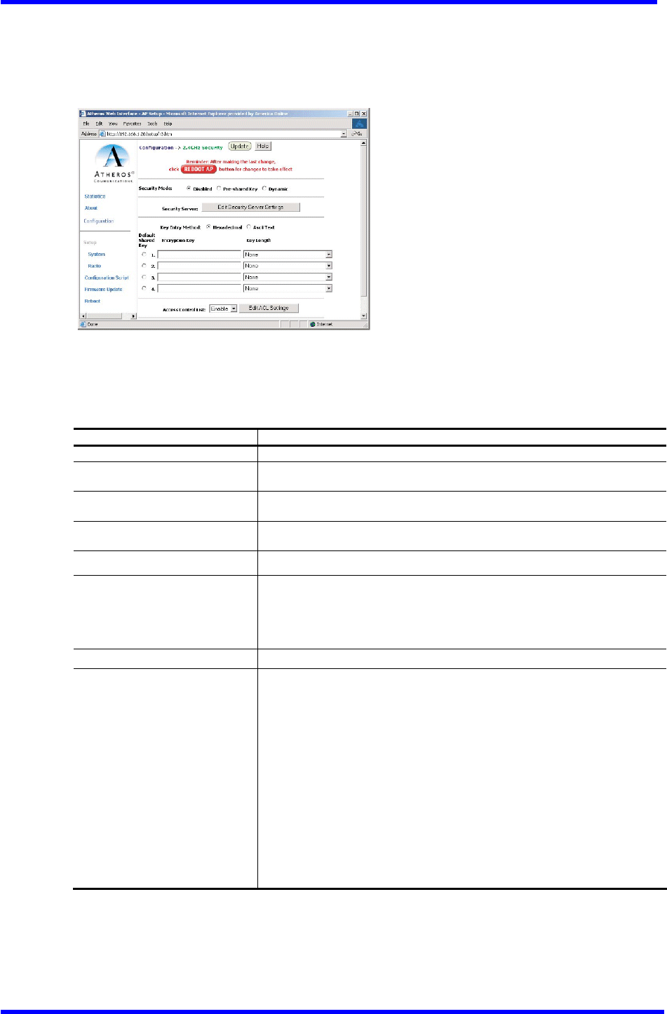
2.4 GHz Security Configuration Window
The 2.4 GHz Radio Security configuration window allows the setting of security
information for the AP for 2.4 GHz operation. From the 2.4GHz Radio configuration
window, make sure that WPA-only is not checked, then click on Edit Security Settings
to access the 2.4 GHz Security configuration window (see Figure A-14).
Figure A-14. 2.4 GHZ Security Configuration Window
Table A-12 summarizes the data fields in the 2.4GHz Security configuration window.
Table A-12. 2.4 GHz Security Field Descriptions
For WPA configuration information, see “WPA Configuration” on Page A-13.
Security Configuration Field Description
Security Mode Use the radio buttons to specify the security mode.
Security Server Click Edit Security Server Settings to change the configuration of the
security server.
Key Entry Method Use the radio buttons to specify the key entry method as either hexadecimal
or ASCII.
Default Shared Key Use the radio button to specify which encryption key to use as the default
shared key・
Encryption Key Specifies the encryption key used for broadcast /multicast frames.
Key Length Specifies the key length:
■ None
■ 10 Hex digits or 5 ASCII text
■ 26 Hex digits or 13 ASCII text
■ 32 Hex digits or 16 ASCII text
Edit ACL settings Click here to edit the configuration of the ACL operation for 5GHz.
Access Control List Specifies the state of the access control list (ACL). Use the drop-down
menu to specify the state of ACL:
■ Disable - Unrestricted Access: By default, while checking of the
ACL is enabled, the access control list itself is empty. This is
the same as disabling the checking on the ACL.
■ Enable - Restricted Access: An ACL entry must exist before ACL can
be enabled. While ACL is enabled,stations with valid shared keys
and stations with matching “allow” entries on the ACL are
authenticated.
■ Strict - Restricted(w/ACL match): Requires an ACL entry that
specifies the station's assigned unique key or the station is denied
association. In the strict mode, stations with valid share keys and
not on the ACL are not authenticated. The stations must have unique
keys defined and matching “allow” ACL entries specified to associate
with the AP.
Dual band Access Point User’s Guide
Rev001, Page 30 of 41
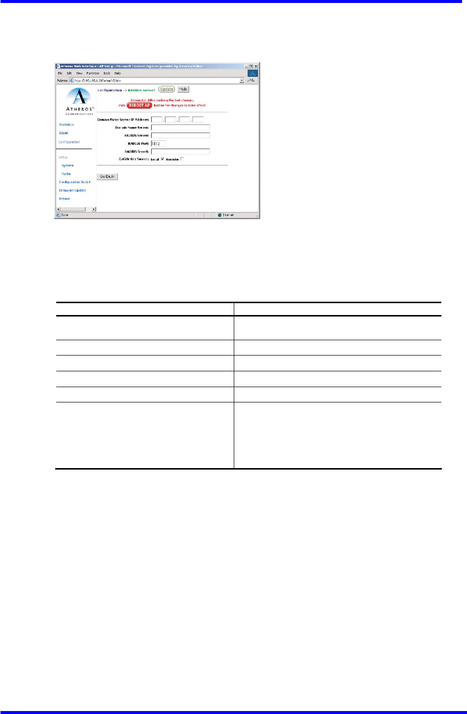
Edit Security Server Settings
The 2.4GHz Security configuration window allows configuration of a RADIUS server
for authentication purposes in 802.1x networks. See Figure A-15 for an illustration
of the RADIUS Server configuration window.
Figure A-15. 2.4GHz RADIUS Server Configuration Window
Table A-13 summarizes the data fields in the 2.4 GHz RADIUS Server configuration
window.
Table A-13. 2.4 GHz RADIUS Server Confi9uration Field Descriptions
Security Configuration Field Description
Domain Name Server IP Address Specifies the IP address of the domain name
server.
Domain Name Server Specifies the name of the domain name server.
RADIUS Server Specifies the IP address of the RADIUS server.
RADIUS Port Specifies the Port of the RADIUS server.
RADIUS Secret Specifies the Password for the RADIUS server.
RADIUS Key Source
Specifies the location of the RADIUS keys. Use
the “1oca1” check box to specify the RADIUS
keys are located in the AP. Use the “remote”
check box to specify the RADIUS keys are located
in the RADIUS server.
Dual band Access Point User’s Guide
Rev001, Page 31 of 41
2.4 GHz 802.1X Configuration
The IEEE 802.1X Protocol is designed to support port-based authentication and secure
key distribution. It can distribute unique encryption keys for an entire BSS. Honda
provides support for this protocol on the AP and the STA.
To enable 802.1x on the AP, take the following steps on the 2.4GHz RADIUS Server
configuration window (see Fi9ure A-15):
1. Specify the domain name server IP address.
2. Specify the name of the domain server.
3. Specify a RADIUS Server name and RADIUS Server secret.
4. Specify the location of the 2.4GHz Key Source as Remote.
5. Click the Update button, then after the last change to the AR click the Reboot
button to reboot the AP for the changes to take effect.
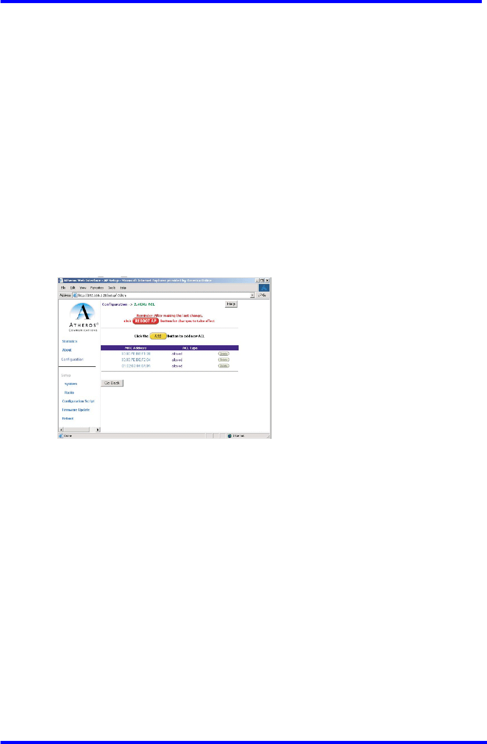
2.4 GHz Access Control List Configuration Window
The 2.4 GHz Radio configuration window allows AP security information setting. From
the 2.4 GHz Security configuration window, click Edit ACL Settings to access the
2.4 GHz ACL configuration window (see Fi8ure A-16)
Figure A-16. 2.4GHz Access Control List Configuration Window
Click Delete to remove any list item.
Dual band Access Point User’s Guide
Rev001, Page 32 of 41
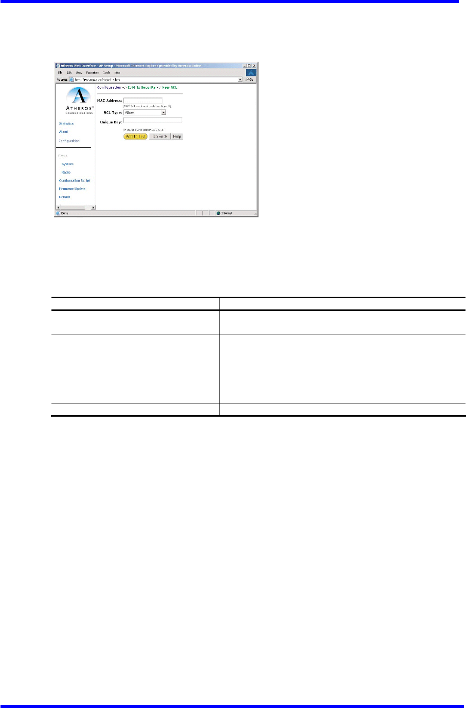
Adding New Access Control List
The 2.4GHzSecurity New ACL configuration window allows the addition of new access
control list items. From the 2.4 GHz ACL configuration window, click Add to list
to enter new list items (see Fig11re A-17).
Figure A-17. 2.4 GHz New ACL Configuration Window
Table A-14 summarizes the data fields in the New ACL configuration window. See Page
A-17 for instructions on adding items to the ACL.
Table A-14. 2.4GHz New Access Control List Field Descriptions
Per Station Privacy Field Description
MAC Address Specifies the MAC address for the STA to be included in
the ACL.
ACL Type
Specifies the current state of each STA:
■ Allow ‐ Enable access for this MAC address to the ACL.
■ Deny ‐ Deny access for this MAC address to the ACL.
■ Default Shared Key - This MAC address would use the
default shared key.
■ 64/128/152Bits - Specifies lengths for shared keys.
Unique Key Enter a unique key.
Dual band Access Point User’s Guide
Rev001, Page 33 of 41
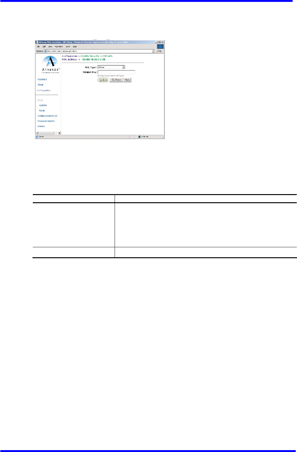
Adding Access Control List Permissions
The 2.4 GHz ACL configuration window allows the addition of permissions for each
list item. From the 2.4GHz ACL configuration window, click on a MAC address in the
list to view the 2.4GHz Security Edit ACL configuration window (see Figure A-18).
Figure A-18. 2.4GHz Security Edit ACL Configuration Window
Table A-15 summarizes the data fields in the 2.4GHz Security Edit ACL configuration
window.
Table A-15. 2.4GHz Security Edit Access Control List Field Descriptions
Per Station Privacy Field Description
Permission
Specifies the current state of each STA:
■ A11ow ‐ Enable access for this MAC address to the ACL.
■ Deny ‐ Deny access for this MAC address to the ACL.
■ Default Shared Key ‐ This MAC address would use the default
shared key.
■ 64/128/152Bits - Specifies lengths for shared keys
Unique Key Enter a unique key.
Dual band Access Point User’s Guide
Rev001, Page 34 of 41
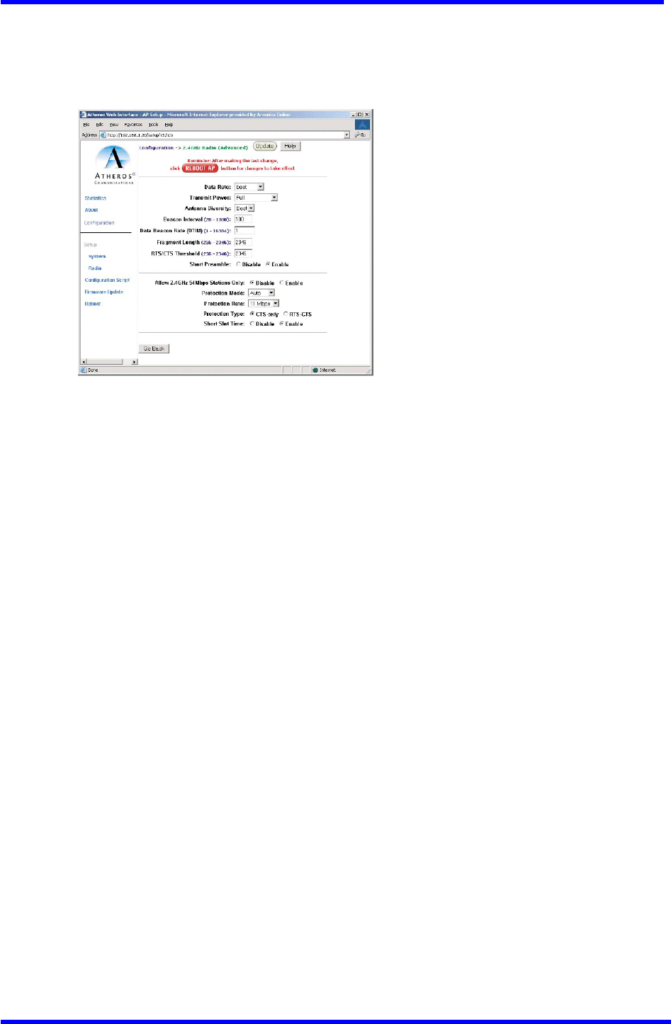
2.4 GHz Radio Advanced Configuration Window
The 2.4 GHz Radio (Advanced) configuration window allows the setting of
2.4GHzadvanced radio operating information for the AP. From the 2.4GHz Radio
configuration window, click Advanced to access the 2.4GHz Radio (Advanced)
configuration window (see Figure A-19).
Figure A-19. 2.4 GHz Radio Advanced Configuration Window
Table A-16 summarizes the data fields in the 2.4GHz Radio (Advanced) configuration
window.

Dual band Access Point User’s Guide
Rev001, Page 35 of 41
Table A-16. 2.4 GHz Radio Advanced Configuration Window Field Descriptions
Advanced Configuration Field Description
Data Rate Specifies the data transmission rate. Select the desired rate
from the drop-down menu. Selecting Best adapts the rate to
best available.
Transmit Power Specifies transmit Power level. Select the desired value from
the drop-down menu. Decrease the transmit Power if more than
one AP is co-located using the same channel frequency.
Antenna Diversity Specifies which antennae to use: Best, 1,or 2.
Beacon Interval Specifies the beacon interval value. Enter a value between
20 and 1000.
Data Beacon Rate Specifies the Data Beacon Rate. Enter a value between 1 and
16384 that Specifies the delivery traffic indicator message
(DTIM).
Fragment Length Specifies the fragment length. Enter a value between 256 and
2346.
RTS/CTS Threshold Specifies the value of the RTS/CTS threshold. Enter a value
between 256 and 2346.
Short Preamble Use the radio button to specify short preamble (11b) usage.
When enabled, both short and long preambles are used. When
disabled, only long preambles are used.
Allow 2.4GHz 54Mbps Station
Only Use the radio button to enable or disable the association of
2.4 GHz 54Mbps STA only.
Protection Mode Specifies the operation of CTS protection mode:
■ None
■ Always
■ Auto
Protection Rate Specifies the operation of CTS protection rate:
■ 1Mbps
■ 2Mbps
■ 5.5Mbps
■ 11Mbps
Protection Type Specifies the operation of CTS protection type:
■ CTS only
■ RTS-CTS
Short Shot Time Choose the radio button to specify short time shot usage.
Dual band Access Point User’s Guide
Rev001, Page 36 of 41
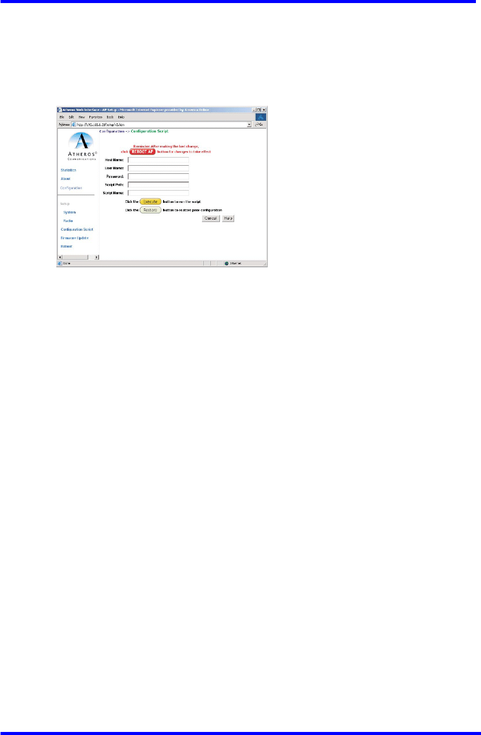
Script Configuration Window
The Script configuration window allows execution of text scripts of CLI commands
(e.g., construction of a text script to enter the shared keys for station).
All set command can be used in scripts, except set security, set password, find bss,
ftp, password, and ping.
Figure A-20 illustrates an example of an AP Script Configuration Window.
Figure A-20. Configuration Script Configuration Window
To use scripts:
1. Develop the scripts for the application.
2. Enter the host name where the script resides.
3. Enter the user name and password for the host.
4. Specify the script path and the script name in the data entry fields in the
Configuration Script window.
5. Click Execute to run the script.
To revert to the previous configuration, click Restore.
Dual band Access Point User’s Guide
Rev001, Page 37 of 41
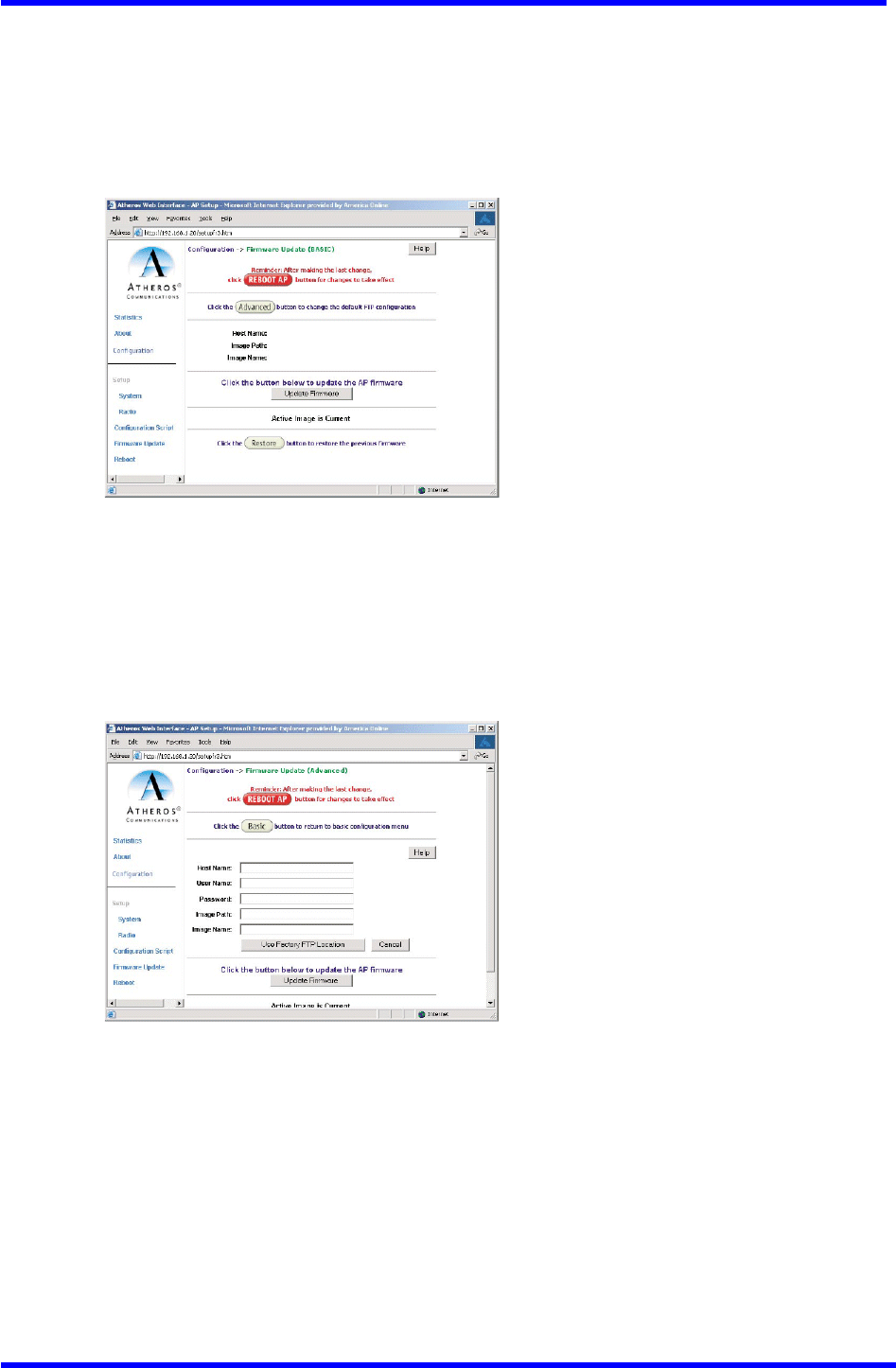
Firmware update Configuration Window
The Firmware Update Basic configuration window allows viewing of the FTP location
of new firmware. The default values for the Host Name, Image Path, and Image Name
appear in the window.
To access the Firmware Update window, click on Firmware Update in the navigation
bar. The Firmware Update configuration window appears (see Figure A-21).
Figure A-21. AP Firmware update Configuration Window
The AP uses the file transfer protoco1 (FTP) to download the Operating image from
the HPC. An FTP server utility is required to perform the data transfer between the
AP and HPC.
To enable firmware updates:
1. From the Firmware Update Basic window, click on Advanced. The AP Firmware
Update (Advanced) configuration window appears (see Figure A-22).
Figure A-22. Advanced Firmware update Configuration Window
The Firmware Update (Advanced) configuration window allows the setting of new
information on the FTP location of new firmware or filename of the firmware.
2. Enter the Host Name or host PC’s address, User Name, Password, Image Path,
and Image Name in the data-entry fields. To revert to the default-vendor values,
click use Factory FTP Location.
3. Click Update Firmware to store the new firmware changes. When Flash memory
contains two images, click Restore to toggle between these images. If Flash
memory contains only one image, the Restore button has no effect.
Dual band Access Point User’s Guide
Rev001, Page 38 of 41
Statistics Windows
From the AP Web Server, choose the Statistics hyperlink to go to the Access Point
Statistics window. By default, this is the first window that appears once the AP
Web Server opens (see Figure A-2).
The AP Statistics window allows viewing of the assigned ID, MAC address, and current
state of the AP and all stations currently part of its basic service set (BSS).The
toP-1eve1 Statistics window automatically updates each minute.
AP Statistics
To view statistics on the AP, click on the MAC address hyperlink for the desired
AP in the Statistics window. The BSS Stats window for the selected AP will appear.
See Figure A-23 for an example of a BSS Stats window (5GHz shown) for an AP.
Figure A-23. Basic Service Set Statistics Window for an AP
The BSS Stats window for AP is divided into sections that Provide the AP configuration,
AP SME statistics (station association information), or AP transmit and receive
statistics. Refer to Table A-17 for a description of the BSS Statistics for AP window
fields.

Dual band Access Point User’s Guide
Rev001, Page 39 of 41
Table A-17. BSS Statistics Field for AP Descriptions
The AP Stats window automatically updates every five seconds.
BSS Stats Field Description
State Current state of the AP.
Authentication Type Specifies open-system or shared key.
Encryption Specifies the enabled state of encryption; either yes
or no.
Cipher Advertised Specifies current state of advertised cipher
negotiations, AES and/or WEP, and None (clear).
Authentication / Deauthentication Number of times a STA attempted authentication and
deauthentication
Association / Deassociation /
Reassociation Number of times a STA attempted associations,
deassodations, and reassociations.
MSDU Maximum service data unit. Specifies the number of
Packets sent and received by the AP.
Data/Management/Control Packets can either be data, control or management.
Specifies the number of Packets sent and received for
each.
Multicast
Specifies the number of multicast Packets both sent and
received.
Errors
Specifies the error count for both transmit and receive.
Receive Errors Specifies the number of receive errors.
Discarded Frames Specifies the number of receive discarded frames.
Duplicate Frames Specifies the number of receive duplicate frames.
CRC Errors Specifies the number of receive CRC errors.
PHY Errors Specifies the number of receive PHY errors.
DMA Errors Specifies the number of receive DMA errors.
Transmit Errors Specifies the number of transmit errors.
Discarded Frames Specifies the number of transmit discarded frames.
Excessive Retries Specifies the number of transmit excessive retries.
DMA Errors Specifies the number of transmit DMA errors.

Dual band Access Point User’s Guide
Rev001, Page 40 of 41
Station Statistics
To view statistics on any STA, click on the MAC address hyperlink for the desired
STA. The BSS Stats window for the selected STA will appear. See Figure A-24 for an
example BSS Stats window for a station.
Figure A-24. Basic Service Set Statistics Window for Station
The BSS Stats window for stations provides the station configuration and statistics
for the selected station.
Table A-18 summarizes the information fields in the BSS Stats window for a STA.

Dual band Access Point User’s Guide
Rev001, Page 41 of 41
Table A-18. BSS Stats Fields for STA Descriptions
BSS Stats Window for STA Field Description
AID The ID of the STA.
State The current state of the STA
Power Save Specifies the enabled state of the Power save option;
either yes or no.
Encryption Specifies current state of encryption; AES and/or WEP, and
None (clear).
Advertised Cipher Specifies the supported cipher types.
Unicast Cipher Specifies the current unicast cipher type used.
Multicast Cipher Specifies the current multicast cipher type used.
Authentication/Deauthentication Number of times a STA attempted authentication and
deauthentication.
Association/Deassociation/Reass
ociation Number of times a STA attempted associations,
deassodations, and reassociations.
MSDU Maximum service data unit. Specifies the number of Packets
sent and received by the STA.
Data/Management/Control Packets can either be data, control or management.
Specifies the number of Packets sent and received for each.
Multicast Specifies the number of multicast frames.
Errors Specifies the error count for both transmit and receive
sides.
Signal Strength Specifies the strength of the transmit and receive signals
in dBm.
Data Rate (Mbps) Specifies the transmit and receive data rate in Mbps.
Receive Errors Specifies the number of receive errors.
Discarded Frames Specifies the number of receive discarded frames.
Duplicate Frames Specifies the number of receive duplicate frames.
CRC Errors Specifies the number of receive CRC errors.
PHY Errors Specifies the number of receive PHY errors.
DMA Errors Specifies the number of receive DMA errors.
Transmit Errors Specifies the number of transmit errors.
Discarded Frames Specifies the number of transmit discarded frames.
Excessive Retries Specifies the number of transmit excessive retries.
DMA Errors Specifies the number of transmit DMA errors.