Honda H5013 Owners Manual
!! Honda-86 Honda Power Equipment Lawn Mower Manuals - Lawn Mower Manuals – The Best Lawn Mower Manuals Collection
2014-11-13
: Honda Honda-H5013-Owners-Manual-108790 honda-h5013-owners-manual-108790 honda pdf
Open the PDF directly: View PDF ![]() .
.
Page Count: 109 [warning: Documents this large are best viewed by clicking the View PDF Link!]
- COVER
- CONTENTS
- SAFETY INFORMATION
- SERIAL NUMBERS
- COMPONENT IDENTIFICATION
- CONTROLS
- PRE-OPERATION CHECKS
- ENGINE OIL LEVEL
- AIR CLEANER ELEMENTS
- BATTERY ELECTROLYTE LEVEL
- COOLING SHROUD
- AIR INTAKE SCREEN
- FUEL LEAKAGE
- HYDRAULIC LIFT SYSTEM OIL LEAKAGE
- FRONT PTO BELT
- BRAKE PEDAL FREEPLAY
- BRAKE WEAR INDICATOR
- CLUTCH PEDAL FREEPLAY
- TIRES/WHEELS
- HYDRAULIC LIFT SYSTEM FLUID
- SEAT ADJUSTMENT
- STEERING
- FUEL LEVEL
- GASOLINE RECOMMENDATION
- GASOLINES CONTAINING ALCOHOL
- PARKING BRAKE
- HEADLIGHT
- SAFETY INTERLOCK SYSTEM
- HYDRAULIC LIFT SYSTEM
- OPERATION
- TRANSPORTING
- INSTALLING AN ATTACHMENT
- MAINTENANCE
- LONG TERM STORAGE
- WIRING DIAGRAM
- TROUBLESHOOTING
- SPECIFICATIONS
- WARRANTY SERVICE
- CURRENT CUSTOMER SERVICE CONTACT INFO


Thank you for purchasing a Honda tractor.
This manual describes operation and maintenance of the Honda H5013
tractor, type A2. (Two Wheel Drive Model) and A4 (Four Wheel Drive
Model).
Information in this manual is based on the H5013 A4 model equipped with
a rear hydraulic lift unit which is available as an optional part.
All information in this manual is based on the latest product information
available at the time of printing.
Honda Motor Co., Ltd. reserves the right to make changes at any time
without notice and without incurring any obligation.
No part of this publication may be reproduced without written permission.
This manual is considered a permanent part of the utility tractor and it
must stay with the tractor if resold.
READ THIS OWNER’S MANUAL CAREFULLY. Pay special attention to
these symbols and any instructions that follow:
pq -Indicates serious injury or death WILL result if
instructions are not followed.
m -
‘Indicates a strong possibility that serious injury or
death could result if instructions are not followed.
‘Indicates a possibility that minor injury can result if
instructions are not followed.
1 IMPORTANT NoT’CE 1 -Indicates that equipment or property damage can
result if instructions are not followed.
NOTE: Gives helpful information.
Honda tractors are designed to give safe and dependable service if
operated according to instructions. Operating this tractor requires special
effort on your part to ensure your safety and the safety of others.
y m Using this product for a purpose not intended may cause injury
or property damage. Read and understand this Owner’s Manual before
operating this tractor.
If a problem should arise, or if you have any questions about your tractor,
consult an authorized Honda tractor dealer.
HONDA MOTOR CO., LTD. 1990, ALL RIGHTS RESERVED
1
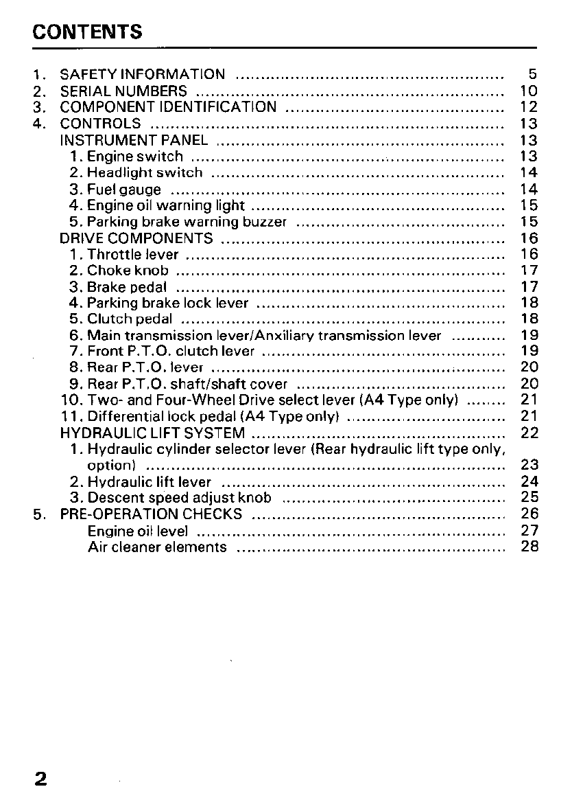
CONTENTS
1. SAFETY INFORMATION ...................................................... 5
2. SERIAL NUMBERS .............................................................. 10
3. COMPONENT IDENTIFICATION ............................................ 12
4. CONTROLS ....................................................................... 13
INSTRUMENT PANEL .......................................................... 13
1. Engine switch ............................................................... 13
2. Headlight switch ........................................................... 14
3. Fuel gauge ................................................................... 14
4. Engine oil warning light ................................................... 15
5. Parking brake warning buzzer .......................................... 15
DRIVE COMPONENTS ......................................................... 16
1 . Throttle lever ................................................................ 16
2. Choke knob .................................................................. 17
3. Brake pedal .................................................................. 17
4. Parking brake lock lever .................................................. 18
5. Clutch pedal ................................................................. 18
6. Main transmission lever/Anxiliary transmission lever ........... 19
7. Front P.T.O. clutch lever ................................................. 19
8. Rear P.T.O. lever ........................................................... 20
9. Rear P.T.O. shaft/shaft cover .......................................... 20
10. Two- and Four-Wheel Drive select lever (A4 Type only) ........ 21
1 1. Differential lock pedal (A4 Type only) ................................ 21
HYDRAULIC LIFT SYSTEM ................................................... 22
1. Hydraulic cylinder selector lever (Rear hydraulic lift type only,
option) ........................................................................ 23
2. Hydraulic lift lever ......................................................... 24
3. Descent speed adjust knob ............................................. 25
5. PRE-OPERATION CHECKS ................................................... 26
Engine oil level .............................................................. 27
Air cleaner elements ...................................................... 28
2
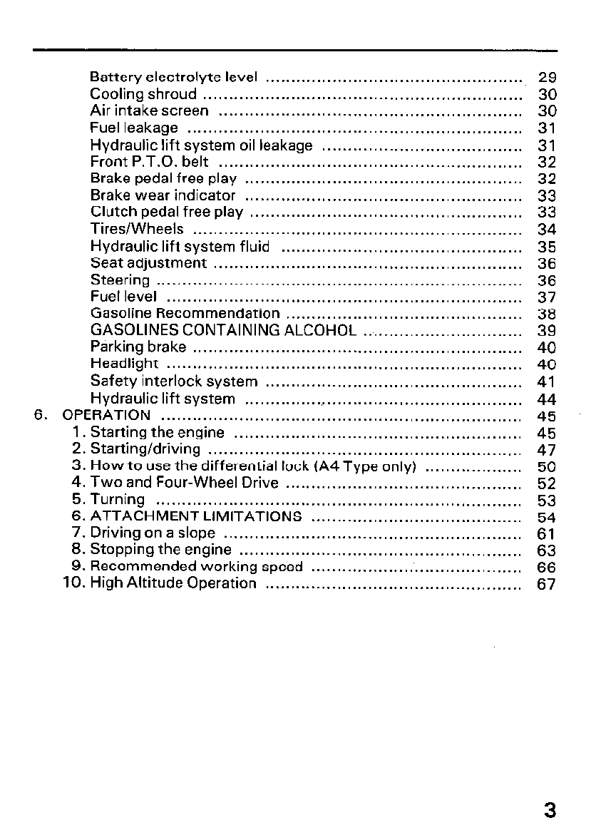
Battery electrolyte level ..................................................
Cooling shroud ..............................................................
Air intake screen ...........................................................
Fuel leakage .................................................................
Hydraulic lift system oil leakage .......................................
Front P.T.O. belt ...........................................................
Brake pedal free play ......................................................
Brake wear indicator ......................................................
Clutch pedal free play .....................................................
Tires/Wheels ................................................................
Hydraulic lift system fluid ...............................................
Seat adjustment ............................................................
Steering .......................................................................
Fuel level .....................................................................
Gasoline Recommendation ..............................................
GASOLINES CONTAINING ALCOHOL ...............................
Parking brake ................................................................
Headlight .....................................................................
Safety interlock system ..................................................
Hydraulic lift system .......................................................
6. OPERATION ......................................................................
1. Starting the engine ........................................................
2. Starting/driving .............................................................
3. How to use the differential lock (A4 Type only) ...................
4. Two and Four-Wheel Drive ..............................................
5. Turning .......................................................................
6. ATTACHMENT LIMITATIONS .........................................
7. Driving on a slope ..........................................................
8. Stopping the engine .......................................................
9. Recommended working speed .........................................
10. High Altitude Operation ..................................................
29
30
30
31
31
32
32
33
33
34
35
36
36
37
E
40
40
41
44
45
45
47
50
52
53
54
61
63
66
67
3
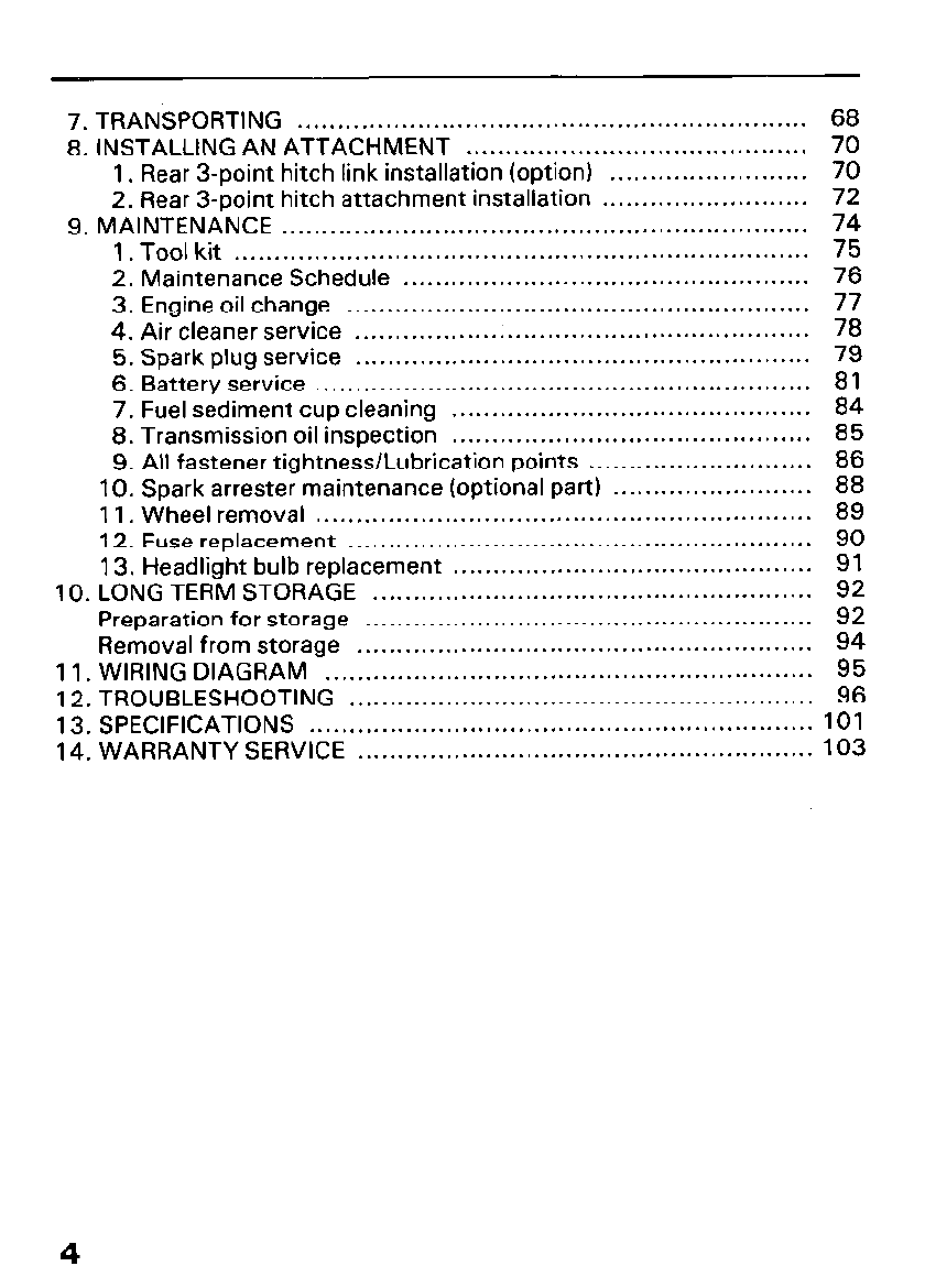
7. TRANSPORTING . . . . . . . . . . . . . . . . . . . . . . . . . . . . . . . . . . . . . . . . . . . . . . . . . . . . . . .
. . . . . . . . . 68
8. INSTALLING AN ATTACHMENT . . . . . . . . . . . . . . . . . . . . . . . . . . . . . . . . . . . . . . . . . . . 70
1. Rear 3-point hitch link installation (option) . . . . . . . . . . . . . . . . . . . . . . . . . 70
2. Rear 3-point hitch attachment installation . . . . . . . . . . . . . . . . . . . . . . . . . . 72
9. MAINTENANCE . . . . . . . . . . . . . . . . . . . . . . . . . . . . . . . . . . . . . . . . . . . . . . . . . . . . . . . . . . . . . . . . . . 74
1. Tool kit . . . . . . . . . . . . . . . . . . . . . . . . . . . . . . . . . . . . . . . . . . . . . . . . . . . . . . . . . . . . . . . . . . . . . . . . 75
2. Maintenance Schedule . . . . . . . . . . . . . . . . . . . . . . . . . . . . . . . . . . . . . . . . . . . . . . . . . . . 76
3. Engine oil change . . . . . . . . . . . . . . . . . . . . . . . . . . . . . . . . . . . . . . . . . . . . . . . . . . . . . . . . . . 77
4. Air cleaner service . . . . . . . . . . . . . . . . . . . . . . . . . . . . . . . . . . . . . . . . . . . . . . . . . . . . . . . . . 78
5. Spark plug service . . . . . . . . . . . . . . . . . . . . . . . . . . . . . . . . . . . . . . . . . . . . . . . . . . . . . . . . . 79
6. Battery service . . . . . . . . . . . . . . . . . . . . . . . . . . . . . . . . . . . . . . . . . . . . . . . . . . . . . . . . . . . . . . 81
7. Fuel sediment cup cleaning . . . . . . . . . . . . . . . . . . . . . . . . . . . . . . . . . . . . . . . . . . . . . 84
8. Transmission oil inspection . . . . . . . . . . . . . . . . . . . . . . . . . . . . . . . . . . . . . . . . . . . . . 85
9. All fastener tightness/Lubrication points . . . . . . . . . . . . . . . . . . ..a....... 86
10. Spark arrester maintenance (optional part) . . . . . . . . . . . . . . . . . . . . . . . . . 88
11. Wheel removal . . . . . . . . . . . . . . . . . . . . . . . . . . . . . . . . . . . . . . . . . . . . . . . . . . . . . . . . . . . . . . 89
12. Fuse replacement . . . . . . . . . . . . . . . . . . . . . . . . . . . . . . . . . . . . . . . . . . . . . . . . . . . . . . . . . . 90
13. Headlight bulb replacement . . . . . . . . . . . . . . . . . . . . . . . . . . . . . . . . . . . . . . . . . . . . . 91
10. LONG TERM STORAGE . . . . . . . . . . . . . . . . . . . . . . . . . . . . . . . . . . . . . . . . . . . . . . . . . . . . . . . 92
Preparation for storage . . . . . . . . . . . . . . . . . . . . . . . . . . . . . . . . . . . . . . . . . . . . . . . . . . . . . . . . 92
Removal from storage . . . . . . . . . . . . . . . . . . . . . . . . . . . . . . . . . . . . . . . . . . . . . . . . . . . . . . . . . 94
11. WIRING DIAGRAM . . . . . . . . . . . . . . . . . . . . . . . . . . . . . . . . . . . . . . . . . . . . . . . . . . . . . . . . . . . . . 95
12. TROUBLESHOOTING . . . . . . . . . . . . . . . . . . . . . . . . . . . . . . . . . . . . . . . . . . . . . . . . . . . . . . . . . . 96
13. SPECIFICATIONS . . . . . . . . . . . . . . . . . . . . . . . . . . . . . . . . . . . . . . . . . . . . . . . . . . . . . . . . . . . . . . . 101
14. WARRANTY SERVICE . . . . . . . . . . . . . . . . . . . . . . . . . . . . . . . . . . . . . . . . . . . . . . . . . . . . . . . . . 103
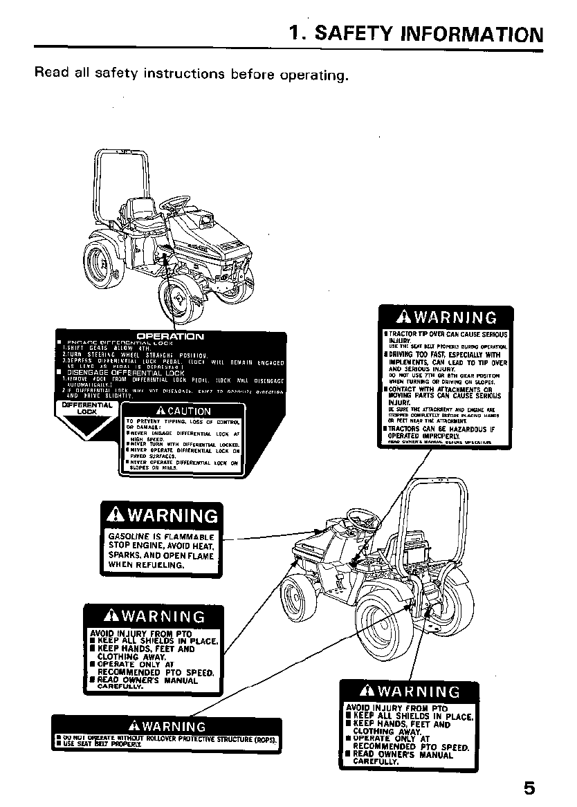
1. SAFETY INFORMATION
Read all safety instructions before operating.
/&==a
.
/
5
TRACTOR SAFETY
m Operation of the tractor and its attachments requires special
efforts on your part to ensure your safety and the safety of others. Know
these requirements before you operate the Tractor or its attachments:
SAFE OPERATING RULES
l Severe personal injury or equipment damage may result if the pre-
operation inspection (Page 26) is not performed before operating the
tractor or its attachments.
l To avoid severe personal injury or equipment damage, observe the
following precautions:
l All parts, epecially guards and shields, should be in good condition,
and securely fastened in place.
l Do not remove any guards, warning labels, shields or safety devices;
they are installed for your safety.
l The rollover protective structure (ROPS) will only help protect you
from injury, if:
- you are also wearing the seat belt.
- the ROPS is securely attached and has not been modified or struc-
turally damaged.
l Always wear sturdy shoes and avoid wearing bulky or loose clothing
while operating the tractor or its attachments.
l Never operate the tractor or its attachments when tired or while
under the influence of drugs or alcohol.
l In case of emergency, know how to stop the engine and thoroughly
understand the operation of ALL controls.
l Never permit anyone to operate the tractor or its attachments
without proper instructions.
l Children should not be permitted to operate the tractor or any of its
attachments.
. KEEP CHILDREN AND PETS AT A SAFE DISTANCE DURING OPE-
RATION
l This is an operator only vehicle, do not allow passengers to ride on
the tractor or on any of its attachments.
; The exhaust contains poisonous carbon monoxide gas that can
cause loss of consciousness and may lead to death, if the tractor is
operated in an enclosed space.
6
BEFORE STARTING
l The use of heavy equipment and/or pulling excessive loads may
adversely affect vehicle stability and control. To avoid loss of control
that can result in severe personal injury:
- Only use recommended hitch attachment points.
- Limit loads to as suggested on page 54.
- Be extra careful when turning or backing up.
- Use counterweight(s) as suggested on page 58.
l Before installing or using any attachment, carefully read all instructions
and precautions.
OPERATION
l
l
l
l
l
Be sure to fasten the seat belt whenever driving the tractor with the
Rollover Protective Structure (ROPS) attached. Use of either device
(seat belt or ROPS) without the other will increase the chance of injury
in a rollover.
Adjust the seat belt so that it is snug.
Be sure that the main Transmission lever is in “Neutral” and the front
and rear P.T.O. levers are in the “OFF” position before starting the
engine.
Operate the tractor at low speed until you become familiar with all of its
operating characteristics and controls.
Do not operate the tractor or its attachments without ensuring the area
in front and behind is clear of people and pets.
Sudden stops of the tractor while driving at high speed or sudden start-
up with the steering wheels turned fully in one direction, could cause
the tractor to overturn.
This tractor utilizes Four Wheel Steering (4WS) for a tighter turning cir-
cle and greater mobility than tractors with conventional steering.
However, the feel of 4WS is slightly different from other tractors. Prac-
tice driving in a wide, safe area.
Never operate the tractor or its attachments when visibility is diminish-
ed by darkness or bad weather; your ability to see obstacles will
become impaired.
Watch out for rocks, roots, holes and other obstacles that may cause
the Tractor to overturn.
This tractor and its attachments are intended for use on relatively flat
terrain.
It is illegal to operate this tractor on public streets, roads, or highways.
It is legal in some areas to operate a tractor without a U.S.D.A. qualified
spark arrester. Check local laws and regulations before operating. An
optional spark arrester for this product is available from your authorised
Honda tractor dealer. 7
l When operating the tractor on a slope, always drive up and down the
face of the grade. Turning or driving across the face of a slope may
cause the tractor to overturn.
l To avoid loss of control or overturning, always reduce speed and exer-
cise extreme caution when operating on sloping or uneven surfaces.
l Attempting to change gears while operating the tractor on a slope may
adversely affect vehicle stability and control and severe personal injury
could result.
l Do not back down, or rapidly accelerate up, a sloping surface.
l To avoid loss of control or overturning, do not turn or stop on sloping
surfaces.
l When descending a slope, disengaging the clutch or shifting to neutral
can cause a loss of control that may result in severe personal injury.
l Do not operate the tractor near the edge of a ditch or an embankment.
Slipping off the edge could lead to severe personal injury and equipment
damage.
To avoid injury to yourself and others, before leaving the Tractor unattend-
ed, ALWAYS.
- park on level ground.
- disengage the power take-off.
- lower the attachment(s).
- Lock the parking brake.
- stop the engine.
- and remove the key.
l If you find it necessary to park on a grade, be sure to lock the parking
brake and securely block the wheels.
l Be sure to follow the instructions below whenever applying the dif-
ferential lock.
- Be sure that the main transmission lever is set in 4th gear or lower,
and reduce engine speed before applying the differential lock.
- Do not apply while turning the tractor.
Use the lock only when driving straight ahead.
- Do not rest your foot on the lock pedal while the lock is not in use.
- Never apply while driving on a paved surface.
MAINTENANCE SAFETY
Before performing maintenance/inspection, read the instructions
thoroughly.
Before cleaning, inspecting or servicing the tractor, be sure to
- Move the P.T.O. lever to the “OFF” position and lower any
attachments.
- Stop the engine and remove the key.
- Remove the spark plug cap.
If you hit an object, stop the engine and inspect the Tractor and its
attachments.
Fix any damage before you resume operation.
Operating the tractor with damaged, worn or broken parts may result in
severe personal injury.
Leaves, grass clippings, oil and other combustible materials can
become a fire hazard. Be sure the body, engine and drive mechanism
areas are kept clean.
All nuts, bolts and fasteners must be tight.
Do not change the engine governor settings or the engine may be
damaged.
STORAGE SAFETY
l To avoid the possibility of fire, allow the engine and exhaust system to
cool before storing the tractor in an enclosed space or near combustible
materials.
l When storing the tractor, be sure to apply the parking brake and remove
the engine key.
l Drain all gasoline from the carburetor and fuel tank, and disconnect the
battery ground cable.
9
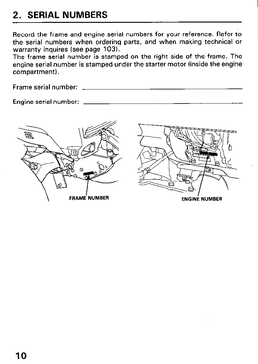
2. SERIAL NUMBERS
Record the frame and engine serial numbers for your reference. Refer to
the serial numbers when ordering parts, and when making technical or
warranty inquires (see page 103).
The frame serial number is stamped on the right side of the frame. The
engine serial number is stamped under the starter motor (inside the engine
compartment).
Frame serial number:
Engine serial number:
ENGINE NUMBER
10
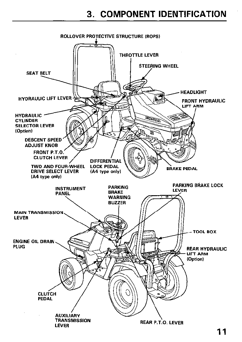
3. COMPONENT IDENTIFICATION
ROLLOVER PROTECTIVE STRUCTURE (ROPS)
THROTTLE LEVER
STEERING WHEEL
SEAT BELT /
HYDRAULIC LIFT LEVER
HYDRAULIC
CYLINDER
SELECTOR LEVER
(Option)
DESCENT SPEED
ADJUST KNOB
FRONT P.T.O.
MAIN 1
LEVER
ENGINE
PLUG
CLUTCH LEVER / DIFFEREN AL
TWO AND FOUR-WHEEL LOCK PEDAL
DRIVE SELECT LEVER (A4 type only)
(A4 type only)
BRAKE PEDAL
JLIC
INSTRUMENT
PANEL
\
PARKING PARKING BRAKE LOCK
BRAKE LEVER
WARNING
‘RANSMISSION
REAR HYDRAULIC
LEVER 11
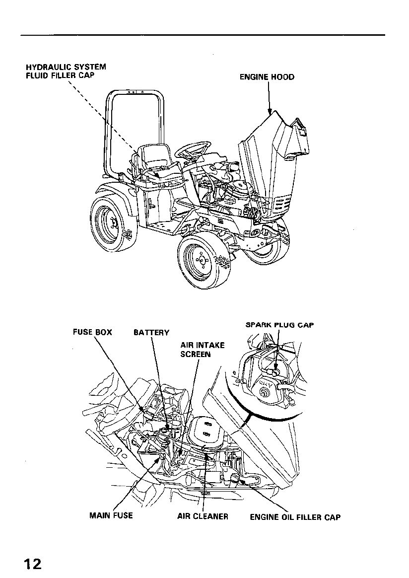
HYDRAULIC SYSTEM
FLUID FILLER CAP
\ ENGINE HOOD
FUSE BOX SPARK PLUG CAP
MAIN FUSE AIR CLEANER ENGINE OIL FILLER CAP
12
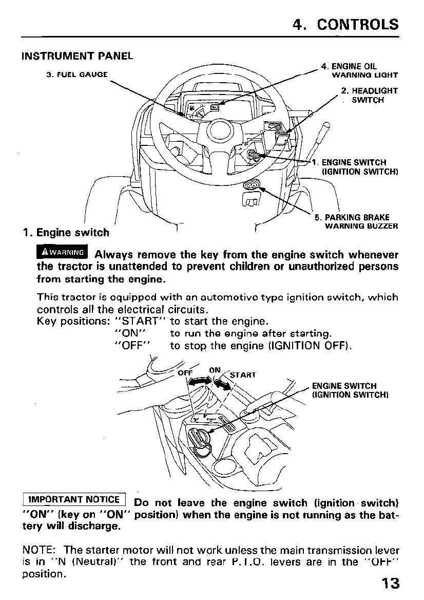
4. CONTROLS
INSTRUMENT PANEL 4. ENGINE OIL
3. FUEL GAUGE WARNING LIGHT
2. HEADLIGHT
ITION SWITCH)
1. Engine switch
m Always remove the key from the engine switch whenever
the tractor is unattended to prevent children or unauthorized persons
from starting the engine.
This tractor is equipped with an automotive type ignition switch, which
controls all the electrical circuits.
Key positions: “START” to start the engine.
“ON” to run the engine after starting.
“OFF” to stop the engine (IGNITION OFF).
ENGINE SWITCH
(IGNITION SWITCHI
IMPORTANT NOTICE 1 Do not leave the engine switch (ignition’ switch)
“ON” (key on “ON” position) when the engine is not running as the bat-
tery will discharge.
NOTE: The starter motor will not work unless the main transmission lever
is in “N (Neutral)” the front and rear P.T.O. levers are in the “OFF”
position. 13
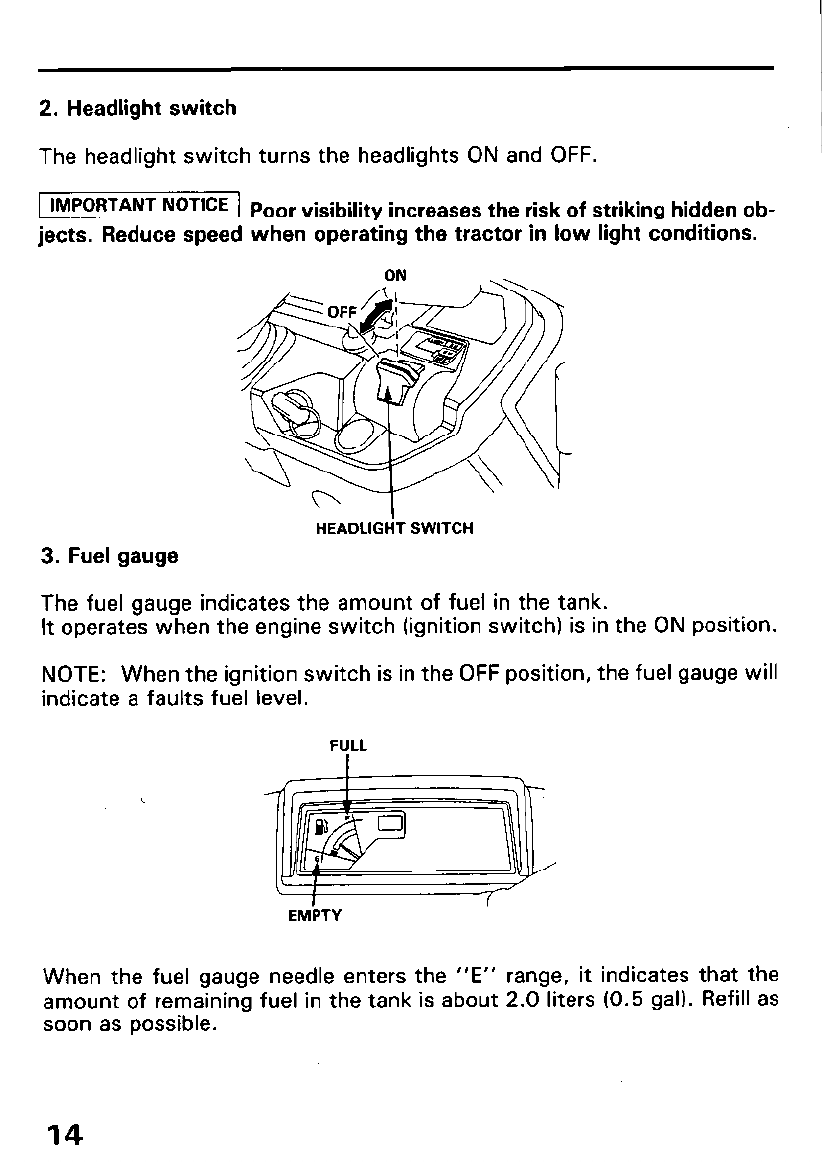
2. Headlight switch
The headlight switch turns the headlights ON and OFF.
[ IMPORTANT NOTICE 1 p oor visibility increases the risk of striking hidden ob-
jects. Reduce speed when operating the tractor in low light conditions.
3. Fuel gauge
HEADLIGHT SWITCH
The fuel gauge indicates the amount of fuel in the tank.
It operates when the engine switch (ignition switch) is in the ON position.
NOTE: When the ignition switch is in the OFF position, the fuel gauge will
indicate a faults fuel level.
EMPTY EMPTY
When the fuel gauge needle enters the “E” range, it indicates that the
amount of remaining fuel in the tank is about 2.0 liters (0.5 gal). Refill as
soon as possible.
14
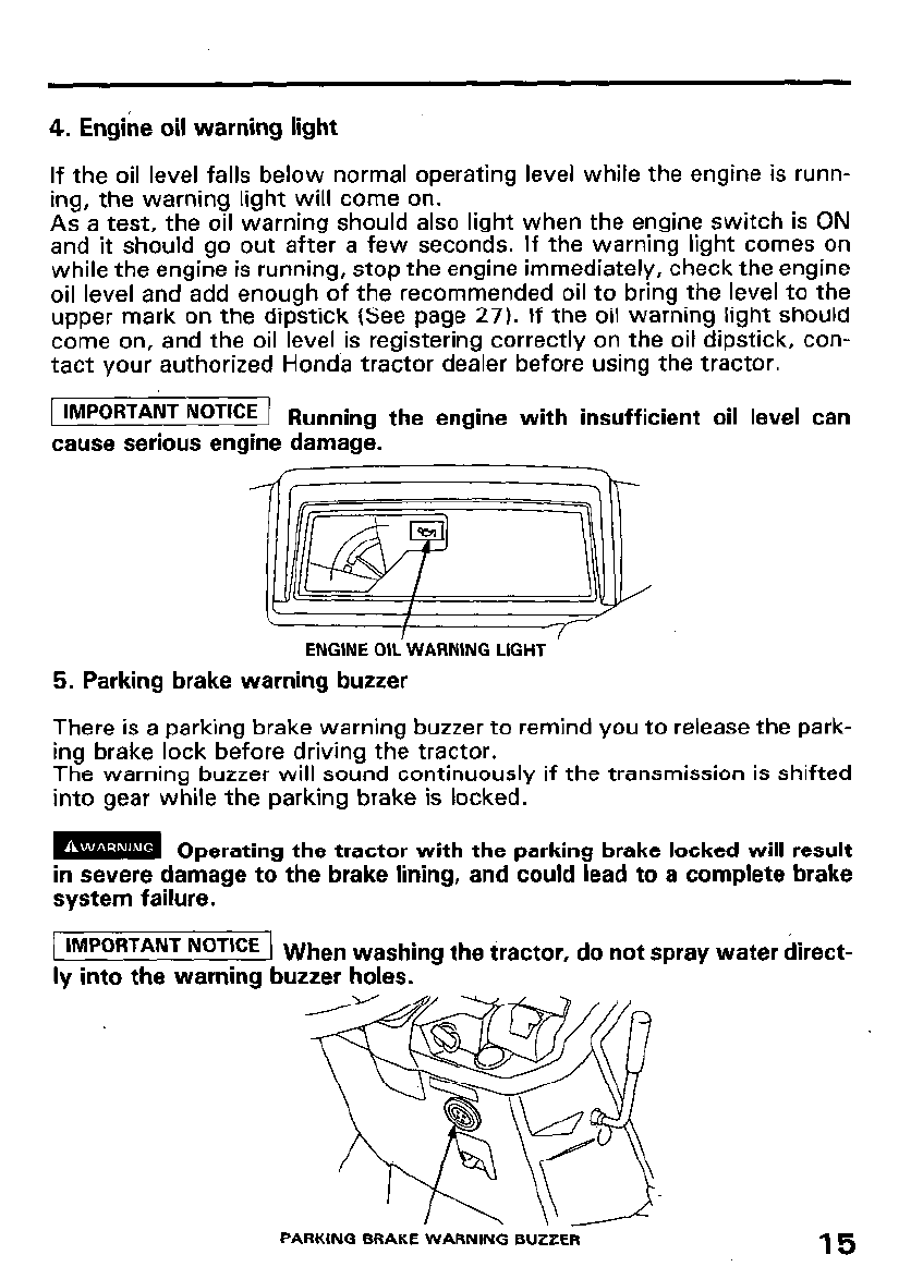
4. Engine oil warning light
If the oil level falls below normal operating level while the engine is runn-
ing, the warning light will come on.
As a test, the oil warning should also light when the engine switch is ON
and it should go out after a few seconds. If the warning light comes on
while the engine is running, stop the engine immediately, check the engine
oil level and add enough of the recommended oil to bring the level to the
upper mark on the dipstick (See page 27). If the oil warning light should
come on, and the oil level is registering correctly on the oil dipstick, con-
tact your authorized Honda tractor dealer before using the tractor.
IMPORTANT NOTICE 1 Running the engine with insufficient oil level can
cause serious engine damage.
ENGINE OIL WARNING LIGHT
5. Parking brake warning buzzer
There is a parking brake warning buzzer to remind you to release the park-
ing brake lock before driving the tractor.
The warning buzzer will sound continuously if the transmission is shifted
into gear while the parking brake is locked.
m Operating the tractor with the parking brake locked will result
in severe damage to the brake lining, and could lead to a complete brake
system failure.
1 IMPORTANT NOTICE ) Wh en washing the tractor, do not spray water direct-
ly into the warning buzzer holes.
PARKING BRAKE WARNING BUZZER 15
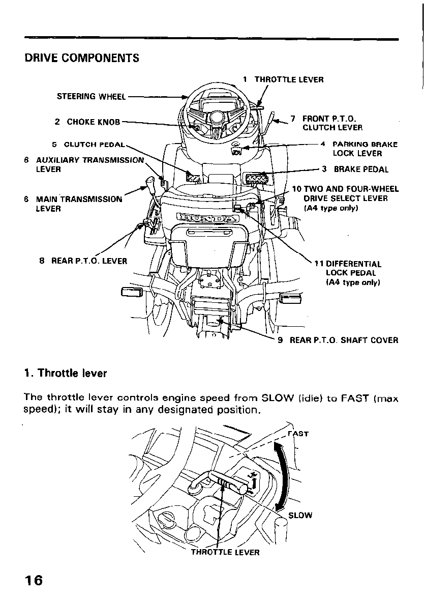
ROTTLE LEVER
I
STEERING WHEEL
7 FRONT P.T.O.
I I-\,#-”
DRIVE COMPONENTS
2 CHOKE KNOB
5 CLUTCH PEDAL 4 PARKING BRAKE
LOCK LEVER
6 AUXILIARY TRANSMIS
LEVER 3 BRAKE PEDAL
10 TWO AND FOUR-WHEEL
6 MAIN ‘TRANSMISSION DRIVE SELECT LEVER
LEVER
8 REAR P.T. 11 DIFFERENTIAL
LOCK PEDAL
(A4 type only)
REAR P.T.O. SHAFT COVER
1. Throttle lever
The throttle lever controls engine speed from SLOW (idle) to FAST (max
speed); it will stay in any designated position.
16
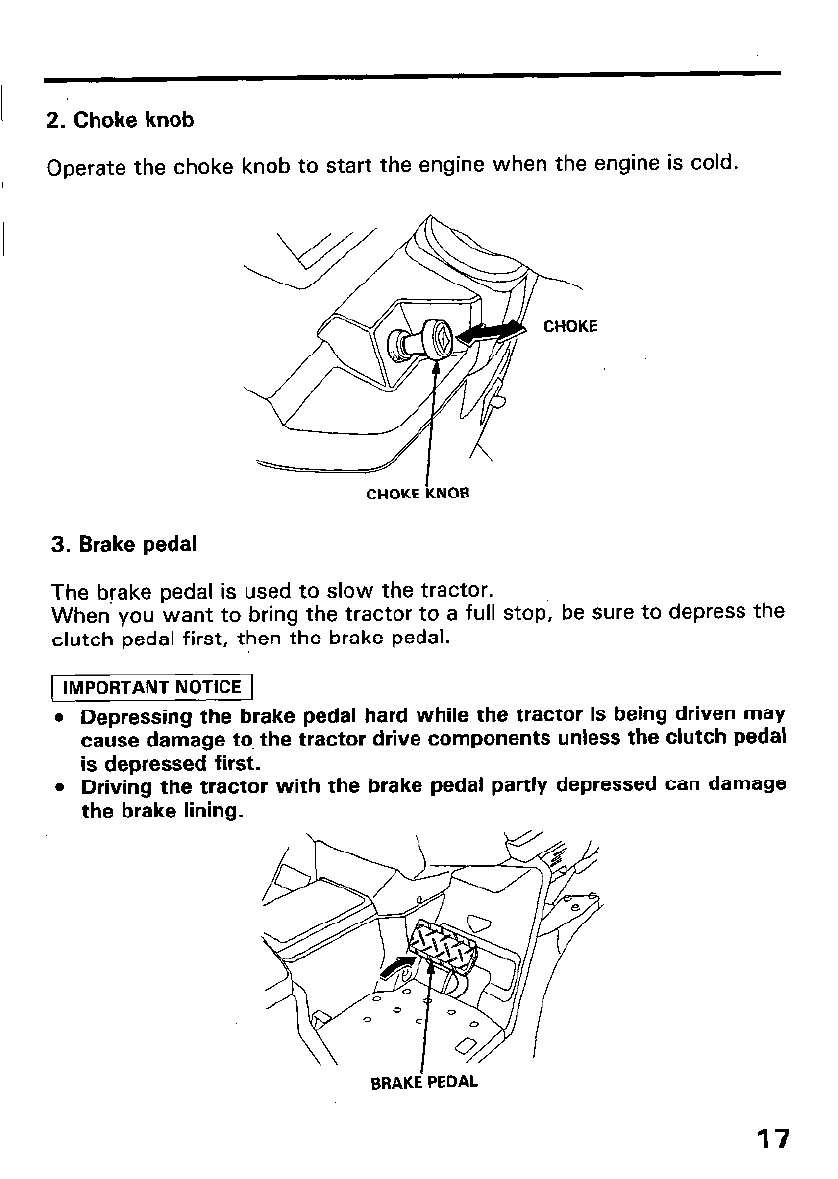
2. Choke knob
Operate the choke knob to start the engine when the engine is cold.
CHOKE KNOB
3. Brake pedal
The brake pedal is used to slow the tractor.
When you want to bring the tractor to a full stop, be sure to depress the
clutch pedal first, then the brake pedal.
[ IMPORTANT NOTICE 1
l Depressing the brake pedal hard while the tractor is being driven may
cause damage to the tractor drive components unless the clutch pedal
is depressed first.
l Driving the tractor with the brake pedal partly depressed can damage
the brake lining.
BRAKE’ PEDAL
17
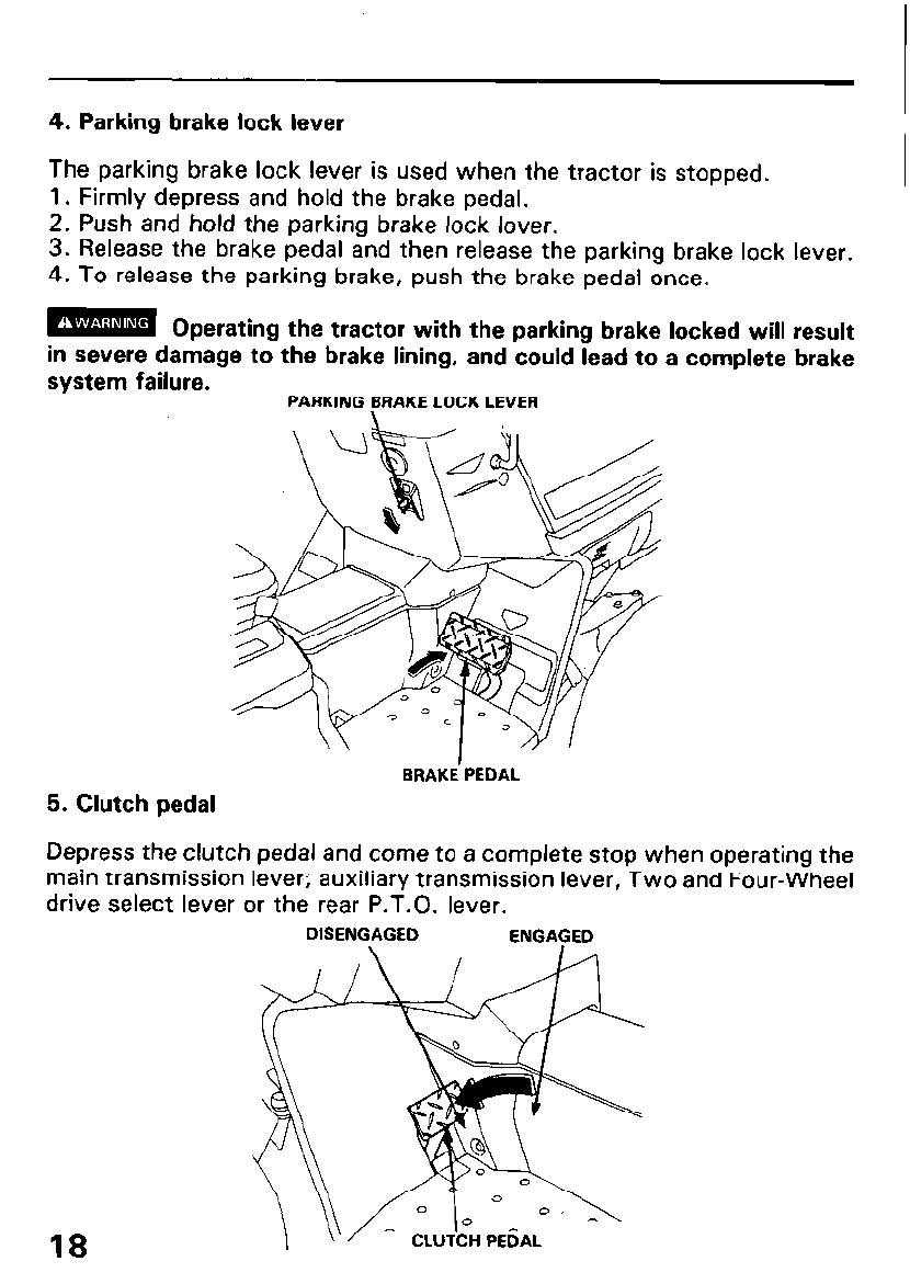
4. Parking brake lock lever
The parking brake lock lever is used when the tractor is stopped.
1. Firmly depress and hold the brake pedal.
2. Push and hold the parking brake lock lover.
3. Release the brake pedal and then release the parking brake lock lever.
4. To release the parking brake, push the brake pedal once.
m Operating the tractor with the parking brake locked will result
in severe damage to the brake lining, and could lead to a complete brake
system failure. PARKING BRAKE LOCK LEVER
5. Clutch pedal
BRAKE’PEDAL
Depress the clutch pedal and come to a complete stop when operating the
main transmission lever; auxiliary transmission lever, Two and Four-Wheel
drive select lever or the rear P.T.O. lever.
DISENGAGED ENGAGED
18
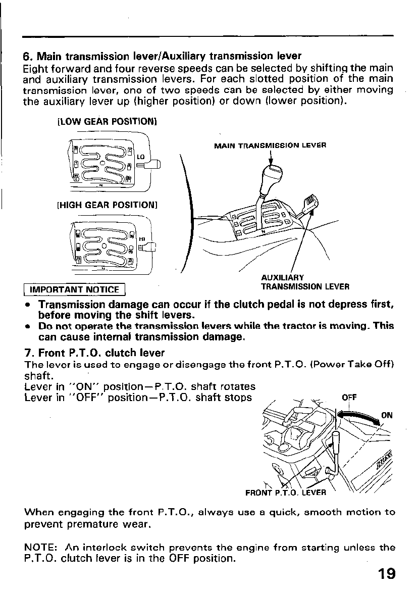
6. Main transmission lever/Auxiliary transmission lever
Eight forward and four reverse speeds can be selected by shifting the main
and auxiliary transmission levers. For each slotted position of the main
transmission lever, one of two speeds can be selected by either moving
the auxiliary lever up (higher position) or down (lower position).
[LOW GEAR POSITION1
c--,7
[HIGH GEAR POSITION]
r-----Y-\
MAIN TRANSMISSION LEVER
Al IXll IARY
. .-_..-._ . . . .
( IMPORTANT NOTICE ( TRANSMISSION LEVER
l Transmission damage can occur if the clutch pedal is not depress
before moving the shift levers.
l Do not operate the transmission levers while the tractor is moving.
can cause internal transmission damage.
first,
, This
7. Front P.T.O. clutch lever
The lever is used to engage or disengage the front P.T.O. (Power Take Off)
shaft.
Lever in “ON” position-P.T.O. shaft rotates
Lever in “OFF” position-P.T.O. shaft stops
When engaging the front P.T.O., always use a quick, smooth motion to
prevent premature wear.
NOTE: An interlock switch prevents the engine from starting unless the
P.T.O. clutch lever is in the OFF position.
19
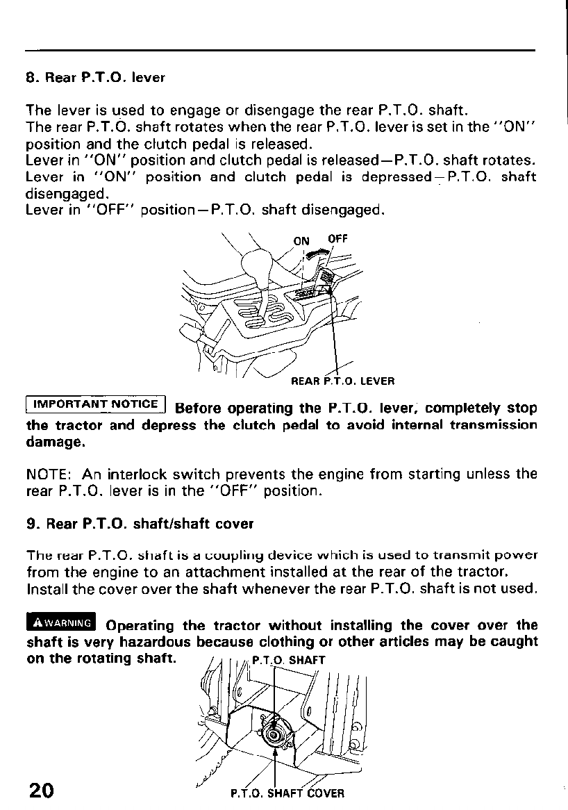
8. Rear P.T.O. lever
The lever is u,sed to engage or disengage the rear P.T.O. shaft.
The rear P.T.O. shaft rotates when the rear P.T.O. lever is set in the “ON”
position and the clutch pedal is released.
Lever in “ON” position and clutch pedal is released-P.T.O. shaft rotates.
Lever in “ON” position and clutch pedal is depressedTP.T.O. shaft
disengaged.
Lever in “OFF” position-P.T.O. shaft disengaged.
1 IMPORTANT NOTICE 1 8 e ore operating the P.T.O. lever, completely stop
f
the tractor and depress the clutch pedal to avoid internal transmission
damage.
NOTE: An interlock switch prevents the engine from starting unless the
rear P.T.O. lever is in the “OFF” position.
9. Rear P.T.O. shaft/shaft cover
The rear P.T.O. shaft is a coupling device which is used to transmit power
from the engine to an attachment installed at the rear of the tractor.
Install the cover over the shaft whenever the rear P.T.O. shaft is not used.
m Operating the tractor without installing the cover over the
shaft is very hazardous because clothing or other articles may be caught
on the rotating shaft.
20 P.T.O. SHAFT COVER
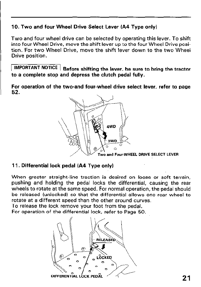
10. Two and four Wheel Drive Select Lever (A4 Type only)
Two and four wheel drive can be selected by operating this lever. To shift
into four Wheel Drive, move the shift lever up to the four Wheel Drive posi-
tion. For two Wheel Drive, move the shift lever down to the two Wheel
Drive position.
( IMPORTANT NOTICE 1 B e
f ore shifting the lever, be sure to bring the tractor
to a complete stop and depress the clutch pedal fully.
For
52.
operation of the two-and four-wheel drive select lever, refer to page
DRIVE SELECT LEVER
11, Differential lock pedal (A4 Type only)
When greater straight-line traction is desired on loose or soft terrain,
pushing and holding the pedal locks the differential, causing the rear
wheels to rotate at the same speed. For normal operation, the pedal should
be released (unlocked) so that the differential allows one rear wheel to
rotate at a different speed than the other around curves.
To release the lock remove your foot from the pedal.
For operation of the differential lock, refer to Page 50.
21
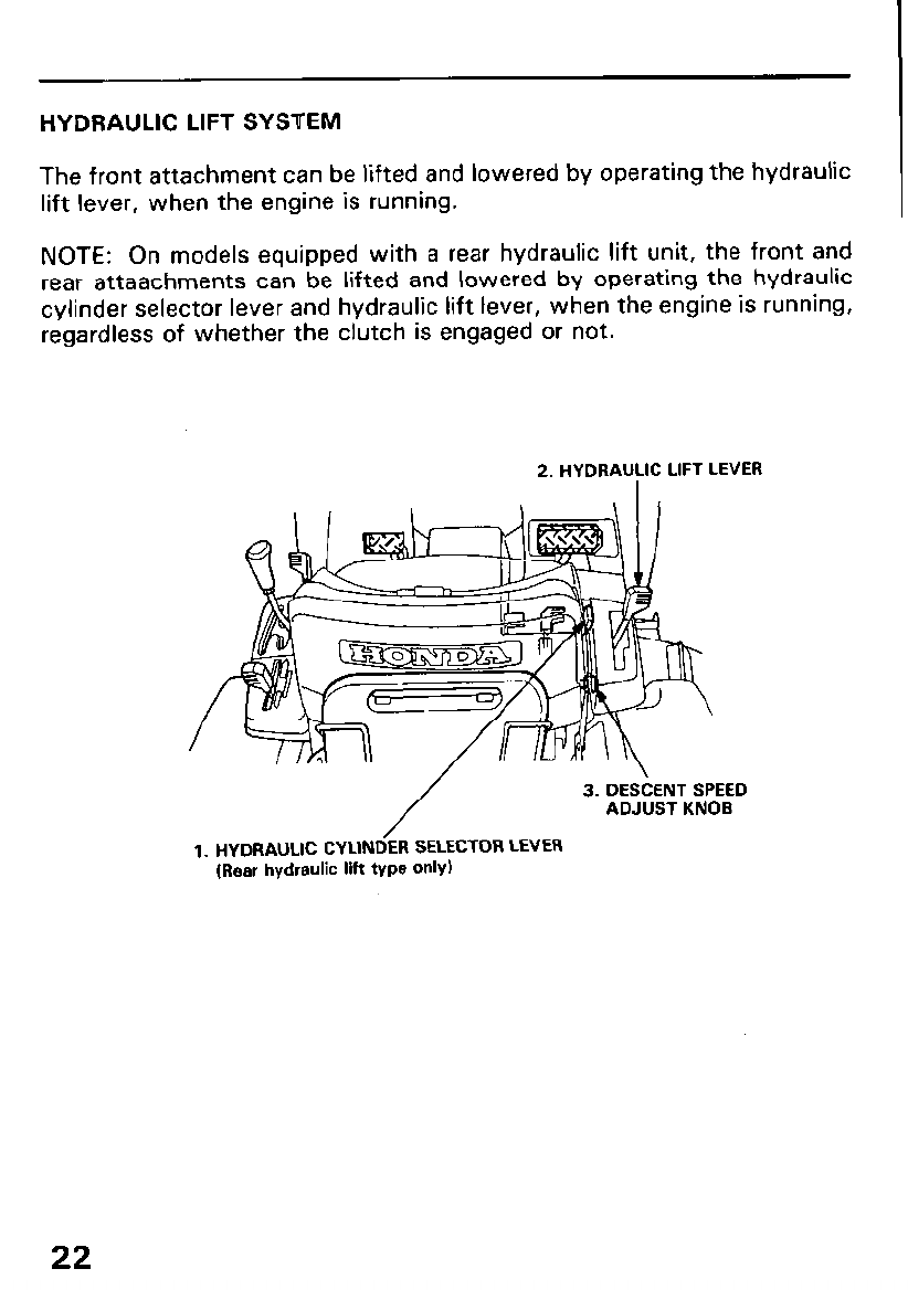
HYDRAULIC LIFT SYSTEM
The front attachment can be lifted and lowered by operating the hydraulic
lift lever, when the engine is running.
NOTE: On models equipped with a rear hydraulic lift unit, the front and
rear attaachments can be lifted and lowered by operating the hydraulic
cylinder selector lever and hydraulic lift lever, when the engine is running,
regardless of whether the clutch is engaged or not.
2. HYDRAULIC LIFT LEVER
/ ADJUST KNOB
1. HYDRAULIC CYLINDER SELECTOR LEVER
(Rear hydraulic lift type only)
22
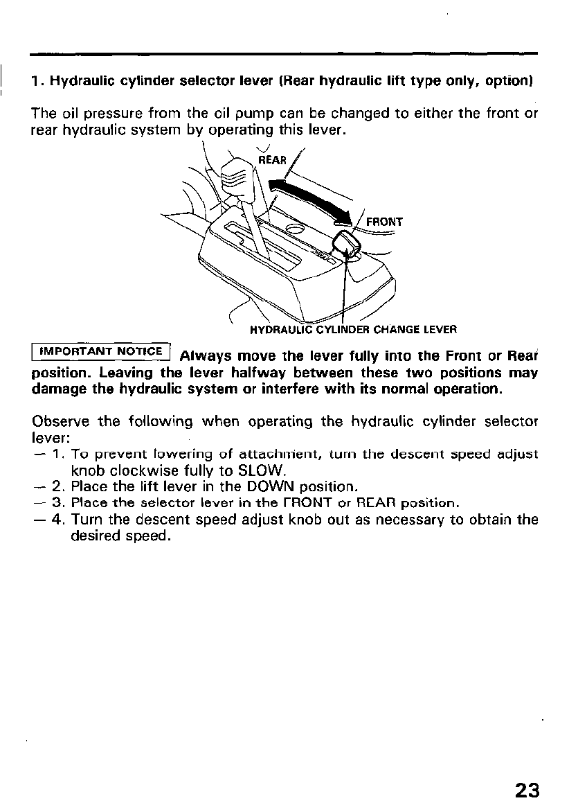
1. Hydraulic cylinder selector lever (Rear hydraulic lift type only, option)
The
rear
the front or
oil pressure from the oil pump can be changed to either oil pressure from the oil pump can be changed to either the front or
hydraulic system by operating this lever. hydraulic system by operating this lever.
T T
HYDRAULIC CYLINDER CHANGE LEVER HYDRAULIC CYLINDER CHANGE LEVER
I IMPORTANT NoTlCE 1 Always move the lever fully into the Front or Rear!
position. Leaving the lever halfway between these two positions may
damage the hydraulic system or interfere with its normal operation.
Observe the following when operating the hydraulic cylinder selector
lever:
- 1. To prevent lowering of attachn-ient, turn the descent speed adjust
knob clockwise fully to SLOW.
- 2. Place the lift lever in the DOWN position.
- 3. Place the selector lever in the FRONT or REAR position.
- 4. Turn the descent speed adjust knob out as necessary to obtain the
desired speed.
23
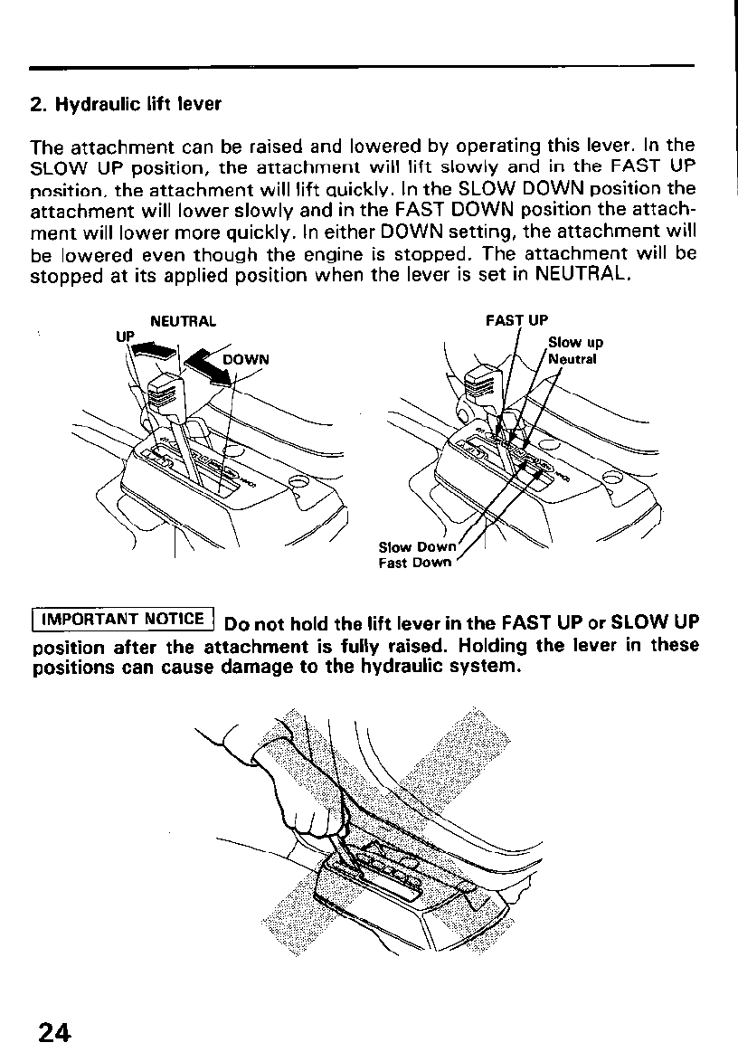
2. Hydraulic lift lever
The attachment can be raised and lowered by operating this lever. In the
SLOW UP position, the attachment will lift slowly and in the FAST UP
position, the attachment will lift quickly. In the SLOW DOWN position the
attachment will lower slowly and in the FAST DOWN position the attach-
ment will lower more quickly. In either DOWN setting, the attachment will
be lowered even though the engine is stopped. The attachment will be
stopped at its applied position when the lever is set in NEUTRAL.
NEUTRAL FAST UP
I IMPORTANT NoTlCE 1 Do not hold the lift lever in the FAST UP or SLOW UP
position after the attachment is fully raised. Holding the lever in these
positions can cause damage to the hydraulic system.
24
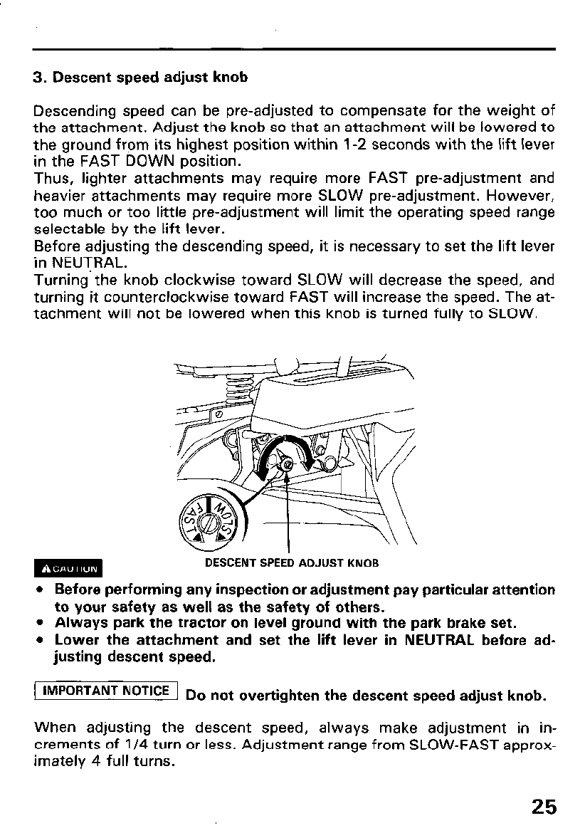
3. Descent speed adjust knob
Descending speed can be pre-adjusted to compensate for the weight of
the attachment. Adjust the knob so that an attachment will be lowered to
the ground from its highest position within l-2 seconds with the lift lever
in the FAST DOWN position.
Thus, lighter attachments may require more FAST pre-adjustment and
heavier attachments may require more SLOW pre-adjustment. However,
too much or too little pre-adjustment will limit the operating speed range
selectable by the lift lever.
Before adjusting the descending speed, it is necessary to set the lift lever
in NEUTRAL.
Turning the knob clockwise toward SLOW will decrease the speed, and
turning it counterclockwise toward FAST will increase the speed. The at-
tachment will not be lowered when this knob is turned fully to SLOW.
w DESCENT SPEED ADJUST KNOB
l Before performing any inspection or adjustment pay particular attention
to your safety as well as the safety of others.
l Always park the tractor on level ground with the park brake set.
l Lower the attachment and set the lift lever in NEUTRAL before ad-
justing descent speed.
1 IMPORTANT NoTKE 1 Do not overtighten the descent speed adjust knob.
When adjusting the descent speed, always make adjustment in in-
crements of l/4 turn or less. Adjustment range from SLOW-FAST approx-
imately 4 full turns.
25
5. PRE-OPERATUON CHECKS
For safe and efficient operation, always perform the pre-operation checks
before using the tractor.
Follow the procedures below and check all of the following items before
each use:
1. Park the tractor on a level surface.
2. Lock the parking brake, set the transmission lever in “N” (Neutral) and
the front and rear P.T.O. levers in the “OFF” positions.
3. Disconnect the spark plug cap and remove the key to prevent acciden-
tal engine start-up.
m If the engine is started accidentally while you are performing
the pre-operation checks, moving parts may cause serious injury.
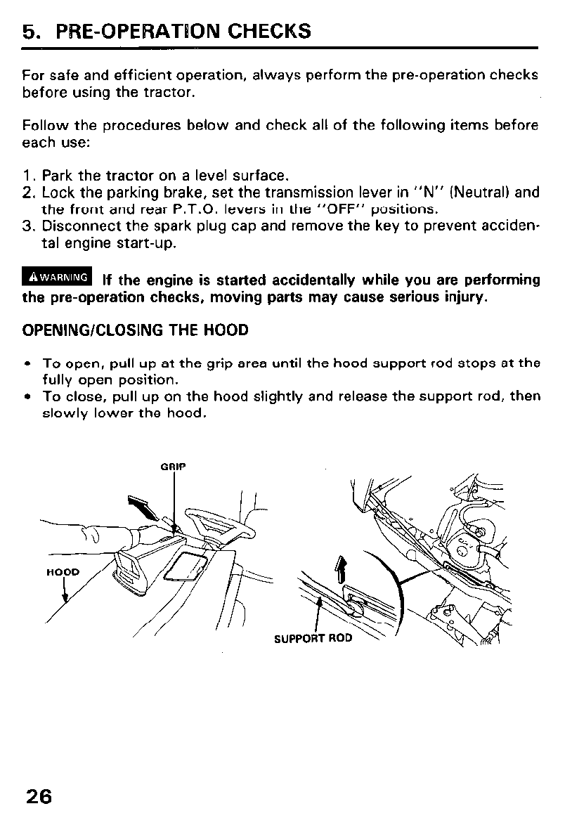
OPENING/CLOSING THE HOOD
l To open, pull up at the grip area until the hood support rod stops at the
fully open position.
l To close, pull up on the hood slightly and release the support rod, then
slowly lower the hood.
GRIP
26
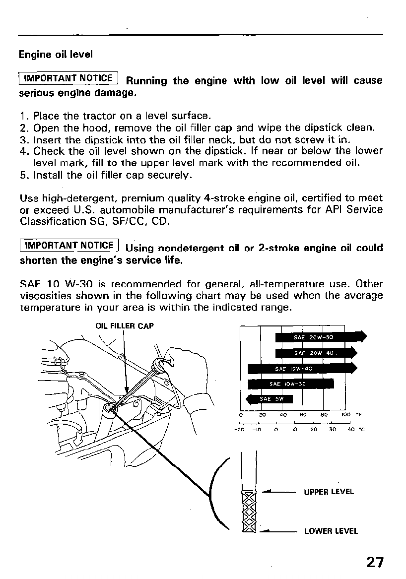
Engine oil level
1 ~~~~~~~~~ NoTlCE 1 Running the engine with low oil level will cause
serious engine damage.
1. Place the tractor on a level surface.
2. Open the hood, remove the oil filler cap and wipe the dipstick clean.
3. Insert the dipstick into the oil filler neck, but do not screw it in.
4. Check the oil level shown on the dipstick. If near or below the lower
level mark, fill to the upper level mark with the recommended oil.
5. Install the oil filler cap securely.
Use high-detergent, premium quality 4-stroke engine oil, certified to meet
or exceed U.S. automobile manufacturer’s requirements for API Service
Classification SG, SF/CC, CD.
1 IMPORTANT NoTKE 1 Using nondetergent oil or 2-stroke engine oil could
shorten the engine’s service life.
SAE 10 W-30 is recommended for general, all-temperature use. Other
viscosities shown in the following chart may be used when the average
temperature in your area is within the indicated range.
OIL FILLER CAP
0 20 40 60 SO 100 *F
-20 -10 0 IO 20 30 40 'C
- UPPER LEVEL
- LOWER LEVEL
27
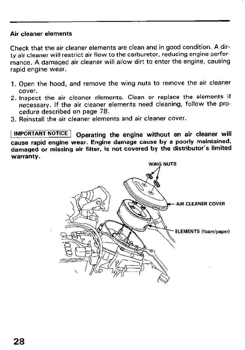
Air cleaner elements
Check that the air cleaner elements are clean and in good condition. A dir-
ty air cleaner will restrict air flow to the carburetor, reducing engine perfor-
mance. A damaged air cleaner will allow dirt to enter the engine, causing
rapid engine wear.
1. Open the hood, and remove the wing nuts to remove the air cleaner
cover.
2. Inspect the air cleaner elements. Clean or replace the elements if
necessary. If the air cleaner elements need cleaning, follow the pro-
cedure described on page 78.
3. Reinstall the air cleaner elements and air cleaner cover.
1 IMPORTANT NOTICE I Operating the engine without an air cleaner will
cause rapid engine wear. Engine damage cause by a poorly maintained,
damaged or missing air filter, is not covered by the distributor’s limited
warranty.
WING NUTS
AIR CLEANER COVER
ELEMENTS (foam/paper)
28
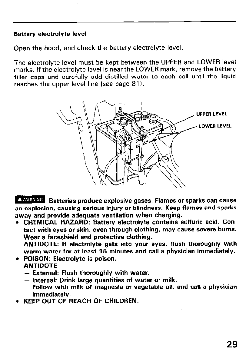
Battery electrolyte level
Open the hood, and check the battery electrolyte level.
The electrolyte level must be kept between the UPPER and LOWER level
marks. If the electrolyte level is near the LOWER mark, remove the battery
filler caps and carefully add distilled water to each cell until the liquid
reaches the upper level line (see page 81).
LOWER LEVEL
m Batteries produce explosive gases. Flames or sparks can cause
an explosion, causing serious injury or blindness. Keep flames and sparks
away and provide adequate ventilation when charging.
l CHEMICAL HAZARD: Battery electrolyte contains sulfuric acid. Con-
tact with eyes or skin, even through clothing, may cause severe burns.
Wear a faceshield and protective clothing.
ANTIDOTE: If electrolyte gets into your eyes, flush thoroughly with
warm water for at least 15 minutes and call a physician immediately.
l POISON: Electrolyte is poison.
ANTIDOTE
- External: Flush thoroughly with water.
- Internal: Drink large quantities of water or milk.
Follow with milk of magnesia or vegetable oil, and call a physician
immediately.
. KEEP OUT OF REACH OF CHILDREN.
29
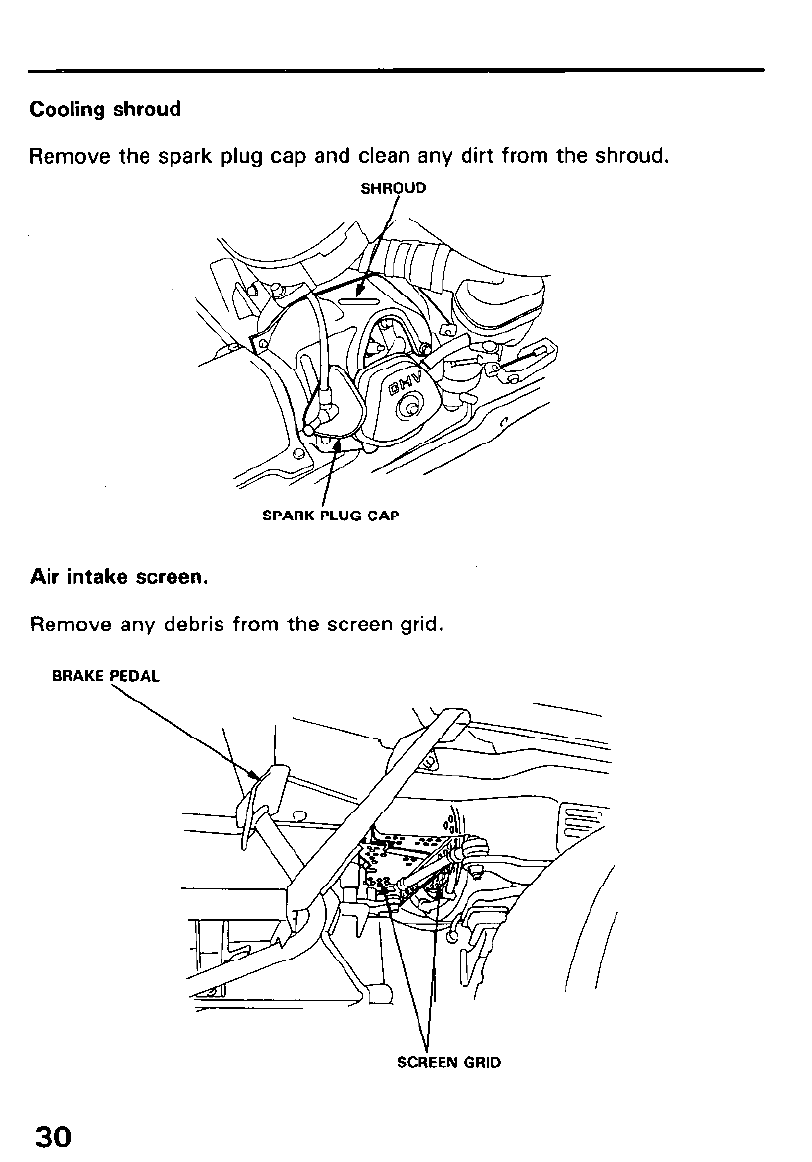
Cooling shroud
Remove the spark plug cap and clean any dirt from the shroud.
SHR?UD
SPARK PLUG CAP
Air intake screen.
Remove any debris from the screen grid.
BRAKE PEDAL
SCdEEN GRID
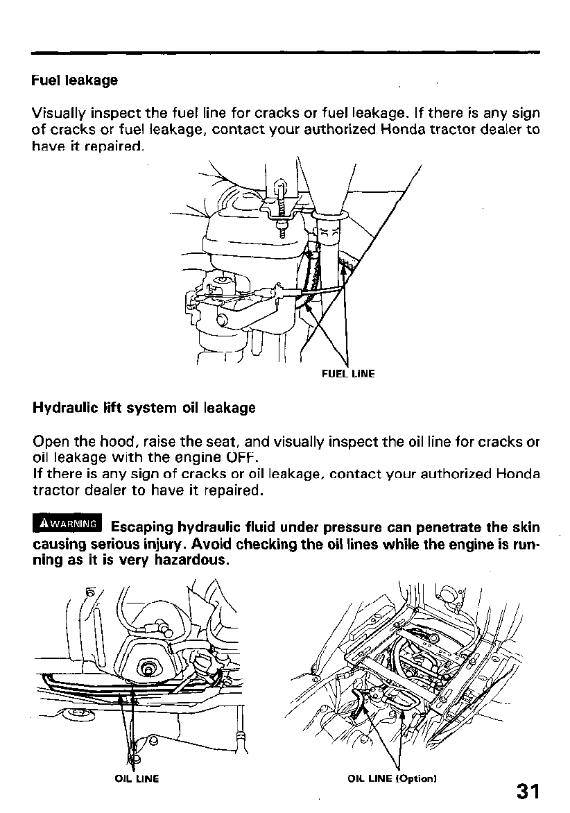
Fuel leakage
Visually inspect the fuel line for cracks or fuel leakage. If there is any sign
of cracks or fuel leakage, contact your authorized Honda tractor dealer to
have it repaired.
FUEL- LINE
Hydraulic lift system oil leakage
Open the hood, raise the seat, and visually inspect the oil line for cracks or
oil leakage with the engine OFF.
If there is any sign of cracks or oil leakage, contact your authorized Honda
tractor dealer to have it repaired.
m Escaping hydraulic fluid under pressure can penetrate the skin
causing serious injury. Avoid checking the oil lines while the engine is run-
ning as it is very hazardous.
OIL-LINE OIL LINE (Option) 31
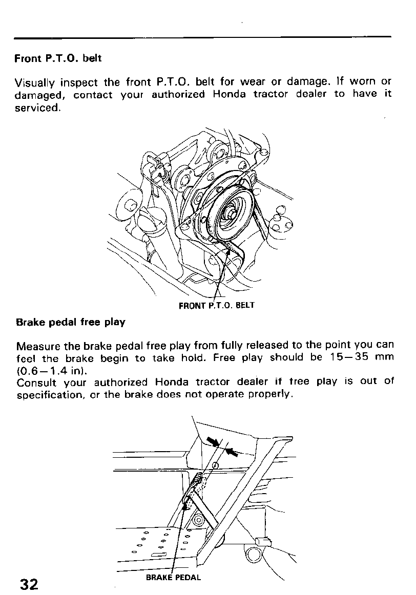
Front P.T.O. belt
Visually inspect the front P.T.O. belt for wear or damage. If worn or
damaged, contact your authorized Honda tractor dealer to have it
serviced.
Brake pedal free play
FRONT d.T.0. BELT
Measure the brake pedal free play from fully released to the point you can
feel the brake begin to take hold. Free play should be 15-35 mm
(0.6- 1.4 in).
Consult your authorized Honda tractor dealer if free play is out of
specification, or the brake does not operate properly.
32 BRAKE’ PEDAL \
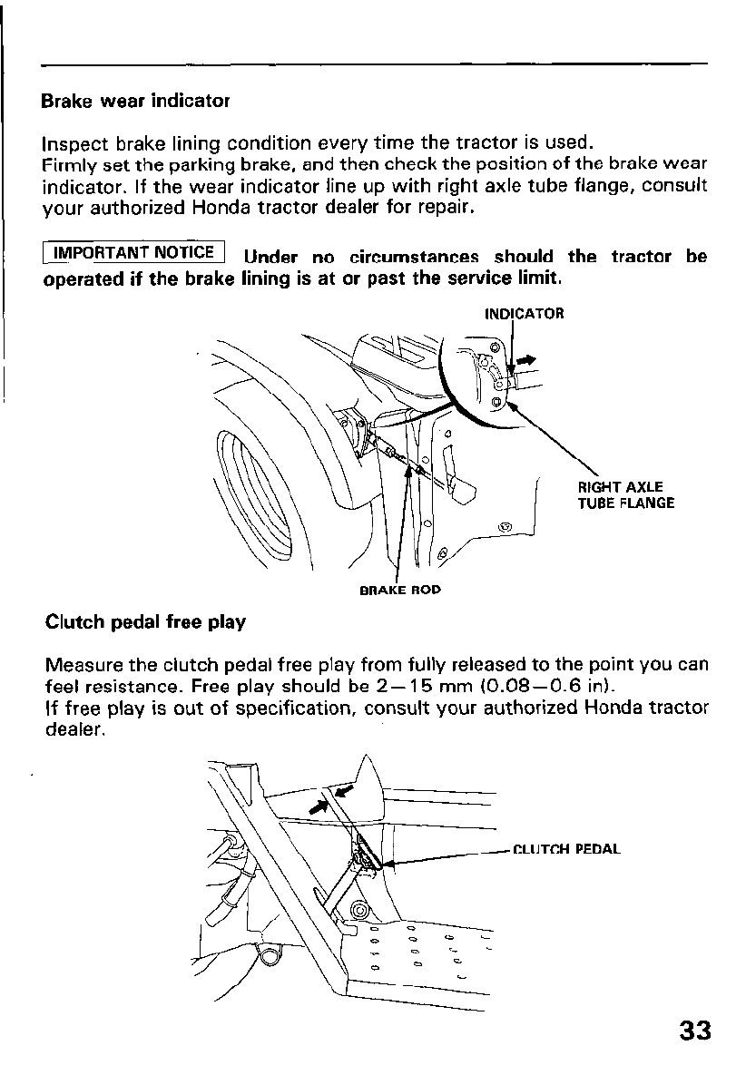
Brake wear indicator
Inspect brake lining condition every time the tractor is used.
Firmly set the parking brake, and then check the position of the brake wear
indicator. If the wear indicator line up with right axle tube flange, consult
your authorized Honda tractor dealer for repair.
IMPORTANT NOTICE 1 Under no circumstances should the tractor be
operated if the brake lining is at or past the service limit.
lNDICATOR
RIGHT AXLE
TUBE FLANGE
BRAiE ROD
Clutch pedal free play
Measure the clutch pedal free play from fully released to the point you can
feel resistance. Free play should be 2- 15 mm (0.08-0.6 in).
If free play is out of specification, consult your authorized Honda tractor
dealer.
CLUTCH PEDAL
33
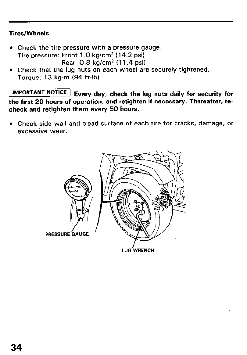
Tires/Wheels
l Check the tire pressure with a pressure gauge.
Tire pressure: Front 1 .O kg/cm2 (14.2 psi)
Rear 0.8 kg/cm* (11.4 psi)
l Check that the lug nuts on each wheel are securely tightened.
Torque: 13 kg-m (94 ft-lb)
1 IMPORTANT NOTICE 1 E
very day, check the lug nuts daily for security for
the first 20 hours of operation, and retighten if necessary. Thereafter, re-
check and retighten them every 50 hours.
l Check side wall and tread surface of each tire for cracks, damage, or
excessive wear.
PRESSURE GAUGE
34
LUG’WRENCH
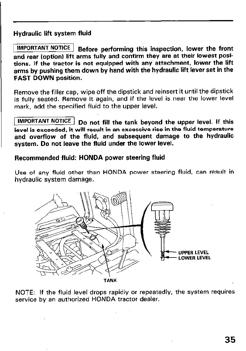
Hydraulic lift system fluid
1 IMPORTANT NOTICE 1 B e ore
f performing this inspection, lower the front
and rear (option) lift arms fully and confirm they are at their lowest posi-
tions. If the tractor is not equipped with any attachment, lower the lift
arms by pushing them down by hand with the hydraulic lift lever set in the
FAST DOWN position.
Remove the filler cap, wipe off the dipstick and reinsert it until the dipstick
is fully seated. Remove it again, and if the level is near the lower level
mark, add the specified fluid to the upper level.
1 IMPORTANT NOTICE ] ,, o not fill the tank beyond the upper level. If this
level is exceeded, it will result in an excessive rise in the fluid temperature
and overflow of the fluid, and subsequent damage to the hydraulic
system. Do not leave the fluid under the lower level.
Recommended fluid: HONDA power steering fluid
Use of any fluid other than HONDA power steering fluid, can result in
hydraulic system damage.
TANK
UPPER LEVEL
LOWER LEVEL
NOTE: If the fluid level drops rapidly or repeatedly, the system requires
service by an authorized HONDA tractor dealer.
35
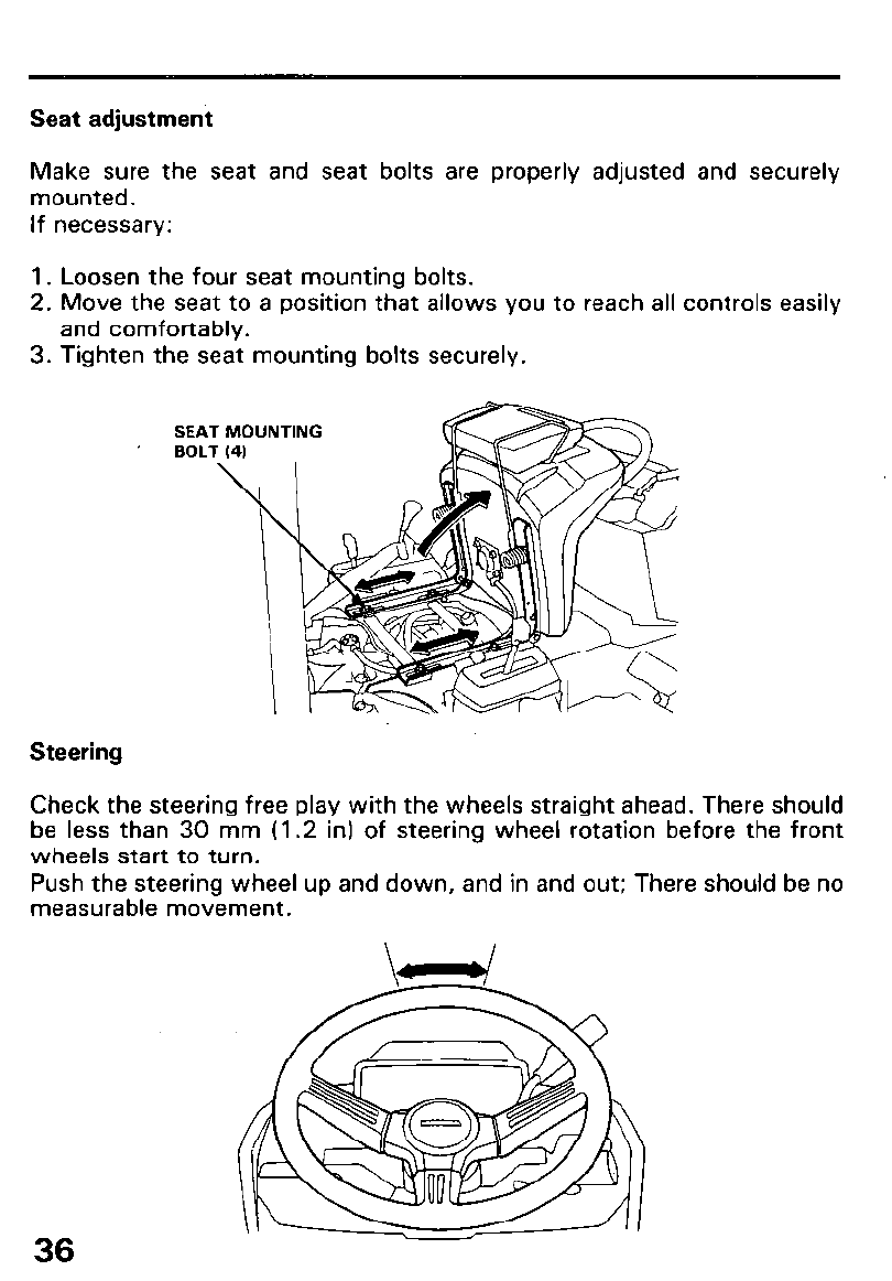
Seat adjustment
Make sure the seat and seat bolts are properly adjusted and securely
mounted.
If necessary:
1. Loosen the four seat mounting bolts.
2. Move the seat to a position that allows you to reach all controls easily
and comfortably.
3. Tighten the seat mounting bolts securely.
SEAT MOUNTING
’ BOLT (4)
Steering
Check the steering free play with the wheels straight ahead. There should
be less than 30 mm (1.2 in) of steering wheel rotation before the front
wheels start to turn.
Push the steering wheel up and down, and in and out; There should be no
measurable movement.
36
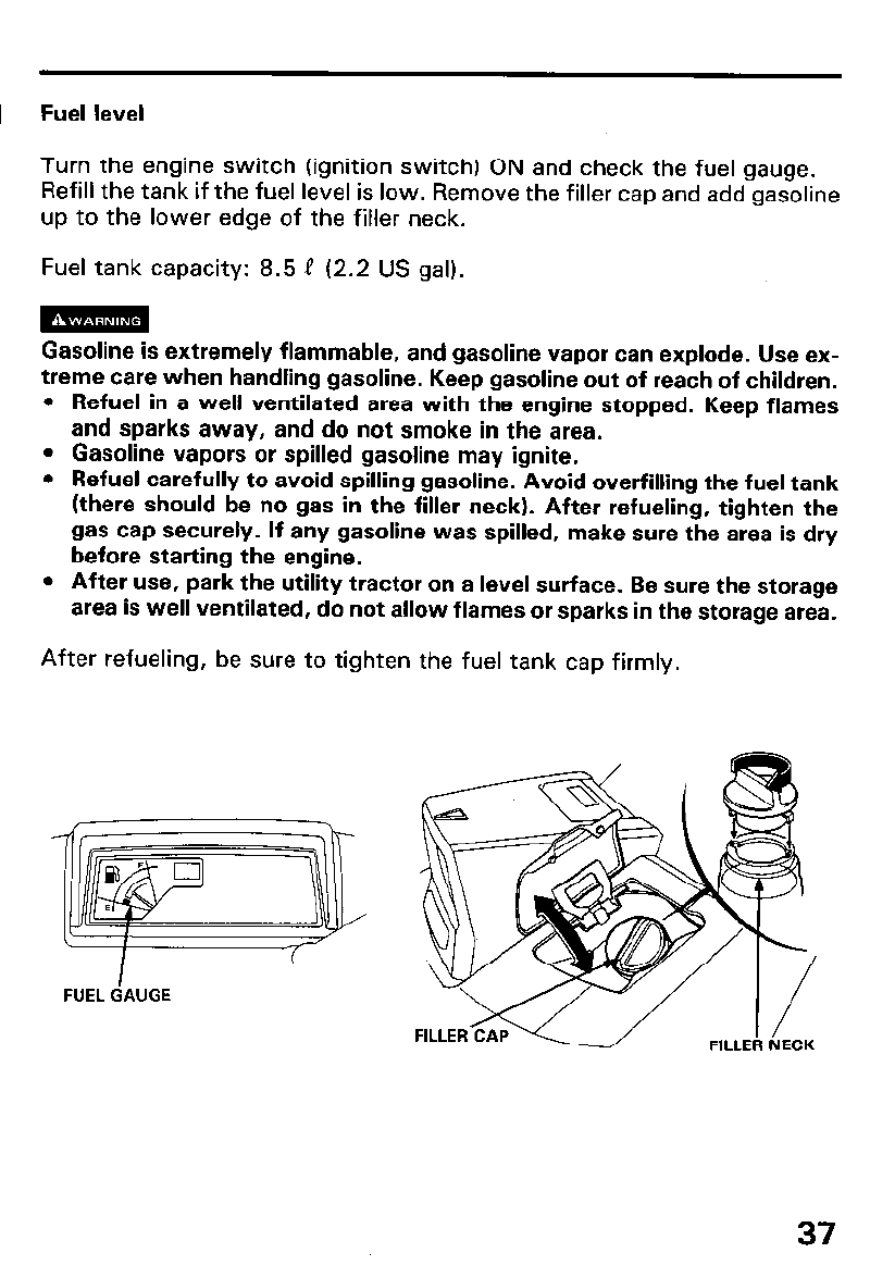
Fuel level
Turn the engine switch (ignition switch) ON and check the fuel gauge.
Refill the tank if the fuel level is low. Remove the filler cap and add gasoline
up to the lower edge of the filler neck.
Fuel tank capacity: 8.5 P (2.2 US gal).
Gasoline is extremely flammable, and gasoline vapor can explode. Use ex-
treme care when handling gasoline. Keep gasoline out of reach of children.
l Refuel in a well ventilated area with the engine stopped. Keep flames
and sparks away, and do not smoke in the area.
l Gasoline vapors or spilled gasoline may ignite.
l Refuel carefully to avoid spilling gasoline. Avoid overfilling the fuel tank
(there should be no gas in the filler neck). After refueling, tighten the
gas cap securely. If any gasoline was spilled, make sure the area is dry
before starting the engine.
l After use, park the utility tractor on a level surface. Be sure the storage
area is well ventilated, do not allow flames or sparks in the storage area.
After refueling, be sure to tighten the fuel tank cap firmly.
FUEL GAUGE
37
Gasoline Recommendation
Pump octane rating: 86 or higher
We recommend the use of unleaded gasoline because it produces fewer
engine and spark plug deposits and extends the exhaust system life.
If “spark knock” (metallic rapping noise) or persistent “pinging” occurs at
a steady engine speed under normal load, change brands of gasoline. If
spark knock or pinging persists, see an authorized Honda tractor dealer.
1 IMPORTANT NOTICE 1 R unning the engine with persistent spark knock or
pinging can cause engine damage.
Running the engine with persistent spark knock or pinging is considered
misuse, and the Distributor’s Limited Warranty does not cover parts
damaged by misuse.
Occasionally you may hear light spark knock while operating under heavy
loads. This is no cause for concern. It simply means your engine is
operating efficiently.
Never use stale or contaminated gasoline or an oil/gasoline mixture. Avoid
getting dirt or water in the fuel tank.
38
GASOLINES CONTAINING ALCOHOL
If you decide to use a gasoline containing alcohol (gasohol), be sure its oc-
tane rating is at least as high as that recommended by Honda (see
Gasoline Recommendation on page 38). There are two types of
“gasohol”: one containing ethanol, and the other containing methanol.
m Using gasohol that contains more than 10% ethanol, or
gasoline containing methanol (methyl or wood alcohol) that does not also
contain cosolvents and corrosion inhibitors for methanol, can cause
serious fuel system damage and poor engine performance.
Never use gasoline containing more than 5% methanol, even if it has
cosolvents and corrosion inhibitors.
Honda cannot endorse the use of gasoline containing methanol since
evidence of its suitability is as yet incomplete.
NOTE: Fuel system damage or engine performance problems resulting
from the use of gasoline that contains alcohol is not covered under the
warranty.
Before buying gasoline from an unfamiliar station, first determine if the
gasoline contains alcohol; if it does, find out the type and percentage of
alcohol used.
NOTE: If you notice any undesirable operating symptoms while using a
gasoline that contains alcohol, or one that you think contains alcohol,
switch to a gasoline that you know does not contain alcohol.
39
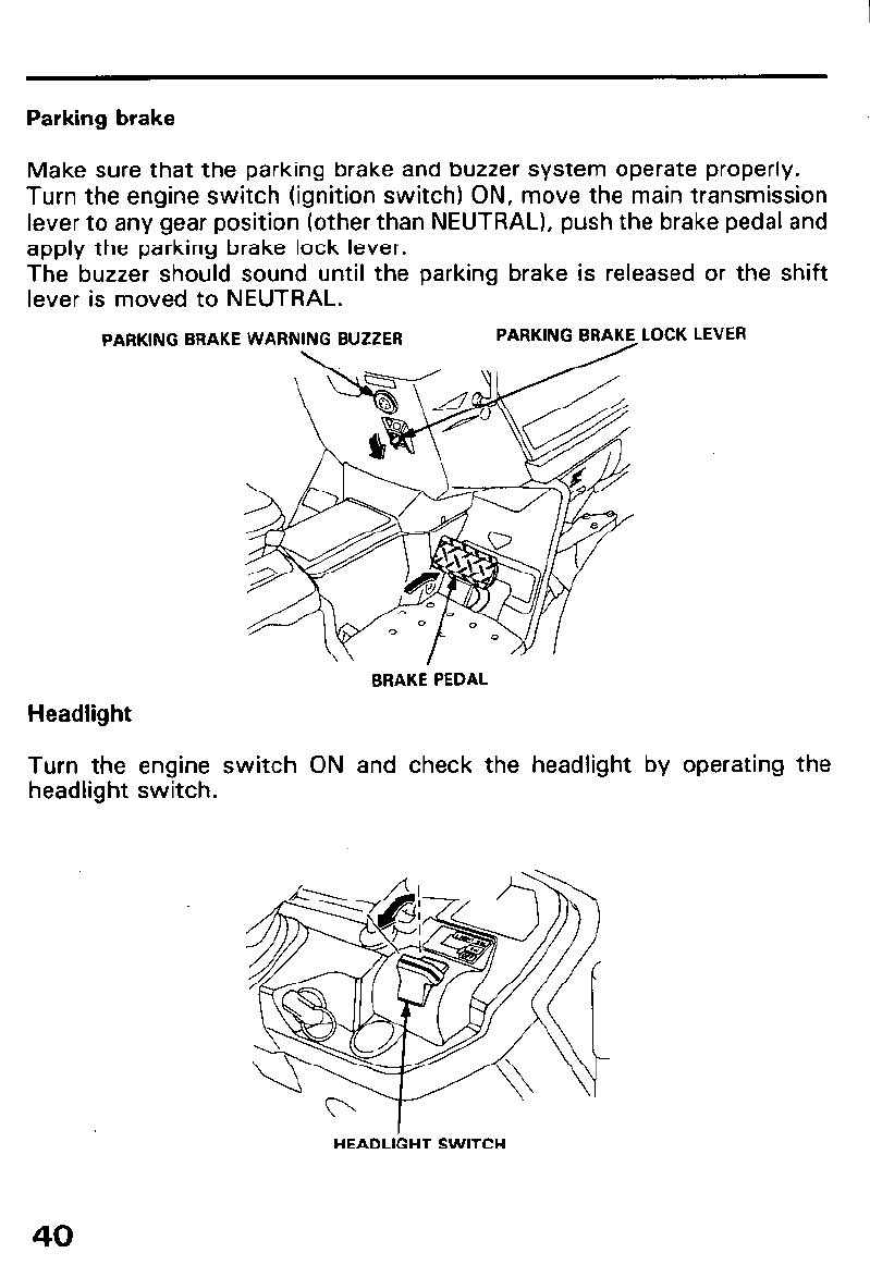
Parking brake
Make sure that the parking brake and buzzer system operate properly.
Turn the engine switch (ignition switch) ON, move the main transmission
lever to any gear position (other than NEUTRAL), push the brake pedal and
apply the parking brake lock lever.
The buzzer should sound until the parking brake is released or the shift
lever is moved to NEUTRAL.
PARKING BRAKE WARN LOCK LEVER
Headlight
BRAKE PEDAL
Turn the engine switch ON and check the headlight by operating the
headlight switch.
HEADLIGHT SWITCH
40
Safety interlock system
m Before inspecting, ensure that the area in front of and behind
the tractor is clear of people, pets and obstacles.
This tractor is equipped with a series of inhibitor switches which prevent
the engine from being started unless the proper operating procedures are
followed. Observe the following procedures to check the inhibitor
switches.
m Do not operate the tractor if there are any abnormalities in the
system, or in the operation of the switches. An accident or severe per-
sonal injury could result.
Consult your authorized Honda tractor dealer.
To check the system, sit in the seat, and lock the parking brake.
To prevent accidental engine start up, be sure to remove the spark plug
cap from the spark plug when performing the inspection procedures 1 to
4.
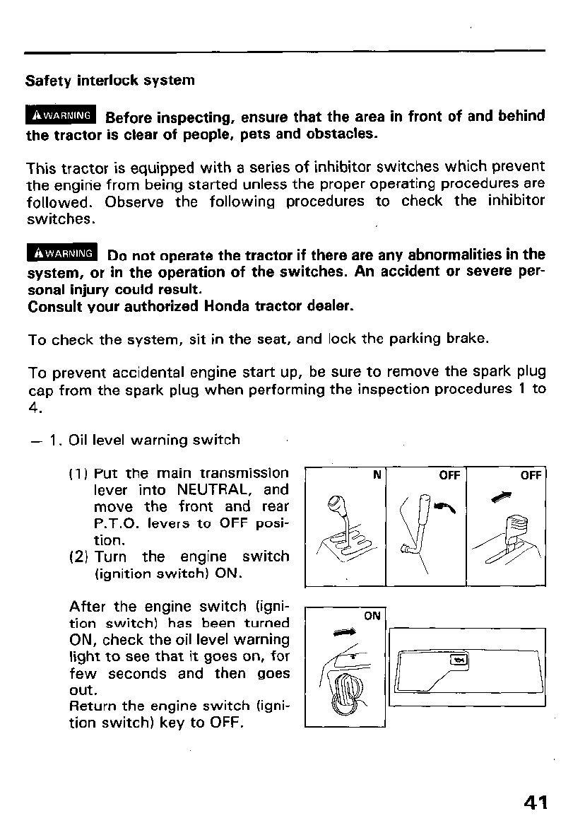
- 1. Oil
(1)
level warning switch
Put the main transmission
lever into NEUTRAL, and
move the front and rear
P.T.O. levers to OFF posi-
tion.
(2) Turn the engine switch
(ignition switch) ON.
After the engine switch (igni-
tion switch) has been turned
ON, check the oil level warning
light to see that it goes on, for
few seconds and then goes
out.
Return the engine switch (igni-
tion switch) key to OFF.
41
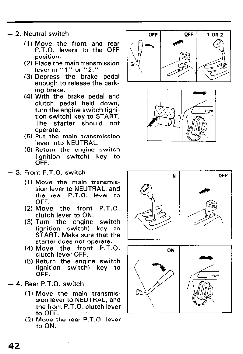
- 2. Neutral switch
(1) Move the front and rear
P.T.O. levers to the OFF
position.
OFF QFF 1 OR2
(2) Place the main transmission
lever in “1” or “2.”
(3) Depress the brake pedal
enough to release the park- .
ing brake.
(4) With the brake pedal and
clutch pedal held down,
turn the engine switch (igni-
tion switch) key to START.
The starter should not
operate.
(5) Put the main transmission
lever into NEUTRAL.
(6) Return the engine switch
(ignition switch) key to
OFF.
- 3. Front P.T.O. switch
(1) Move the main transmis-
sion lever to NEUTRAL, and
the rear P.T.O. lever to
OFF.
(2) Move the front P.T.O.
clutch lever to ON.
(3) Turn the engine switch
(ignition switch) key to
START. Make sure that the
starter does not operate.
(4) Move the front P.T.O.
clutch lever OFF.
(5) Return the engine switch
(ignition switch) key to
OFF.
- 4. Rear P.T.O. switch
(1) Move the main transmis-
sion lever to NEUTRAL, and
the front P.T.O. clutch lever
to OFF.
(2) p;; the rear P.T.O. lever
42
N
&
..A
ON
OFF
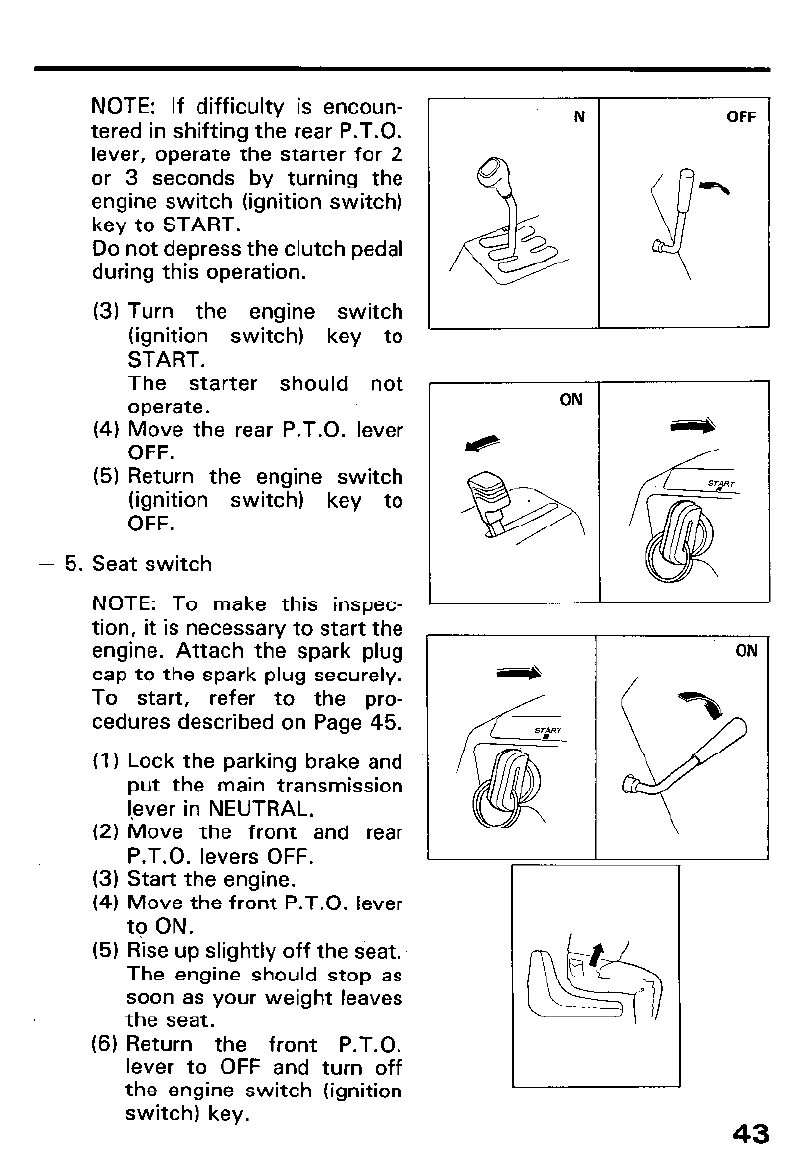
NOTE: If difficulty is encoun-
tered in shifting the rear P.T.O.
lever, operate the starter for 2
or 3 seconds by turning the
engine switch (ignition switch)
key to START.
Do not depress the clutch pedal
during this operation.
(3) Turn the engine switch
(ignition switch) key to
START.
The starter should not
operate.
(4) Move the rear P.T.O. lever
OFF.
(5) Return the engine switch
(ignition switch) key to
OFF.
- 5. Seat switch
NOTE: To make this inspec-
tion, it is necessary to start the
engine. Attach the spark plug
cap to the spark plug securely.
To start, refer to the pro-
cedures described on Page 45.
(1) Lock the parking brake and
put the main transmission
lever in NEUTRAL.
(2) Move the front and rear
P.T.O. levers OFF.
(3) Start the engine.
(4) Move the front P.T.O. lever
to ON.
(5) Rise up slightly off the seat.
The engine should stop as
soon as your weight leaves
the seat.
(6) Return the front P.T.O.
lever to OFF and turn off
the engine switch (ignition
switch) key.
N OFF
ON
ON
43
Hydraulic lift system
NOTE:
l To make this inspection, it is necessary to start the engine; refer to the
procedures described on Page 45.
l This inspection should be made with an attachment mounted on the
tractor.
l The check procedure is the same for the front or rear attachment lifts.
Check either, by selecting the appropriate hydraulic cylinder selector
lever position.
(1) Start the engine.
(2) Set the hydraulic cylinder selector lever in FRONT or REAR (option).
(3) Move the lift lever to FAST or SLOW UP position, then release your
hand from the lever.
Check that the lift lever returns to NEUTRAL.
(4) Check that the attachment is lowered when the lift lever is moved
to the DOWN or SLOW DOWN position.
(5) Check the descent speed and adjust descent speed if necessary,
see page 25.
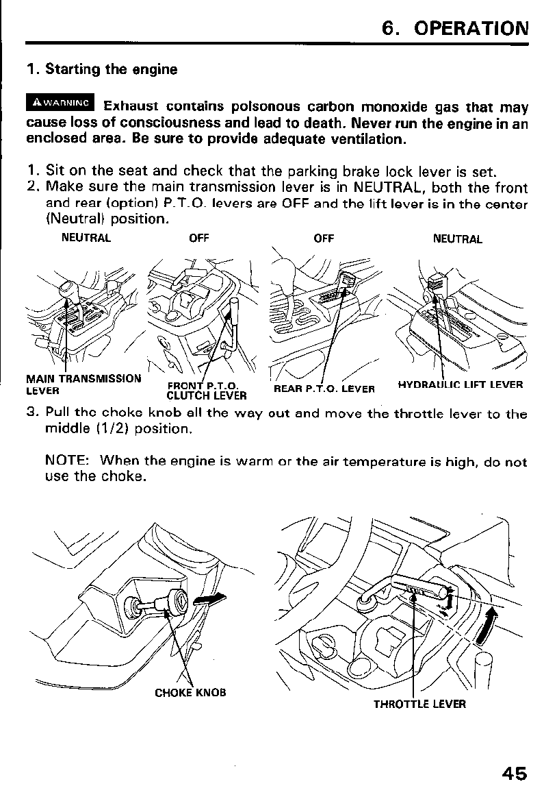
6. OPERATION
1. Starting the engine
m Exhaust contains poisonous carbon monoxide gas that may
cause loss of consciousness and lead to death. Never run the engine in ai
enclosed area. Be sure to provide adequate ventilation.
1. Sit on the seat and check that the parking brake lock lever is set.
2. Make sure the main transmission lever is in NEUTRAL, both the front
and rear (option) P.T.O. levers are OFF and the lift lever is in the center
(Neutral) position.
NEUTRAL OFF OFF NEUTRAL
\
3. Pull the choke knob all the way out and move the throttle lever to the
middle (l/2) position.
NOTE: When the engine is warm or the air temperature is high, do not
use the choke.
CHOKE KNOB THROTTLE LEVER
45
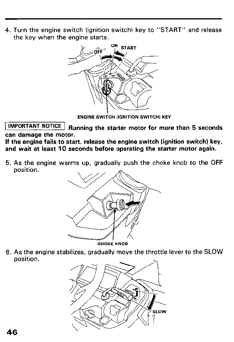
4. Turn the engine switch (ignition switch) key to “START” and release
the key when the engine starts.
ENGINE SWITCH (IGNITION SWITCH1 KEY
[ IMPORTANT NOTICE 1 R unning the starter motor for more than 5 seconds
can damage the motor.
If the engine fails to start, release the engine switch (ignition switch) key,
and wait at least 10 seconds before operating the starter motor again.
5. As the engine warms up, gradually push the choke knob to the OFF
position.
6. As the engine stabilizes, gradually move the throttle lever to the SLOW
CHOKE KNOB
position.
46
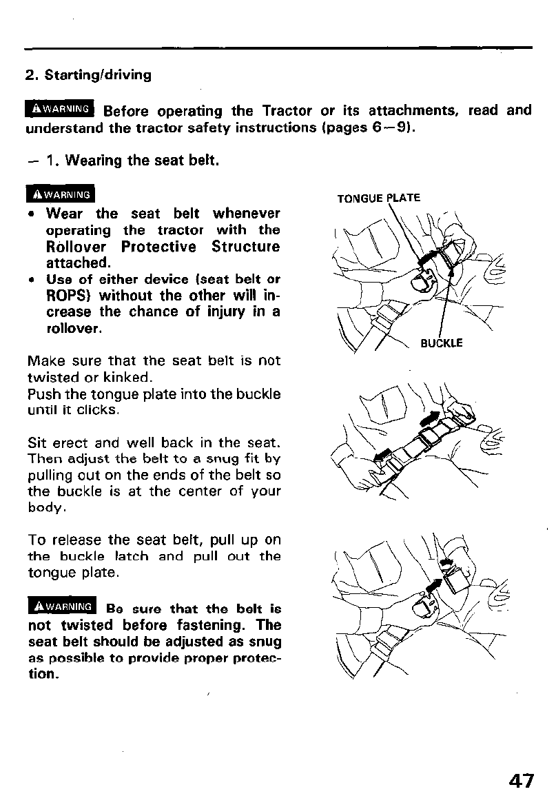
2. Starting/driving
m Before operating the Tractor or its attachments, read and
understand the tractor safety instructions (pages 6-9).
- 1. Wearing the seat belt.
m
Wear the seat belt whenever
operating the tractor with the
Rollover Protective Structure
attached.
Use of either device (seat belt or
ROPS) without the other will in-
crease the chance of injury in a
rollover.
Make sure that the seat belt is not
twisted or kinked.
Push the tongue plate into the buckle
until it clicks.
Sit erect and well back in the seat.
Then adjust the belt to a snug fit by
pulling out on the ends of the belt so
the buckle is at the center of your
body.
To release the seat belt, pull up on
the buckle latch and pull out the
tongue plate.
not twisted before fastening. The
seat belt should be adjusted as snug
as possible to provide proper protec-
tion.
TONGUE PLATE
47
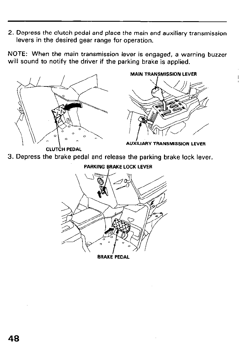
2. Depress the clutch pedal and place the main and auxiliary transmission
levers in the desired gear range for operation.
NOTE: When the main transmission lever is engaged, a warning buzzer
will sound to notify the driver if the parking brake is applied.
MAIN TRANSMISSION LEVER
AUXlLldRY TRANSMISSION LEVER
CLUTCH PEDAL
3. Depress the brake pedal and release the parking brake lock lever.
PARKING LjRAKE LOCK LEVER
BRAKE PEDAL
48
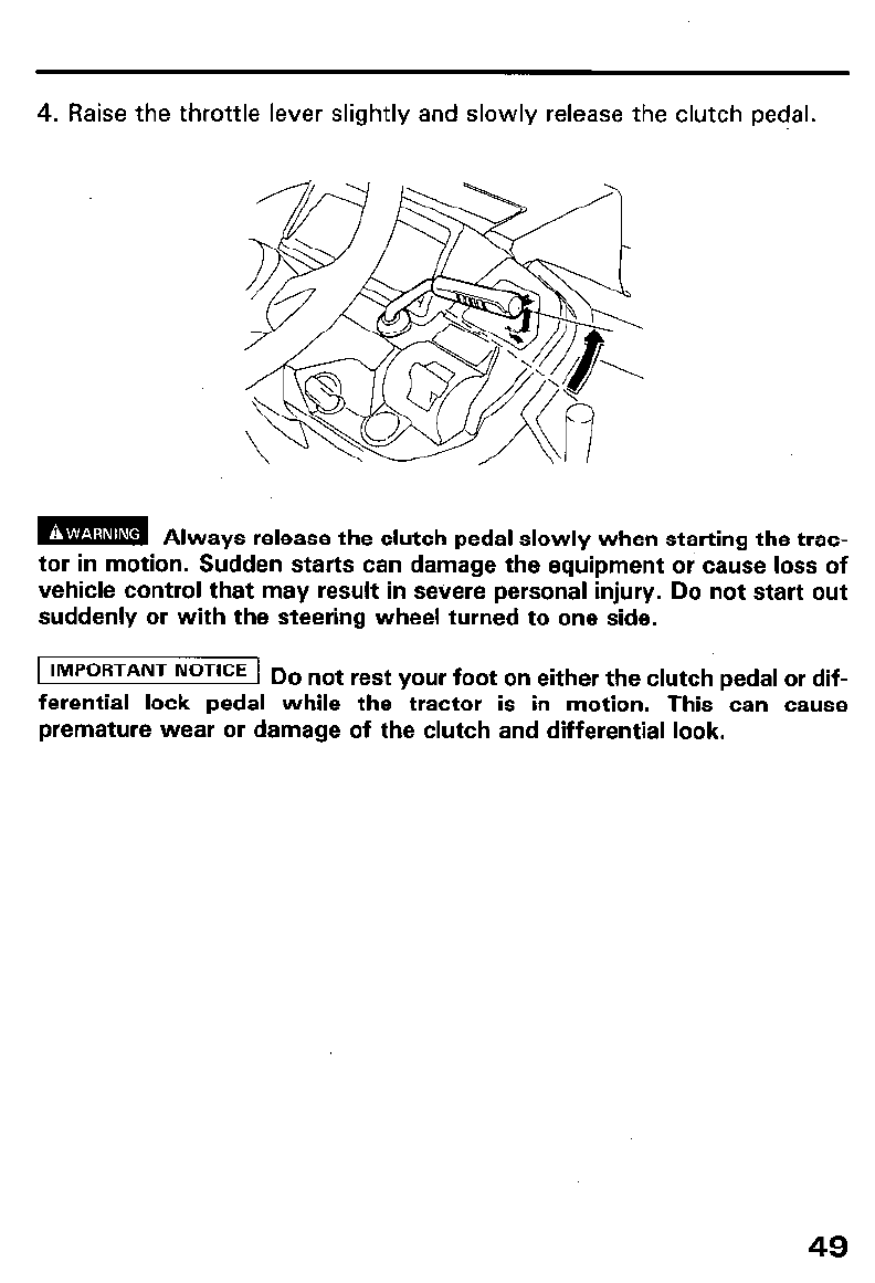
4. Raise the throttle lever slightly and slowly release the clutch pedal.
m Always release the clutch pedal slowly when starting the trac-
tor in motion. Sudden starts can damage the equipment or cause loss of
vehicle control that may result in severe personal injury. Do not start out
suddenly or with the steering wheel turned to one side.
1 IMPORTANT NOTICE 1
D
o not rest your foot on either the clutch pedal or dif-
ferential lock pedal while the tractor is in motion. This can cause
premature wear or damage of the clutch and differential look.
49
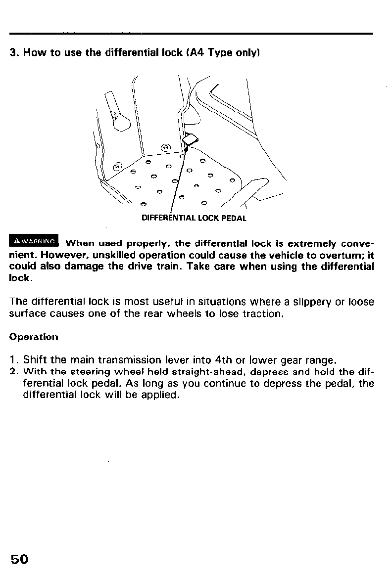
3. How to use the differential lock (A4 Type only)
DIFFERiNTIAL LOCK PEDAL
m When used properly, the differential lock is extremelv conve-
. . _
nient. However, unskilled operation could cause the vehicle to overturn; it
could also damage the drive train. Take care when using the differential
lock.
The differential lock is most useful in situations where a slippery or loose
surface causes one of the rear wheels to lose traction.
Operation
1. Shift the main transmission lever into 4th or lower gear range.
2. With the steering wheel held straight-ahead, depress and hold the dif-
ferential lock pedal. As long as you continue to depress the pedal, the
differential lock will be applied.
50
3. To release the differential lock, remove your foot from the lock pedal,
bring the tractor to a full stop, shift the main transmission from FOR-
WARD to REVERSE or vice versa, and drive a short distance.
m The differential lock must be released before operating the
tractor on hard surfaces or slopes, or while turning. Otherwise the tractor
may overturn, causing severe personel injury.
To avoid damage to transmission mechanism.
l Do not apply the differential lock while the wheels are turning.
l Do not rest your foot on the differential lock pedal unless you want to
engage the differential lock.
l Do not apply the brake and the differential lock at the same time.
l Check that the differential lock has been released after you have finish-
ed using it.
l Do not apply the differential lock while driving at high speed.
l Do not apply the differential lock on a hard packed surface.
51
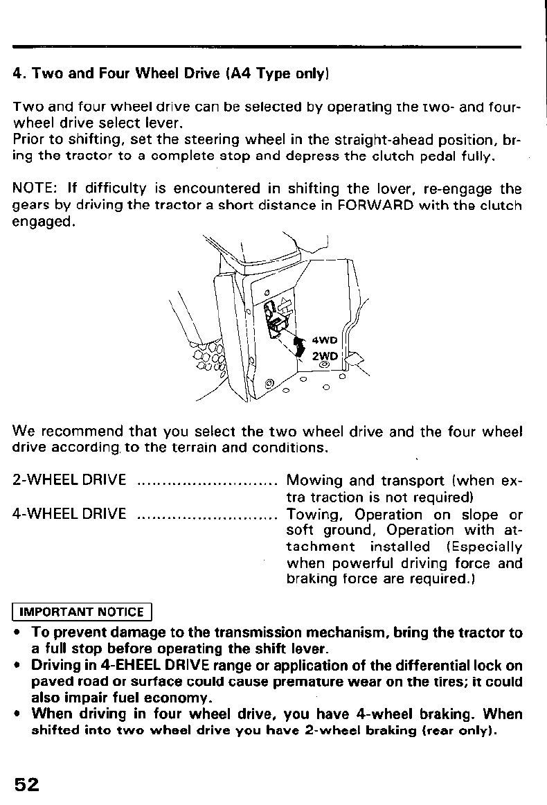
4. Two and Four Wheel Drive (A4 Type only)
Two and four wheel drive can be selected by operating the two- and four-
wheel drive select lever.
Prior to shifting, set the steering wheel in the straight-ahead position, br-
ing the tractor to a complete stop and depress the clutch pedal fully.
NOTE: If difficulty is encountered in shifting the lover, re-engage the
gears by driving the tractor a short distance in FORWARD with the clutch
engaged.
We recommend that you select the two wheel drive and the four wheel
drive according, to the terrain and conditions.
2-WHEEL DRIVE . . . . . . . . . . . . . . . . . . . . . . . . . . . . Mowing and transport (when ex-
tra traction is not required)
4-WHEEL DRIVE . . . . . . . . . . . . . . . . . . . . . . . . . . . . Towing, Operation on slope or
soft ground, Operation with at-
tachment installed (Especially
when powerful driving force and
braking force are required.)
1 IMPORTANT NOTICE 1
l To prevent damage to the transmission mechanism, bring the tractor to
a full stop before operating the shift lever.
l Driving in 4-EHEEL DRIVE range or application of the differential lock on
paved road or surface could cause premature wear on the tires; it could
also impair fuel economy.
l When driving in four wheel drive, you have 4-wheel braking. When
shifted into two wheel drive you have 2-wheel braking (rear only).
52
5. Turning
This tractor has Four Wheel Steering, read the following information
carefully.
m Turning the tractor at excessive speed especially on uneven
terrain can cause the tractor to tip over and you can be injured. Slow down
before turning.
To prevent accidental tip over:
l Never make abrupt starts while the wheels are turned.
l Slow down before making sharp and/or hard turns.
l Avoid sharp turns in rutty or uneven terrain.
l Engaging the differential lock while making sharp turns can cause you
to lose steering control.
l Be sure- to raise ground engaging attachments (rotary tillers, disk har-
rows, moldboard plows, etc.), before executing sharp turns. If the at-
tachment is not raised, you can damage the tractor and/or the
attachment. ,
1 IMPORTANT NOTICE 1
Rear attachments swing out in a larger are than the tractor, and can
strike nearby objects.
Use care when turning the tractor near a wall or other obstructions
when a rear mounted attachment is being used. 4-wheel steering
allows the tractor to turn in a very small radius.
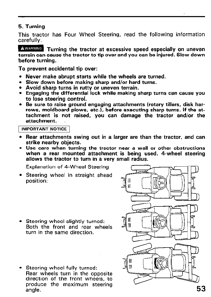
Explanation of 4-Wheel Steering
Steering wheel in straight ahead
position:
Steering wheel slightly turned:
Both the front and rear wheels
turn in the same direction.
Steering wheel fully turned:
Rear wheels turn in the opposite
direction of the front wheels, to
produce the maximum steering
angle.
6. ATTACHMENT LIMITATIONS
Use of Honda attachments is recommended. If an attachment exceeds the
limits shown below or it is not suited to H5013, or if the counterweights
used do not conform to the sizes and weights specified in “Counterweight
Table”, they may not only endanger operators or equipment but also pre-
vent you from taking the fullest advantage of your tractor.
Never use attachments which exceed sizes and weights specified.
Never use counterweights other than those specified in Counterweight
Table.
Any malfunction or damage to the tractor is unwarrantable if it is the con-
sequence of use of attachments not specified or recommended by Honda.
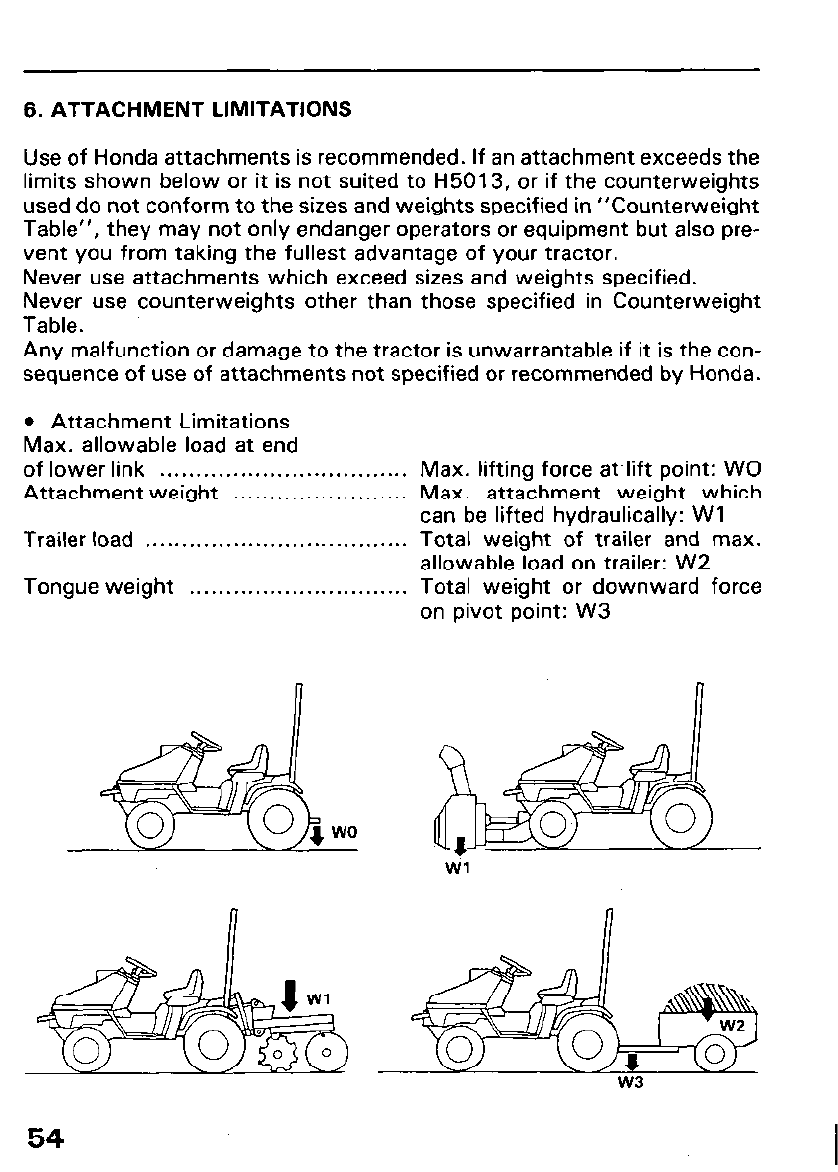
l Attachment Limitations
Max. allowable load at end
of lower link . . . . . . . . . . . . . . . . . . . . . . . . . . . . . . . . . . Max. lifting force atlift point: WO
Attachment weight . . . . . . . . . . . . . . . . . . . . . . . . Max. attachment weight which
can be lifted hydraulically: Wl
Trailer load . . . . . . . . . . . . . . . . . . . . . . . . . . . . . . . . . . . . Total weight of trailer and max.
allowable load on trailer: W2
Tongue weight . . . . . . . . . . . . . . . . . . . . . . . . . . . . . . Total weight or downward force
on pivot point: W3
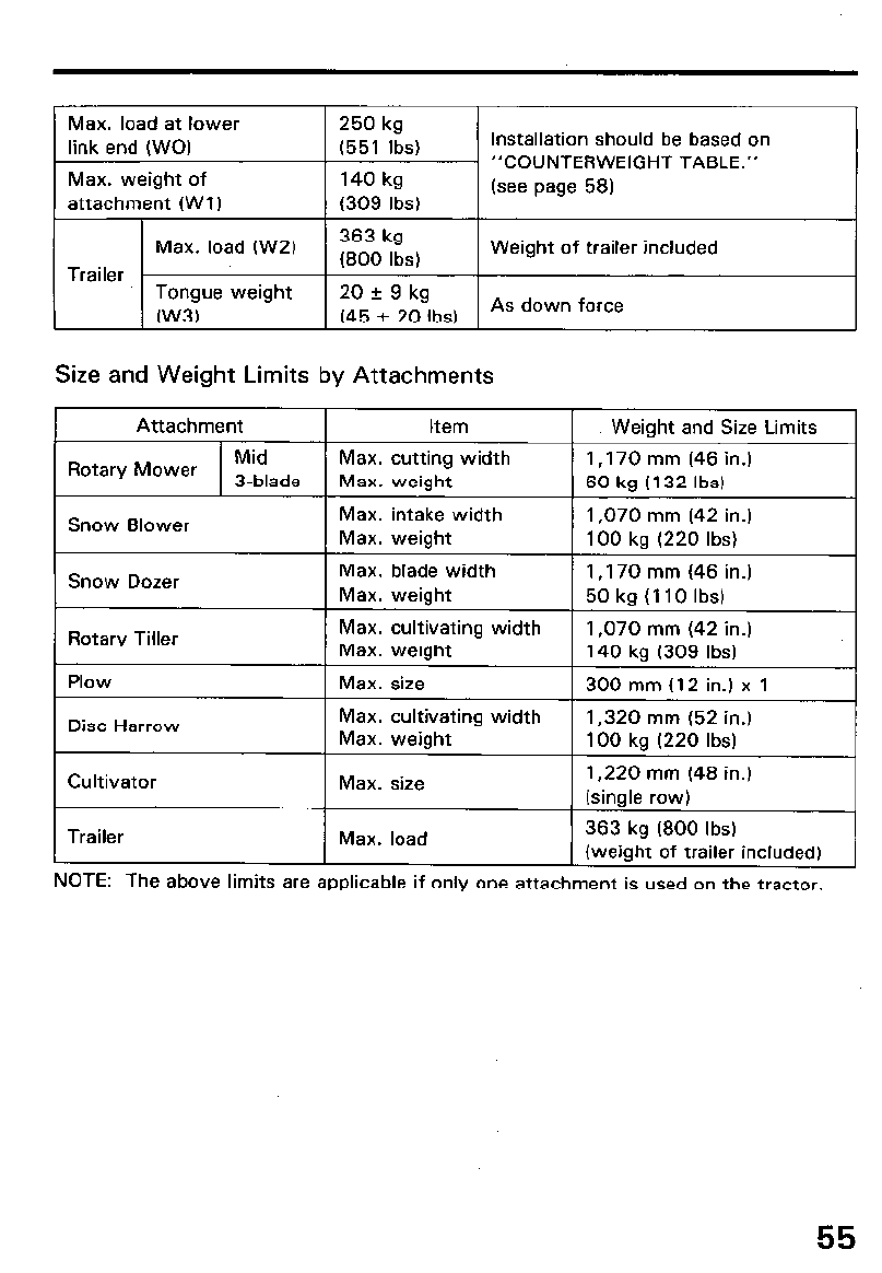
Max. load at lower 250 kg
link end (WO) (551 Ibs)
Max. weight of 140 kg
attachment (Wl) (309 Ibs)
Installation should be based on
“COUNTERWEIGHT TABLE.”
(see page 58)
Max. load (W2) 363 kg Weight of trailer included
Trailer (800 Ibs)
Tongue weight 20 k 9 kg
(W3) (45 f 20 Ibs) As down force
Size and Weight Limits by Attachments
Attachment Item 1 Weight and Size Limits
Rotary Mower Mid Max. cutting width 1 ,I 70 mm (46 in.)
3-blade Max. weight 60 kg (I 32 Ibs)
Snow Blower Max. intake width 1,070 mm (42 in.)
Max. weight 100 kg (220 Ibs)
Snow Dozer Max. blade width 1 ,170 mm (46 in.)
Max. weight 50 kg (110 Ibs)
Rotary Tiller Max. cultivating width 1,070 mm (42 in.)
Max. weight 140 kg (309 Ibs)
Plow Max. size 300 mm (12 in.) x 1
Disc Harrow Max. cultivating width 1,320 mm (52 in.)
Max. weight 100 kg (220 Ibs)
Cultivator Max. size 1,220 mm (48 in.)
(single row)
Trailer Max. load 363 kg (800 Ibs)
(weight of trailer included)
NOTE: The above limits are applicable if only one attachment is used on the tractor.
55
l Towing
l Never attempt to tow anything without a trailer hitch. Failure to use a
proper hitch could cause the tractor to overturn resulting in severe per-
sonal injury or equipment damage.
l Never allow anyone to ride in the trailer.
l Traveling and turning at high speeds while towing a trailer or other at-
tachment is dangerous. Use 1st gear when towing a trailer or attach-
ment over rough ground.
l Avoid sudden starts and stops while towing. The momentum of the
trailer or attachment could cause loss of control resulting in an accident
and severe personal injury or equipment damage.
l The weight of a trailer increases stopping distances; use extra care,
especially when operating on a slope.
Use only those attachments which are designed for the use with this vehi-
cle (Category 0). If you have any questions or doubts about the suitability
of any other attachments, consult your authorized Honda tractor dealer.
[ IMPORTANT NOTICE ] Th e removal of any rear attachment is necessary
when using the draw plate for towing. If the rear attachment is not remov-
ed, damage to the tractor and/or the attachments can occur.
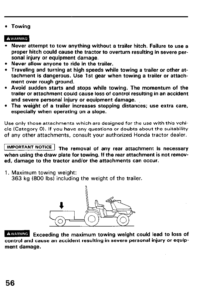
1. Maximum towing weight:
363 kg (800 Ibs) including the weight of the trailer.
m Exceeding the maximum towing weight could lead to loss of
control and cause an accident resulting in severe personal injury or equip-
ment damage.
56
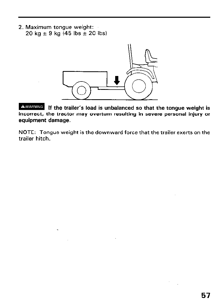
2. Maximum tongue weight:
20 kg + 9 kg (45 Ibs + 20 Ibs)
m If the trailer’s load is unbalanced so that the tongue weight is
incorrect, the tractor may overturn resulting in severe personal injury or
equipment damage.
NOTE: Tongue weight is the downward force that the trailer exerts on the
trailer hitch.
57
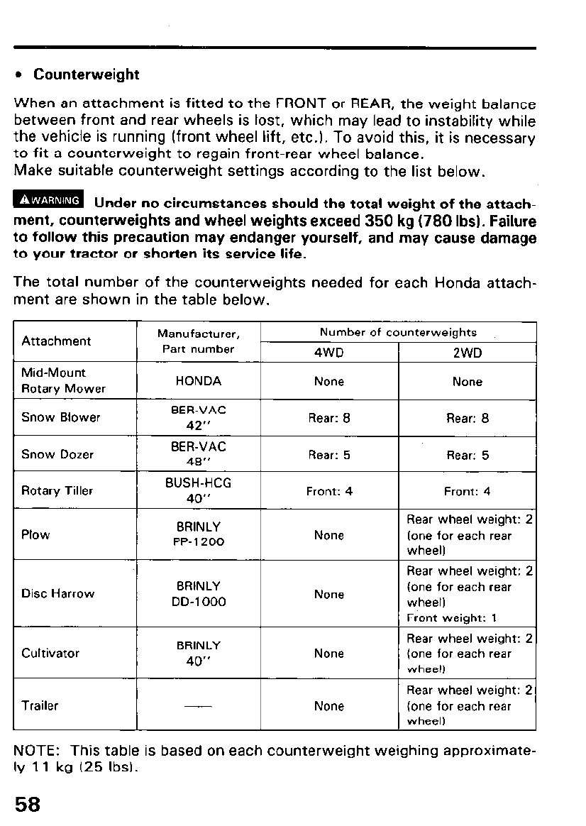
l Counterweight
When an attachment is fitted to the FRONT or REAR, the weight balance
between front and rear wheels is lost, which may lead to instability while
the vehicle is running (front wheel lift, etc.). To avoid this, it is necessary
to fit a counterweight to regain front-rear wheel balance.
Make suitable counterweight settings according to the list below.
m Under no circumstances should the total weight of the attach-
ment, counterweights and wheel weights exceed 350 kg-(780 Ibs). Failure
to follow this precaution may endanger yourself, and may cause damage
to your tractor or shorten its service life.
The total number of the counterweights needed for each Honda attach-
ment are shown in the table below.
Mid-Mount
Rotary Mower
Snow Blower
HONDA
BER-VAC
42”
None
Rear: 8
c- ---- T)ozer I
BER-VAC
48” I Rear: 5
3”OW L
I I
Rotary Tiller
Plow
BUSH-HCG
40”
BRINLY
PP-1200
Front: 4
None
Disc Harrow BRINLY
DD-1000 None
Attachment Manufacturer,
Part number
Number of counterweights
4WD 2WDI
Trailer
I
None
None I
I
Rear: 8 I
Rear: 5 I
Front: 4 I
Rear wheel weight: 2
(one for each rear
wheel)
------I
Rear wheel weight: 2
(one for each rear
wheel)
Front weight: 1
Rear wheel weight: 2
(one for each rear
------I
wheel)
Rear wheel weight: 2
(one for each rear
wheel)
NOTE: This table is based on each counterweight weighing approximate-
ly 11 kg (25 Ibs).
58
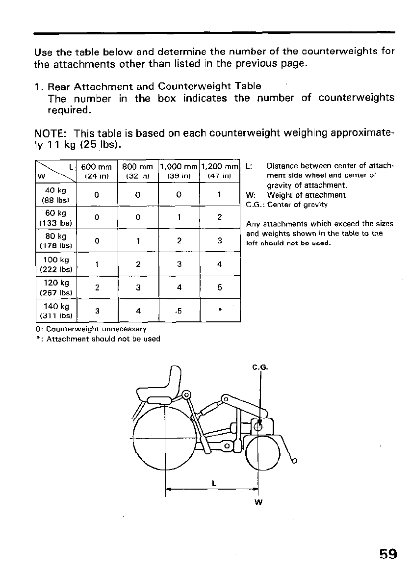
Use the table below and determine the number of the counterweights for
the attachments other than listed in the previous page.
1. Rear Attachment and Counterweight Table
The number in the box indicates the number of counterweights
required.
NOTE: This table is based on each counterweight weighing approximate-
ly 11 kg (25 Ibs).
L: Distance between center of attach-
ment side wheel and center of
gravity of attachment.
w: Weight of attachment
C.G.: Center of gravity
Any attachments which exceed the sizes
and weights shown in the table to the
left should not be used.
0: Counterweight unnecessary
l : Attachment should not be used
59
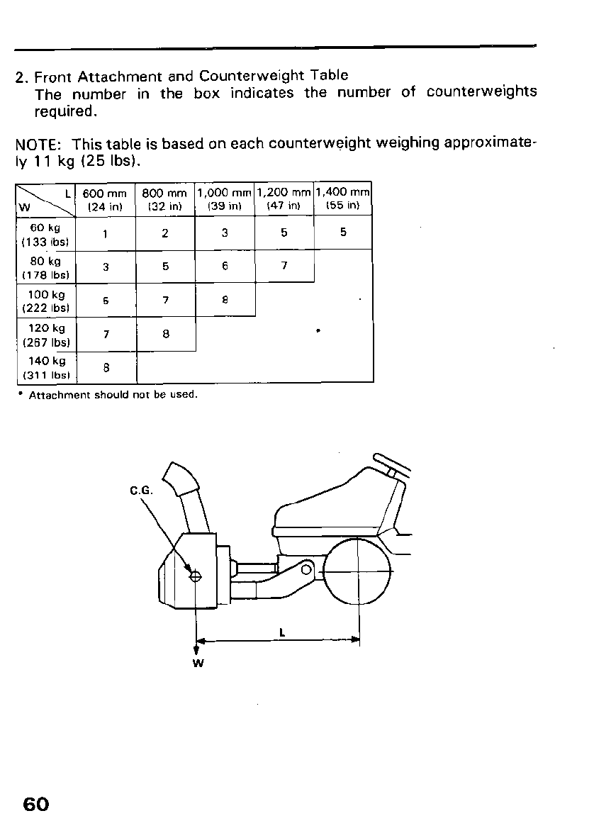
2. Front Attachment and Counterweight Table
The number in the box indicates the number of counterweights
required.
NOTE: This table is based on each counterweight weighing approximate-
ly 11 kg (25 Ibs).
* Attachment should not be used.
C.G.
\
60
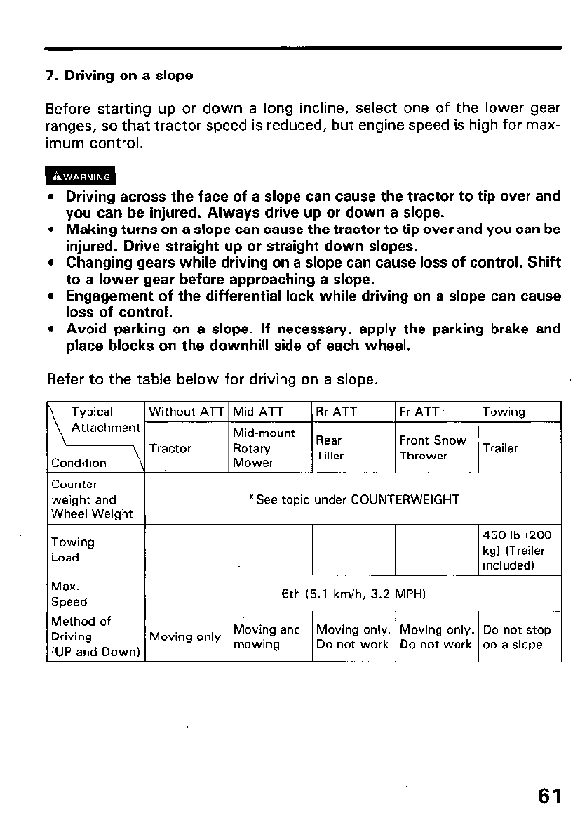
7. Driving on a slope
Before starting up or down a long incline, select one of the lower gear
ranges, so that tractor speed is reduced, but engine speed is high for max-
imum control.
l Driving across the face of a slope can cause the tractor to tip over and
you can be injured. Always drive up or down a slope.
l Making turns on a slope can cause the tractor to tip over and you can be
injured. Drive straight up or straight down slopes.
l Changing gears while driving on a slope can cause loss of control. Shift
to a lower gear before approaching a slope.
l Engagement of the differential lock while driving on a slope can cause
loss of control.
l Avoid parking on a slope. If necessary, apply the parking brake and
place blocks on the downhill side of each wheel.
Refer to the table below for driving on a slope.
Typical Without ATT Mid ATT Rr ATT Fr ATT Towing
Attachment Mid-mount
Tractor Rotary Rear Front Snow Trailer
Condition Mower Tiller Thrower
Counter-
weight and *See topic under COUNTERWEIGHT
Wheel Weight
Towing 450 lb (200
Load kg) (Trailer
included)
Max.
Speed 6th (5.1 km/h, 3.2 MPH)
Method of
Driving Moving only Moving and Moving only. Moving only. Do not stop
(UP and Down) mowing Do not work Do not work on a slope
61
UPHILL STARTING PROCEDURE
If possible avoid stopping the tractor while driving uphill. If it is necessary
to stop on a hill, follow the special procedure below when restarting:
l If this procedure is not followed when restarting on an uphill slope the
tractor may roll backwards during clutch engagement, and this could
cause it to tip over resulting in severe personal injury.
l Abruptly applying the brake pedal while the tractor is rolling backwards
down a slope may cause the tractor to tip over.
- 1. Depress the brake pedal and hold it down.
- 2. Move the throttle lever to “FAST” position.
- 3. Depress the clutch pedal and then move the transmission lever to 1 st
gear position.
- 4. Release the clutch pedal first, then release the brake pedal.
m If the brake pedal is released before the clutch pedal, the trac-
tor may go back down. Never make hard braking. It may cause the tractor
to tip over.
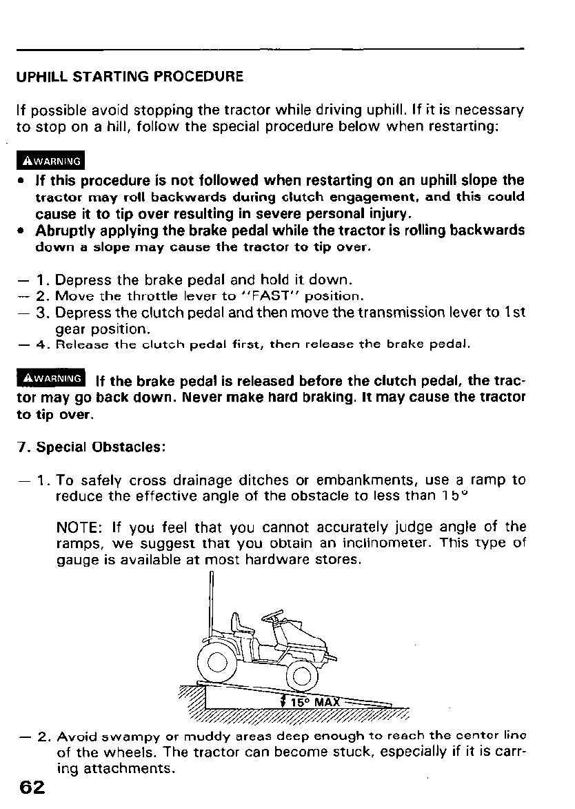
7. Special Obstacles:
- 1. To safely cross drainage ditches or embankments, use a ramp to
reduce the effective angle of the obstacle to less than 15’
NOTE: If you feel that you cannot accurately judge angle of the
ramps, we suggest that you obtain an inclinometer. This type of
gauge is available at most hardware stores.
- 2. Avoid swampy or muddy areas deep enough to reach the center line
of the wheels. The tractor can become stuck, especially if it is carr-
ing attachments.
62
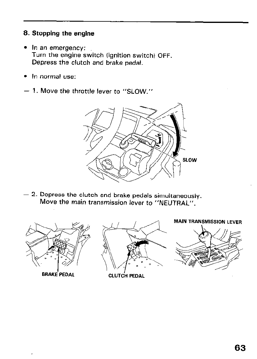
8. Stopping the engine
l In an emergency:
Turn the engine switch (ignition switch) OFF.
Depress the clutch and brake pedal.
l In normal use:
- 1. Move the throttle lever to “SLOW.”
- 2. Depress the clutch and brake pedals simultaneously.
Move the main transmission lever to “NEUTRAL”.
CLUTCH PEDAL
63
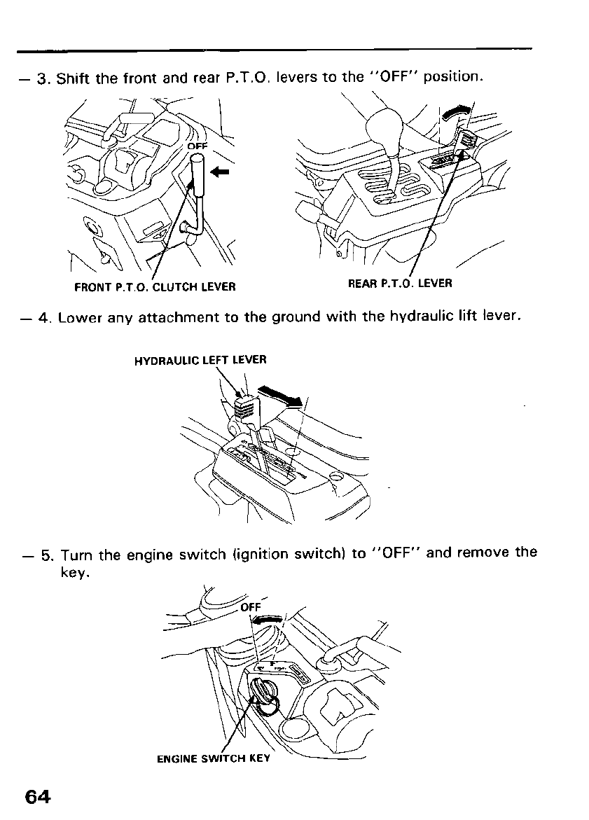
- 3. Shift the front and rear P.T.O. levers to the “OFF” position.
FRONT P.T.O. -CLUTCH LEVER
- 4. Lower any attachment to the ground with the hydraulic lift lever.
HYDRAULIC LEFT LEVER
- 5. Turn the engine switch (ignition switch) to “OFF” and remove the
key.
ENGINE SWITCH K
64
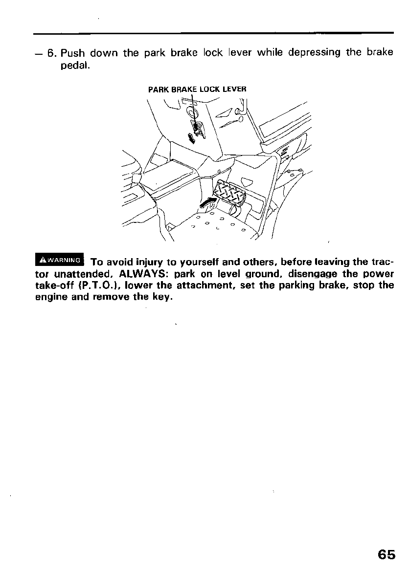
- 6. Push down the park brake lock lever while depressing the brake
pedal.
PARK BRAKE LOCK LEVER
m To avoid injury to yourself and others, before leaving the trac-
tor unattended, ALWAYS: park on level ground, disengage the power
take-off (P.T.O.), lower the attachment, set the parking brake, stop the
engine and remove the key.
65
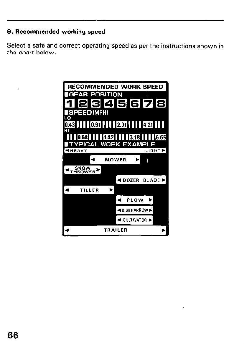
9. Recommended working speed
Select a safe and correct operating speed as per the instructions shown in
the chart below.
RECOMMENDED WORK SPEED
4 DOZER BLADE b[
4 DISKHARROWD
10. High Altitude Operation
At high altitude, the standard carburetor air-fuel mixture will be too rich.
Performance will decrease, and fuel consumption will increase. A very rich
fuel mixture may also foul the spark plugs and cause hard starting.
High altitude performance can be improved by installing a smaller diameter
main fuel jet in the carburetor and readjusting the pilot screw. If you
always operate the engine at altitudeds higher than 6,000 feet above sea
level, have an authorized Honda tractor dealer perform this carburetor
modification.
Even with carburetor modification, engine horsepower will decrease about
3.5% for each 1,000 feet increase in altitude. The effect of altitude on
horsepower will be greater than this if no carburetor modification is made.
IMPORTANT NoT’CE 1 Once a carburetor is jetted for high altitude use,
operation at lower altitudes without rejetting may result in reduced perfor-
mance, overheating, and serious engine damage.
It is especially important to rejet a carburetor when going from a higher
altitude to a lower one. At lower altitudes, the air/fuel mixture may
become excessively lean.
67
7. TRANSPORTING
Transporting
m The engine and exhaust system become hot during operation
and remain hot for a while after stopping. Contact with hot engine com-
ponents or the exhaust system can cause burns and can ignite some
materials.
Avoid touching the engine or exhaust system for at least 15 minutes after
the engine has stopped. Allow the engine to cool before transporting the
tractor.
[ IMPORTANT NOTICE ] T owing the tractor behind another vehicle or using it
to push another vehicle can damage the tractor.
Transport the tractor on a flat, level trailer or in a pickup truck. To avoid
gasoline spillage, keep the tractor level while transporting.
m Gasoline is extremely flammable, and gasoline vapor can ex-
plode, causing injury or death.
Transport the tractor on a flat, level heavy duty trailer.
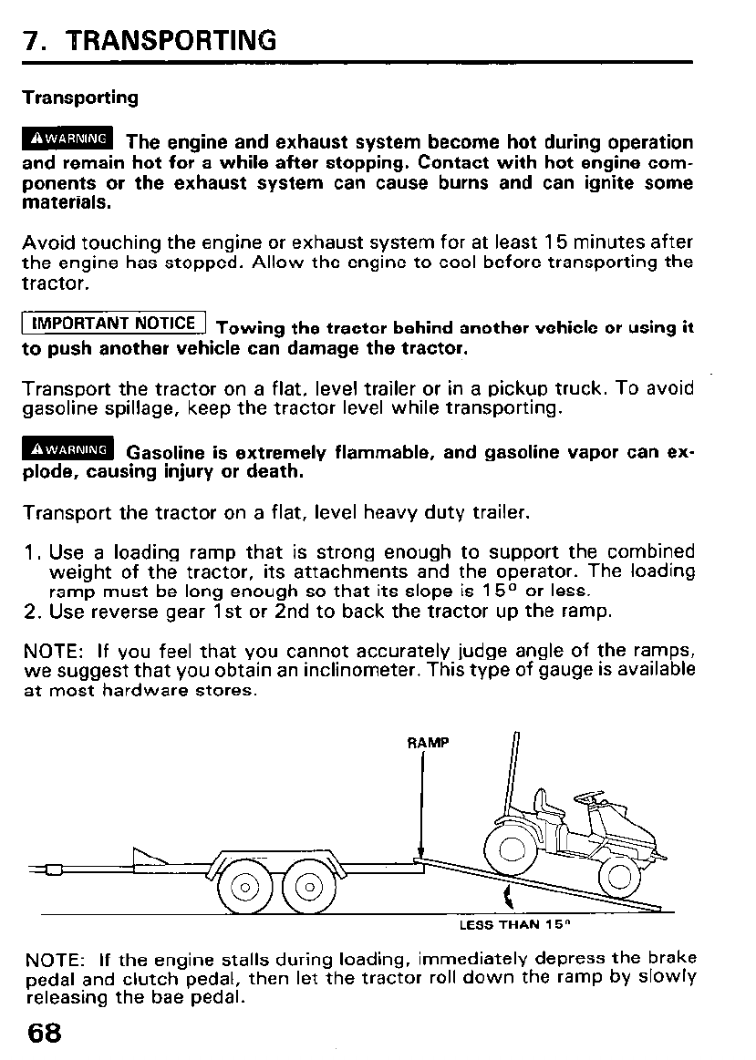
1. Use a loading ramp that is strong enough to support the combined
weight of the tractor, its attachments and the operator. The loading
ramp must be long enough so that its slope is 15O or less.
2. Use reverse gear 1st or 2nd to back the tractor up the ramp.
NOTE: If you feel that you cannot accurately judge angle of the ramps,
we suggest that you obtain an inclinometer. This type of gauge is available
at most hardware stores.
RAMP n
LESS THAN 15”
NOTE: If the engine stalls during loading, immediately depress the brake
pedal and clutch pedal, then let the tractor roll down the ramp by slowly
releasing the bae pedal.
68
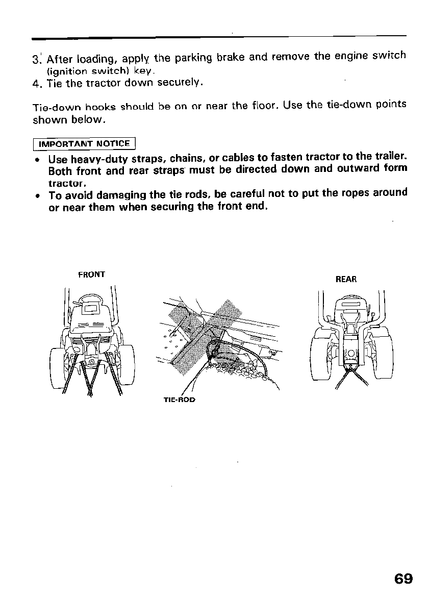
3: After loading, apply the parking brake and remove the engine switch
(ignition switch) key.
4. Tie the tractor down securely.
Tie-down hooks should be on or near the floor. Use the tie-down points
shown below.
1 IMPORTANT NOTICE
. Use heavy-duty straps, chains, or cables to fasten tractor to the trailer.
Both front and rear straps’ must be directed down and outward form
tractor.
l To avoid damaging the tie rods, be careful not to put the ropes around
or near them when securing the front end.
FRONT REAR
T TIE-FiOD
69
8. INSTALLING AN ATTACHMENT
Before installing or using any attachment, carefully read all instructions
and precautions.
m To prevent accidental start-up, remove the engine switch (igni-
tion switch) key, and disconnect the spark plug cap before installing or ad-
justing attachments.
1. Rear 3-point hitch link installation (option)
- 1. Install the hitch box on the tractor with the six bolts and nut nuts.
-2. Attach the check links to the right and left lower links with the check
links pins and secure with the cotter pins.
-3. Install the right and left lower links to the hitch box section with
lower link pins.
-4. Insert the check links to the outside of the lower link pin and secure
with a lock pin.
-5. Attach the lift rod pin to the lift arm.
-6. Install the right side of the lift rod (with the turnbuckle attached) to
the right sides of the lower link and lift arm.
Fit the left side of the lift rod to the left sides of the lower link and lift
arm and secure all attachments with pins.
-7. Install the upper link on the cylinder mounting plate with the four
bolts.
-8. Install and secure the upper link with the link and lock pins.
-9. Check that all parts are installed securely. Tighten the nuts to the
specified torques.
70
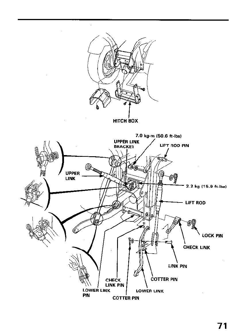
HITCH iOX
7.0 kg-m (50.6 ft-lbs)
2.2 kg (15.9 ft-lbsj
uFT ROD
’ LOCK PIN
:CK LINK
71
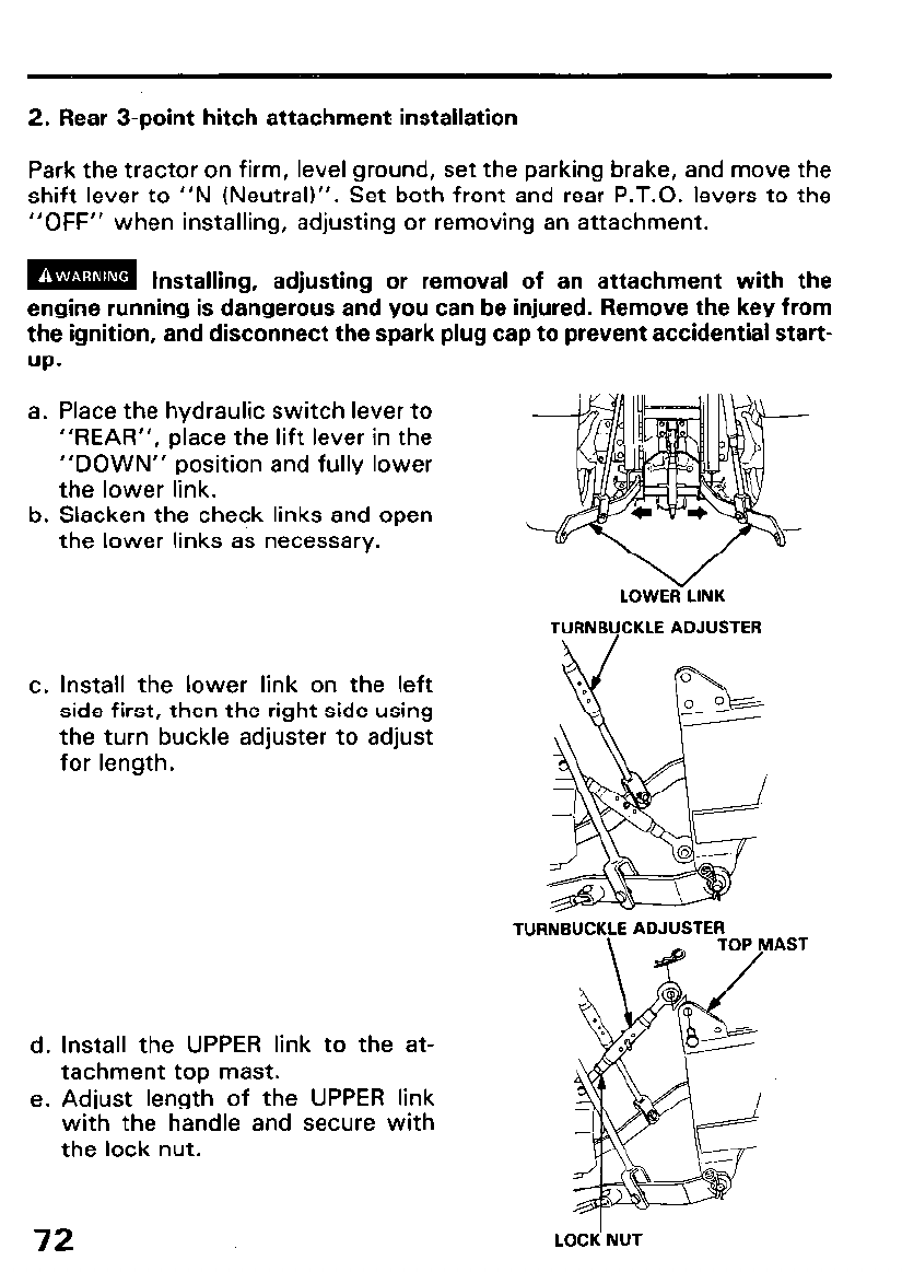
2. Rear 3-point hitch attachment installation
Park the tractor on firm, level ground, set the parking brake, and move the
shift lever to “N (Neutral)“. Set both front and rear P.T.O. levers to the
“OFF” when installing, adjusting or removing an attachment.
m Installing, adjusting or removal of an attachment with the
engine running is dangerous and you can be injured. Remove the key from
the ignition, and disconnect the spark plug cap to prevent accidential start-
UP-
a. Place the hydraulic switch lever to
“REAR”, place the lift lever in the
“DOWN” position and fully lower
the lower link.
b. Slacken the check links and open
the lower links as necessary.
c. Install the lower link on the left
side first, then the right side using
the turn buckle adjuster to adjust
for length.
d. Install the UPPER link to the at-
tachment top mast.
e. Adjust length of the UPPER link
with the handle and secure with
the lock nut.
LOWE<LINK
TURNBUCKLE ADJUSTER
TURNBUCKLE ADJUSTER AS1
72 LO& NUT
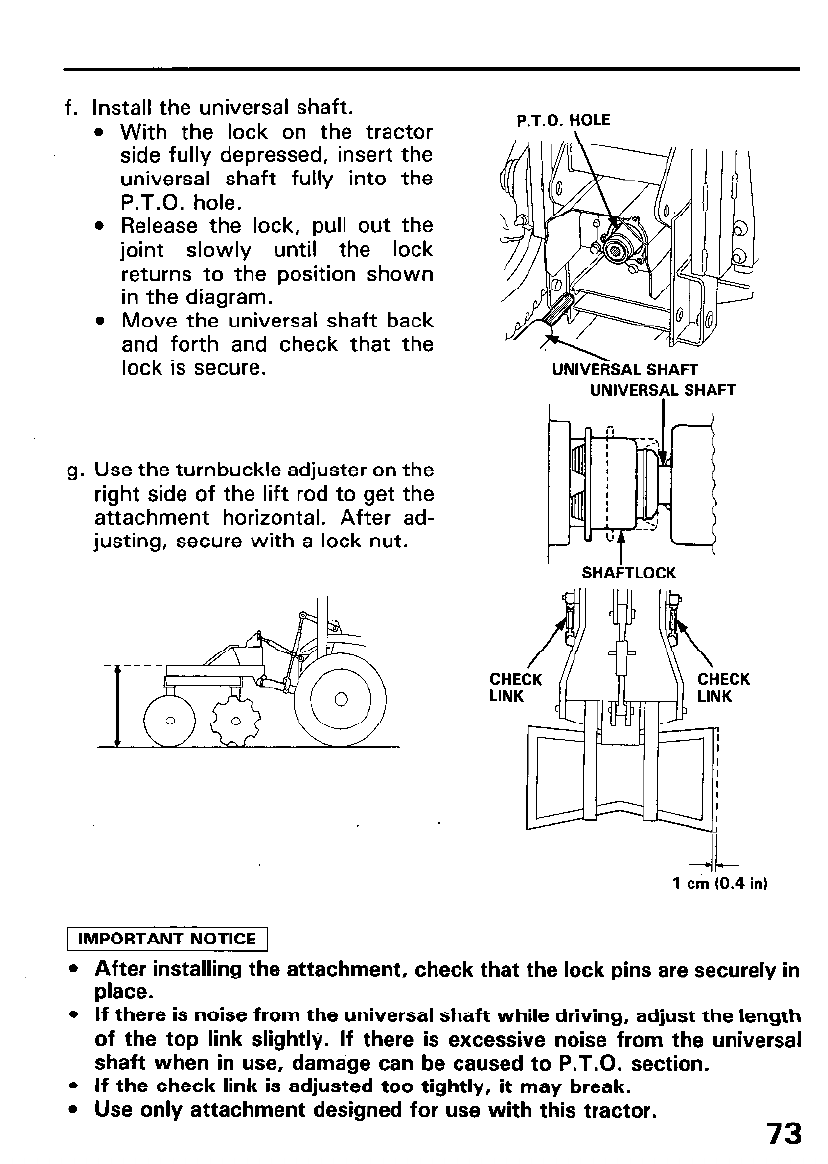
cl.
Install the universal shaft.
With the lock on the tractor
side fully depressed, insert the
universal shaft fully into the
P.T.O. hole.
Release the lock, pull out the
joint slowly until the lock
returns to the position shown
in the diagram.
Move the universal shaft back
and forth and check that the
lock is secure.
h Id
Use the turnbuckle adjuster on the
right side of the lift rod to get the
attachment horizontal. After ad-
justing, secure with a lock nut.
UNlVEFiSAL SHAFT
UNIVERS(IL SHAFT
CH ECK
LIN K
-II-
1 cm (0.4 in)
1 IMPORTANT NOTICE 1
l After installing the attachment, check that the lock pins are securely in
place.
l If there is noise from the universal shaft while driving, adjust the length
of the top link slightly. If there is excessive noise from the universal
shaft when in use, damage can be caused to P.T.O. section.
l If the check link is adjusted too tightly, it may break.
l Use only attachment designed for use with this tractor. 73
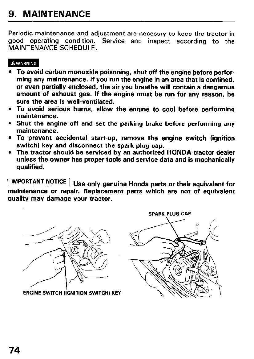
9. MAINTENANCE
Periodic maintenance and adjustment are necessry to keep the tractor in
good operating condition. Service and inspect according to the
MAINTENANCE SCHEDULE.
To avoid carbon monoxide poisoning, shut off the engine before perfor-
ming any maintenance. If you run the engine in an area that is confined,
or even partially enclosed, the air you breathe will contain a dangerous
amount of exhaust gas. If the engine must be run for any reason, be
sure the area is well-ventilated.
To avoid serious burns, allow the engine to cool before performing
maintenance.
Shut the engine off and set the parking brake before performing any
maintenance.
To prevent accidental start-up, remove the engine switch (ignition
switch) key and disconnect the spark plug cap.
The tractor should be serviced by an authorized HONDA tractor dealer
unless the owner has proper tools and service data and is mechanically
qualified.
1 IMPORTANT NOTICE 1 u se only genuine Honda parts or their equivalent for
maintenance or repair. Replacement parts which are not of equivalent
quality may damage your tractor.
SPARK PLUG CAP
ENGINE SWITCH (IGNITION SWITCH) KEY
74
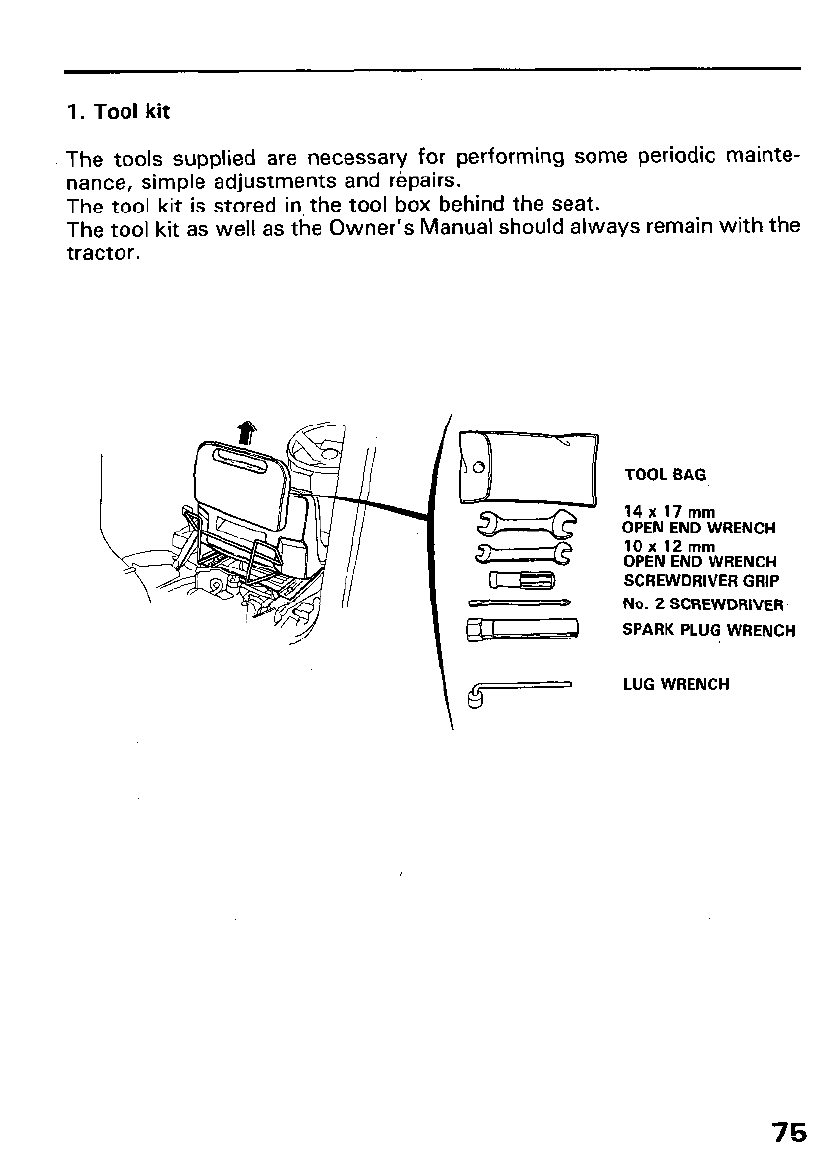
1. Tool kit
The tools supplied are necessary for performing some periodic mainte-
nance, simple adjustments and repairs.
The tool kit is stored in the tool box behind the seat.
The tool kit as well as the Owner’s Manual should always remain with the
tractor.
iL=J
Q
TOOL BAG
14x 17mm
OPEN END WRENCH
10 x 12 mm
OPEN END WRENCH
SCREWDRIVER GRIP
No. 2 SCREWDRIVER
SPARK PLUG WRENCH
LUG WRENCH
\
75
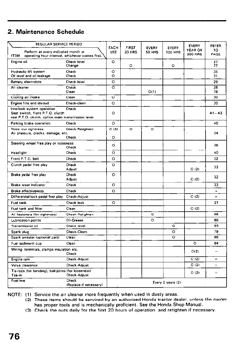
2. Maintenance Schedule
NOTE: (1) Service the air cleaner more frequently when used in dusty areas.
(2) These items should be serviced by an authorized Honda tractor dealer, unless the owner
has proper tools and is mechanically proficient. See the Honda Shop Manual.
(3) Check the nuts daily for the first 20 hours of operation, and retighten if necessary.
76
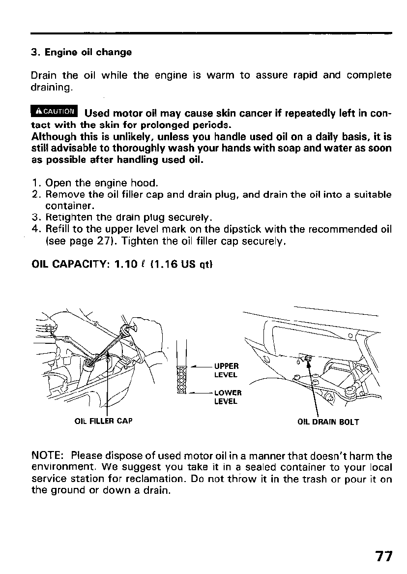
3. Engine oil change
Drain the oil while the engine is warm to assure rapid and complete
draining.
m Used motor oil mav cause skin cancer if repeatedlv left in con-
tact with the skin for prolonged periods.
Although this is unlikely, unless you handle used oil on a daily basis, it is
still advisable to thoroughly wash your hands with soap and water as soon
as possible after handling used oil.
1. Open the engine hood.
2. Remove the oil filler cap and drain plug, and drain the oil into a suitable
container.
3. Retighten the drain plug securely.
4. Refill to the upper level mark on the dipstick with the recommended oil
(see page 27). Tighten the oil filler cap securely.
OIL CAPACITY: 1.10 P (1.16 US qt)
-LOWER
LEVEL
OIL FILLER CAP OIL iRAIN BOLT
NOTE: Please dispose of used motor oil in a manner that doesn’t harm the
environment. We suggest you take it in a sealed container to your local
service station for reclamation. Do not throw it in the trash or pour it on
the ground or down a drain.
77
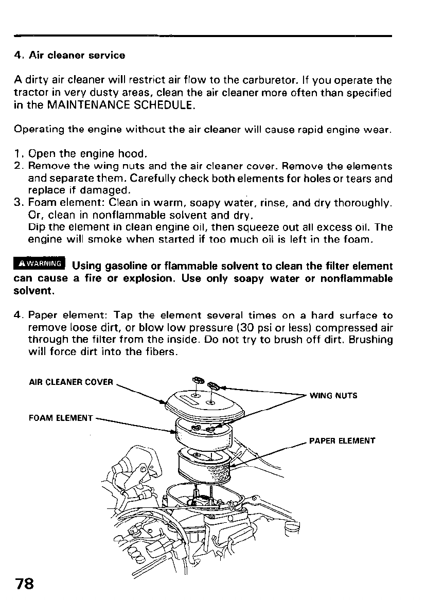
4. Air cleaner service
A dirty air cleaner will restrict air flow to the carburetor. If you operate the
tractor in very dusty areas, clean the air cleaner more often than specified
in the MAINTENANCE SCHEDULE.
Operating the engine without the air cleaner will cause rapid engine wear.
1. Open the engine hood.
2. Remove the wing nuts and the air cleaner cover. Remove the elements
and separate them. Carefully check both elements for holes or tears and
replace if damaged.
3. Foam element: Clean in warm, soapy water, rinse, and dry thoroughly.
Or, clean in nonflammable solvent and dry.
Dip the element in clean engine oil, then squeeze out all excess oil. The
engine will smoke when started if too much oil is left in the foam.
m Using gasoline or flammable solvent to clean the filter element
- -
can cause a fire or explosion. Use only soapy water or nonflammable
solvent.
4. Paper element: Tap the element several times on a hard surface to
remove loose dirt, or blow low pressure (30 psi or less) compressed air
through the filter from the inside. Do not try to brush off dirt. Brushing
will force dirt into the fibers.
AIR CLEANER COVER
FOAM ELEMENT
78
WING NUTS
PAPER ELEMENT
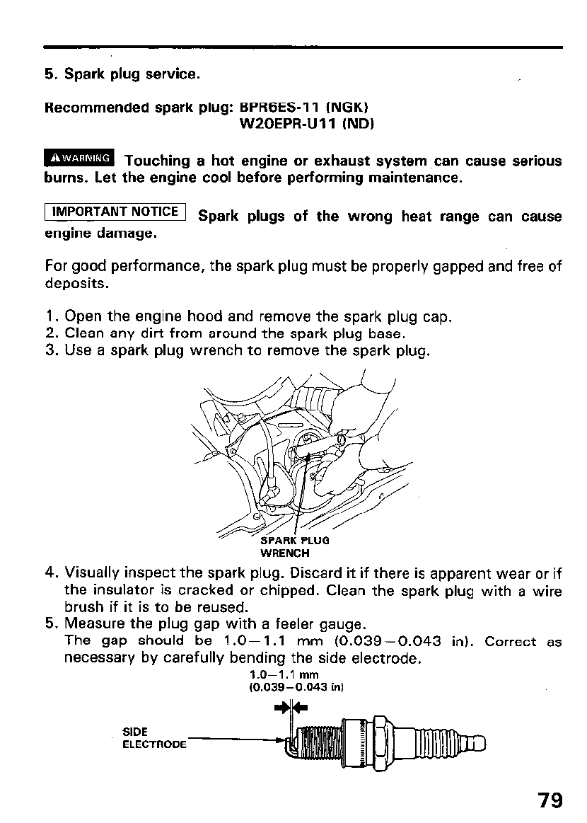
5. Spark plug service.
Recommended spark plug: BPRGES-11 (NGK)
W20EPR-U 11 (ND)
m Touching a hot engine or exhaust system can cause serious
burns. Let the engine cool before performing maintenance.
1 IMPORTANT NoT’CE 1 Spark plugs of the wrong heat range can cause
engine damage.
For good performance, the spark plug must be properly gapped and free of
deposits.
1. Open the engine hood and remove the spark plug cap.
2. Clean any dirt from around the spark plug base.
3. Use a spark plug wrench to remove the spark plug.
WRENCH
4. Visually inspect the spark plug. Discard it if there is apparent wear or if
the insulator is cracked or chipped. Clean the spark plug with a wire
brush if it is to be reused.
5. Measure the plug gap with a feeler gauge.
The gap should be 1.0-l .l mm (0.039-0.043 in). Correct as
necessary by carefully bending the side electrode.
1.0-1.1 mm
(0.039-0.043 in1
SIDE
ELECTRODE
79
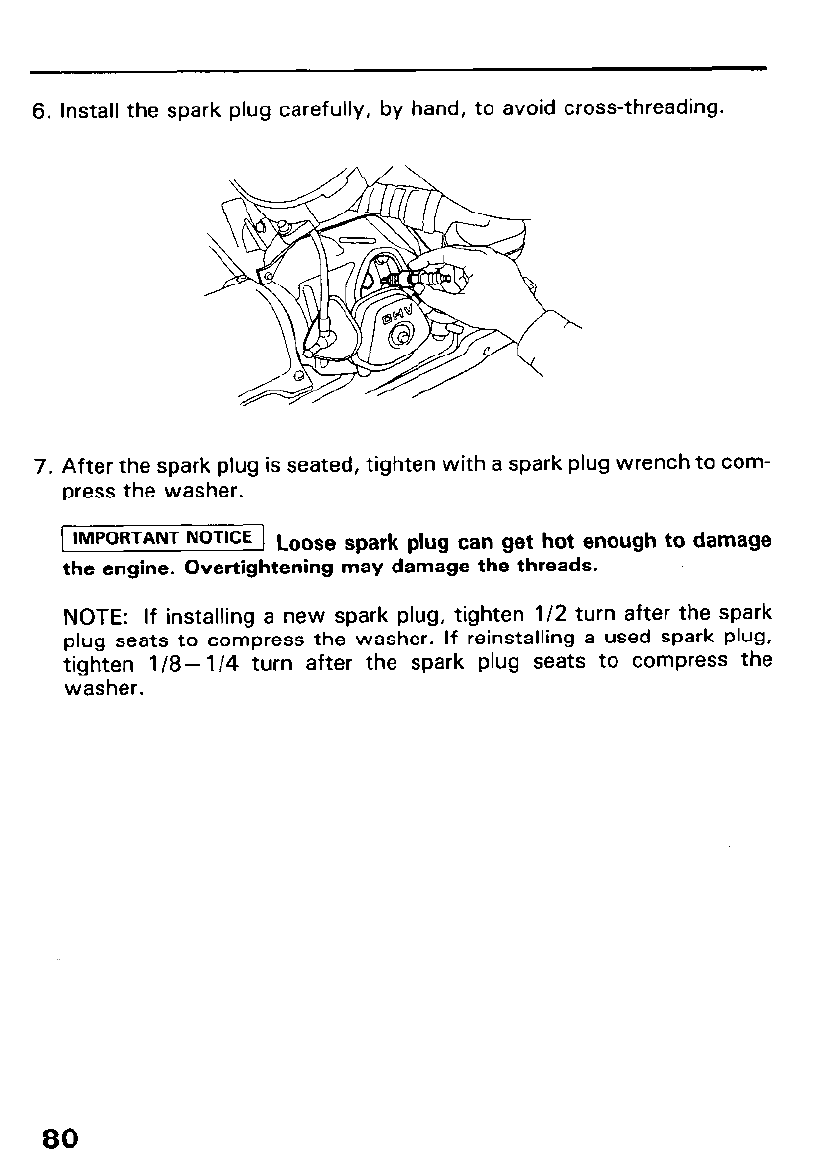
6. Install the spark plug carefully, by hand, to avoid cross-threading.
7. After the spark plug is seated, tighten with a spark plug wrench to com-
press the washer.
1 IMPORTANT NoTlCE 1 Loose spark plug can get hot enough to damage
the engine. Overtightening may damage the threads.
NOTE: If installing a new spark plug, tighten l/2 turn after the spark
plug seats to compress the washer. If reinstalling a used spark plug,
tighten l/8- l/4 turn after the spark plug seats to compress the
washer.
80
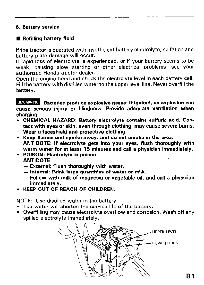
6. Battery service
l Refilling battery fluid
If the tractor is operated with insufficient battery electrolyte, sulfation and
battery plate damage will occur.
If rapid loss of electrolyte is experienced, or if your battery seems to be
weak, causing slow starting or other electrical problems, see your
authorized Honda tractor dealer.
Open the engine hood and check the electrolyte level in each battery cell.
Fill the battery with distilled water to the upper level line. Never overfill the
battery.
m Batteries produce explosive gases: If ignited, an explosion can
cause serious injury or blindness. Provide adequate ventilation when
charging.
l CHEMICAL HAZARD: Battery electrolyte contains sulfuric acid. Con-
tact with eyes or skin, even through clothing, may cause severe burns.
Wear a faceshield and protective clothing.
l Keep flames and sparks away, and do not smoke in the area.
ANTIDOTE: If electrolyte gets into your eyes, flush thoroughly with
warm water for at least 15 minutes and call a physician immediately.
l POISON: Electrolyte is poison.
ANTIDOTE
- External: Flush thoroughly with water.
- Internal: Drink large quantities of water or milk.
Follow with milk of magnesia or vegetable oil, and call a physician
immediately.
l KEEP OUT OF REACH OF CHILDREN.
NOTE: Use distilled water in the battery.
l Tap water will shorten the service life of the battery.
l Overfilling may cause electrolyte overflow and corrosion. Wash off any
spilled electrolyte immediately.
UPPER LEVEL
LOWER LEVEL
81
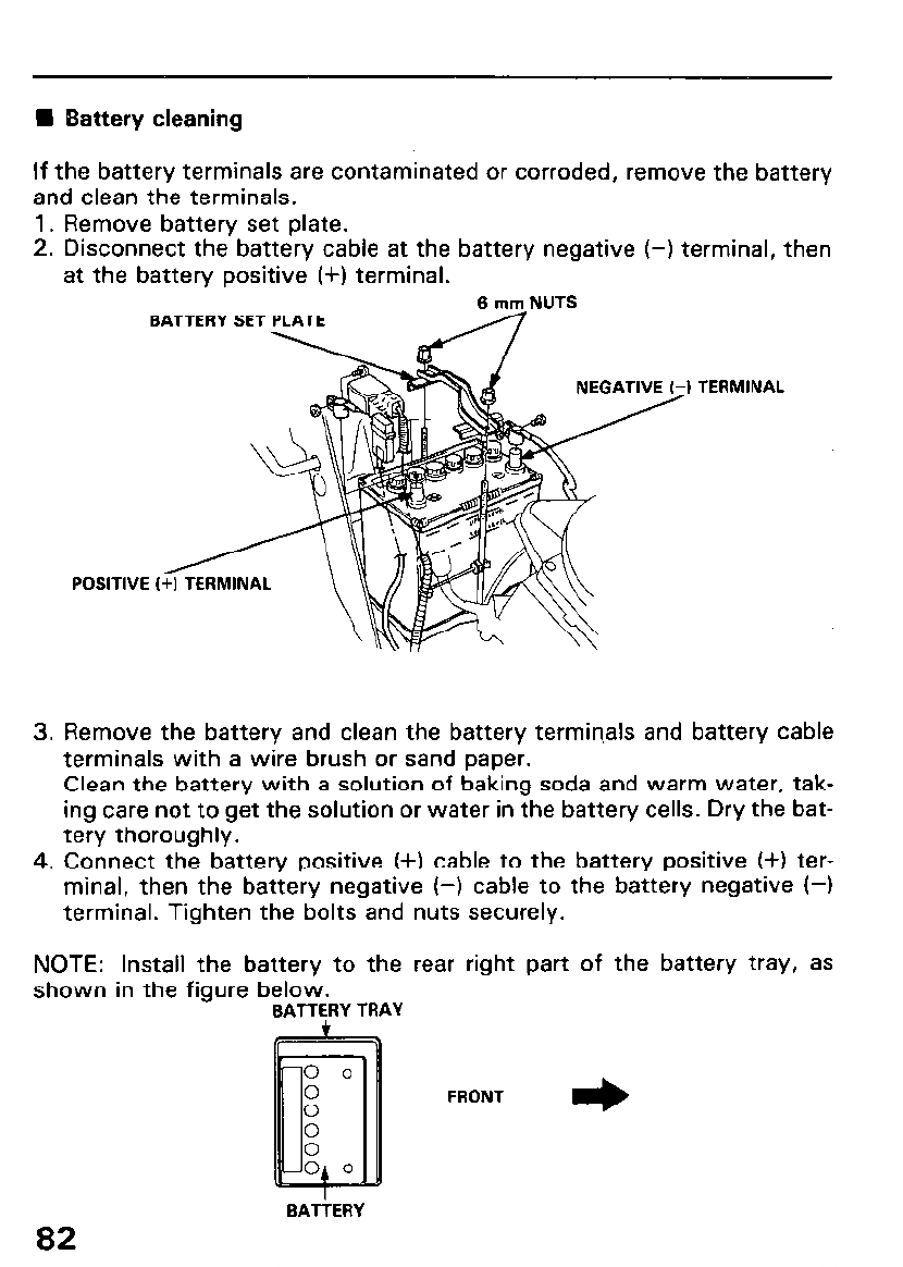
n Battery cleaning
If the battery terminals are contaminated or corroded, remove the battery
and clean the terminals.
1. Remove battery set plate.
2. Disconnect the battery cable at the battery negative (-1 terminal, then
at the battery positive (+) terminal.
6 mm NUTS
BATTERY SET
) TERMINAL
3. Remove the battery and clean the battery termin,als and battery cable
terminals with a wire brush or sand paper.
Clean the battery with a solution of baking soda and warm water, tak-
ing care not to get the solution or water in the battery cells. Dry the bat-
tery thoroughly.
4. Connect the battery positive (+I cable to the battery positive (+I ter-
minal, then the battery negative f-1 cable to the battery negative (-1
terminal. Tighten the bolts and nuts securely.
NOTE: Install the battery to the rear right part of the battery tray, as
shown in the figure below.
BAlTERY TRAY
FRONT +
82
BATiERY
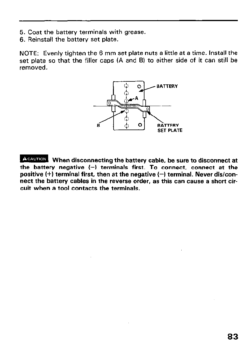
5. Coat the battery terminals with grease.
6. Reinstall the battery set plate.
NOTE: Evenly tighten the 6 mm set plate nuts a little at a time. Install the
set plate so that the filler caps (A and B) to either side of it can still be
removed.
SET PLATE
m When disconnecting the battery cable, be sure to disconnect at
the battery negative (-1 terminals first. To connect, connect at the
positive (+I terminal first, then at the negative (-1 terminal. Never dis/con-
nect the battery cables in the reverse order, as this can cause a short cir-
cuit when a tool contacts the terminals.
83
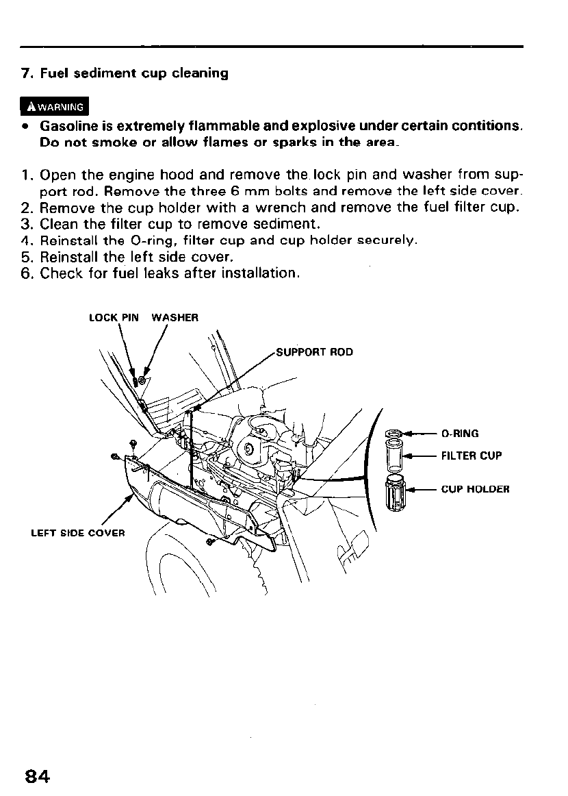
7. Fuel sediment cup cleaning
m
l Gasoline is extremely flammable and explosive under certain contitions.
Do not smoke or allow flames or sparks in the area.
1. Open the engine hood and remove the lock pin and washer from sup-
port rod. Remove the three 6 mm bolts and remove the left side cover.
2. Remove the cup holder with a wrench and remove the fuel filter cup.
3. Clean the filter cup to remove sediment.
4. Reinstall the O-ring, filter cup and cup holder securely.
5. Reinstall the left side cover.
6. Check for fuel leaks after installation.
LOCK PIN WASHER
LEFT SIDE
SUPPORT ROD
O-RING
FILTER CUP
CUP HOLDER
84
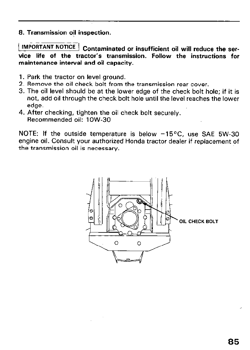
8. Transmission oil inspection.
1 IMPORTANT NOTICE 1 c ontaminated or insufficient oil will reduce the ser-
vice life of the tractor’s transmission. Follow the instructions for
maintenance interval and oil capacity.
1. Park the tractor on level ground.
2. Remove the oil check bolt from the transmission rear cover.
3. The oil level should be at the lower edge of the check bolt hole; if it is
not, add oil through the check bolt hole until the level reaches the lower
edge.
4. After checking, tighten the oil check bolt securely.
Recommended oil: 1 OW-30
NOTE: If the outside temperature is below -15OC, use SAE 5W-30
engine oil. Consult your authorized Honda tractor dealer if replacement of
the transmission oil is necessary.
OIL CHECK BOLT
85
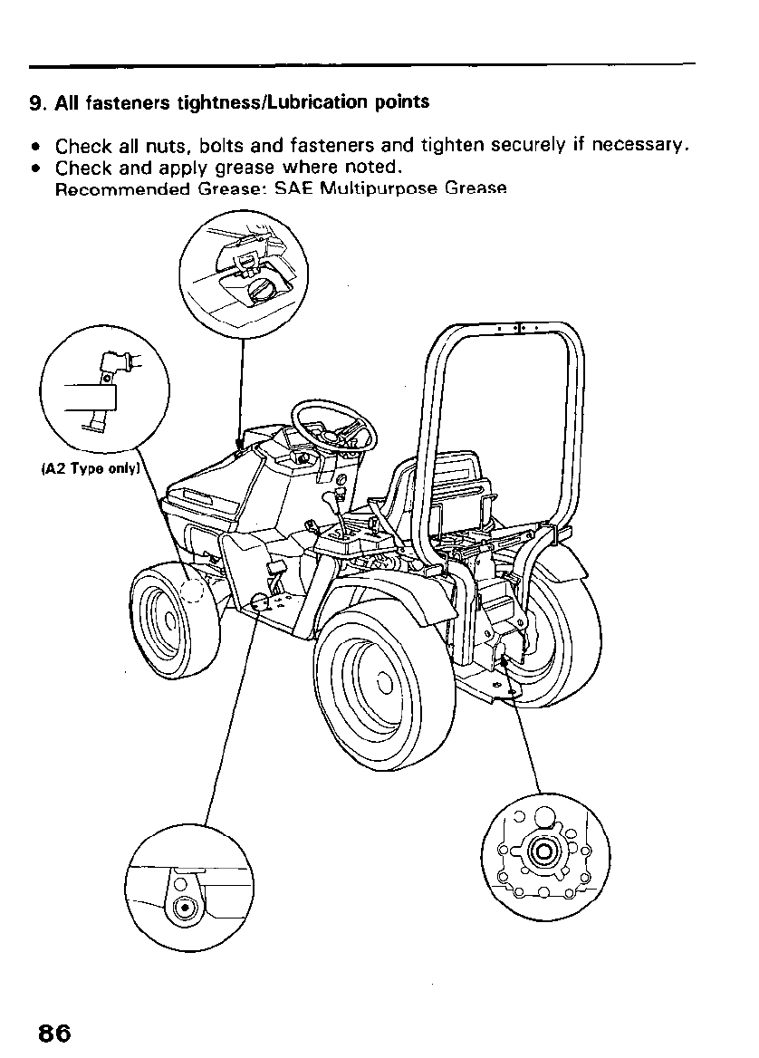
9. All fasteners tightness/Lubrication points
l Check all nuts, bolts and fasteners and tighten securely if necessary.
l Check and apply grease where noted.
Recommended Grease: SAE Multipurpose Grease
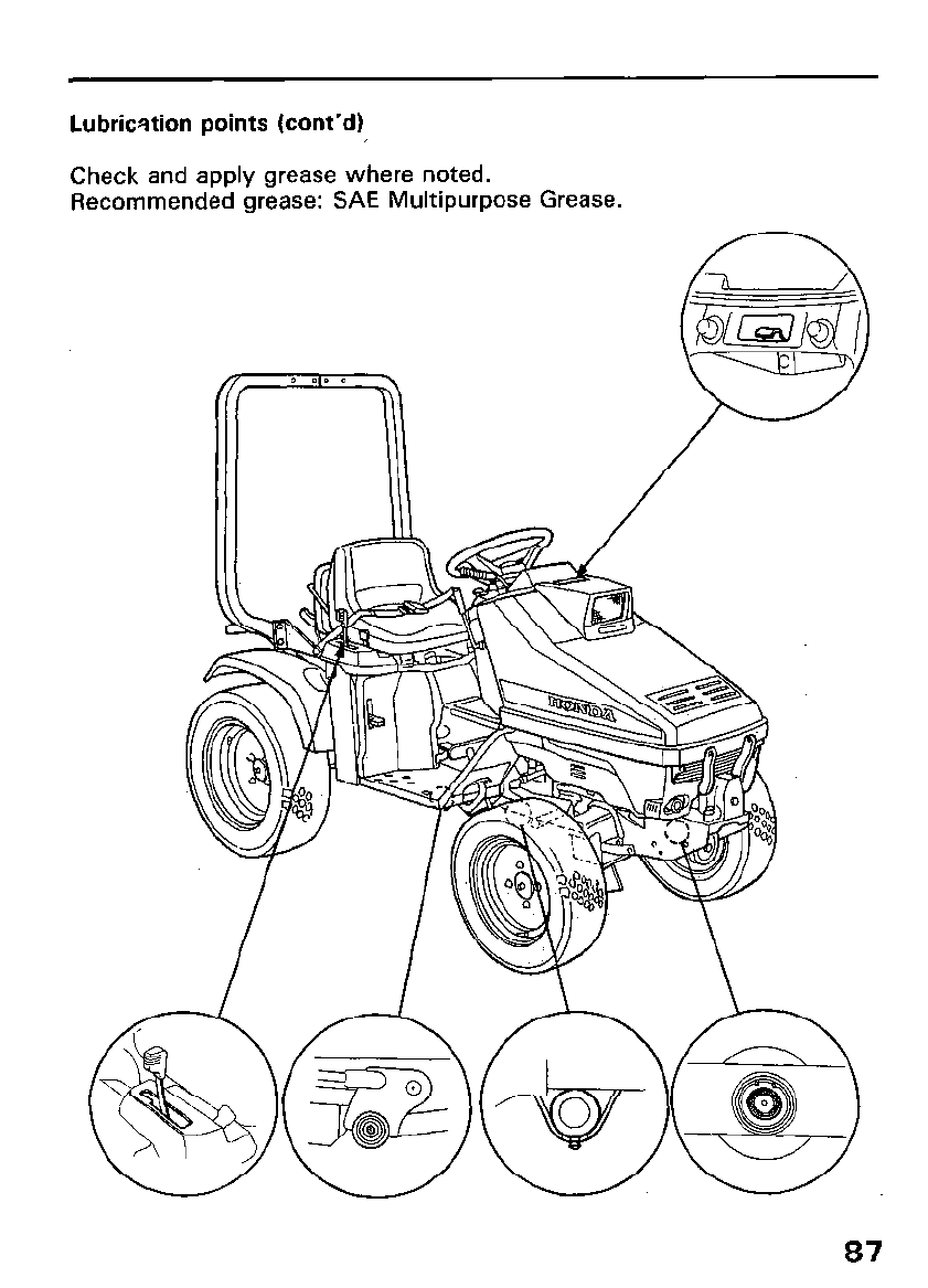
Lubrication points (cont’d)
Check and apply grease where noted.
Recommended grease: SAE Multipurpose Grease.
87
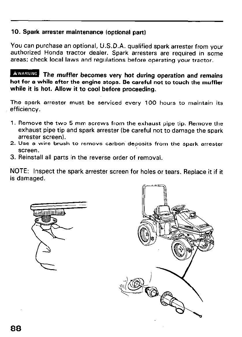
10. Spark arrester maintenance (optional part)
You can purchase an optional, U.S.D.A. qualified spark arrester from your
authorized Honda tractor dealer. Spark arresters are required in some
areas; check local laws and regulations before operating your tractor.
m The muffler becomes very hot during operation and remains
hot for a while after the engine stops. Be careful not to touch the muffler
while it is hot. Allow it to cool before proceeding.
The spark arrester must be serviced every 100 hours to maintain its
efficiency.
1. Remove the two 5 mm screws from the exhaust pipe tip. Remove the
exhaust pipe tip and spark arrester (be careful not to damage the spark
arrester screen).
2. Use a wire brush to remove carbon deposits from the spark arrester
screen.
3. Reinstall all parts in the reverse order of removal.
88
NOTE: Inspect the spark arrester screen for holes or tears. Replace it if it
is damaged.
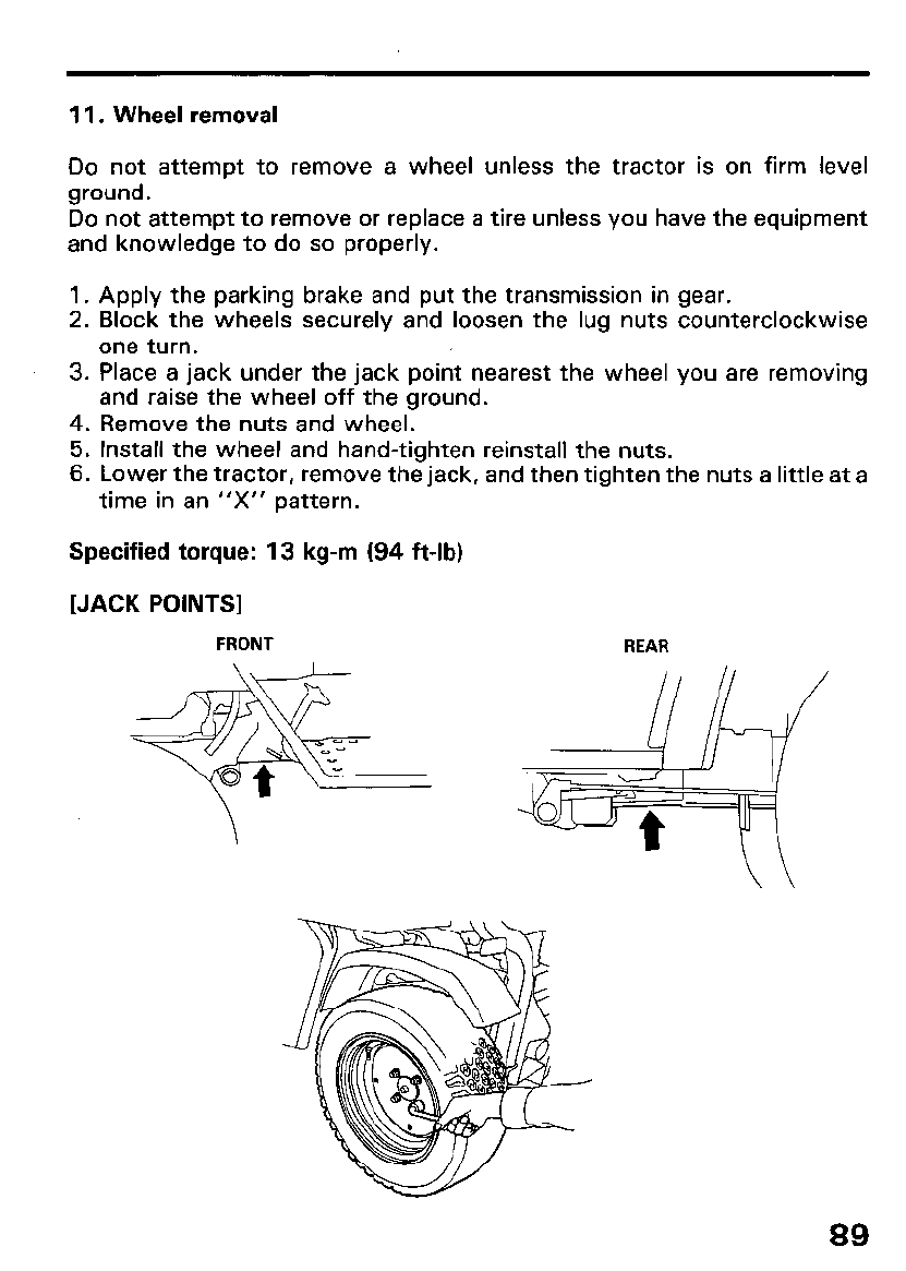
11. Wheel removal
Do not attempt to remove a wheel unless the tractor is on firm level
ground.
Do not attempt to remove or replace a tire unless you have the equipment
and knowledge to do so properly.
1. Apply the parking brake and put the transmission in gear.
2. Block the wheels securely and loosen the lug nuts counterclockwise
one turn.
3. Place a jack under the jack point nearest the wheel you are removing
and raise the wheel off the ground.
4. Remove the nuts and wheel.
5. Install the wheel and hand-tighten reinstall the nuts.
6. Lower the tractor, remove the jack, and then tighten the nuts a little at a
time in an “X” pattern.
Specified torque: 13 kg-m (94 ft-lb)
(JACK POINTS]
FRONT REAR
\
89
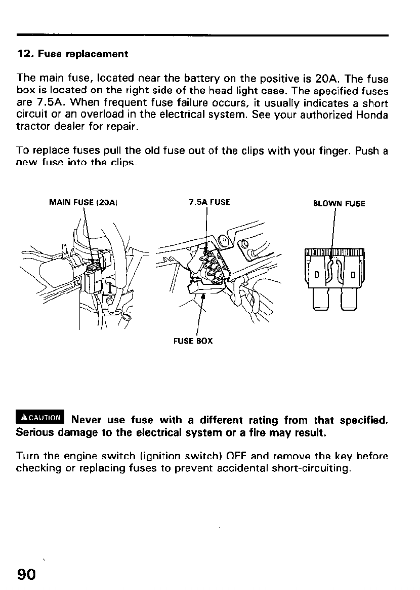
12. Fuse replacement
The main fuse, located near the battery on the positive is 20A. The fuse
box is located on the right side of the head light case. The specified fuses
are 7.5A. When frequent fuse failure occurs, it usually indicates a short
circuit or an overload in the electrical system. See your authorized Honda
tractor dealer for repair.
To replace fuses pull the old fuse out of the clips with your finger. Push a
new fuse into the clips.
MAIN FUSE (20A) 7.5A FUSE BLOWN FUSE
I
FUSE ‘BOX
m Never use fuse with a different rating from that specified.
Serious damage to the electrical system or a fire may result.
Turn the engine switch (ignition switch) OFF and remove the key before
checking or replacing fuses to prevent accidental short-circuiting.
90
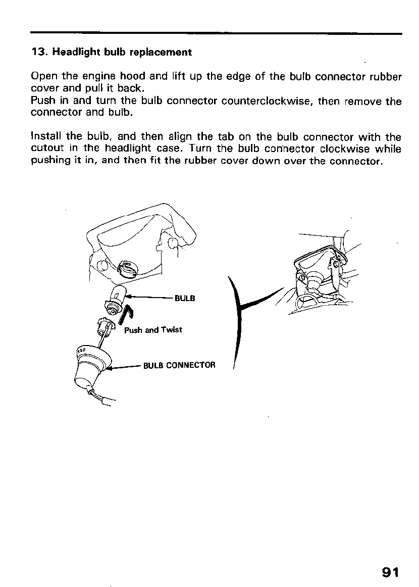
13. Headlight bulb replacement
Open the engine hood and lift up the edge of the bulb connector rubber
cover and pull it back.
Push in and turn the bulb connector counterclockwise, then remove the
connector and bulb.
Install the bulb, and then align the tab on the bulb connector with the
cutout in the headlight case. Turn the bulb connector clockwise while
pushing it in, and then fit the rubber cover down over the connector.
n BULB
Push and Twist
BULB CONNECTOR
91
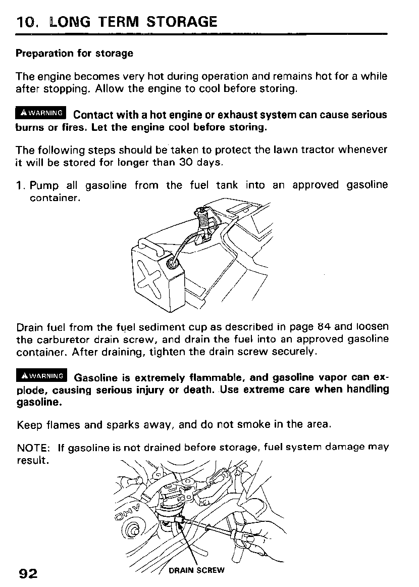
10. LONG TERfVl STORAGE
Preparation for storage
The engine becomes very hot during operation and remains hot for a while
after stopping. Allow the engine to cool before storing.
m Contact with a hot engine or exhaust system can cause serious
burns or fires. Let the engine cool before storing.
The following steps should be taken to protect the lawn tractor whenever
it will be stored for longer than 30 days.
1. Pump all gasoline from the fuel tank into an approved gasoline
container.
Drain fuel from the fuel sediment cup as described in page 84 and loosen
the carburetor drain screw, and drain the fuel into an approved gasoline
container. After draining, tighten the drain screw securely.
m Gasoline is extremely flammable, and gasoline vapor can ex-
plode, causing serious injury or death. Use extreme care when handling
gasoline.
Keep flames and sparks away, and do not smoke in the area.
NOTE: If gasoline is not drained before storage, fuel system damage may
result.
92
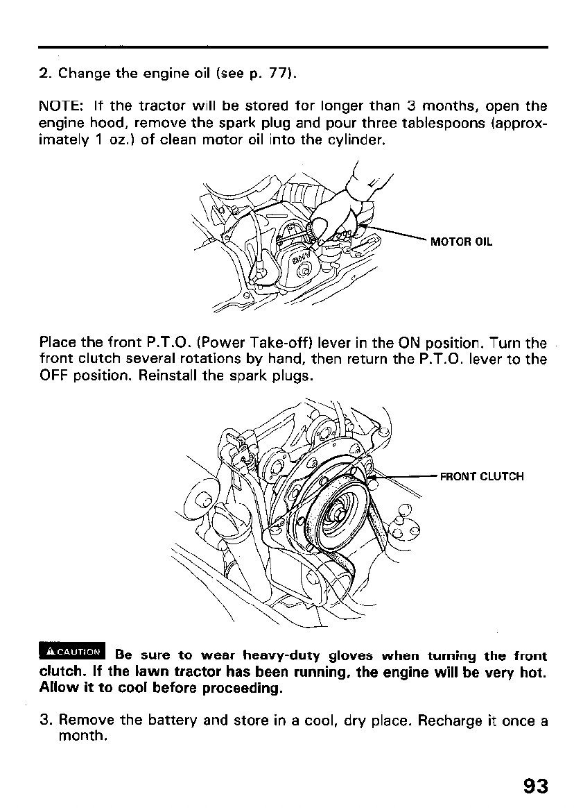
2. Change the engine oil (see p. 77).
NOTE: If the tractor will be stored for longer than 3 months, open the
engine hood, remove the spark plug and pour three tablespoons (approx-
imately 1 oz.) of clean motor oil into the cylinder.
MOTOR OIL
Place the front P.T.O. (Power Take-off) lever in the ON position. Turn the
front clutch several rotations by hand, then return the P.T.O. lever to the
OFF position. Reinstall the spark plugs.
FRONT CLUTCH
m Be sure to wear heavy-duty gloves when turning the front
clutch. If the lawn tractor has been running, the engine will be very hot.
Allow it to cool before proceeding.
3. Remove the battery and store in a cool, dry place. Recharge it once a
month.
93
4. Store the tractor on a level surface in a dry, dust-free area with the
parking brake lever set.
5. Cover the tractor to keep out dust.
6. Check tire air pressure regularly during storage and inflate if necessary.
Removal from storage
1. Check the battery electrolyte level (see p. 29). Fully recharge the bat-
tery, and install it in the tractor.
2. Remove the spark plug and check that it is clean and properly gapped
(see p. 79). Turn the engine a few revolutions with the starter motor
before reinstalling the spark,plug.
3. Thread the spark plug in as far as possible by hand, then tighten it l/8
to l/4 turn further with the plug wrench.
4. Check the engine oil level (see p. 27).
5. Fill the fuel tank, and start the engine by following the starting instruc-
tions (see p. 45).
NOTE: If the cylinder was coated with oil, the engine will initially smoke
at start up; this is normal.
94
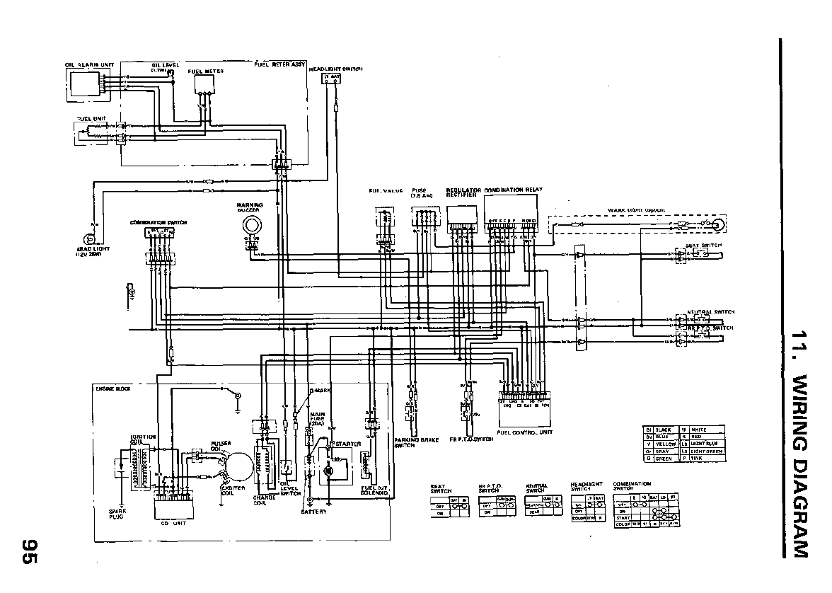
11. WIRING DIAGRAM
I””
r-2. iii
95
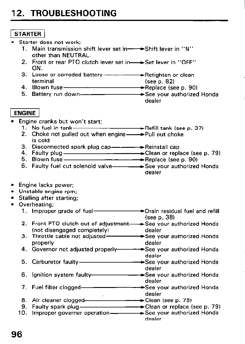
12. TROUBLESHOOTING
(1
l Starter does not work;
1. Main transmission shift lever set in- Shift lever in “N”
other than NEUTRAL.
2. Front or rear PTO clutch lever set i -Set lever in “OFF”
ON.
3. Loose or corroded battery
terminal
4. Blown fuse
5. Battery run down
DRetighten or clean
(see p. 82)
WReplace (see p. 90)
WSee your authorized Honda
dealer
l Engine cranks but won’t start;
1. No fuel in tank *Refill tank (see p. 37)
2. Choke not pulled out when engine- Pull out choke
is cold
3. Disconnected spark plug cap- Reinstall cap
4. Faulty plug WClean or replace (see p. 79)
5. Blown fuse ,Replace (see p. 90)
6. Faulty fuel cut solenoid valve- See your authorized Honda
dealer
l Engine lacks power;
l Unstable engine rpm;
l Stalling after starting;
l Overheating;
1.
2.
3.
4.
5.
6.
7.
8.
9.
10.
96
Improper grade of fuel &Drain residual fuel and refill
(see p. 38)
Front PTO clutch out of adjustment- See your authorized Honda
(not disengaged completely) dealer
Throttle cable not adjusted -See your authorized Honda
properly dealer
Governor not adjusted proper1 y-bSee your authorized Honda
dealer
Carburetor faulty &See your authorized Honda
dealer
Ignition system faultypmsee your authorized Honda
dealer
Fuel filter clogged &See your authorized Honda
dealer
Air cleaner cloggeMClean (see p. 78)
Faulty spark plug *Clean or replace (see p. 79)
Improper governer operation- See your authorized Honda
dealer
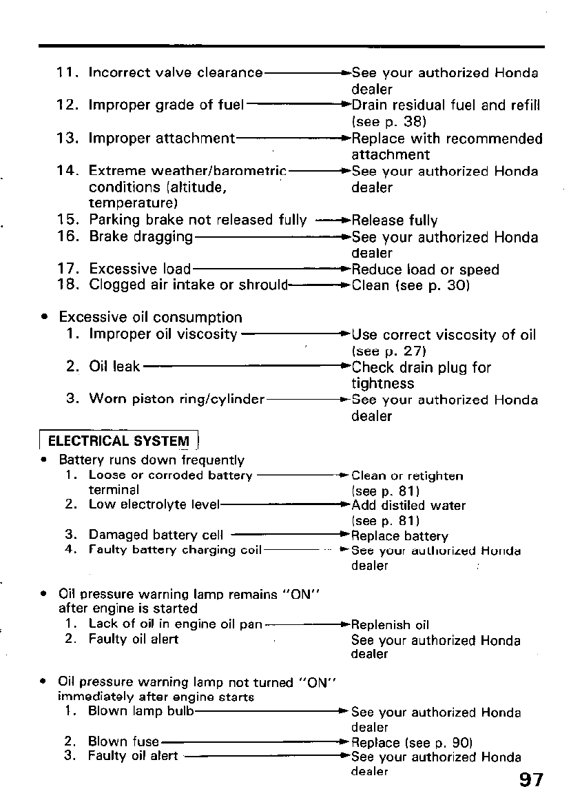
11. Incorrect valve clearance -See your authorized Honda
dealer
12. Improper grade of fuel *Drain residual fuel and refill
(see p. 38)
13. Improper attachment *Replace with recommended
attachment
14. Extreme weather/barometric- See your authorized Honda
conditions (altitude, dealer
temperature)
15. Parking brake not released fully -Release fully
16. Brake dragging DSee your authorized Honda
dealer
17. Excessive load WReduce load or speed
18. Clogged air intake or shrould- Clean (see p. 30)
l Excessive oil consumption
1. Improper oil viscosity muse correct viscosity of oil
(see p. 27)
2. Oil leak *Check drain plug for
tightness
3. Worn piston ring/cylinder- See your authorized Honda
dealer
1 ELECTRICAL SYSTEM ]
l Battery runs down frequently
1. Loose or corroded battery ,Clean or retighten
terminal (see p. 81)
2. Low electrolyte level WAdd distiled water
(see p. 81)
3. Damaged battery cell ‘Replace battery
4. Faulty battery charging coil- See your authorized Honda
dealer
l Oil pressure warning lamp remains “ON”
after engine is started
1. Lack of oil in engine oil pan-Replenish oil
2. Faulty oil alert See your authorized Honda
dealer
l Oil pressure warning lamp not turned “ON”
immediately after engine starts
1. Blown lamp bulb *See your authorized Honda
dealer
2. Blown fuse *Replace (see p. 90)
3. Faulty oil alert YSee your authorized Honda
dealer
97
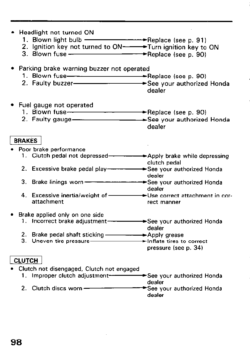
l Headlight not turned ON
1. Blown light bulb Weplace (see p. 91)
2. Ignition key not turned to ON- Turn ignition key to ON
3. Blown fuse Weplace (see p. 90)
l Parking brake warning buzzer not operated
1. Blown fuse ,Replace (see p. 90)
2. Faulty buzzer @See your authorized Honda
dealer
l Fuel gauge not operated
1. Blown fuse
2. Faulty gauge
WReplace (see p. 90)
&ee your authorized Honda
dealer
[ BRAKES ]
l Poor brake performance
1. Clutch pedal not depressed *Apply brake while depressing
clutch pedal
2. Excessive brake pedal play
3. Brake linings worn
WSee your authorized Honda
dealer
Gee your authorized Honda
dealer
4. Excessive inertia/weight of -Use correct attachment in cor-
attachment rect manner
l Brake applied only on one side
1. Incorrect brake adjustment- See your authorized Honda
dealer
2. Brake pedal shaft sticking
3. Uneven tire pressure mApply grease
blnflate tires to correct
pressure (see p. 34)
1 CLUTCH ]
l Clutch not disengaged, Clutch not engaged
1. Improper clutch adjustment- See your authorized Honda
dealer
2. Clutch discs worn *See your authorized Honda
dealer
98
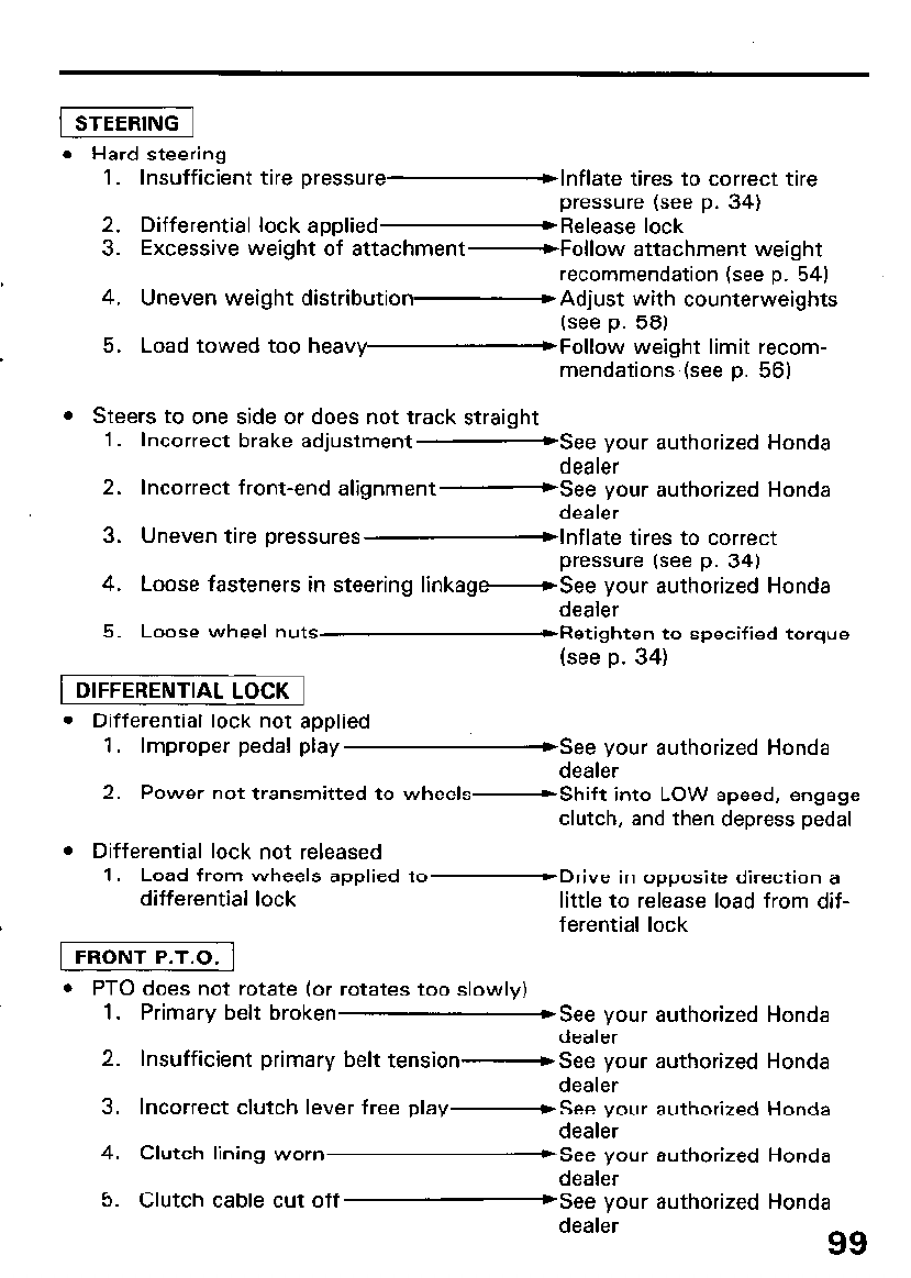
1 STEERING 1
l Hard steering
1. Insufficient tire pressure blnflate tires to correct tire
pressure (see p. 34)
2. Differential lock applied *Release lock
3. Excessive weight of attachment -Follow attachment weight
recommendation (see p. 54)
4. Uneven weight distribution- Adjust with counterweights
(see p. 58)
5. Load towed too heav y~~follow weight limit recom-
mendations (see p. 56)
l Steers to one side or does not track straiaht
1.
2.
3.
4.
5.
Incorrect brake adjustment -See your authorized Honda
dealer
Incorrect front-end alignment- See your authorized Honda
dealer
Uneven tire pressures blnflate tires to correct
pressure (see p. 34)
Loose fasteners in steering linkag -See your authorized Honda
dealer
Loose wheel nuts WRetighten to specified torque
(see p. 34)
1 DIFFERENTIAL LOCK 1
l Differential lock not applied
1. Improper pedal play &ee your authorized Honda
dealer
2. Power not transmitted to wheels- Shift into LOW speed, engage
clutch, and then depress pedal
l Differential lock not released
1. Load from wheels applied to- Drive in opposite direction a
differential lock little to release load from dif-
ferential lock
1 FRONT P.T.O. 1
l PTO does not rotate (or rotates too slowly)
1.
2.
3.
4.
5.
Primary belt broken *See your authorized Honda
dealer
Insufficient primary belt tension- See your authorized Honda
dealer
Incorrect clutch lever free play- See your authorized Honda
dealer
Clutch lining worn WSee your authorized Honda
dealer
Clutch cable cut off )See your authorized Honda
dealer 99
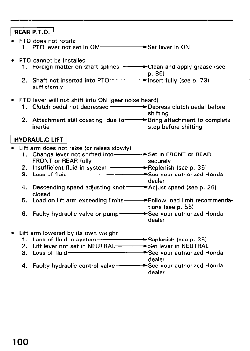
l PTO does not rotate
1. PTO lever not set in ON ,Set lever in ON
l PTO cannot be installed
1. Foreign matter on shaft splines -Clean and apply grease (see
p. 86)
2. Shaft not inserted into PTO- Insert fully (see p. 73)
sufficiently
l PTO lever will not shift into ON (gear noise heard)
1. Clutch pedal not depressed -Depress clutch pedal before
shifting
2. Attachment still coasting due to- Bring attachment to complete
inertia stop before shifting
1 HYDRAULIC LIFT 1
l Lift arm does not raise (or raises slowly)
1. Change lever not shifted into -Set in FRONT or REAR
FRONT or REAR fully securely
2. Insufficient fluid in system- Replenish (see p. 35)
3. Loss of fluid WSee your authorized Honda
dealer
4. Descending speed adjusting knob -Adjust speed (see p. 25)
closed
5. Load on lift arm exceeding limits -Follow load limit recommenda-
tions (see p. 55)
6. Faulty hydraulic valve or pump -See your authorized Honda
dealer
l Lift arm lowered by its own weight
1. Lack of fluid in system WReplenish (see p. 35)
2. Lift lever not set in NEUTRAL- Set lever in NEUTRAL
3. Loss of fluid *See your authorized Honda
dealer
4. Faulty hydraulic control valve -See your authorized Honda
dealer
100
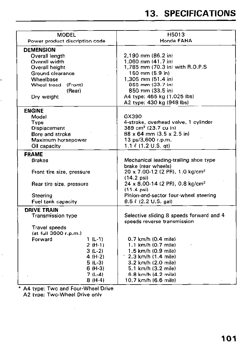
13. SPECIFICATIONS
MODEL H5013
Power product discription code Honda FAHA
DEMENSION
Overall length 2.190 mm (86.2 in)
Overall width 1,060 mm (41.7 in)
Overall height 1,785 mm (70.3 in) with R.0.P.S
Ground clearance 150 mm (5.9 in)
Wheelbase 1,305 mm (51.4 in)
Wheel tread (Front) 855 mm (33.7 in)
(Rear) 850 mm (33.5 in)
Dry weight A4 type: 465 kg (1.025 Ibs)
A2 type: 430 kg (948 Ibs)
ENGINE
Model GX390
Type 4-stroke, overhead valve, 1 cylinder
Displacement 389 cm3 (23.7 cu in)
Bore and stroke 88 x 64 mm (3.5 x 2.5 in)
Maximum horsepower 13 ps13.600 r.p.m.
Oil capacity 1.1 P (1.2 U.S. qt)
FRAME
Brakes Mechanical leading-trailing shoe type
brake (rear wheels)
Front tire size, pressure 20 x 7.00-l 2 (2 PRI, 1 .O kg/cm’
(14.2 psi)
Rear tire size, pressure 24 x 8.00-14 (2 PR), 0.8 kg/cm2
(11.4 psi)
Steering Pinion-and-sector four-wheel steering
Fuel tank capacity 8.5 P (2.2 U.S. gal)
DRIVE TRAIN
Transmission type Selective sliding 8 speeds forward and 4
speeds reverse transmission
Travel speeds
(at full 3800 r.p.m.1
Forward 1 (L-1) 0.7 km/h (0.4 mile)
2 (H-1) 1 .I km/h (0.7 mile) ’
3 (L-2) 1.5 km/h (0.9 mile)
4 (H-2) ’ 2.3 km/h (1.4 mile)
5 (L-3) 3.2 km/h (2.0 mile)
6 (H-3) 5.1 km/h (3.2 mile)
7 (L-4) 6.8 km/h (4.2 mile)
8 (H-4) 10.7 km/h (6.6 mile)
44 type: Two and Four-Wheel Drive
A2 type: Two-Wheel Drive only
101
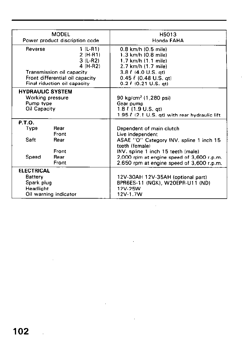
MODEL
Power product discription code
Reverse 1 (L-R11
2 (H-R11
3 (L-R21
4 (H-R21
Transmission oil capacity
Front differential oil capacity
Final riduction oil capacity
HYDRAULIC SYSTEM
Working pressure
Pump type
Oil Capacity
P.T.O.
Tvw Rear
Front
Saft Rear
Front
Speed Rear
Front
ELECTRICAL
Battery
Spark plug
Headlight
Oil warning indicator
H5013
Honda FAHA
0.8 km/h (0.5 mile)
1.3 km/h (0.8 mile)
1.7 km/h (1 .l mile)
2.7 km/h (1.7 mile)
3.8 P (4.0 U.S. qt)
0.45 P (0.48 U.S. qt)
0.2 P (0.21 U.S. qt)
90 kg/cm2 (1,280 psi)
Gear pump
1.8 P (1.9 U.S. qt)
1.95 P (2.1 U.S. qt) with rear hydraulic lift
Dependent of main clutch
Live independent
ASAE “0” Category INV. spline 1 inch 15
teeth (female)
INV. spline 1 inch 15 teeth (male)
2,000 rpm at engine speed of 3,600 r.p.m.
2,650 rpm at engine speed of 3,600 r.p.m.
12V-30AH 12V-35AH (optional part)
BPRGES-11 (NGK), W20EPR-Ul l (ND)
12V-25W
12v-1.7w
102
14. WARRANTY SERVICE
Owner Satisfaction
Your satisfaction and goodwill are important to your dealer and to us. All
Honda warranty details are explained in the Distributor’s Limited Warran-
ty. Normally, any problems concerning the product will be handled by your
dealer’s service department. If you have a warranty problem that has not
been handled to your satisfaction, we suggest you take the following
action:
l Discuss your problem with a member of dealership managemert. Often
complaints can be quickly resolved at that level. If the problem has
already been reviewed with the Service Manager, contact the owner of
the dealership or the General Manager.
l If your problem still has not been resolved to your satisfaction, contact:
American Honda Motor Co., Inc.
P.O. Box 50
Gardena, California 90247-0805
Telephone: (213) 604-2400
We will need the following information in order to assist you:
- Your name, address, and telephone number
- Product model and serial number
- Date of Purchase
- Dealer name and address
- Nature of problem
After reviewing all the facts involved, you will be advised of what action
can be taken. Please bear in mind that your problem will likely be resolved
at the dealership, using the dealer’s facilities, equipment, and personnel,
so it is very important that your initial contact be with the dealer.
Your purchase of a Honda product is greatly appreciated by both your
dealer and American Honda Motor Co., Inc. We want to assist you in every
way possible to assure your complete satisfaction with your purchase.
103
Current customer service contact information:
United States, Puerto Rico, and U.S. Virgin Islands:
Honda Power Equipment dealership personnel are trained professionals. They should
be able to answer any question you may have. If you encounter a problem that your
dealer does not solve to your satisfaction, please discuss it with the dealership's
management. The Service Manager or General Manager can help. Almost all problems
are solved in this way.
If you are dissatisfied with the decision made by the dealership's management, contact
the Honda Power Equipment Customer Relations Office. You can write:
American Honda Motor Co., Inc.
Power Equipment Division
Customer Relations Office
4900 Marconi Drive
Alpharetta, GA 30005-8847
Or telephone: (770) 497-6400 M-F, 8:30 am - 7:00 pm EST
When you write or call, please provide the following information:
• Model and serial numbers
• Name of the dealer who sold the Honda power equipment to you
• Name and address of the dealer who services your equipment
• Date of purchase
• Your name, address, and telephone number
• A detailed description of the problem

MEMO