Honda Hs624 Users Manual
HS624 74e3de14-d5c5-4ab5-b93e-5224d048e9d7
2015-03-12
: Honda Honda-Hs624-Users-Manual-657409 honda-hs624-users-manual-657409 honda pdf
Open the PDF directly: View PDF ![]() .
.
Page Count: 53
©1992 Honda Motor Co., Ltd.—All Rights Reserved
Owner's Manual
HS624 • HS828
Thank you for purchasing a Honda snowblower. We want to help you get
the best results from your new snowblower and to operate it safely. This
manual contains the information on how to do that; please read it carefully.
This owner’s manual describes the operation and maintenance of Honda
snowblower:
HS624/HS828
All information in this publication is based on the latest product
information available at the time of printing. Honda Motor Co., Ltd.
reserves the right to make changes at any time without notice and
without incurring any obligation. No part of this publication may be
reproduced without written permission.
This manual should be considered a permanent part of the snowblower
and should remain with it if it is resold.
Safety Messages
Your safety and the safety of others is very important. We have provided
important safety messages in this manual and on the snowblower. Please
read these messages carefully.
A safety message alerts you to potential hazards that could hurt you or
others. Each safety message is preceded by a safety alert symbol
A and one of three words: DANGER, WARNING, or CAUTION.
These mean
m You WILL be KILLED or SERIOUSLY HURT if you don’t follow
instructions.
B You CAN be KILLED or SERIOUSLY HURT if you don’t
follow instructions.
B You CAN be HURT if you don’t follow instructions.
Each message tells you what the hazard is, what can happen, and what
you can do to avoid or reduce injury.
Damage Prevention Messages
You will also see other important messages that are preceded by the word
NOTICE.
This word means:
/TzEiq y our snbwblower or other property could be damaged if you
don’t follow instructions.
The purpose of these messages is to help prevent damage to your
snowblower, other property, or the environment.
1
CONTENTS
SAFETY ................................................................................................................ 3
Safety Label Locations ................................................................................... 3
Safety Information ......................................................................................... .4
COMPONENT IDENTIFICATION.. ...................................................................... .7
CONTROLS ......................................................................................................... .9
Engine switch .................................................................................................. .9
Fuel valve.. ....................................................................................................... .9
Fuel gauge ....................................................................................................... 10
Chute crank ................................................................................................... 10
Starter grip .......................................... . ......................................................... .l 1
Throttle lever(Engine speed) ....................................................................... .l 1
Shift lever ...................................................................................................... .12
Chute guide ................................................................................................... .12
Drive clutch lever and auger clutch lever .................................................... 13
Skid plate, scraper ....................................................................................... .14
Foot pedal ....................................................................................................... 15
Transmission release lever.. ........................................................................ .16
PRE-OPERATION CHECK.. .............................................................................. .17
Fuel recommendation ................................................................................... 17
Engine oil ......................................................................................................... 19
Hydrostatic transmission fluid ..................................................................... 20
Auger and blower bolts.. .............................................................................. .21
Other checks.. ............................................................................................... .21
STARTING THE ENGINE .................................................................................. .22
SNOW BLOWER OPERATION ......................................................................... .27
Clearing snow ............................................................................................... .30
STOPPING THE ENGINE .................................................................................. .32
MAINTENANCE ................................................................................................ .34
Maintenance schedule ................................................................................. .35
Tool kit.. ......................................................................................................... .36
Engine oil change ........................................................................................... 37
Spark plug service ......................................................................................... 38
Track-adjustment ......................................................................................... .39
Wheel/Tire inspection.. ................................................................................ .40
Auger/Blower inspection.. ........................................................................... .41
TRANSPORTING .............................................................................................. .42
Before loading ............................................................................................... .42
Loading .......................................................................................................... .42
STORAGE .......................................................................................................... 44
TROUBLESHOOTING.. ..................................................................................... .47
SPECIFICATIONS ............................................................................................. .48
COSTOMER SERVICE INFORMATION .......................................................... .50
INDEX ................................................................................................................. 51
2
SAFETY
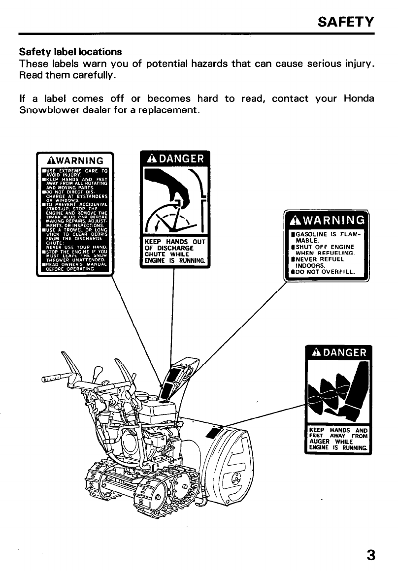
Safety label locations
These labels warn you of potential hazards that can cause serious injury.
Read them carefully.
If a label comes off or becomes hard to read, contact your Honda
Snowblower dealer for a replacement.
3
Safety information
To ensure safe operation
l Always make a pre-operation check (pages 17 thru 21 1 before you
start the engine. You may prevent an accident or equipment damage.
l Honda snowblowers are designed to give safe and dependable service
if operated according to instructions. Read and understand this Owner’s
Manual before operating the snowblower. Failure to do so could result
in personal injury or equipment damage.
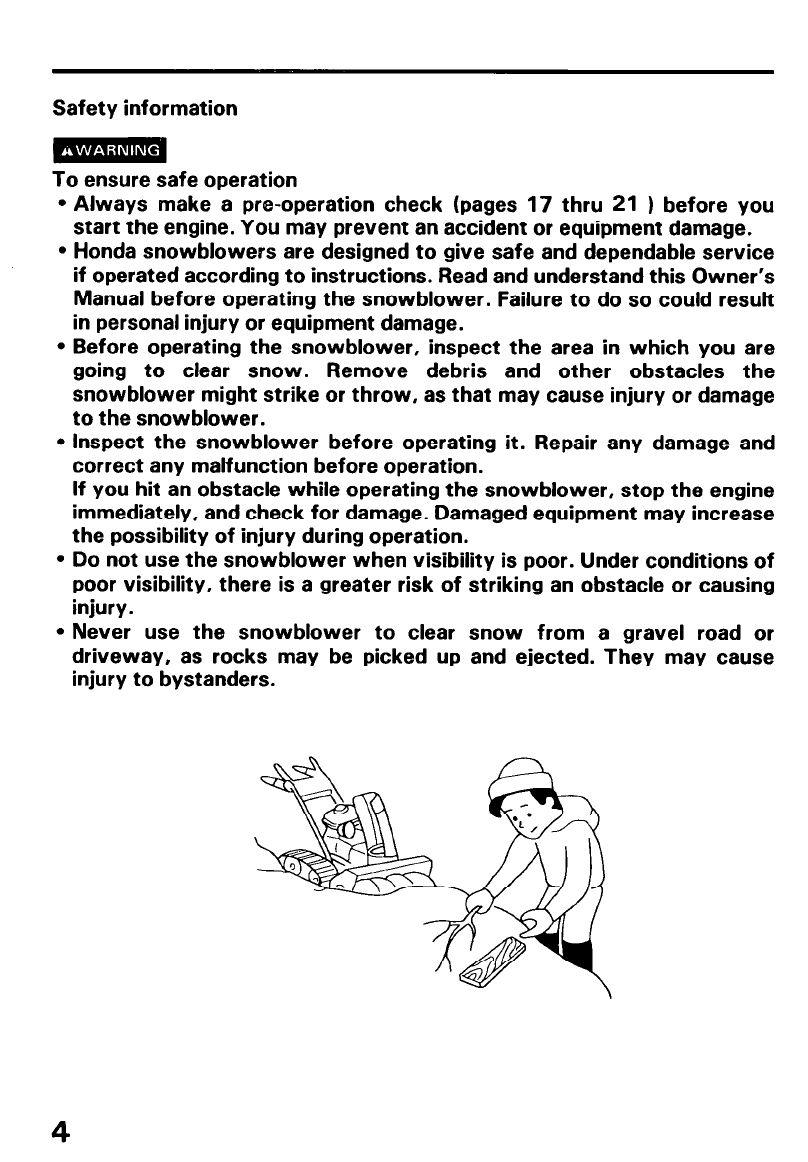
l Before operating the snowblower, inspect the area in which you are
going to clear snow. Remove debris and other obstacles the
snowblower might strike or throw, as that may cause injury or damage
to the snowblower.
l Inspect the snowblower before operating it. Repair any damage and
correct any malfunction before operation.
If you hit an obstacle while operating the snowblower, stop the engine
immediately, and check for damage. Damaged equipment may increase
the possibility of injury during operation.
l Do not use the snowblower when visibility is poor. Under conditions of
poor visibility, there is a greater risk of striking an obstacle or causing
injury.
l Never use the snowblower to clear snow from a gravel road or
driveway, as rocks may be picked up and ejected. They may cause
injury to bystanders.
4
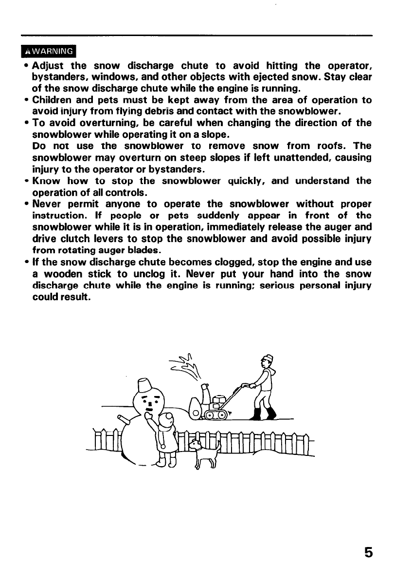
l Adjust the snow discharge chute to avoid hitting the operator,
bystanders, windows, and other objects with ejected snow. Stay clear
of the snow discharge chute while the engine is running.
l Children and pets must be kept away from the area of operation to
avoid injury from flying debris and contact with the snowblower.
l To avoid overturning, be careful when changing the direction of the
snowblower while operating it on a slope.
Do not use the snowblower to remove snow from roofs. The
snowblower may overturn on steep slopes if left unattended, causing
injury to the operator or bystanders.
l Know how to stop the snowblower quickly, and understand the
operation of all controls.
l Never permit anyone to operate the snowblower without proper
instruction. If people or pets suddenly appear in front of the
snowblower while it is in operation, immediately release the auger and
drive clutch levers to stop the snowblower and avoid possible injury
from rotating auger blades.
l If the snow discharge chute becomes clogged, stop the engine and use
a wooden stick to unclog it. Never put your hand into the snow
discharge chute while the engine is running; serious personal injury
could result,
5
l Gasoline is extremely flammable and is explosive under certain
conditions.
Do not smoke or allow flames or sparks where the snowblower is
refueled or where gasoline is stored. Allow the engine to cool down
before refueling.
Refuel in a well-ventilated area with the engine stopped.
Do not overfill the fuel tank, and make sure the filler cap is closed
securely after refueling.
l Never run the engine in an enclosed or confined area. Exhaust contains
poisonous carbon monoxide gas; exposure can cause loss of
consciousness and may lead to death.
l The muffler becomes very hot during operation and remains hot for a
while after stopping the engine. Be careful not to touch the muffler
while it is hot. Let the engine cool before storing the snowblower
indoors.
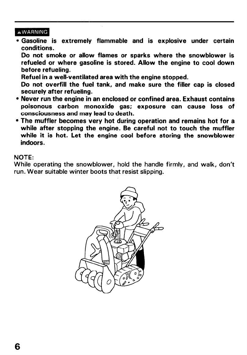
NOTE:
While operating the snowblower, hold the handle firmly, and walk, don’t
run. Wear suitable winter boots that resist slipping.
6
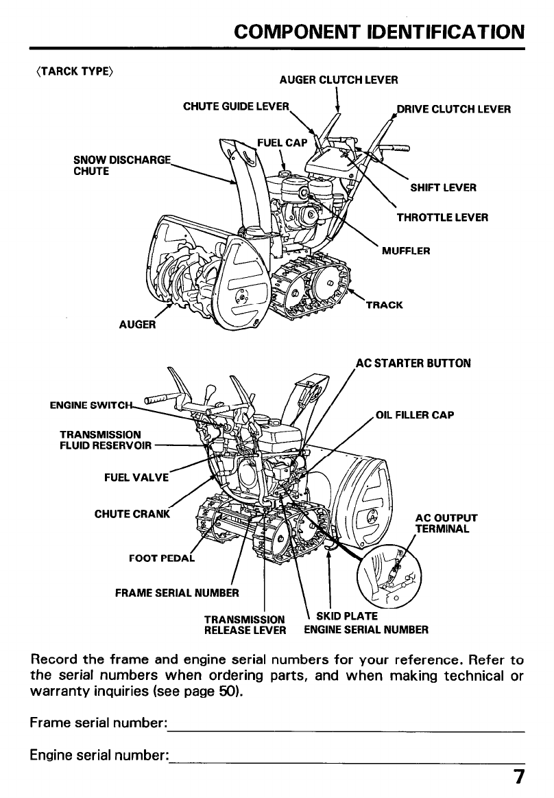
COMPONENT IDENTIFICATION
(TARCK TYPE) AUGER CLUTCH LEVER
CHUTE GUIDE LEVER DRIVE CLUTCH LEVER
SNOW DISCHARGE
CHUTE
\lF-ET-f rs-- -SHIFT LEVER
TRACK
& THROTTLE LEVER
r ’ MUFFLER
AC STARTER BUTTON
FUEL VALVE- 2
CHUTE CRAN UT
L
TRANSMISSION
FLUID RESERVOIR
OIL FILLER CAP
FRAME SERlAL NUMBER
RELEASE LEVER ENGINE SERIAL NUMBER
Record the frame and engine serial numbers for your reference. Refer to
the serial numbers when ordering parts, and when making technical or
warranty inquiries (see page 50).
Frame serial number:
Engine serial number:
7
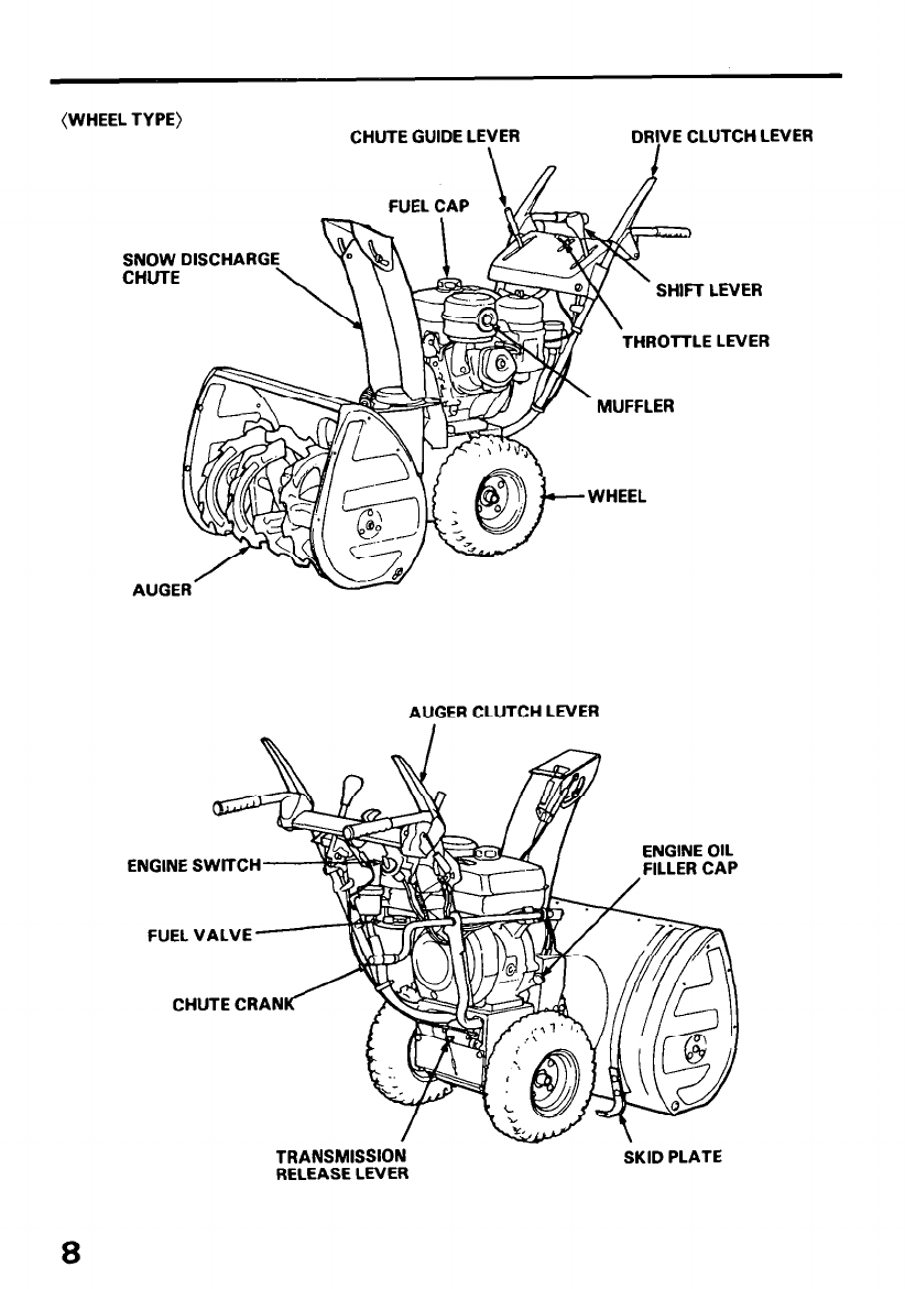
(WHEEL TYPE) CHUTE GUIDE LE;ER DR!VE CLUTCH LEVER
SNOW DISCHARG
THROTTLE LEVER
AUGER CLUTCH LEVER
ENGINE SWlTCH
FUEL VALVE
CHUTE CRAN
TRANSMISSION
RELEASE LEVER SKID PLATE
8
CONTROLS
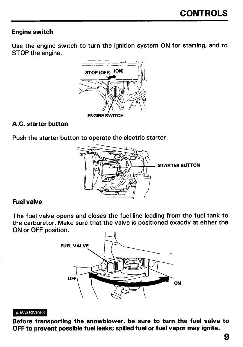
Engine switch
Use the engine switch to turn the ignition system ON for starting, and to
STOP the engine.
A.C. starter button
ENGINE SWITCH
Push the starter button to operate the electric starter.
STARTER BUTTON
Fuel valve
The fuel valve opens and closes the fuel line leading from the fuel tank to
the carburetor. Make sure that the valve is positioned exactly at either the
ON or OFF
ON
Before transporting the snowblower, be sure to turn the fuel valve
OFF to prevent possible fuel leaks; spilled fuel or fuel vapor may ignite.
to
9
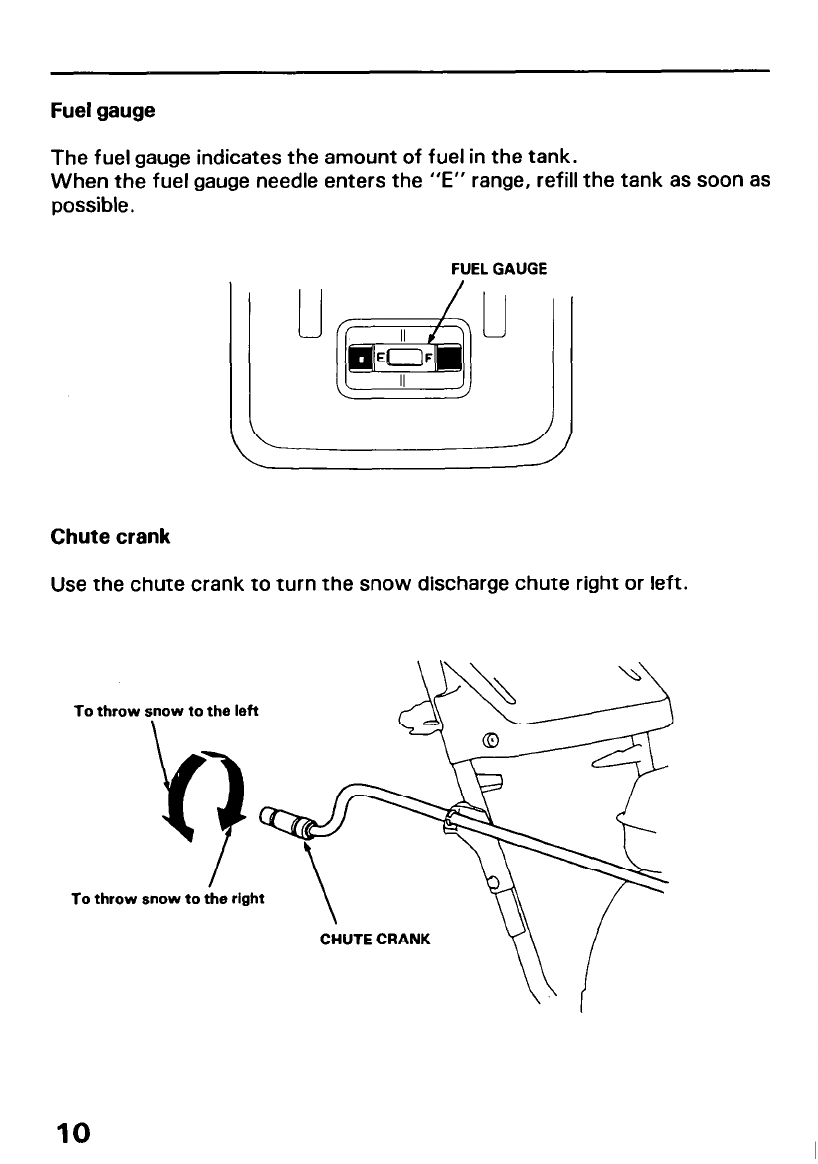
Fuel gauge
The fuel gauge indicates the amount of fuel in the tank.
When the fuel gauge needle enters the “E” range, refill the tank as soon as
possible.
FUEL GAUGE
Chute crank
Use the chute crank to turn the snow discharge chute right or left.
To throw snow to the left
9
To throw snow to the right
CHUTE CRANK
10
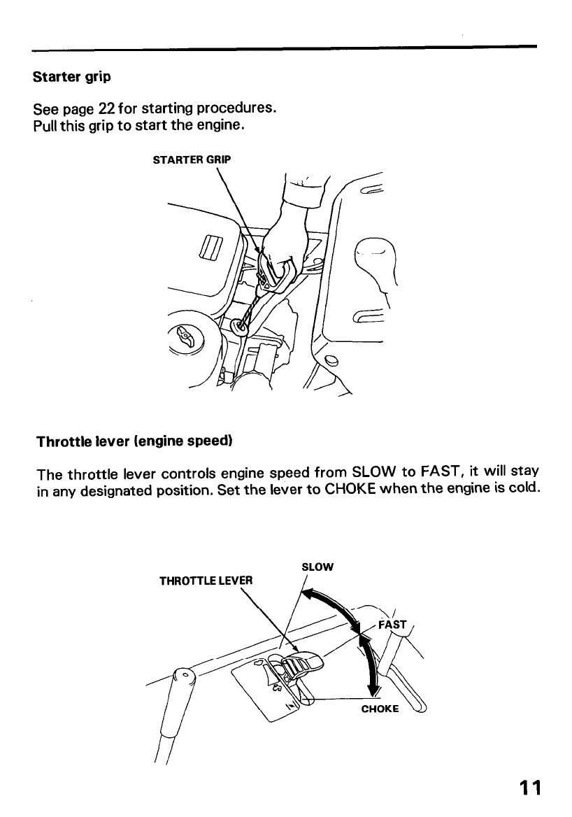
Starter grip
See page 22 for starting procedures.
Pull this grip to start the engine.
STARTER GRIP
Throttle lever (engine speed)
The throttle lever controls engine speed from SLOW to FAST, it will stay
in any designated position. Set the lever to CHOKE when the engine is cold.
SLOW
THROTTLE LEVER
11
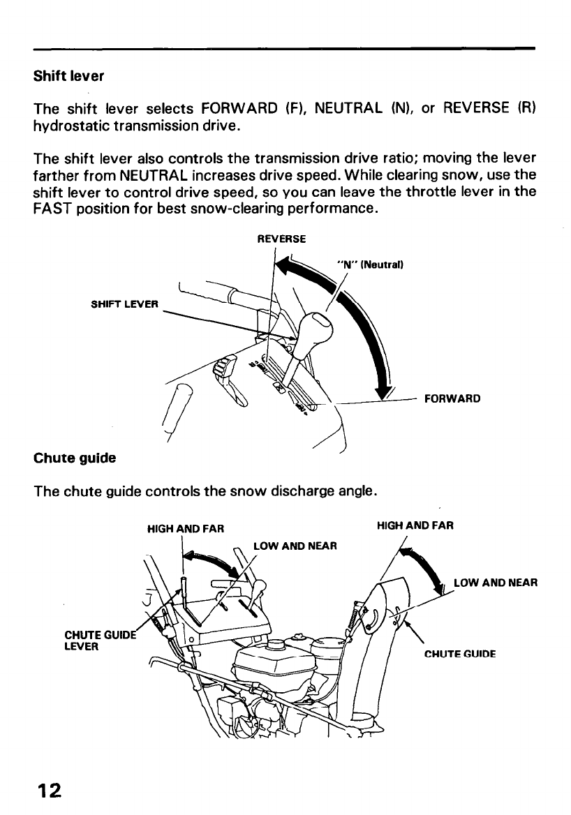
Shift lever
The shift lever selects FORWARD (F), NEUTRAL (N), or REVERSE (RI
hydrostatic transmission drive.
The shift lever also controls the transmission drive ratio; moving the lever
farther from NEUTRAL increases drive speed. While clearing snow, use the
shift lever to control drive speed, so you can leave the throttle lever in the
FAST position for best snow-clearing performance.
REVERSE
SHIFT LRlER
FORWARD
Chute guide
The chute guide controls the snow discharge angle.
HIGH AND FAR HIGH AND FAR
CHUTE
LEVER
OW AND NEAR
LOW AND NEAR
GUID
CHUTE GUIDE
12
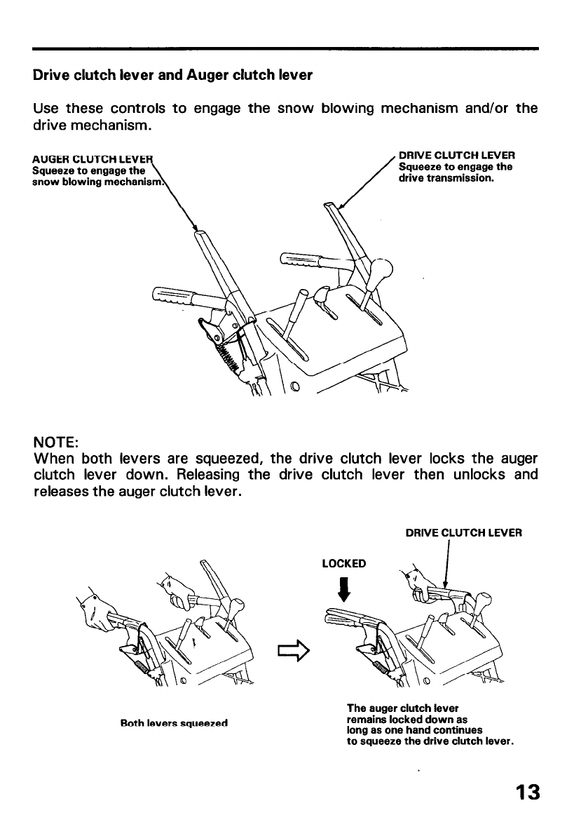
Drive clutch lever and Auger clutch lever
Use these controls to engage the snow blowing mechanism and/or the
drive mechanism.
AUGER CLUTCH LEVE
Squeeze to engage the
snow blowing mechani
DRNE CLUTCH LEVER
Squeeze to engage the
drive transmission.
NOTE:
When both levers are squeezed, the drive clutch lever locks the auger
clutch lever down. Releasing the drive clutch lever then unlocks and
releases the auger clutch lever.
DRIVE CLUTCH LEVER
Both levers squeezed
The auger clutch lever
remains locked down as
long as one hand continues
to squeeze the drive clutch lever.
13

Skid plate, scraper
Adjust the skid plates for the auger ground clearance best suited to your
snow removal conditions.
To prevent accidental starting, turn the engine switch to the OFF position
and disconnect the spark plug cap.
1 .Place the snow thrower on a level surface and set the height adjustment
pedal in the middle position.,
2.Move the skid plates up or down to obtain the desired auger ground
clearance.
For ordinary snow: 4.0-8.0 mm (0.16-0.31 in)
For finishing: 0- 5 mm (O-0.20 in)
For use on uneven surfaces: 25.0-30.0 mm (0.98- 1 .18 in)
3. Adjust the scraper ground clearance to: 2.0-4.0 mm (0.08-0.16 in)
Au~:;a~~~~~~D~~~
2.0--4.Omm SCRAPER
(O.OB-0.16ln)
NOTE:
Adjust the skid plates equally on both sides.
Be sure to tighten the skid plate and scraper bolts securely after making
adjustments.
Do not use the snowblower on rough or uneven surfaces with the auger
ground clearance set for ordinary snow or finishing conditions. This may
cause serious damage to the snow throwing mechanism.
14

Foot pedal (Track type only)
Use the pedal for adjusting the height and angle of the machine in relation
to the tracks.
1. Hold the handles and step on the pedal.
2. Raise or lower the machine to the desired position and release the pedal.
LOW : Hard snow or fine finish
MIDDLE : Normal use
HIGH : Deep snow or for transporting the snowblower.
HIGH
MIDDLE
LOW
FOOT PEDAL
15
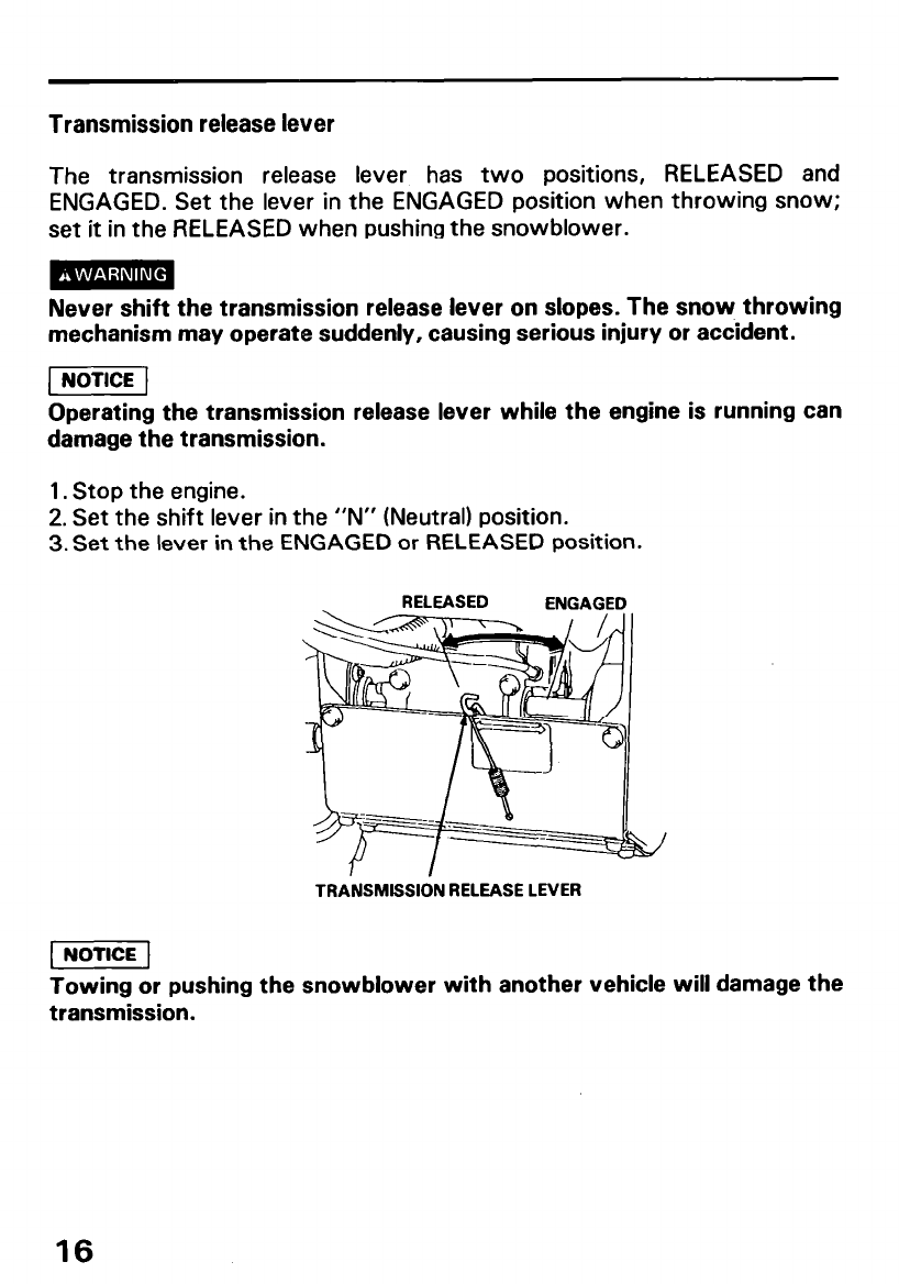
Transmission release lever
The transmission release lever has two positions, RELEASED and
ENGAGED. Set the lever in the ENGAGED position when throwing snow;
set it in the RELEASED when pushing the snowblower.
Never shift the transmission release lever on slopes. The snow throwing
mechanism may operate suddenly, causing serious injury or accident.
Operating the transmission release lever while the engine is running can
damage the transmission.
1. Stop the engine.
2. Set the shift lever in the “N” (Neutral) position.
3. Set the lever in the ENGAGED or RELEASED position.
RELEASED ENGAGED
TRANSMISSION RELEASE LEVER
Towing or pushing the snowblower with another vehicle will damage the
transmission.
16
PRE-OPERATION CHECK
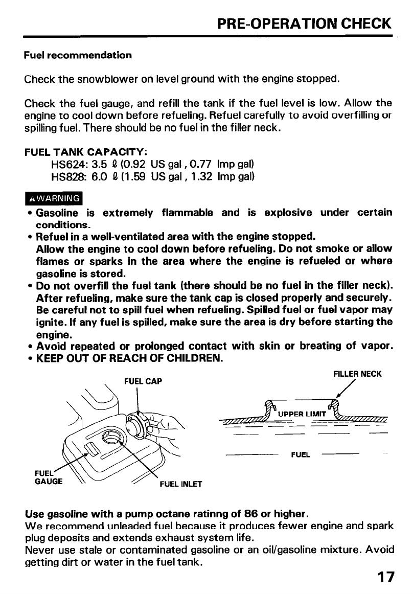
Fuel recommendation
Check the snowblower on level ground with the engine stopped.
Check the fuel gauge, and refill the tank if the fuel level is low. Allow the
engine to cool down before refueling. Refuel carefully to avoid overfilling or
spilling fuel. There should be no fuel in the filler neck.
FUEL TANK CAPACITY:
HS624: 3.5 0 (0.92 US gal, 0.77 Imp gal)
HS828: 6.0 0 (1.59 US gal , 1.32 Imp gal)
l Gasoline is extremely flammable and is explosive under certain
conditions.
l Refuel in a well-ventilated area with the engine stopped.
Allow the engine to cool down before refueling. Do not smoke or allow
flames or sparks in the area where the engine is refueled or where
gasoline is stored.
l Do not overfill the fuel tank (there should be no fuel in the filler neck).
After refueling, make sure the tank cap is closed properly and securely.
Be careful not to spill fuel when refueling. Spilled fuel or fuel vapor may
ignite. If any fuel is spilled, make sure the area is dry before starting the
engine.
l Avoid repeated or prolonged contact with skin or breating of vapor.
l KEEP OUT OF REACH OF CHILDREN.
FILLER NECK
J
FUEL -
Use gasoline with a pump octane ratinng of 86 or higher.
We recommend unleaded fuel because it produces fewer engine and spark
plug deposits and extends exhaust system life.
Never use stale or contaminated gasoline or an oil/gasoline mixture. Avoid
getting dirt or water in the fuel tank.
17
Occasionally you may hear light “spark knock” or “pinging” (metallic
rapping noise) while operating under heavy loads. This is no cause for
concern.
lf spark knock or pinging occurs at a steady engine speed, under normal
load, change brands of gasoline. If spark knock or pinging persists, see an
authorized Honda snowblower dealer.
pEiq
Running the engine with persistent spark knock or pinging can cause
engine damage.
Running the engine with persistent spark knock or pinging is misuse, and
the Distributor’s Limited Warranty does not cover parts damaged by
misuse.
Oxygenated Fuels
Some conventional gasolines are being blended with alcohol or an ether
compound. These gasolines are collectively referred to as oxygenated
fuels. To meet clean air standards, some areas of the United States and
Canada use oxygenated fuels to help reduce emissions.
ff you use an oxygenated fuel, be sure it is unleaded and meets the
minimum octane rating requirement.
Before using an oxygenated fuel, try to confirm the fuel’s contents. Some
states/provinces require this information to be posted on the pump.
The following are the EPA-approved percentages of oxygenates:
Ethanol (ethyl or grain alcohol)
You may use gasoline containing up to 10% ethanol by volume. Gasoline
containing ethanol may be marketed under the name “Gasohol”.
MTBE (methyl tertiary butyl ether)
You may use gasoline containing up to 15% MTBE by volume.
METHANOL (methyl or wood alcohol)
You may use gasoline containing up to 5% methanol by volume as long as
it also contains cosolvents and corrosion inhibitors to protect the fuel
system.
Gasoline containing more than 5% methanol by volume may cause starting
and/or performance problems. lt may also damage metal, rubber, and
plastic parts of your fuel system.
tf you notice any undesirable operating symptoms, try another service
station or switch to another brand of gasoline.
Fuel system damage or performance problems resulting from the use of an
oxygenated fuel containing more than the percentages of oxygenates
given above are not covered under warranty.
18
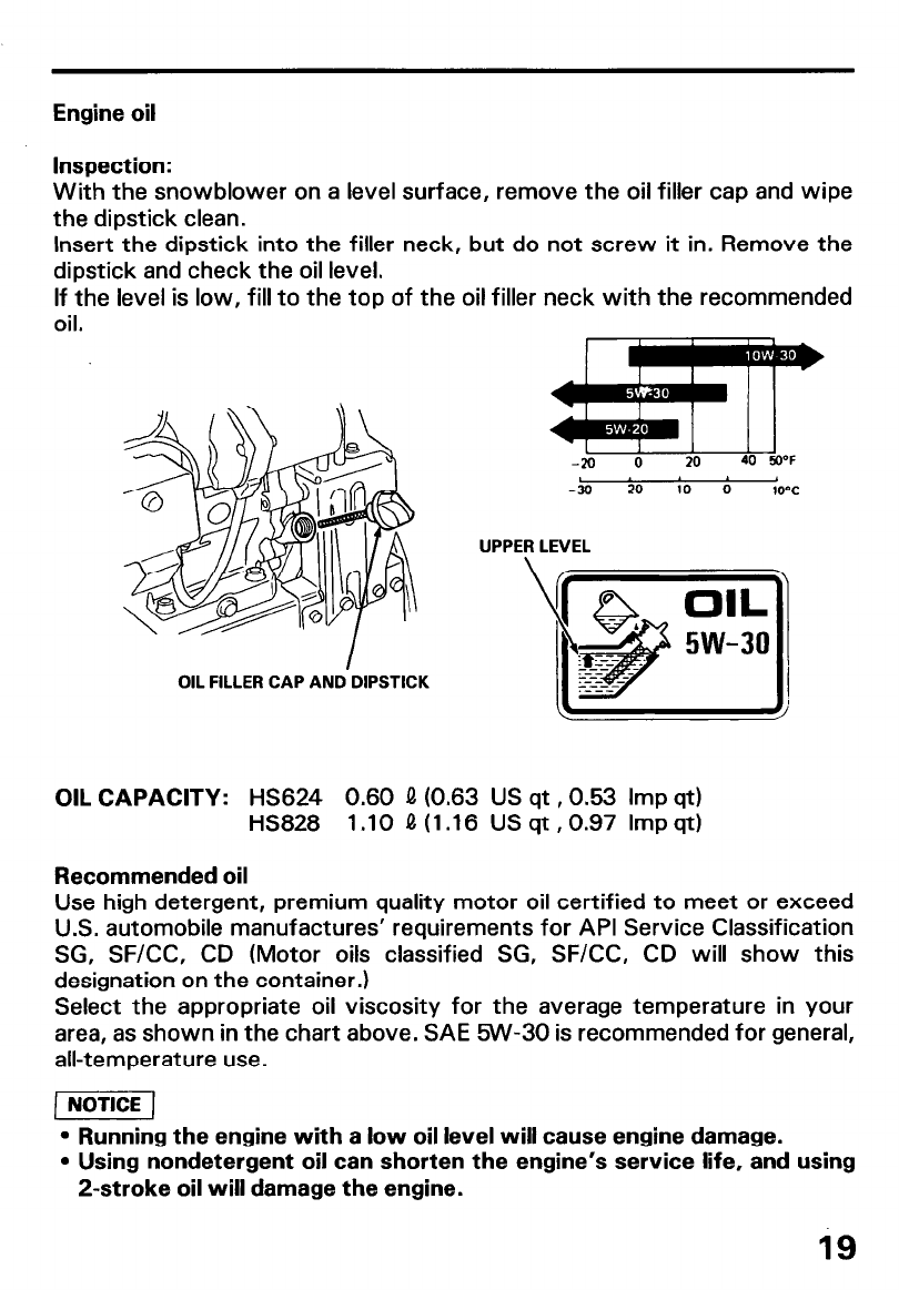
Engine oil
Inspection:
With the snowblower on a level surface, remove the oil filler cap and wipe
the dipstick clean.
Insert the dipstick into the filler neck, but do not screw it in. Remove the
dipstick and check the oil level.
If the level is low, fill to the top of the oil filler neck with the recommended
oil.
OIL FILLER CAP AND.DIPSTICK
L I 1
-20 0 20 40 50-F
-30 -20 -10 0 1ov
UPPER LEVEL
\/
OIL CAPACITY: HS624 0.60 4 (0.63 US qt ,0.53 Imp qt)
HS828 1.10 Q(1.16 USqt,0.97 Impqt)
Recommended oil
Use high detergent, premium quality motor oil certified to meet or exceed
U.S. automobile manufactures’ requirements for API Service Classification
SG, SF/CC, CD (Motor oils classified SG, SF/CC, CD will show this
designation on the container.)
Select the appropriate oil viscosity for the average temperature in your
area, as shown in the chart above. SAE RN-30 is recommended for general,
all-temperature use.
l Running the engine with a low oil level will cause engine damage.
l Using nondetergent oil can shorten the engine’s service life, and using
2-stroke oil will damage the engine.
is
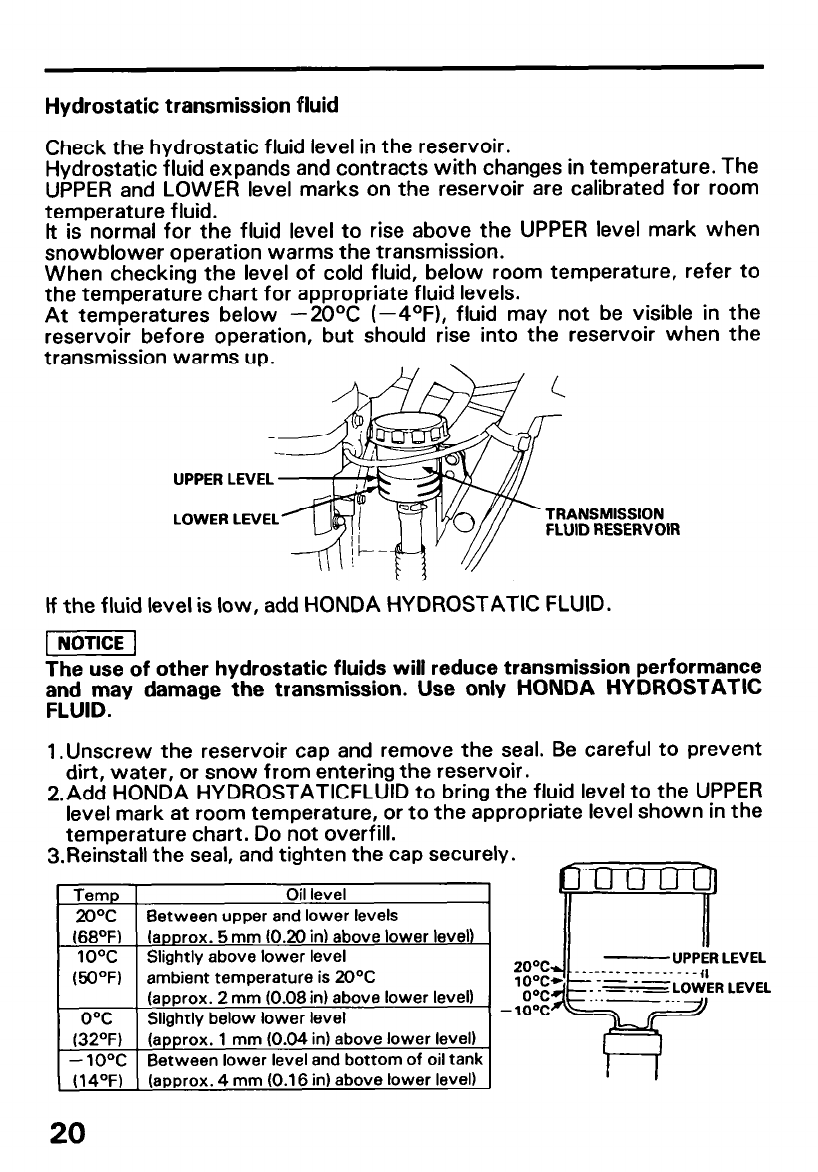
Hydrostatic transmission fluid
Check the hydrostatic fluid level in the reservoir.
Hydrostatic fluid expands and contracts with changes in temperature. The
UPPER and LOWER level marks on the reservoir are calibrated for room
temperature fluid.
lt is normal for the fluid level to rise above the UPPER level mark when
snowblower operation warms the transmission.
When checking the level of cold fluid, below room temperature, refer to
the temperature chart for appropriate fluid levels.
At temperatures below -2OOC (--4OF), fluid may not be visible in the
reservoir before operation, but should rise into the reservoir when the
transmission warms up.
UPPER LEVEL
LOWER LEVEL TRANSMISSION
FLUID RESERVOIR
If the fluid level is low, add HONDA HYDROSTATIC FLUID.
[]
The use of other hydrostatic fluids will reduce transmission performance
ZW&EI~ damage the transmission. Use only HONDA HYDROSTATIC
1 .Unscrew the reservoir cap and remove the seal. Be careful to prevent
dirt, water, or snow from entering the reservoir.
2.Add HONDA HYDROSTATICFLUID to bring the fluid level to the UPPER
level mark at room temperature, or to the appropriate level shown in the
temperature chart. Do not overfill.
3.Reinstall the seal, and tighten the cap securely.
Temp Oil level
2OT Between upper and lower levels
(66OF) (approx. 5 mm (0.20 in) above lower level)
10% Slightly above lower level
(50°F) ambient temperature is 20°C
(approx. 2 mm (0.08 in) above lower level) . ..- __.
OT Slightly below lower level
(32“F) (approx. 1 mm (0.04 in) above lower level)
- 10°C Between lower level and bottom of oil tank
(14°F) (approx. 4 mm (0.16 in) above lower level)
20

Auger and blower bolts
Check the auger and blower for loose or broken bolts. If broken, replace
them with new ones (page 41 1.
BLOWER SHEAR @OLT
AUGER SHEAR BOLT
Other checks
1. Check all bolts, nuts and other fasteners for security.
2. Check each part for operation.
3.Check the entire machine for any other faults which might have been
B caused in previous operation.
21
STARTING THE ENGINE
Never run the engine in an enclosed or confined area. Exhaust contains
poisonous carbon monoxide gas; exposure can cause loss of
consciousness and may lead to death.
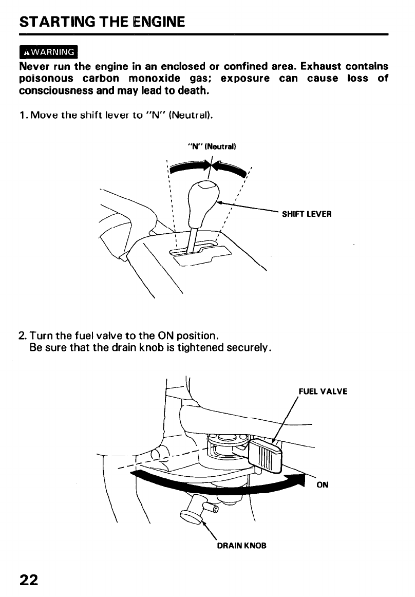
1. Move the shift lever to “N” (Neutral).
“N” (Neutral)
2. Turn the fuel valve to the ON position.
Be sure that the drain knob is tightened securely.
FUEL VALVE
ON
DRAIN KNOB
22
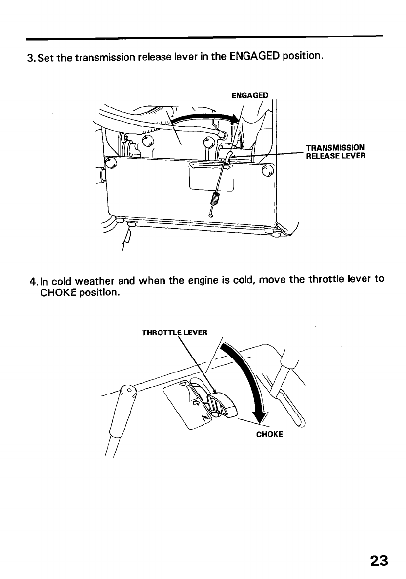
3. Set the transmission release lever in the ENGAGED position.
ENGAGED
TRANSMISSION
RELEASE LEVER
4.ln cold weather and when the engine is cold, move the throttle lever to
CHOKE position.
THROTTLE LEVER
23
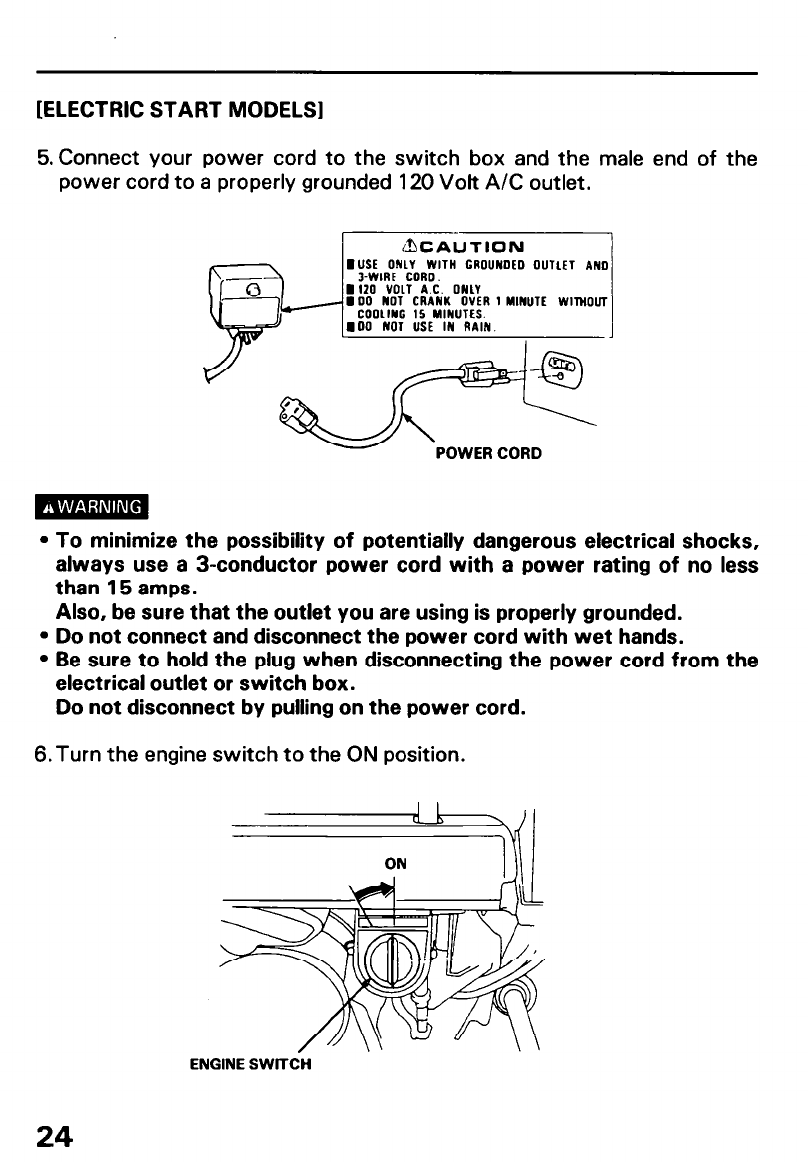
[ELECTRIC START MODELS1
5. Connect your power cord to the switch box and the male end of the
power cord to a properly grounded 120 Volt A/C outlet.
- POWER CORD
l To minimize the possibility of potentially dangerous electrical shocks,
always use a 3-conductor power cord with a power rating of no less
than 15 amps.
Also, be sure that the outlet you are using is properly grounded.
l Do not connect and disconnect the power cord with wet hands.
l Be sure to hold the plug when disconnecting the power cord from the
electrical outlet or switch box.
Do not disconnect by pulling on the power cord.
6.Turn the engine switch to the ON position.
ENGINE SWlTdH
24
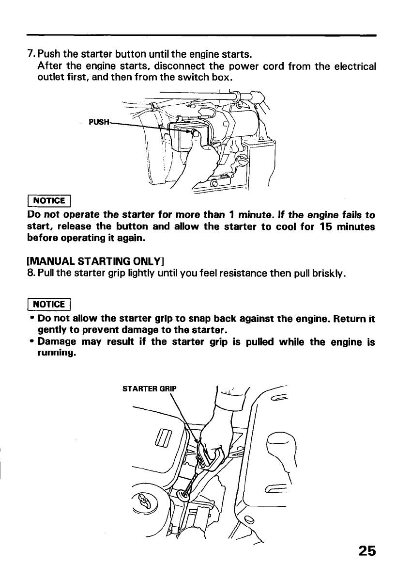
7. Push the starter button until the engine starts.
After the engine starts, disconnect the power cord from the electrical
outlet first, and then from the switch box.
PUSH
Do not operate the starter for more than 1 minute. It the engl
start, release the button and allow the starter to cool for 15 mi
before operating it again.
ine fails
- Inul
to
tes
[MANUAL STARTING ONLY I
8. Pull the starter grip lightly until you feel resistance then pull briskly.
l Do not allow the starter grip to snap back against the engine. Return it
gently to prevent damage to the starter.
l Damage may result if the starter grip is pulled while the engine is
running.
25
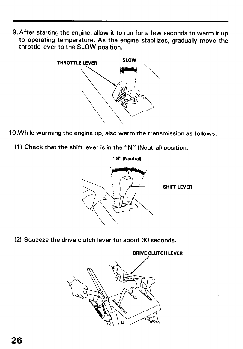
9. After starting the engine, allow it to run for a few seconds to warm it up
to operating temperature. As the engine stabilizes, gradually move the
throttle lever to the SLOW position.
THROTTLE LEVER
lO.While warming the engine up, also warm the transmission as follows:
(1) Check that the shift lever is in the “N” (Neutral) position,
“N” (Neutral)
SHIFT LEVER
(2) Squeeze the drive clutch lever for about 30 seconds.
DRNE CLUTCH LEVER
26
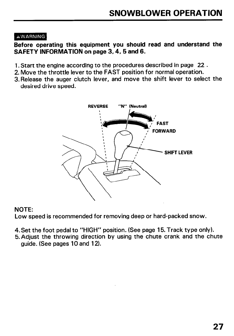
SNOWBLOWER OPERATION
Before operating this equipment you should read and understand the
SAFETY INFORMATION on page 3,4,5 and 6.
1. Start the engine according to the procedures described in page 22 .
2. Move the throttle lever to the FAST position for normal operation.
3.Release the auger clutch lever, and move the shift lever to select the
desired drive speed.
REVERSE “N” (Neutral)
’ LEVER
NOTE:
Low speed is recommended for removing deep or hard-packed snow.
4. Set the foot pedal to “HIGH” position. (See page 15. Track type only).
5.Adjust the throwing direction by using the chute crank and the chute
guide. (See pages 10 and 12).
27

6. Squeeze the auger clutch lever.
The machine will clear snow when you squeeze the auger clutch lever.
AUGER CLUTCH LEVER
7. Squeeze the drive clutch lever.
If the transmission release lever (p. 23) is in the ENGAGED position, and
the shift lever (p. 27) is in the FORWARD (F) position, the hydrostatic
drive will propel the snowblower forward when you squeeze the drive
clutch lever.
DRIVE CLUTCH
LEVER
When both levers are squeezed, the drive clutch lever locks the auger
clutch lever down. This frees your right hand to operate the other
snowblower controls. Releasing the drive clutch lever unlocks and releases
the auger clutch lever.
28
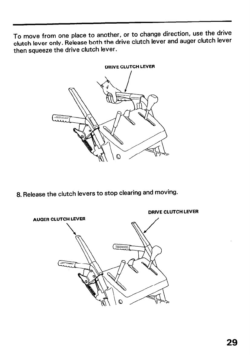
To move from one place to another, or to change direction, use the drive
clutch lever only. Release both the drive clutch lever and auger clutch lever
then squeeze the drive clutch lever.
DRIVE CLUTCH LEVER
8. Release the clutch levers to stop clearing and moving.
DRIVE CLUTCH
AUGER CLUTCH LEVER
LEVER
29
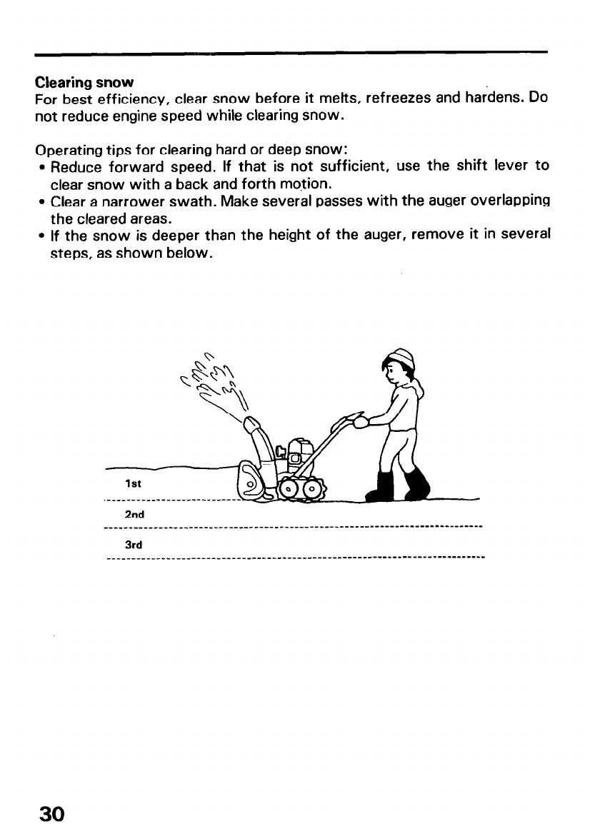
Clearing snow
For best efficiency, clear snow before it melts, refreezes and hardens. Do
not reduce engine speed while clearing snow.
Operating tips for clearing hard or deep snow:
l Reduce forward speed. If that is not sufficient, use the shift lever to
clear snow with a back and forth motion.
l Clear a narrower swath. Make several passes with the auger overlapping
the cleared areas.
l If the snow is deeper than the height of the auger, remove it in several
steps, as shown below.
.-_-_---------___----------
2nd
____-_______________---------------------------------------------.----------
3rd
____________________--------------------------------------------------------
30

l Adjust the snow discharge chute to avoid hitting the operator,
bystanders, windows, and other objects with thrown snow. Stay clear
of the snow discharge chute while the engine is running.
l If the snow discharge chute becomes clogged, stop the engine and use
a wooden stick to unclog it. Never put your hand into the snow
discharge chute while the engine is running; serious personal injury
could result.
l To move from one place to another, or to change direction, use the
drive clutch lever. Using the auger clutch lever will cause the
snowblowing mechanism to rotate, possibly resulting in equipment
damage or personal injury.
High altitude operation
At high altitude, the standard carburetor air-fuel mixture will be too rich.
Performance will decrease, and fuel consumption will increase.
A very rich mixture will also foul the spark plug, cause hard starting and
contribute to air pollution.
High altitude performance can be improved by installing a smaller diameter
main fuel jet in the carburetor and readjusting the pilot screw. If you always
operate the engine at altitudes higher than 1,600 meters (6,000 feet) above
sea level, have an authorized Honda Snowblower dealer perform this
carburetor modifications.
Even with suitable carburetor jetting, engine horsepower will decrease
approximately 3.5 % for each 300 meter (1,000 feet) increase in altitude.
The effect of altitude on horsepower will be greater than this if no
carburetor modification is made. A reduction in engine horsepower will
reduce pumping performance.
When the carburetor is modified for high altitude operation, the air-fuel
mixture will be too lean for low altitude use. Operation at altitudes below
1,800 meters (6,000 feet), with high altitude carburetor modifications,
may cause the engine to overheat and result in serious engine damage.
For low altitude use, reinstall the standard main fuel jet, and readjust the
pilot screw.
31
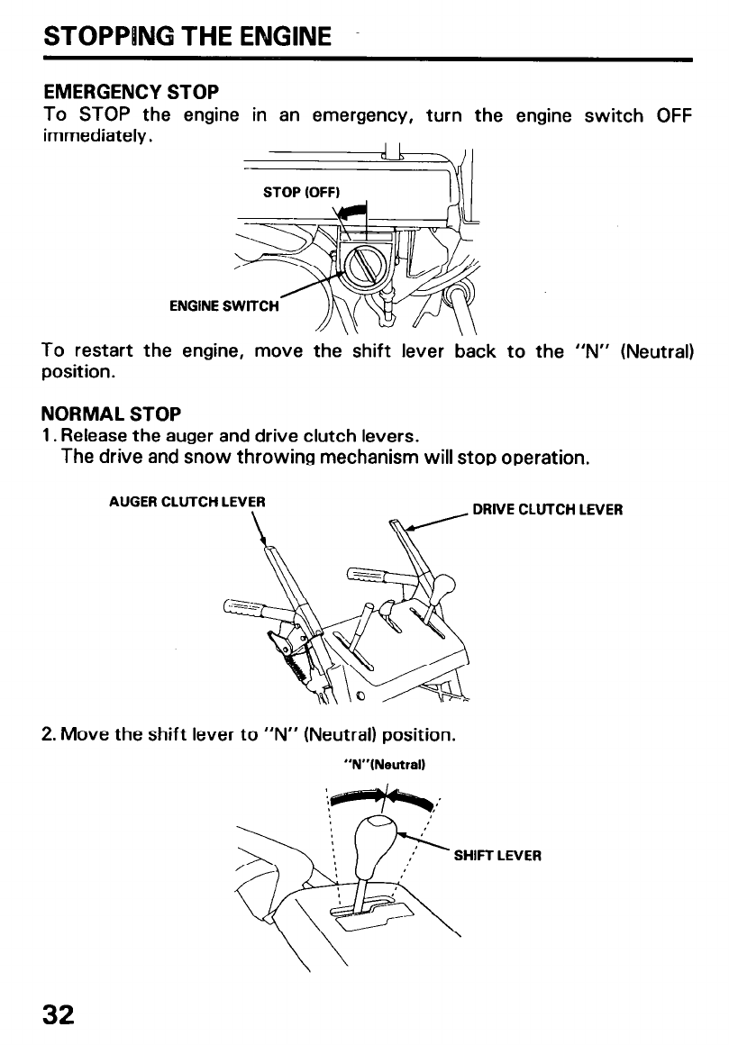
STOPPUNG THE ENGINE
EMERGENCY STOP
To STOP the engine in an emergency, turn the engine switch OFF
immediately.
ENGINE SWlTCH
To restart the engine, move the shift lever iack to the “N” (Neutral)
position.
NORMAL STOP
1. Release the auger and drive clutch levers.
The drive and snow throwing mechanism will stop operation.
AUGER CLUTCH LEVER DRNE CLUTCH LEVER
2. Move the shift lever to “N” (Neutral) position.
“N”(Neutral)
SHIFT LEVER
32
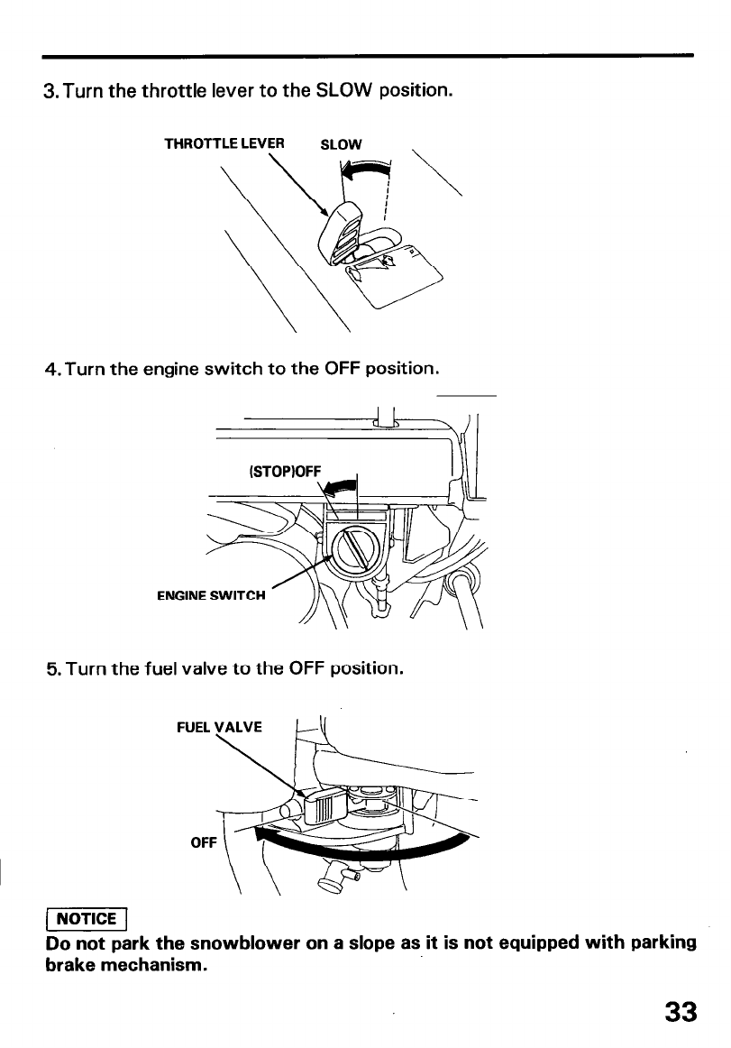
3.Turn the throttle lever to the SLOW position.
THROTTLE LEVER SLOW \
4. Turn the engine switch to the OFF position.
ENGINE SWITCH
5. Turn the fuel valve to the OFF position.
Do not park the snowblower on a slope as it is not equipped with parking
brake mechanism.
33
MAINTENANCE
Periodic inspection and maintenance will help extend the service life of
your snowblower while keeping it in the best operating condition. Inspect
or service as described on the table below.
l Shut off the engine before performing inspection and maintenance, and
disconnect the spark plug wire from the plug so that the engine cannot
be started.
l If the engine must run, make sure the area is wellventilated. Exhaust
gas contains poisonous carbon monoxide; exposure can cause loss of
consciousness and may lead to death.
l To avoid overturning, place the snowblower on a level surface before
performing inspection and maintenance.
l Use only genuine HONDA parts or their equivalent. Replacement parts
which are not of equivalent quality may damage the snowblower.
34
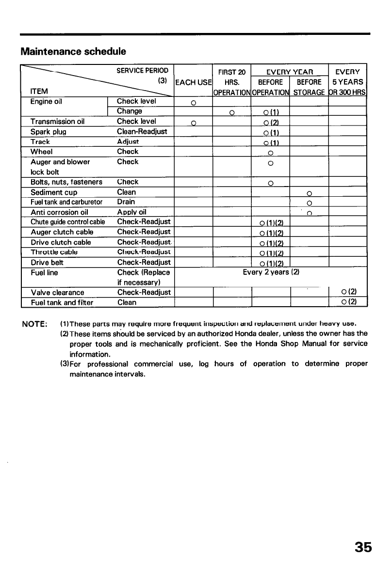
Maintenance schedule
if necessary)
Valve clearance Check-Readjust 1 oul
and filter Cban I I I I O(21
NOTE: (1)These parts may require more frequent inspection and replacement under heavy use.
UThese items should be serviced by an authorized Honda dealer, unless the owner has the
proper tools and is mechanically proficient. See the Honda Shop Manual for service
information.
(SjFor professional commercial use, log hours of operation to determine proper
maintenance intervals.
35
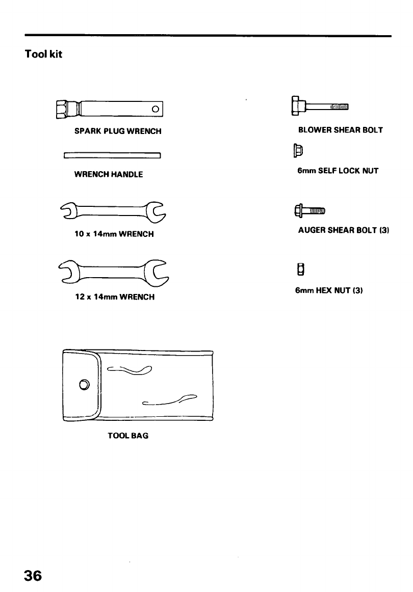
Tool kit
Ill 0
SPARK PLUG WRENCH
WRENCH HANDLE
10 x 14mm WRENCH
12 x 14mm WRENCH
BLOWER SHEAR BOLT
6mm SELF LOCK NUT
AUGER SHEAR BOLT (31
6mm HEX NUT (3)
TOOL BAG
36
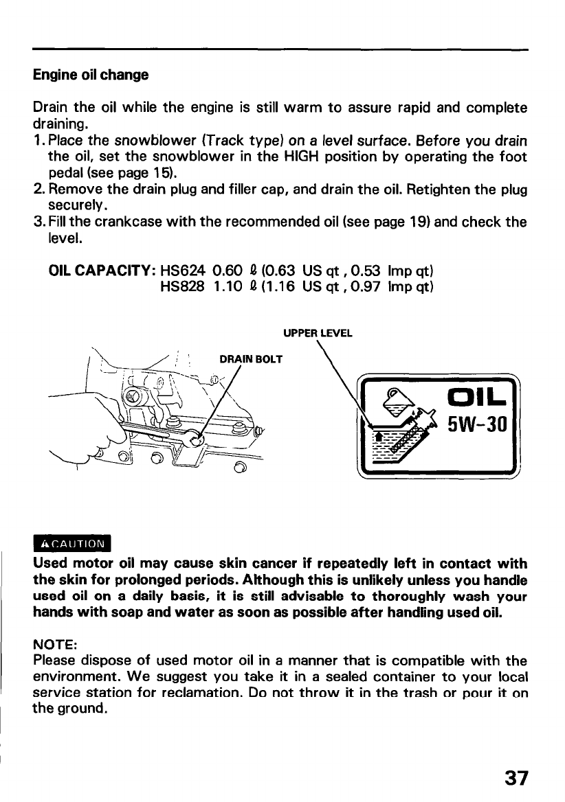
Engine oil change
Drain the oil while the engine is still warm to assure rapid and complete
draining.
1. Place the snowblower (Track type) on a level surface. Before you drain
the oil, set the snowblower in the HIGH position by operating the foot
pedal (see page 15).
2. Remove the drain plug and filler cap, and drain the oil. Retighten the plug
securely.
3. Fill the crankcase with the recommended oil (see page 19) and check the
level.
OIL CAPACITY: HS624 0.60 Q (0.63 US qt ,0.53 Imp qt)
HS828 1 .lO Q (1.16 US qt ,0.97 Imp qt)
UPPER LEVEL
\
Used motor oil may cause skin cancer if repeatedly left in contact with
the skin for prolonged periods. Although this is unlikely unless you handle
used oil on a daily basis, it is still advisable to thoroughly wash your
hands with soap and water as soon as possible after handling used oil.
NOTE:
Please dispose of used motor oil in a manner that is compatible with the
environment. We suggest you take it in a sealed container to your local
service station for reclamation. Do not throw it in the trash or pour it on
the ground.
37
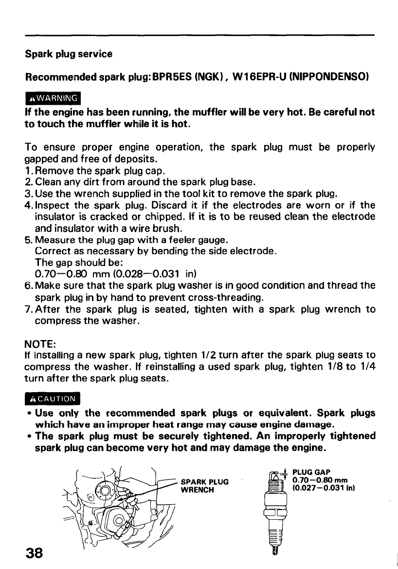
Spark plug service
Recommended spark plug: BPR5ES (NGK) , W 1 GEPR-U (NIPPONDENSO)
lf the engine has been running, the muffler will be very hot. Be careful not
to touch the muffler while it is hot.
To ensure proper engine operation, the spark plug must be properly
gapped and free of deposits.
1. Remove the spark plug cap.
2. Clean any dirt from around the spark plug base.
3. Use the wrench supplied in the tool kit to remove the spark plug.
4.lnspect the spark plug. Discard it if the electrodes are worn or if the
insulator is cracked or chipped. If it is to be reused clean the electrode
and insulator with a wire brush.
5. Measure the plug gap with a feeler gauge.
Correct as necessary by bending the side electrode.
The gap shoukl be:
0.70-0.80 mm (0.028-0.031 in)
6. Make sure that the spark plug washer is in good condition and thread the
spark plug in by hand to prevent cross-threading.
7.After the spark plug is seated, tighten with a spark plug wrench to
compress the washer.
NOTE:
lf installing a new spark plug, tighten l/2 turn after the spark plug seats to
compress the washer. If reinstalling a used spark plug, tighten l/8 to l/4
turn after the spark plug seats.
l Use only the recommended spark plugs or equivalent. Spark plugs
which have an improper heat range may cause engine damage.
l The spark plug must be securely tightened. An improperly tightened
spark plug can become very hot and may damage the engine.
SPARK PLUG
WRENCH
PLUG GAP
0.70-0.80 mm
(0.027-0.031 in)
38
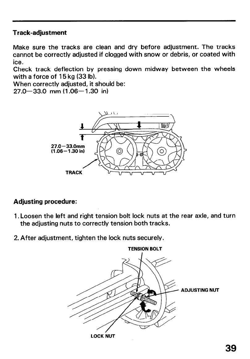
Track-adjustment
Make sure the tracks are clean and dry before adjustment. The tracks
cannot be correctly adjusted if clogged with snow or debris, or coated with
ice.
Check track deflection by pressing down midway between the wheels
with a force of 15 kg (33 lb).
When correctly adjusted, it should be:
27.0-33.0 mm (1.06-l .30 in)
27.0-
(1.06
Adjusting procedure:
1, Loosen the left and right tension bolt lock nuts at the rear axle, and turn
the adjusting nuts to correctly tension both tracks.
2. After adjustment, tighten the lock nuts securely.
TENSION BOLT
ADJUSTING NUT
LOCK NUT
39

Wheel/Tire Inspection
l Check side wall and tread surface of each tire for cracks, damage, or
excessive wear.
l Check the tire pressure
Tire pressure: 80- 100 kPa (0.8- f .O kg/cm* , 11.4- 14 psi)
40

Auger/Blower inspection
Check the auger, auger housing, blower and shear bolts for signs of
damage or other faults. If any of the shear bolts are broken, replace them
with the one furnished with the snowblower. Additional shear bolts and
nuts are available from authorized Honda snowblower dealers.
Shear bolts are designed to break under force that would otherwise
damage auger and blower parts. Do not replace shear bolts with ordinary
hardware bolts.
Shear bolt replacement procedure
1. Place the showblower on a firm, level surface.
2. Turn the engine switch OFF and remove the cap from the spark plug.
3. Clean the auger and blower of snow, ice or any other foreign particles.
4. Check the entire snow clearing mechanism.
5. Replace any broken shear bolts. Tighten securely.
BLOWER SHEAR BOLT 6mm SELF NUT
6mm HEX NUT (2) AUGER SHEAR BOLT (2)
41
TRANSPORTING
Before loading
1. Loading the snowblower on a trailer should be performed on a firm, level
surface.
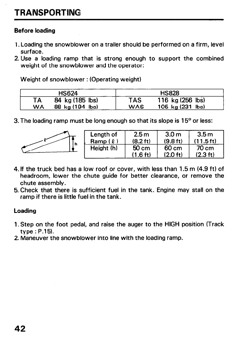
2. Use a loading ramp that is strong enough to support the combined
weight of the snowblower and the operator:
Weight of snowblower : (Operating weight)
HS624 HS828
TA 84 kg (185 Ibs) TAS 116 kg (256 Ibs)
WA 88 kg (194 Ibs) WAS 105 kg (231 Ibs)
3. The loading ramp must be long enough so that its slope is 15O or less:
4. If the truck bed has a low roof or cover, with less than 1.5 m (4.9 ft) of
headroom, lower the chute guide for better clearance, or remove the
chute assembly.
5. Check that there is sufficient fuel in the tank. Engine may stall on the
ramp if there is little fuel in the tank.
Loading
1. Step on the foot pedal, and raise the auger to the HIGH position (Track
type : P.15).
2. Maneuver the snowblower into line with the loading ramp.
42
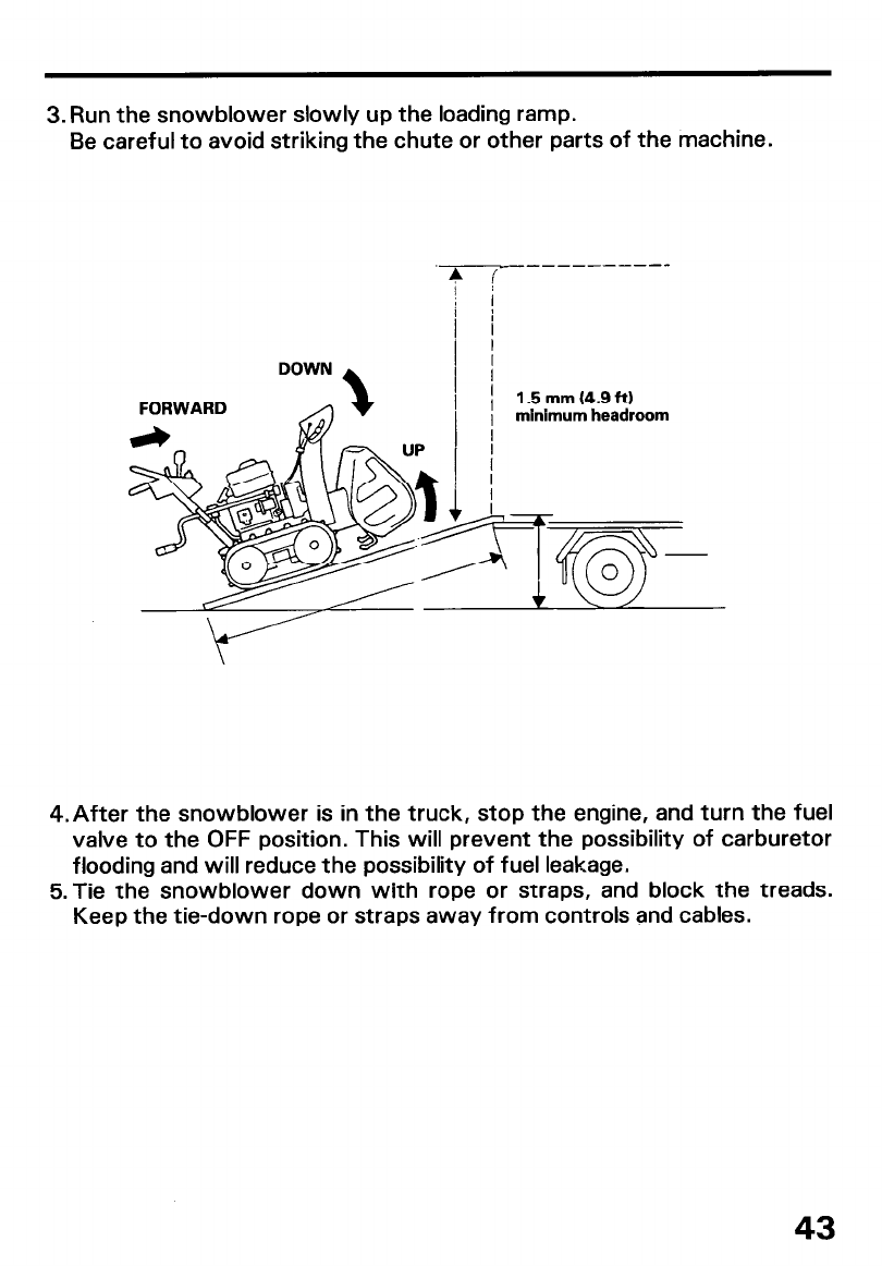
3. Run the snowblower slowly up the loading ramp.
Be careful to avoid striking the chute or other parts of the machine.
FORWARD 1.5 mm (4.9 ft)
minimum headroom
4.After the snowblower is in the truck, stop the engine, and turn the fuel
valve to the OFF position. This will prevent the possibility of carburetor
flooding and will reduce the possibility of fuel leakage.
5.Tie the snowblower down with rope or straps, and block the treads.
Keep the tie-down rope or straps away from controls and cables.
43
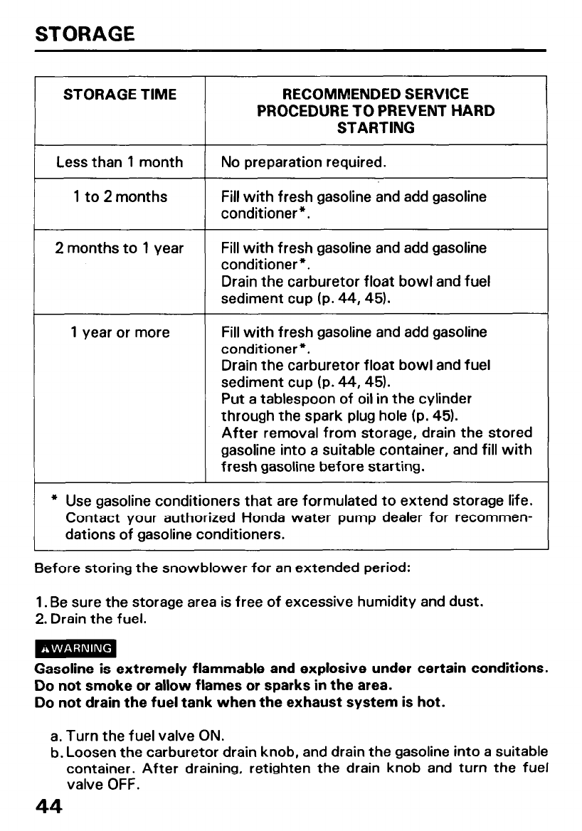
STORAGE
STORAGE TIME RECOMMENDED SERVICE
PROCEDURE TO PREVENT HARD
STARTING
Less than 1 month
1 to 2 months
No preparation required.
Fill with fresh gasoline and add gasoline
conditioner*.
2 months to 1 year Fill with fresh gasoline and add gasoline
conditioner*.
Drain the carburetor float bowl and fuel
sediment cup (p. 44,451.
1 year or more Fill with fresh gasoline and add gasoline
conditioner*.
Drain the carburetor float bowl and fuel
sediment cup (p. 44,451.
Put a tablespoon of oil in the cylinder
through the spark plug hole (p. 45).
After removal from storage, drain the stored
gasoline into a suitable container, and fill with
fresh gasoline before starting.
l Use gasoline conditioners that are formulated to extend storage life.
Contact your authorized Honda water pump dealer for recommen-
dations of gasoline conditioners.
Before storing the snowblower for an extended period:
1. Be sure the storage area is free of excessive humidity and dust.
2. Drain the fuel.
Gasoline is extremely flammable and explosive under certain conditions.
Do not smoke or allow flames or sparks in the area.
Do not drain the fuel tank when the exhaust system is hot.
a. Turn the fuel valve ON.
b. Loosen the carburetor drain knob, and drain the gasoline into a suitable
container. After draining, retighten the drain knob and turn the fuel
valve OFF.
44
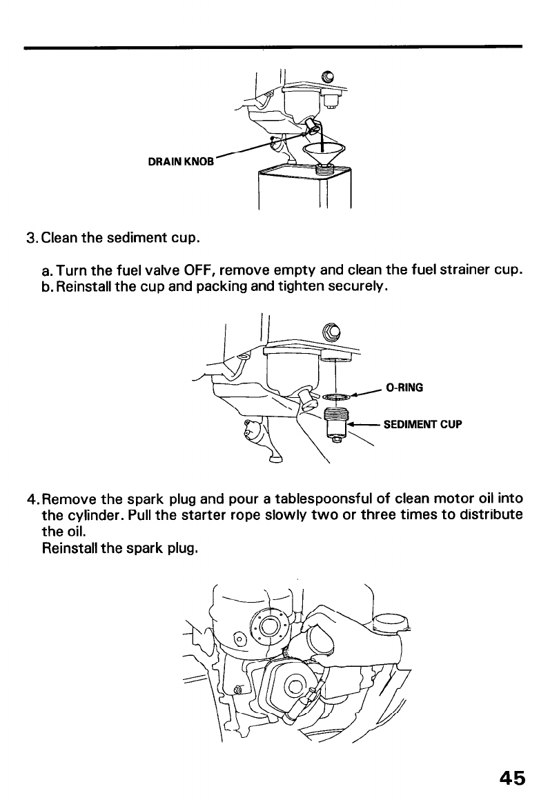
DRAIN KNOB
3. Clean the sediment cup.
a. Turn the fuel valve OFF, remove empty and clean the fuel strainer cup.
b. Reinstall the cup and packing and tighten securely.
O-RING
SEDIMENT CUP
4.Remove the spark plug and pour a tablespoonsful of clean motor oil into
the cylinder. Pull the starter rope slowly two or three times to distribute
the oil.
Reinstall the spark plug.
45

5. Pull the starter grip until resistance is felt. This closes the valves and
protects the engine from internal corrosion.
STARTER GRIP
6. Apply oil to the following parts for lubrication and rust prevention.
46
TROUBLESHOOTING
When the engine will not start:
1. Is there enough fuel?
2. Is the fuel valve on?
3. Is gasoline reaching the carburetor?
To check, loosen the drain screw with the fuel valve on. Fuel should flow
freely.
4. Is the throttle in the correct position?
Gasoline is extremely flammable, and gasoline vapor can explode.
If any fuel is spilled, make sure the area is dry before testing the spark
plug or starting the engine. Spilled fuel or fuel vapor may ignite.
5. Is the engine switch on?
6. Is there a spark at the spark plug?
a. Remove the spark plug cap. Clean any dirt from around the spark plug
base, then remove the spark plug.
b. Install the spark plug in the plug cap.
c. Turn the engine switch on.
d. Ground the side electrode at any engine gronud and crank the engine
to see if sparks jump across the gap.
l Never hold the spark plug lead with wet hands while performing this
test.
l Make sure that no fuel has been spilled on the engine and that the plug
is not wet with fuel.
l To avoid fire hazards, do not allow sparks near the plug hole.
e. If there are no sparks, replace the plug.
If sparks occur, try to start the engine according to the instructions.
7. If the engine still does not start, take the snowblower to an authorized
Honda dealer.
If the auger or blower does not operate, check the shear bolts (p. 41 1.
Replacement shear bolts and nuts were supplied with your snowblower.
Additional shear bolts and nuts are available from authorized Honda
snowblower dealers. Do not replace shear bolts with ordinary hardware
bolts.
47
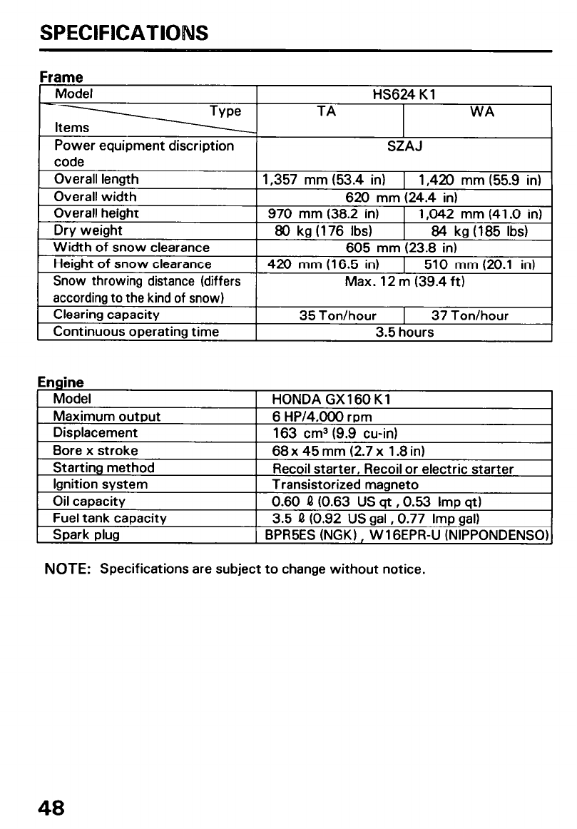
SPECIFICATIONS
Frame
Model
Power equipment discription
code
l-IS624 K 1
TA WA
SZAJ
Overall length 1,357 mm (53.4 in) 1 1,420 mm (55.9 in)
Overall width 620 mm (24.4 in)
Overall height 970 mm (38.2 in) 1 1,042 mm (41 .O in)
Dry weight 80 kg (176 Ibs) 84 kg (185 Ibs)
Width of snow clearance 605 mm (23.8 in)
Height of snow clearance 420 mm (16.5 in) 1 510 mm (20.1 in)
Snow throwing distance (differs Max. 12 m (39.4 ft)
according to the kind of snow)
Clearing capacity 35 Ton/hour 37 Ton/hour
Continuous operating time 3.5 hours
Engine
Model
Maximum output
Displacement
Bore x stroke
Starting method
Ignition system
Oil capacity
Fuel tank capacity
Spark plug
HONDA GX 160 K 1
6 HP/4,000 rpm
163 cm3 (9.9 cu-in)
68 x 45 mm (2.7 x 1.8 in)
Recoil starter, Recoil or electric starter
Transistorized magneto
0.60 Q (0.63 US qt ,0.53 Imp qt)
3.5 Q (0.92 US gal ,0.77 Imp gal)
BPR5ES (NGK) , W 1 GEPR-U (NIPPONDENSO)
NOTE: Specifications are subject to change without notice.
48
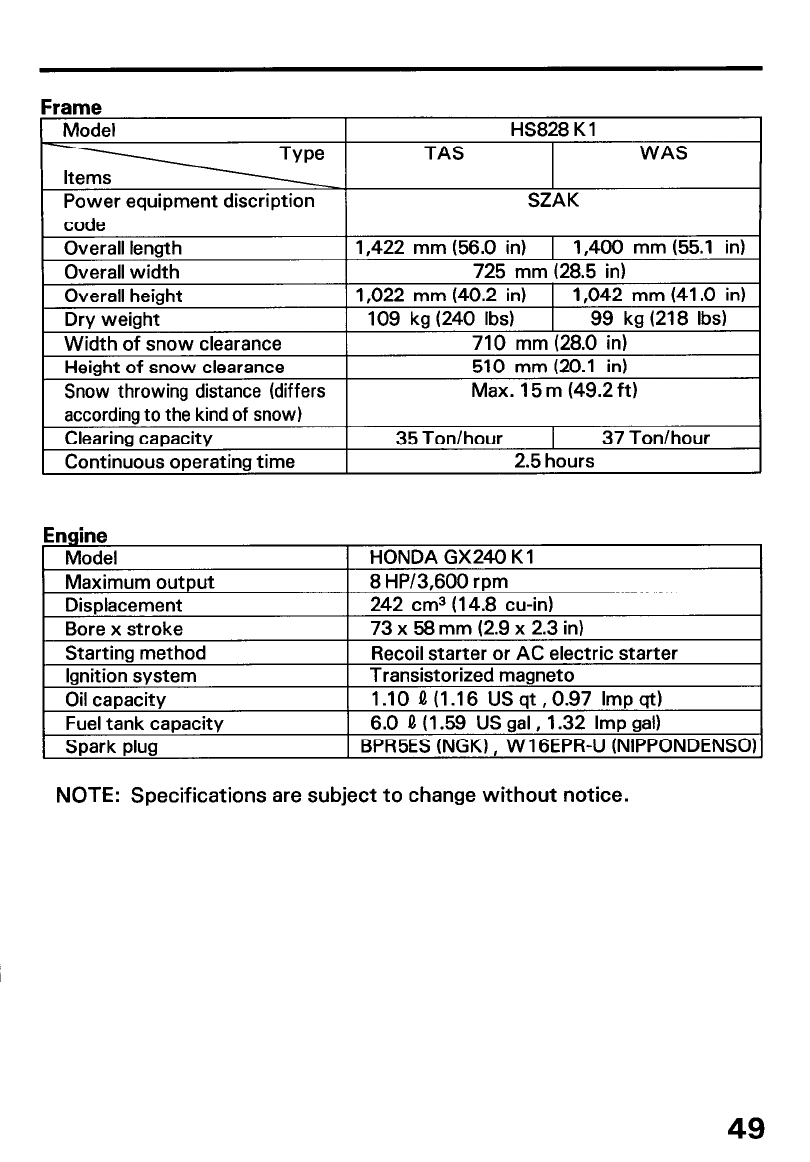
FI rame
Model
Power equipment discription
HS828 K 1
TAS WAS
SZAK
code I
Overall lenath
Overall width
Overall height
Width oi snow clearance
I 1.422 mn
Drv weight
n (56.0 in) 1 1,400 mm (55.1 in)
725 mm (28.5 in)
1,022 mm (40.2 in) 1 1,042 mm (41 .O in)
: 39 kg (240 Ibs) 99 kg (218 Ibs)
710 mm (28.0 in)
I I(
Height of snow clearance
Snow throwing distance (differs 1
510 mm (20.1 in
1
Max. 15 m (49.2 f ‘t)
according to the kind of snow)
Clearing capacity
Continuous operating time
35 Ton/hour 37 Ton/hour
2.5 hours
Engine
Model
Maximum output
Displacement
Bore x stroke
Starting method
Ignition system
Oil capacity
Fuel tank capacity
Spark plug
HONDA GX240 Kl
8 HP/3,600 rpm
242 cm3 (14.8 cu-in)
73 x 58 mm (2.9 x 2.3 in)
Recoil starter or AC electric starter
Transistorized magneto
1 .lO fl (I .I 6 US qt ,0.97 Imp qt)
6.0 0 (1.59 US gal, 1.32 Imp gal)
BPR5ES (NGK) , W 1 GEPR-U (NIPPONDENS
NOTE: Specifications are subject to change without notice.
49
CUSTOMER SERVOCE INFORMATION
Honda power equipment dealership personnel are trained professionals.
They should be able to answer any question you may have. If you
encounter a problem that your dealer does not solve to your satisfaction,
please discuss it with the dealership’s management. The Service Manager
or General Manager can halp. Almost all problems are solved in this way.
lf you are dissatisfied with the decision made by the dealership’s
management, contact the Honda Power Equipment Customer Service
Office. You can write to:
American Honda Motor Co., Inc.
Honda Power Equipment Division
Customer Service Office
4475 River Green Parkway
Duluth, Georgia 30136-9420
Or telephone: (4041497-6400
When you write or call, please give us this information:
l Model and serial number
l Name of dealer who sold the snowblower to you
l Name and address of dealer who services your snowblower
l Date of purchase
l Your name, address, and telephone number
l A detailed description of the problem
50
INDEX
COMPONENT IDENTIFICATION .........................................................................
CONTROLS ..........................................................................................................
Chute crank ................................................................................................... IO
Chute guide .................................................................................................... I2
Drive clutch lever and clutch lever .............................................................. 13
Engine switch ................................................................................................... 9
Foot pedal ....................................................................................................... I5
Fuel valve.. ....................................................................................................... .9
Fuel gauge.. ..................................................................................................... IO
Shift lever ....................................................................................................... 12
Skid plate, Scraper ........................................................................................ I4
Starter grip ..................................................................................................... 11
Throttle lever(Engine speed) ........................................................................ I 1
Transmission release lever .......................................................................... .I6
CUSTOMER SERVICE INFORMATION .......................................................... .50
MAINTENACE .................................................................................................... 34
Auger/Blower inspection.. ........................................................................... .41
Engine oil change .......................................................................................... .37
Maintenance schedule ................................................................................. .35
Spark plug service ......................................................................................... 38
Tool kit.. ......................................................................................................... .36
Track-Adjustment ........................................................................................ .39
PRE-OPERATION CHECK ................................................................................. 17
Auger and blower bolts ................................................................................. 21
Engine oil ......................................................................................................... I9
Fuel recommendation .................................................................................. .I 7
Hydrostatic transmission fluid ..................................................................... 20
Other checks .................................................................................................. 21
SNOW BLOWER OPERATION .......................................................................... 27
Clearing snow ................................................................................................ 30
SPECIFICATIONS ............................................................................................. .48
STARTING THE ENGINE .................................................................................. .22
STOPPING THE ENGINE ................................................................................... 32
STORAGE ......................................................................................................... .44
TRANSPORTING ............................................................................................... 42
Before loading ................................................................................................ 42
Loading .......................................................................................................... .42
TROUBLESHOOTING.. .................................................................................... ..4 7
51

Printed on
Recycled Paper
POM53437
IKON 100.2001.11
PRINTED IN U.S.A.
P/N 31767700
00X31-767-7000
K1
