Honeywell Analytics 301W-1 Wireless Gas Sensor User Manual 301W E
Honeywell Analytics Wireless Gas Sensor 301W E
UserManual.wiki
>
Honeywell Analytics
>
301W 1 User Manual
UserMan
Navigation menu
Upload a User Manual
Namespaces
Wiki Guide
HTML
PDF
Info
Views
User Manual
Discussion / Help
Navigation


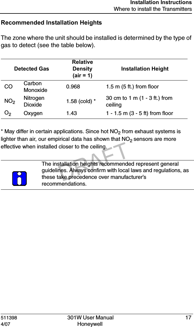
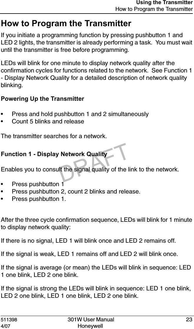
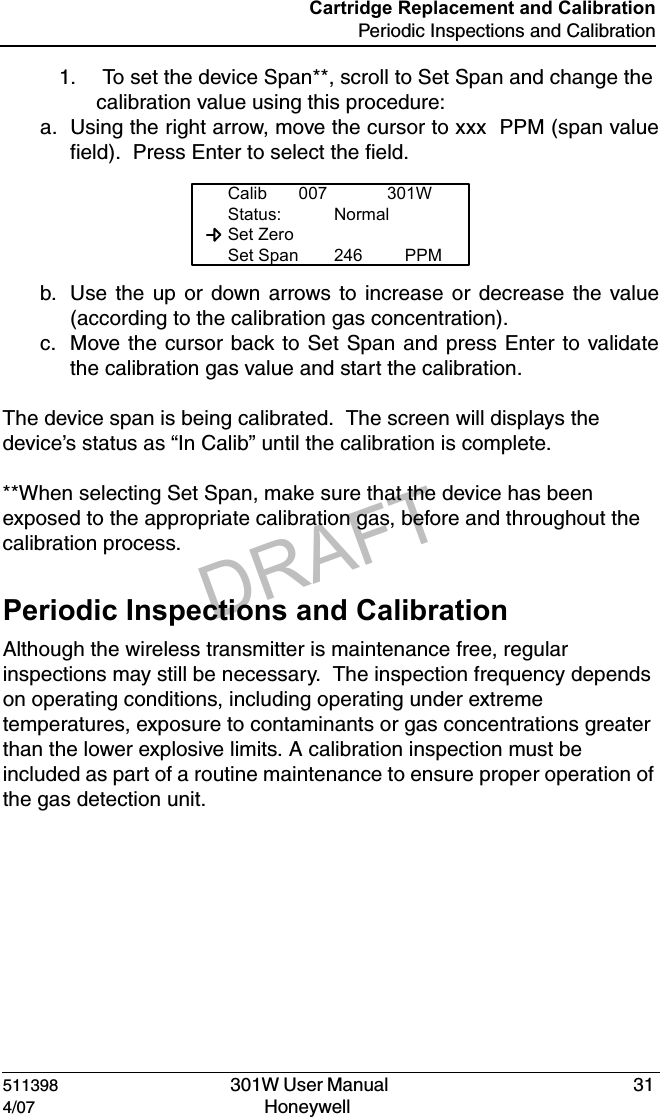
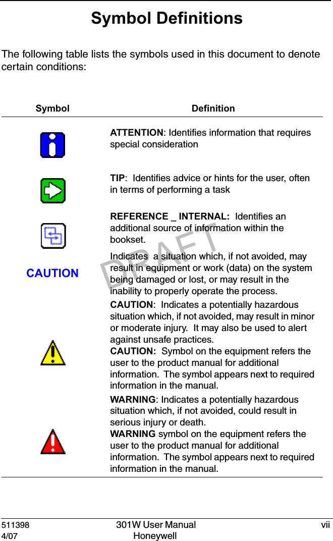
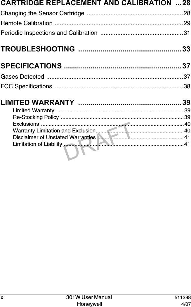
![DRAFT511398 301W User Manual v4/07 Honeywell ContactsWorld Wide WebThe following Honeywell Websites may be of interest to our customers:TelephoneContact us by telephone at the numbers listed below:Sales InformationsContact us at sales@vulcaininc.comHoneywell Organization WWW Address (URL)Corporate http:/www.honeywellanalytics.comLife Sciences http:/www.honeywell.comInternational http:/content.honeywell.com/global/ Organization Phone NumberUnited Statesand CanadaHoneywell Analytics International Inc.1-800-563-29671-450-619-2450Fax: 1-450-619-2448Asia Pacific Honeywell Asia Pacific Inc.Hong Kong (852) 23 31 9133Europe Honeywell PaceBrussels, Belgium [32-2]728-2711Latin America Honeywell International Inc.Sunrise, Florida, U.S.A. (954) 845-2600](https://usermanual.wiki/Honeywell-Analytics/301W-1/User-Guide-789470-Page-5.png)


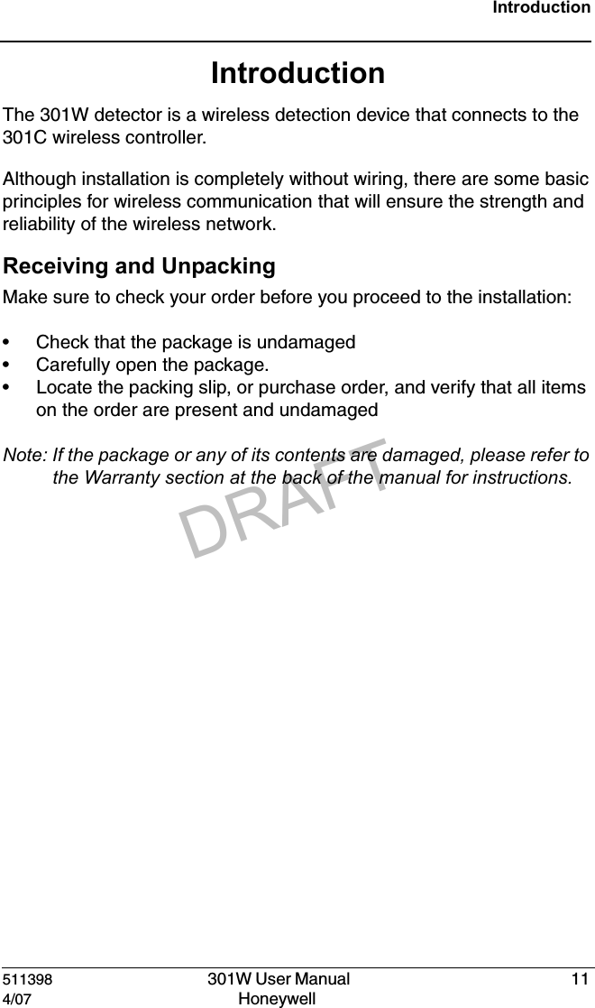
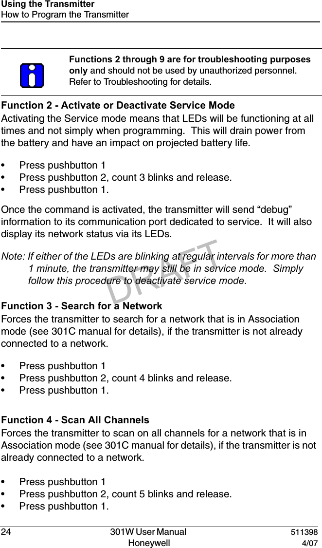
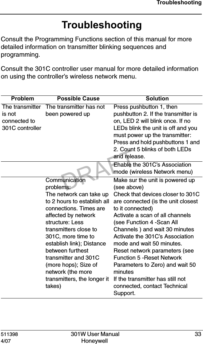
![DRAFT511398 301W User Manual 124/07 Honeywell Installation InstructionsBasic GuidelinesInstallation InstructionsBasic GuidelinesFollow these instructions to the letter to ensure that the equipment will function properly. Failure to respect these guidelines will release Honeywell Analytics from any responsibility in the event of improper functioning:• Make sure to locate all transmitters in areas easily accessible for service.• Avoid locations where instruments are subject to vibrations• Avoid locating transmitters near sources of electromagnetic interference• Avoid locating transmitters in areas subject to significant temperature swings• Transmitters should be installed 1.5 m (5 ft.) above the floor for CO transmitters to prevent signal interference by vehicles ( NO2 transmitters should be installed 30 cm [1 ft] from the ceiling.) • Install transmitters in upright position (to ensure ease of use and access to programming pushbuttons).• Place transmitters so that they are facing the center of the area• Do not install a transmitter facing a parking space; the vehicle will sever the communication link. If possible, install the transmitter perpendicular to the space.• Avoid installing the transmitters on or near metal (transformers, pipes, etc.)• Do not install transmitters on ceilings• Do not install transmitters in ceiling or wall wells (placement in these areas may impede signal transmission)](https://usermanual.wiki/Honeywell-Analytics/301W-1/User-Guide-789470-Page-12.png)