Honeywell Analytics 301W-1 Wireless Gas Sensor User Manual 301W E
Honeywell Analytics Wireless Gas Sensor 301W E
UserMan

DRAFT
Wireless Gas Monitoring Device
301W
Installation and User Manual
ERP 511398
4/07
DRAFT

DRAFT
511398 301W User Manual iii
4/07 Honeywell
Notices and Trademarks
Copyright by Honeywell International Inc.
Release 511398 April 2007
While this information is presented in good faith and believed to be accurate,
Honeywell disclaims the implied warranties of merchantability for a particular
purpose and makes no express warranties except as may be stated in its
written agreement with and for its customers.
In no event is Honeywell liable to anyone for any indirect, special or
consequential damages. The information and specifications in this document
are subject to change without notice.
Honeywell Analytics
4005 Matte Blvd, Unit G
Brossard, Quebec, J4Y 2P4
DRAFT

DRAFT
511398 301W User Manual v
4/07 Honeywell
Contacts
World Wide Web
The following Honeywell Websites may be of interest to our customers:
Telephone
Contact us by telephone at the numbers listed below:
Sales Informations
Contact us at sales@vulcaininc.com
Honeywell Organization WWW Address (URL)
Corporate http:/www.honeywellanalytics.com
Life Sciences http:/www.honeywell.com
International http:/content.honeywell.com/global/
Organization Phone Number
United States
and Canada
Honeywell Analytics
International Inc.
1-800-563-2967
1-450-619-2450
Fax: 1-450-619-2448
Asia Pacific Honeywell Asia Pacific Inc.
Hong Kong (852) 23 31 9133
Europe Honeywell Pace
Brussels, Belgium [32-2]728-2711
Latin America Honeywell International Inc.
Sunrise, Florida, U.S.A. (954) 845-2600
DRAFT
DRAFT
511398 301W User Manual vii
4/07 Honeywell
Symbol Definitions
The following table lists the symbols used in this document to denote
certain conditions:
Symbol Definition
ATTENTION: Identifies information that requires
special consideration
TIP: Identifies advice or hints for the user, often
in terms of performing a task
REFERENCE _ INTERNAL: Identifies an
additional source of information within the
bookset.
CAUTION
Indicates a situation which, if not avoided, may
result in equipment or work (data) on the system
being damaged or lost, or may result in the
inability to properly operate the process.
CAUTION: Indicates a potentially hazardous
situation which, if not avoided, may result in minor
or moderate injury. It may also be used to alert
against unsafe practices.
CAUTION: Symbol on the equipment refers the
user to the product manual for additional
information. The symbol appears next to required
information in the manual.
WARNING: Indicates a potentially hazardous
situation which, if not avoided, could result in
serious injury or death.
WARNING symbol on the equipment refers the
user to the product manual for additional
information. The symbol appears next to required
information in the manual.
DRAFT

DRAFT
511398 301W User Manual ix
4/07 Honeywell
Contents
INTRODUCTION ............................................................11
Receiving and Unpacking ...................................................................... 11
INSTALLATION INSTRUCTIONS ..................................12
Basic Guidelines ................................................................................ 12
Network Requirements ...................................................................... 13
Determining the Number of Transmitters .............................................. 13
Where to install the Transmitters ....................................................... 15
Installing the Transmitters ..................................................................... 16
Recommended Installation Heights ........................................ 17
System Startup .................................................................................. 18
Programming interface .......................................................................... 19
USING THE TRANSMITTER ..........................................21
Programming Functions .................................................................... 22
How to Program the Transmitter ....................................................... 23
Powering Up the Transmitter .................................................. 23
Function 1 - Display Network Quality ..................................... 23
Function 2 - Activate or Deactivate Service Mode ................. 24
Function 3 - Search for a Network .......................................... 24
Function 4 - Scan All Channels .............................................. 24
Function 5 - Reset Network Parameters to Zero .................... 25
Function 7 - Adjust Sensor Zero ............................................. 26
Function 8 - Adjust Span ........................................................ 26
Function 9 - Save Parameters and Close Device .................. 27
Cancelling all commands ....................................................... 27

DRAFT
x 301W User Manual 511398
Honeywell 4/07
CARTRIDGE REPLACEMENT AND CALIBRATION ...28
Changing the Sensor Cartridge .........................................................28
Remote Calibration ............................................................................29
Periodic Inspections and Calibration .................................................31
TROUBLESHOOTING ...................................................33
SPECIFICATIONS .......................................................... 37
Gases Detected .................................................................................37
FCC Specifications ............................................................................38
LIMITED WARRANTY ...................................................39
Limited Warranty ....................................................................................39
Re-Stocking Policy .................................................................................39
Exclusions ..............................................................................................40
Warranty Limitation and Exclusion......................................................... 40
Disclaimer of Unstated Warranties ........................................................41
Limitation of Liability ...............................................................................41

DRAFT
511398 301W User Manual 11
4/07 Honeywell
Introduction
Introduction
The 301W detector is a wireless detection device that connects to the
301C wireless controller.
Although installation is completely without wiring, there are some basic
principles for wireless communication that will ensure the strength and
reliability of the wireless network.
Receiving and Unpacking
Make sure to check your order before you proceed to the installation:
• Check that the package is undamaged
• Carefully open the package.
• Locate the packing slip, or purchase order, and verify that all items
on the order are present and undamaged
Note: If the package or any of its contents are damaged, please refer to
the Warranty section at the back of the manual for instructions.

DRAFT
511398 301W User Manual 12
4/07 Honeywell
Installation Instructions
Basic Guidelines
Installation Instructions
Basic Guidelines
Follow these instructions to the letter to ensure that the equipment will
function properly. Failure to respect these guidelines will release
Honeywell Analytics from any responsibility in the event of improper
functioning:
• Make sure to locate all transmitters in areas easily accessible for
service.
• Avoid locations where instruments are subject to vibrations
• Avoid locating transmitters near sources of electromagnetic
interference
• Avoid locating transmitters in areas subject to significant
temperature swings
• Transmitters should be installed 1.5 m (5 ft.) above the floor for CO
transmitters to prevent signal interference by vehicles ( NO2
transmitters should be installed 30 cm [1 ft] from the ceiling.)
• Install transmitters in upright position (to ensure ease of use and
access to programming pushbuttons).
• Place transmitters so that they are facing the center of the area
• Do not install a transmitter facing a parking space; the vehicle will
sever the communication link. If possible, install the transmitter
perpendicular to the space.
• Avoid installing the transmitters on or near metal (transformers,
pipes, etc.)
• Do not install transmitters on ceilings
• Do not install transmitters in ceiling or wall wells (placement in
these areas may impede signal transmission)

DRAFT
511398 301W User Manual 13
4/07 Honeywell
Installation Instructions
Network Requirements
Network Requirements
Certain criteria may affect the number of transmitters required for a
network. The following points have an impact on installation:
• The type of area covered; whether it is an open garage, wall type
(full or half concrete, gypsum, etc.) and ceiling height.
• Area to cover; maximum distance between transmitters is 30.5 m
(100 ft) therefore, the greater the area, the more transmitters are
needed.
• Depending on the distribution and layout of your network, more
than one 301C controller may be required.
• If the controller (or relay module) is installed in a closed area, away
from the central transmitter area, two additional transmitters are
required outside of the enclosed area to act as signal relays.
Determining the Number of Transmitters
The number of transmitters required is determined by a unit’s
communication radius, the area where it will be installed and by the
degree of protection desired (an increased number of units offers
increased security).
Sensor Surveillance Area
Gas Detected Monitoring
Radius Area Covered
CO Carbon
monoxide 15.24 m (50 ft.) 729 sq m (7,854 sq. ft.)
NO2Nitrogen dioxide 15.24 m (50 ft.) 729 sq m (7,854 sq. ft.)
O2Oxygen 7 m (23 ft.) 116.8 sq. m (1257 sq. ft)
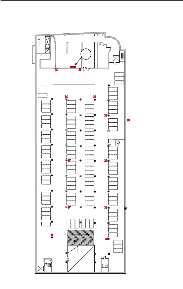
Honeywell Analytics recommends installing additional
transmitters near the ceiling (at ramp entrance points)
that act as transmission links when communication is
weak.
DRAFT
14 301W User Manual 511398
Honeywell 4/07
Installation Instructions
Network Requirements
Transmitter Locations
Example of transmitter placement.
Transmetteur
301W
Transmitter
Loading Zone
Zone de déchargement
Parking compound, lower level
Stationnement, niveau inférieur
301C
DRAFT
511398 301W User Manual 15
4/07 Honeywell
Installation Instructions
Where to install the Transmitters
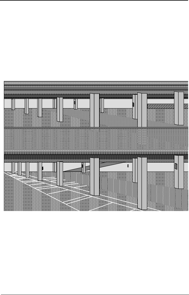
Where to install the Transmitters
The 301W wireless transmitters use wireless communication that has a
maximum range of 30.5 meters (100 ft), therefore transmitters should
never be more than 30.5 meters apart.
Install transmitters on columns or surfaces facing the centre of the
parking garage (as shown). Do not install transmitters facing outer
walls.
Example of correct installation
P1
P2
A
C1 D1 F1
F2
C2
AC1 D1 F1
F2
C2
DRAFT
16 301W User Manual 511398
Honeywell 4/07
Installation Instructions
Where to install the Transmitters
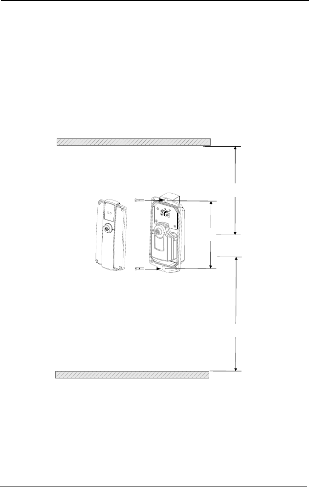
Installing the Transmitters
Since the unit is factory programmed, calibrated and completely
wireless, installation simply requires the physical mounting of the
enclosure.
Once you have selected locations for all the transmitters of your
network, temporarily affix them to their assigned places until you are
certain that their placement is appropriate and that transmitters and
communication are functioning. You can then permanently install the
units. Remove the cover on the 301W (to access the mounting holes).
Mark the holes, as shown:
• Height markers 22.5cm (8.85”) apart
• Pre-drill mounting holes as needed
• Securely mount the 301W using the appropriate screws
• Replace the unit’s cover
22.5 cm
8.85"
CO
1.5m (5')
Ground / sol
NO2
30 cm (12")
Ceiling/Plafond

DRAFT
511398 301W User Manual 17
4/07 Honeywell
Installation Instructions
Where to install the Transmitters
Recommended Installation Heights
The zone where the unit should be installed is determined by the type of
gas to detect (see the table below).
* May differ in certain applications. Since hot NO2 from exhaust systems is
lighter than air, our empirical data has shown that NO2 sensors are more
effective when installed closer to the ceiling.
Detected Gas
Relative
Density
(air = 1)
Installation Height
CO Carbon
Monoxide 0.968 1.5 m (5 ft.) from floor
NO2Nitrogen
Dioxide 1.58 (cold) * 30 cm to 1 m (1 - 3 ft.) from
ceiling
O2Oxygen 1.43 1 - 1.5 m (3 - 5 ft) from floor
The installation heights recommended represent general
guidelines. Always confirm with local laws and regulations, as
these take precedence over manufacturer’s
recommendations.

DRAFT
18 301W User Manual 511398
Honeywell 4/07
Installation Instructions
System Startup
System Startup
Once all the transmitters are mounted into position, there is a precise
order to follow when powering up the system.
1. Power up the 301C wireless controller and allow it to initialize
before powering up any of the transmitters.
2. Power up the transmitters one at a time, beginning with the
transmitter closest to the controller and working out to the farthest.
a.To power-up the transmitter press pushbuttons 1 and 2
simultaneously (located below the left and right LEDs,
respectively) and count 5 blinks of both LEDs, then release to
power up the transmitter. (LED 1 will blink while the transmitter
searches for a network.)
3. After all of the transmitters are powered up, you will need to wait
approximately 30 minutes to connect to the network.
Note: Depending on the number of transmitters and the distance
between transmitter and controller, it can take as long as 12
hours after initial startup to optimize the network.
The network should now be communicating and functional. If there are
any problems with the transmitters, the Troubleshooting section
provides some solutions to common problems.
DRAFT
511398 301W User Manual 19
4/07 Honeywell
Installation Instructions
System Startup
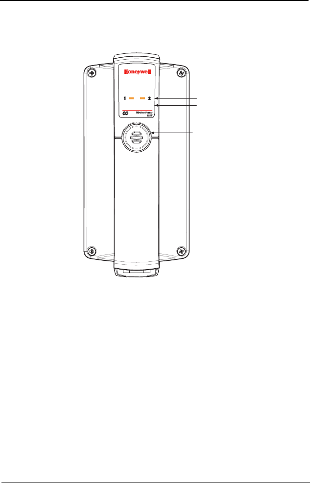
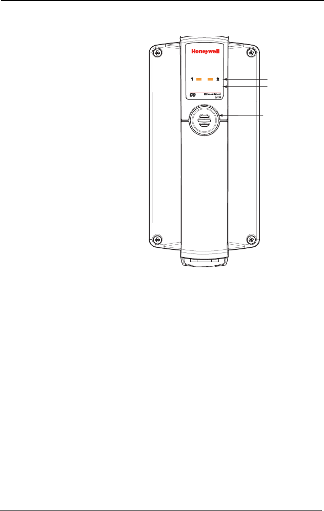
Programming interface
,%$SååANDå
0USHBUTTONSå
åANDååHIDDEN
3AMPLING#ALIBRATIONå
PORT
DRAFT

DRAFT
511398 301W User Manual 21
4/07 Honeywell
Using the Transmitter
Using the Transmitter
The 301W transmitter is designed to be plug-and-play; the product is
shipped with all settings factory pre-programmed (see Specifications
section for details). Nonetheless, certain settings can be modified
either through the 301C controller menus or through the transmitter
programming functions.
The programming functions on the transmitter should only be used by
qualified personnel. Whenever possible, it is prefereable to perform
programming functions using the 301C wireless controller menus.
Since programming interface is LED based, and LED
functions use battery power, all programming performed
directly on the transmitter will have an impact on battery life.
DRAFT
22 301W User Manual 511398
Honeywell 4/07
Using the Transmitter
Programming Functions
Programming Functions
There are several numbered
functions (pushbutton
sequences) that can be
performed directly on the
transmitter. Pushbuttons are
located in the area directly
below the LEDs; Pushbutton
1 is located below LED 1,
pushbutton 2 is located below
LED 2. This section provides
instructions on how to
perform each of these
functions.
Pushbutton 1 is used as the
access and Enter (or
confirmation) button, while
pushbutton 2 is used to select
commands. When selecting
a command function, you
must hold pushbutton 2 and
count the blinks (one for pushbutton activation and the number of times
representing the function number: For function 2, you must count 3
blinks; function 3, count 4 blinks, etc).
After each command selection, the LEDs will blink the command
number for 3 cycles to confirm the command (and give you the
opportunity to cancel). After the 3 cycles, the unit will execute the
command.
Example: You have selected command 7 (adjust sensor zero): LED 1
will blink 7 times, three times before executing the command.
You can cancel the command at any point before the end of
the third cycle (see Cancelling All Commands).
,%$SååANDå
0USHBUTTONSå
åANDååHIDDEN
3AMPLING#ALIBRATIONå
PORT

DRAFT
511398 301W User Manual 23
4/07 Honeywell
Using the Transmitter
How to Program the Transmitter
How to Program the Transmitter
If you initiate a programming function by pressing pushbutton 1 and
LED 2 lights, the transmitter is already performing a task. You must wait
until the transmitter is free before programming.
LEDs will blink for one minute to display network quality after the
confirmation cycles for functions related to the network. See Function 1
- Display Network Quality for a detailed description of network quality
blinking.
Powering Up the Transmitter
• Press and hold pushbutton 1 and 2 simultaneously
• Count 5 blinks and release
The transmitter searches for a network.
Function 1 - Display Network Quality
Enables you to consult the signal quality of the link to the network.
• Press pushbutton 1
• Press pushbutton 2, count 2 blinks and release.
• Press pushbutton 1.
After the three cycle confirmation sequence, LEDs will blink for 1 minute
to display network quality:
If there is no signal, LED 1 will blink once and LED 2 remains off.
If the signal is weak, LED 1 remains off and LED 2 will blink once.
If the signal is average (or mean) the LEDs will blink in sequence: LED
1 one blink, LED 2 one blink.
If the signal is strong the LEDs will blink in sequence: LED 1 one blink,
LED 2 one blink, LED 1 one blink, LED 2 one blink.

DRAFT
24 301W User Manual 511398
Honeywell 4/07
Using the Transmitter
How to Program the Transmitter
Function 2 - Activate or Deactivate Service Mode
Activating the Service mode means that LEDs will be functioning at all
times and not simply when programming. This will drain power from
the battery and have an impact on projected battery life.
• Press pushbutton 1
• Press pushbutton 2, count 3 blinks and release.
• Press pushbutton 1.
Once the command is activated, the transmitter will send “debug”
information to its communication port dedicated to service. It will also
display its network status via its LEDs.
Note: If either of the LEDs are blinking at regular intervals for more than
1 minute, the transmitter may still be in service mode. Simply
follow this procedure to deactivate service mode.
Function 3 - Search for a Network
Forces the transmitter to search for a network that is in Association
mode (see 301C manual for details), if the transmitter is not already
connected to a network.
• Press pushbutton 1
• Press pushbutton 2, count 4 blinks and release.
• Press pushbutton 1.
Function 4 - Scan All Channels
Forces the transmitter to scan on all channels for a network that is in
Association mode (see 301C manual for details), if the transmitter is not
already connected to a network.
• Press pushbutton 1
• Press pushbutton 2, count 5 blinks and release.
• Press pushbutton 1.
Functions 2 through 9 are for troubleshooting purposes
only and should not be used by unauthorized personnel.
Refer to Troubleshooting for details.

DRAFT
511398 301W User Manual 25
4/07 Honeywell
Using the Transmitter
How to Program the Transmitter
Function 5 - Reset Network Parameters to Zero
This function, which should only be used by authorized, fully
qualified technicians, resets the transmitter’s network parameters to
zero, enabling the transmitter to look for a new controller in Association
mode (see 301C manual for details).
• Press pushbutton 1
• Press pushbutton 2, count 6 blinks and release.
• Press pushbutton 1.
Function 6 - Activate a Check Test
This test essentially sends a neutral command that causes the
transmitter to react, thus enabling you to tell whether it is still
functioning.
• Press pushbutton 1
• Press pushbutton 2, count 7 blinks and release.
• Press pushbutton 1.
Once this function has been executed, the LEDs will display the result:
Success: Both LEDs blink simultaneously 6 times, for three cycles.
Failure: LED 1 blinks 6 times, for 3 cycles while LED 2 blinks non-
stop throughout the cycles.
This function resets the transmitter; once reset, transmitters
may change IDs, and thus render controller Events and
Groups inoperable.

DRAFT
26 301W User Manual 511398
Honeywell 4/07
Using the Transmitter
How to Program the Transmitter
The 301W sensors are designed to be maintenance free and do not
require calibration. The following calibration procedures (Functions 7
and 8) are provided as an exceptional troubleshooting measure.
Function 7 - Adjust Sensor Zero
• Press pushbutton 1
• Press pushbutton 2, count 8 blinks and release.
• Begin emitting the calibration gas
• Press pushbutton 1.
Note: Never calibrate any unit’s Zero with ambiant air. Always use
Nitrogen (N2) at the calibration port to calibrate the Zero.
Once this function has been executed, the LEDs will display the result:
Success: Both LEDs blink simultaneously 7 times, for three cycles.
Failure: LED 1 blinks 7 times, for 3 cycles while LED 2 blinks non-
stop throughout the cycles.
Function 8 - Adjust Span
Allows you to calibrate the sensor’s span. Remember to begin emitting
the calibration gas before starting the calibration.
• Press pushbutton 1
• Press pushbutton 2, count 9 blinks and release.
• Press pushbutton 1.
Once this function has been executed, the LEDs will display the result:
Success: Both LEDs blink simultaneously 8 times, for three cycles.
Failure: LED 1 blinks 8 times, for 3 cycles while LED 2 blinks non-
stop throughout the cycles.

DRAFT
511398 301W User Manual 27
4/07 Honeywell
Using the Transmitter
How to Program the Transmitter
Function 9 - Save Parameters and Close Device
Sends a shutdown command to the transmitter, which will save all
parameters and power down.
• Press pushbutton 1
• Press pushbutton 2, count 10 blinks and release.
• Press pushbutton 1.
Both LEDs will remain on while the transmitter saves its parameters.
When the LEDs are off, the unit has successfully powered down.
Cancelling all commands
It is always possible to stop all commands, or functions, that are being
executed by the transmitter:
Press on both pushbuttons simultaneously and count two blinks before
releasing.
All commands have been stopped.
DRAFT
28 301W User Manual 511398
Honeywell 4/07
Cartridge Replacement and Calibration
Changing the Sensor Cartridge
Cartridge Replacement and Calibration
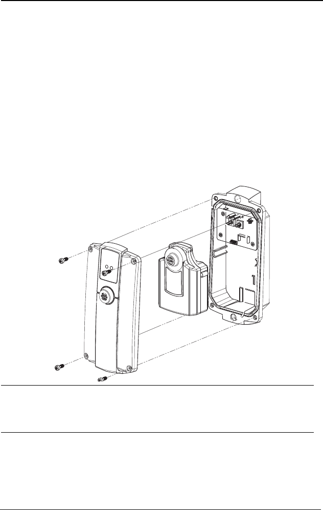
Changing the Sensor Cartridge
Since the sensor module is completely replaceable, you can simply
open the 301W transmitter, remove the depleted or defective S301W
cartridge and insert a new S301W cartridge. The sensor module is
equipped with a 16 pin (female) connector and needs only to be
pushed onto the connector pins in the 301W transmitter.
If the removed sensor is defective, return to Honeywell Analytics
according to the procedures described in the Warranty section of the
manual. If the unit has simply reached its End-of-life, discard according
to local Hazardous-Materials regulations (pcb and battery disposal).
CAUTION
Never remove the S301W cartridge when the transmitter is
functioning. Always power-off before opening the transmitter
(see How to Program the Transmitter; Function 9 - Save
Parameters and Close Device).
S301W
cartridge

DRAFT
511398 301W User Manual 29
4/07 Honeywell
Cartridge Replacement and Calibration
Remote Calibration
Remote Calibration
When using the 301W wireless transmitter in a network of sensors,
connected to a 301C wireless controller, it is possible to perform a
“remote calibration” using the 301C wireless controller menu:
1. Using the navigation arrows, access the 301C wireless
controller’s menu
2. Scroll through the menu options and select option 7.
Network
3. Scroll through the Network options screens to the last screen
and select the Calibration option
7. Network
Statistics
Calibration
DRAFT
30 301W User Manual 511398
Honeywell 4/07
Cartridge Replacement and Calibration
Remote Calibration
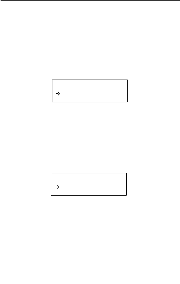
The Calibration screen contains four (4) lines of information:
Line 1: Indicates the mode (Calib), the device address for calibration
and the type of device to calibrate (301W)
Line 2: Indicates the status (Normal or In Calib...) of the specified
device
Line 3: Displays the function to perfom (Set Zero)
Line 4: Displays the function to perform (Set Span) and the
calibration concentration (246 PPM)
1. On the first line, scroll to the device address and press Enter
2. Scroll through the devices to display the desired device* and
press Enter to select.
3. The second line displays the device’s status
4. Scroll to select the desired function, Set Zero to set the
device’s zero
5. Upon selecting Set Zero, the controller requests
confirmation.
6. Pres Enter to confirm or Esc to cancel. If confirmed, the
controller sets the 301W’s zero. This takes only a few
moments and returns to the default calibration screen.
Note: Never calibrate the sensor zero with ambiant air only. Always
use Nitrogen (N2).
* The device must be configured in the 301CW’s database in order to
be included in the device addresses displayed on screen.
Calib 007 301W
Status: Normal
Set Zero
Set Span 246 PPM
Calib 007 301W
Calibrate Zero?
Set Zero
Set Span 246 PPM

DRAFT
511398 301W User Manual 31
4/07 Honeywell
Cartridge Replacement and Calibration
Periodic Inspections and Calibration
1. To set the device Span**, scroll to Set Span and change the
calibration value using this procedure:
a. Using the right arrow, move the cursor to xxx PPM (span value
field). Press Enter to select the field.
b. Use the up or down arrows to increase or decrease the value
(according to the calibration gas concentration).
c. Move the cursor back to Set Span and press Enter to validate
the calibration gas value and start the calibration.
The device span is being calibrated. The screen will displays the
device’s status as “In Calib” until the calibration is complete.
**When selecting Set Span, make sure that the device has been
exposed to the appropriate calibration gas, before and throughout the
calibration process.
Periodic Inspections and Calibration
Although the wireless transmitter is maintenance free, regular
inspections may still be necessary. The inspection frequency depends
on operating conditions, including operating under extreme
temperatures, exposure to contaminants or gas concentrations greater
than the lower explosive limits. A calibration inspection must be
included as part of a routine maintenance to ensure proper operation of
the gas detection unit.
Calib 007 301W
Status: Normal
Set Zero
Set Span 246 PPM
DRAFT

DRAFT
511398 301W User Manual 33
4/07 Honeywell
Troubleshooting
Troubleshooting
Consult the Programming Functions section of this manual for more
detailed information on transmitter blinking sequences and
programming.
Consult the 301C controller user manual for more detailed information
on using the controller’s wireless network menu.
Problem Possible Cause Solution
The transmitter
is not
connected to
301C controller
The transmitter has not
been powered up
Press pushbutton 1, then
pushbutton 2. If the transmitter is
on, LED 2 will blink once. If no
LEDs blink the unit is off and you
must power up the transmitter:
Press and hold pushbuttons 1 and
2. Count 5 blinks of both LEDs
and release.
Enable the 301C’s Association
mode (wireless Network menu)
Communication
problems:
The network can take up
to 2 hours to establish all
connections. Times are
affected by network
structure: Less
transmitters close to
301C, more time to
establish link); Distance
between furthest
transmitter and 301C
(more hops); Size of
network (the more
transmitters, the longer it
takes)
Make sur the unit is powered up
(see above)
Check that devices closer to 301C
are connected (is the unit closest
to it connected)
Activate a scan of all channels
(see Function 4 -Scan All
Channels ) and wait 30 minutes
Activate the 301C’s Association
mode and wait 50 minutes.
Reset network parameters (see
Function 5 -Reset Network
Parameters to Zero) and wait 50
minutes
If the transmitter has still not
connected, contact Technical
Support.

DRAFT
511398 301W User Manual 34
4/07 Honeywell
Troubleshooting
Tran sm i tt er
connected but
appears in fault
status -F-
Various hardware or
software statuses:
Device status:
B5= Battery weak
B4= Hibernation mode
B3= Service mode
activated
B2= Hardware error
(memory)
B1= Hardware error
Sensor status:
B15= Alarm B
B14= Alarm A
B13= Service alarm
B12= Hardware error
(CPU)
B11= Hardware error
(sensor)
B10= Not calibrated
B9= In calibration
B7= Alarm C
Check the transmitter (device and
sensor) status in the 301C TX Info
menu. Hardware errors require
the following procedure:
Shut transmitter down (Function 9
- Save Parameters and Close
Device), remove battery and
reinstall and power transmitter
back up.
If the error does not resolve,
contact technical support.
LED 2 blinks
when
pushbutton 1 is
pressed
The transmitter is busy
performing another
function
Wait several minutes and try
again. Ongoing functions can also
be cancelled by pressing both
pushbuttons simultaneously for 2
blinks, then releasing.
Both LEDs blink
at power up, too
fast to count
Contact technical support
LEDs blink in
rapidly
alternating
sequence
Transmitter battery is too
weak
Replace battery
LEDs blink a
function code
past the initial
power up
minute
Transmitter is in service
mode
Deactivate Service mode from
301C menu or directly on the
transmitter (see Function 2 -
Activate or Deactivate Service
Mode)
Problem Possible Cause Solution

DRAFT
511398 301W User Manual 35
4/07 Honeywell
Troubleshooting
Intermittent
communication
problems with
one or several
transmitters
The network can take up
to 12 hours to fully
stabilize
Wait the initial 12 hour period and
contact technical support.
Problem Possible Cause Solution
DRAFT

DRAFT
511398 301W User Manual 37
4/07 Honeywell
Specifications
Gases Detected
Specifications
Gases Detected
Power: One 3.6 V, 19 AH battery (supplied by sensor
module)
Alarm levels: Gas Alarm A Alarm B Alarm C
CO 25 ppm 200 ppm 225 ppm
NO2 0.72ppm 2.0ppm 9.0ppm
O2 19.5% vol 22.0% vol 22.5% vo
Detection range: CO: 0 to 250 ppm
NO2: 0 to 6 ppm
O2: 0 to 25%
Operating Pressure range: 95 to 110 kPa
Communication: 2.4 GHz ISM wireless
Communication range: 30 m indoor
Visual Indicators: 2 LEDs (with pushbutton interfaces)
Dimensions: 22.5 x 10 x 5.7cm
8.85” x 4” x 2.25”
Certification: FCC ID: U5C301W-1
IC: 573P-301W1
Gas Operating
Temperature
Operating
Humidity
Accuracy
at 25ºC Resolution T90
CO -20°C to 50°C
(-4 °F to 122 °F)
15 - 95% non-
condensing ± 10 ppm 7 ppm <30 sec
NO2-20°C to 50°C
(-4 °F to 122 °F)
15 - 95% non-
condensing ± 0.2 ppm 0.02 ppm <30 sec
O2-20°C to 50°C
(-4 °F to 122 °F)
15 - 95% non-
condensing ± 0.2 % 0.1% <15 sec

DRAFT
511398 301W User Manual 38
4/07 Honeywell
Specifications
FCC Specifications
FCC Specifications
Note: This equipment has been tested and found to comply with the
limits for a Class A digital device, pursuant to part 15 of the FCC
Rules. These limits are designed to provide reasonable protection
against harmful interference when the equipment is operated in a
commercial environment. This equipment generates, uses, and
can radiate radio frequency energy and, if not installed and used
in accordance with the instruction manual, may cause harmful
interference to radio communications. Operation of this
equipment in a residential area is likely to cause harmful
interference in which case the user will be required to correct the
interference at his own expense.
This device complies with Part 15 of the FCC Rules.
Operation is subject to the following two conditions: (1)
this device may not cause harmful interference, and (2)
this device must accept any interference received,
including interference that may cause undesired
operation.
The internal / external antennas used for this mobile
transmitter must provide a separation distance of at least
20 cm from all persons and must not be co-located or
operating in conjunction with any other antenna or
transmitter."
Modifications not expressly approved by this company
could void the user's authority to
operate the equipment.
Qualified personnel must install radio communication
devices. Improper installation or selection of a
transmitter’s location may cause intermittent or unreliable
performance

DRAFT
511398 301W User Manual 39
4/07 Honeywell
Limited Warranty
Limited Warranty
Honeywell Analytics, Inc. warrants to the original purchaser and/or
ultimate customer ("Purchaser") of Vulcain products ("Product") that if
any part thereof proves to be defective in material or workmanship
within twelve (12) months, such defective part will be repaired or
replaced, free of charge, at Honeywell Analytics' discretion if shipped
prepaid to Honeywell Analytics at 4005 Matte Blvd., Unit G, Brossard,
Quebec, J4Y 2P4, in a package equal to or in the original container.
The Product will be returned freight prepaid and repaired or replaced if
it is determined by Honeywell Analytics that the part failed due to
defective materials or workmanship. The repair or replacement of any
such defective part shall be Honeywell Analytics' sole and exclusive
responsibility and liability under this limited warranty.
Re-Stocking Policy
The following restocking fees will apply when customers return products
for credit:
• 15% restocking fee will be applied if the product is returned within 1
month following the shipping date
• 30% restocking fee will be applied if the product is returned within 3
months following the shipping date
A full credit (less restocking fee) will only be issued if the product is in
perfect working condition. If repairs are required on the returned
product, the cost of these repairs will be deducted from the credit to be
issued.
No credits will be issued beyond the three month period.

DRAFT
511398 301W User Manual 40
4/07 Honeywell
Limited Warranty
Exclusions
A. If Gas sensors are part of the Product, the gas sensor is
covered by a twelve (12) month limited warranty of the manufacturer.
B. If gas sensors are covered by this limited warranty, the gas
sensor is subject to inspection by Honeywell Analytics for extended
exposure to excessive gas concentrations if a claim by the Purchaser is
made under this limited warranty. Should such inspection indicate that
the gas sensor has been expended rather than failed prematurely, this
limited warranty shall not apply to the Product.
C. This limited warranty does not cover consumable items, such
as batteries, or items subject to wear or periodic replacement, including
lamps, fuses, valves, vanes, sensor elements, cartridges, or filter
elements.
Warranty Limitation and Exclusion
Honeywell Analytics will have no further obligation under this limited
warranty. All warranty obligations of Honeywell Analytics are
extinguishable if the Product has been subject to abuse, misuse,
negligence, or accident or if the Purchaser fails to perform any of the
duties set forth in this limited warranty or if the Product has not been
operated in accordance with instructions, or if the Product
serial number has been removed or altered.

DRAFT
511398 301W User Manual 41
4/07 Honeywell
Limited Warranty
Disclaimer of Unstated Warranties
The warranty printed above is the only warranty applicable to this
purchase. All other warranties, express or implied, including, but not
limited to, the implied warranties of merchantability or fitness for a
particular purpose are hereby disclaimed.
Limitation of Liability
It is understood and agreed that Honeywell Analytics’ liability, whether
in contract, in tort, under any warranty, in negligence or otherwise shall
not exceed the amount of the purchase price paid by the purchaser for
the product and under no circumstances shall Honeywell Analytics be
liable for special, indirect, or consequential damages. The price stated
for the product is a consideration limiting Honeywell Analytics' liability.
No action, regardless of form, arising out of the transactions under this
warranty may be brought by the purchaser more than one year after the
cause of actions has occurred.
DRAFT