Honeywell Enraf 970SR Tank level measuring gauge User Manual K 970 IN GUIDE 4416717 717REV00 717 REV0 WPD
Honeywell Enraf Tank level measuring gauge K 970 IN GUIDE 4416717 717REV00 717 REV0 WPD
UserManual.wiki
>
Honeywell Enraf
>
970SR User Manual
User Manual
Navigation menu
Upload a User Manual
Namespaces
Wiki Guide
HTML
PDF
Info
Views
User Manual
Discussion / Help
Navigation
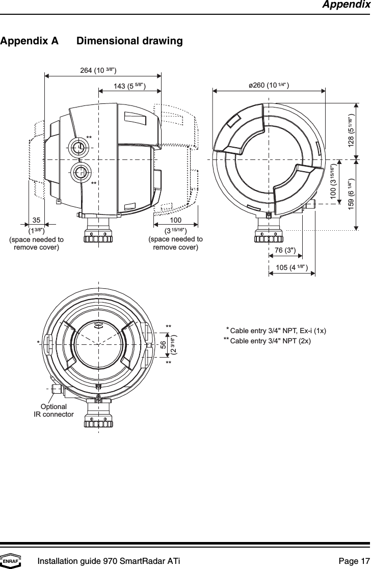
![SafetyPage 4WarningDo not use the instrument for anything else than its intended purpose.WarningImproper installation of cable glands, conduits or stopping plugs will invalidate theEx approval of the 970 SmartRadar ATi.SafetySafety aspects of 970 SmartRadar ATiThe housing of the 970 SmartRadar ATi is explosion proof:• II 1/2 G EEx de [ia/ib] II B T4; KEMA 03ATEX2468 X; certified by KEMA, Netherlands• Class I, Division 1, Groups B, C, D T4, according to ANSI / NFPA 70 (Factory Mutual)Environmental conditions for the SmartRadar ATi are:ambient temperature : -40 to 60 °C (-40 to 140 °F)operating pressure : max. 6 barrelative humidity : 0 - 100 %ingress protection : IP67The emitted microwave energy is far below acceptable limits for exposure to the human body.Depending on the type of antenna, a maximum radiation of 0.1 mW/cm is generated.2](https://usermanual.wiki/Honeywell-Enraf/970SR/User-Guide-466720-Page-4.png)
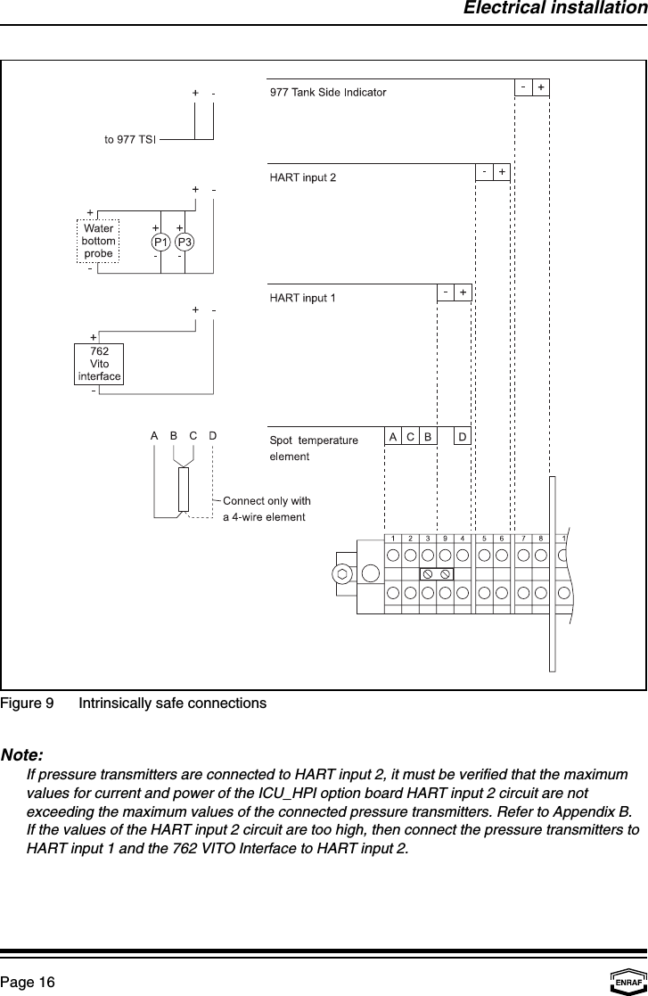
![AppendixPage 18Appendix B ATEX ApprovalThe terminal compartment of the 970 SmartRadar ATi has been ATEX approved as explosion-proof and as being increased safe. The type of cable glands that must be used:For protection type increased safe EEx e approved glands are to be used.For protection type explosion-proof EEx d approved glands or conduits are to be used.Connection requirements of optional boardsThe identification label on the 970 SmartRadar ATi indicates whether your instrument is equippedwith an optional board with intrinsically safe measuring circuits.I.S. option for Tank Side Indicator, [EEx ib] IIB:Output circuit for 977 TSI:Max. values : U = 21 V, I = 325 mA, P = 1.5 WMax. permissible ext. inductance : 1.4 mHMax. permissible ext. capacitance : 1.27 µFICU_HPI option board SPOT, [EEx ia] IIB:Spot temperature input circuit:Max. values : U = 23.1 V, I = 221 mA, P = 0.19 WMax. permissible ext. inductance : 3.5 mHMax. permissible ext. capacitance : 980 nFICU_HPI option board HART1, [EEx ia] IIB:HART input 1 circuit (for 762 VITO interface):Max. values : U = 23.1 V, I = 90 mA, P = 0.52 WMax. permissible ext. inductance : 15 mHMax. permissible ext. capacitance : 1.02 µFICU_HPI option board HART2, [EEx ia] IIB:HART input 2 circuit (for HART pressure transmitters and/or external water probe):®Max. values : U = 23.1 V, I = 148 mA, P = 0.68 WMax. permissible ext. inductance : 7 mHMax. permissible ext. capacitance : 1.02 µF](https://usermanual.wiki/Honeywell-Enraf/970SR/User-Guide-466720-Page-18.png)