Honeywell orporated DR4201 DIGITAL KEY READER User Manual Digireader
Honeywell International Incorporated DIGITAL KEY READER Digireader
UserManual.wiki
>
Honeywell orporated
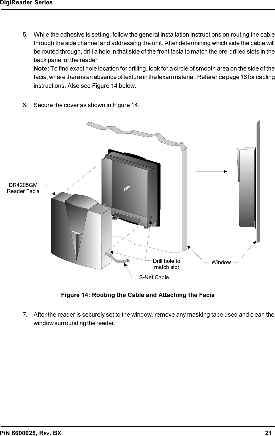
>
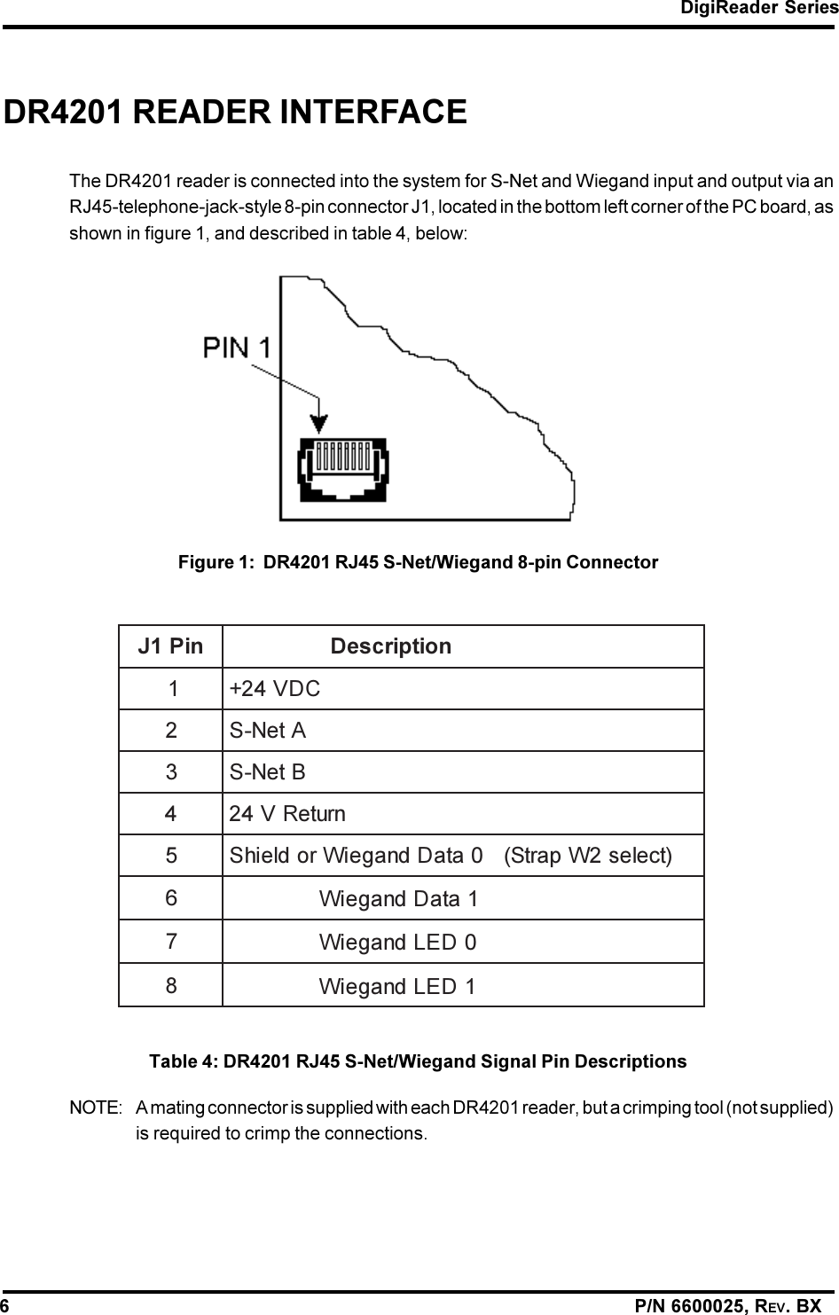
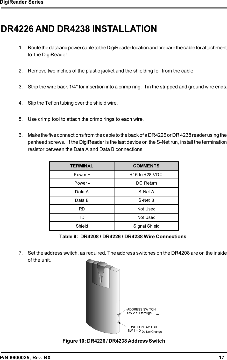
DR4201 User Manual
USERS MANUAL
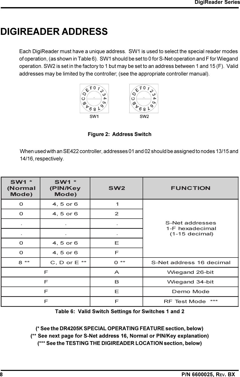
Navigation menu
Upload a User Manual
Namespaces
Wiki Guide
HTML
PDF
Info
Views
User Manual
Discussion / Help
Navigation