Honeywell orporated DR4201 DIGITAL KEY READER User Manual Digireader
Honeywell International Incorporated DIGITAL KEY READER Digireader
USERS MANUAL

DigiReader Series
P/N 6600025, REV. BX 1
INTRODUCTION
The DigiReader DR4200 Series Digital Proximity Readers (DigiReaders) are security devices that
reads digital credentials at ranges from 1 to 36 inches (2½ to 91 cm) depending upon the model and
the environmental conditions. DR4200 Series DigiReaders are bi-directional, so that a credential can
be read from either side of the sensor. DR4200 Series DigiReaders are used with the NexSentry 4100
Family, SE818SC and SE422 ACUs operating as stand-alone devices or in conjunction with a
NexSentry Manager, an SE6000 (a NexSentry Command Center NSCC) or an SE5850, (WSE
access control host systems). Connection between DigiReaders and an ACU is over the WSE
proprietary S-Net interface or over a Wiegand interface to a Wiegand ACU. The Wiegand data can
be either 26- or 34-bit Wiegand standard.
CAUTION 1. Read this manual carefully before attempting to wire in place a DR4200 Series
DigiReader. The warranty is void if damage occurs to the unit as a result of
incorrect wiring.
CAUTION 2. The information in this manual is not intended to conflict with the building codes,
electrical codes, fire codes, or safety codes required for any given installation.
In all cases, the prevailing building codes must take precedence.

DigiReader Series
2 P/N 6600025, REV. BX
GENERAL SPECIFICATIONS
Table 1: Digital Reader Specifications
*See Table 1A for details on DR4205 Readers
1024RD 3024RD *seireS5024RD 6224RD 8324RD
noitpircseD
/tsoctsewoL
rofredaertsellams
'hctiwsthgil'
sgnitnuomepyt
ytimixorplatigiD
roodrofredaer
snoillum
sngisedtnereffiD
sgnitnuomdna
*seiresnihtiw
ytimixorplatigiD
htiwredaer
daerdesaercni
egnar
ytimixorplatigiD
htiwredaer
daermumixam
egnar
)sehcnI(snoisnemiD2.0x7.0x8.12.1x5.7x8.1* 3.1x0.9x8.719.1x8.31x9.52
).mC(snoisnemiD5.0x8.1x5.40.3x0.91x5.4* 2.3x9.22x2.548.4x0.53x8.56
ycneuqerFtimsnarTnoitarepoxelpudlluf,zhK041
ycneuqerFrevieceRzHk07
revieceR
noitaludomeD langis)KSP(yeKtfihS-esahP
elcyCdaeRdraCcesm001
ecruoSrewoPAm08nahtssel,CDV42-61*
6.0,CDV42-61
lanimonpma
7.0,CDV42-61
lanimonpma
aivderewoPeriwriapdetsiwtten-S
noitapissiDrewoPsttaw2nahtsseL sttaw71nahtsseL
srellortnoC224ES,CS818otlA,seireS0014yrtneSxeN
rellortnocotecafretnI snoitacinummocteN-S;584-SR,)dedleihs,GWA22(riapdetsiwtlauD
srotacidnIelbammargorp,)der-wolley-neerg(roloc-irtelgniS
noitcetorPrepmaTseY
ytidimuH %09ot%01
)gnisnednoc-non(
%09ot%01
gnisnednoc *gnisnednoc%09ot%01
(erutarepmeT)F°051ot13-051ot13-* 041ot4-
(erutarepmeT)C°66ot53-66ot53-* 06ot02-
tnemnorivnEylnoesuroodnIesuroodtuO/roodnI* esuroodtuOdnaroodnI
).sbL(thgieW52.01<*5<01<
)smargK(thgieW211.054.0<*3.2<5.4<
tnailpmocADA lausivdnaelbidua,sseccaeerf-sdnah:edulcnisseccadelbasidgnisaerofserutaeflaicepS;seY
sutatssseccaetacidniotsrotacidni
egnaRdaeR.xaM 1024RD 3024RD 5024RD 6224RD 8324RD
)stinU()sehcnI().mC()sehcnI().mC()sehcnI().mC()sehcnI().mC()sehcnI().mC(
yeKardauQ5.1otpu8.3otpu3otpu6.7otpu4otpu01otpu31otpu33otpu22otpu55otpu
yeKxeN5.1otpu8.3otpu3otpu6.7otpu4otpu01otpu31otpu33otpu22otpu55otpu
yeKaruD5.1otpu8.3otpu4otpu01otpu6otpu51otpu22otpu55otpu63otpu19otpu
etaMyeK1otpu5.2otpu1otpu5.2otpu2otpu5otpu21otpu03otpu51otpu83otpu
gaTaruD1otpu5.2otpu1otpu5.2otpu2otpu5otpu01otpu52otpu51otpu83otpu
.noitallatsnifotnemnorivnelacisyhpnognidnepedyravyamegnardaermumixaM

DigiReader Series
P/N 6600025, REV. BX 3
DR 4205 SERIES SPECIFICATIONS
Table 1A: DR4205 Series Specifications
5024RD E5024RD MG5024RD K5024RD W5024RD EW5024RD MGW5024RD
noitpircseD
latigiD
ytimixorp
redaer
latigiD
ytimixorp
rofredaer
esulanretxe
latigiD
ytimixorp
htiwredaer
foytilibapac
ssalggnieb
detnuom
latigiD
ytimixorp
htiwredaer
detargetni
foorpretaw
rofdapyek
dnaroodni
esuroodtuo
dnageiW
ytimixorp
redaer
dnageiW
ytimixorp
rofredaer
esulanretxe
dnageiW
ytimixorp
htiwredaer
foytilibapac
ssalggnieb
detnuom
snoisnemiD)mc2.3x6.41x5.31("72.1x"47.5x"3.5
timsnarT
ycneuqerF noitarepoxelpudlluf,zhK041
revieceR
ycneuqerF zHk07
revieceR
noitaludomeD langis)KSP(yeKtfihS-esahP
elcyCdaeRdraCcesm001
ecruoSrewoPAm08nahtssel,CDV42-61 Am08nahtssel,CDV42-8
aivderewoPeriwriapdetsiwtten-S
noitapissiDrewoPsttaw2nahtsseL
srellortnoC224ES,CS818otlA,seireS0014yrtneSxeN dnageiWyrtneSxeN.seireS0014yrtneSxeN
d'qeRtinUecafretnI
otecafretnI
rellortnoc
teN-S;584-SR,)dedleihs,GWA22(riapdetsiwtlauD
snoitacinummoc
-SR,)dedleihs,GWA22(riapdetsiwTlauD
-5tib-43ro-62;snoitacinummocteN-S;584
dnageiWyrtneSxeN;dradnatsdnageiWeriw
deriuqertinUecafretnI
srotacidnIelbammargorp,roloc-irtelgniS
noitcetorPrepmaTseY
ytidimuH %09ot%0
gnisnednoc
%001ot%5
gnisnednoc
%09ot%01
gnisnednoc
%001ot%5
gnisnednoc
%09ot%01
gnisnednoc
%09ot%5
gnisnednoc
%09ot%01
gnisnednoc
(erutarepmeT)F°051ot91051ot13-051ot91051ot13-051ot91051ot13-051ot91
erutarepmeT)C°(66ot7-66ot53-66ot7-66ot53-66ot7-66ot53-66ot7-
tnemnorivnE esuroodnI
ylno
dezirehtaeW
-hsalpsdna
roffoorp
esuroodtuo
esuroodnI
ylno
dezirehtaeW
-hsalpsdna
roffoorp
esuroodtuo
esuroodnI
ylno
dezirehtaeW
-hsalpsdna
roffoorp
esuroodtuo
esuroodnI
ylno
)secnuO(thgieW51429151214291
)smarG(thgieW024276235024043276235
tnailpmocADA srotacidnilausivdnaelbidua,sseccaeerf-sdnah:edulcnisseccadelbasidgnisaerofserutaeflaicepS;seY
sutatssseccaetacidniot
mumixaM
egnaRdaeR sledoM5024RDllA
)stinU()sehcnI()sretemitneC(
yeKardauQ4otpu01otpu
yeKxeN4otpu01otpu
yeKaruD6otpu51otpu
etaMyeK2otpu5otpu
gaTaruD2otpu5otpu

DigiReader Series
4 P/N 6600025, REV. BX
BASIC OPERATION
DigiReaders emit a low-level 140-kHz field. When a digital credential card is placed in this field, a
digital chip embedded in the key uses the fields energy to become activated. Once activated, the
key responds by broadcasting a 70-kHz signal, modulated with a key-specific code sequence, back
to the reader. The reader receives this signal and converts it to a digital code which is then sent to
the Controller. The Controller identifies the digital credential according to its code and makes either
an access granted or an access denied decision.
DR4205K (/W) has a keypad on the face of the DigiReader. The key pad is used to enter the users
Personal Identification Number (PIN). (See the appropriate Controller or security management
system manual for details on PIN assignment.)
The user may enter his or her own PIN. The LED turns amber, and then the user presents a digital
credential; or the user may first present the key, the LED turns amber, and then the user enters the
PIN. The time allotted for this procedure is defined by the PIN GRACE PERIOD which is set with
the Controller SYSTEM command. (See the appropriate Controller or security management system
manual for information on setting this parameter.) If an error is made in entering the PIN, the user
may press the "*" key to clear the keypad and begin entry again.
The keypad versions can be configured for keypad-only use or credential-only use. Refer to your
controller manual or security management system manual for details on setup and configuration.
DR4200K is just the keypad part of the DR4205K.
LED OPERATION
LED (S-NET OPERATION)
When the DigiReader is on line, the LED is red during the ready state. The TUNE command is used
to specify LED and beeper behavior when a valid key is presented. An equivalent of the tune
command may be found in each WSE security management system system.
DigiReaders have a single three-color LED that can be controlled by the Controller. If power is applied
to the unit when not connected to a Controller, or improperly configured at the Controller, the LED
acts as follows: Flashes red four times in four seconds, changes to steady amber for four seconds
and then turns off for 52 seconds. When a key is presented, the sensor beeps four times, and the
LED flashes amber until the key is moved out of range. The flashing red, steady amber, off cycle
then resumes and repeats indefinitely while power is supplied.
DigiReader Series
P/N 6600025, REV. BX 5
LED (WIEGAND OPERATION)
The LED is controlled to be red or green by the level of the Wiegand LED control input.
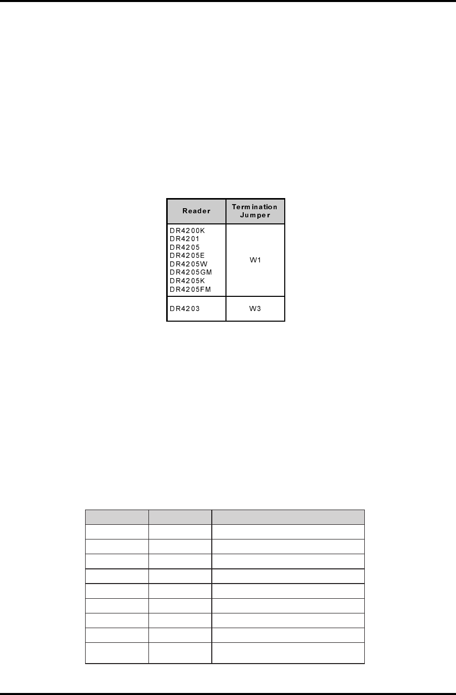
120-OHM TERMINATION JUMPER
The internal jumper places 120 ohms of resistance between Data A and Data B for proper end-of-
line termination. Install the jumper only if the DR4200 Series DigiReader is the last device on the
cable. If you are using:
If you are using the DR4208, DR4226 or DR4238, an external 120 ohm, 1/4 watt resistor must be
used. There is no internal jumper on these models. The jumper is only available on surface mount
technology (SMT) models.
INTERNAL INTERFACE CABLE
An attached cable provides the connection from the printed-circuit assembly and keyboard to the
access control unit wiring on all DigiReaders except for the DR4201, DR4208, DR4226 and the
DR4238. The cable is color coded as follows:
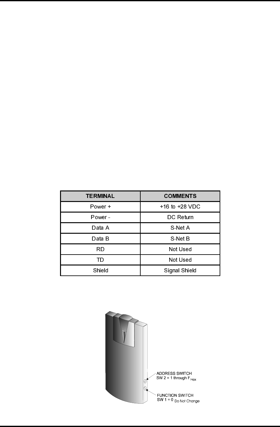
Table 3: Internal Interface Cable
ROLOC NOITCNUF STNEMMOC
deRCDV82+ot61+)lanimoN(
kcalBnruteRCD
neerGAteN-SslenaplortnocsseccaESWhtiwesuroF
etihWBteN-SslenaplortnocsseccaESWhtiwesuroF
eulB0ataDslenaplortnocsseccadnageiWhtiwesuroF
egnarO1ataDslenaplortnocsseccadnageiWhtiwesuroF
wolleY0DELslenaplortnocsseccadnageiWhtiwesuroF
nworB1DELslenaplortnocsseccadnageiWhtiwesuroF
dleihSdleihSlangiS sseccadnageiWhtiwdesunehwnruteRCDoteiT
slenaplortnoc
Table 2: Termination Jumpers
DigiReader Series
6 P/N 6600025, REV. BX
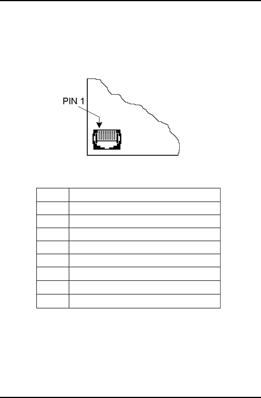
DR4201 READER INTERFACE
The DR4201 reader is connected into the system for S-Net and Wiegand input and output via an
RJ45-telephone-jack-style 8-pin connector J1, located in the bottom left corner of the PC board, as
shown in figure 1, and described in table 4, below:
Figure 1: DR4201 RJ45 S-Net/Wiegand 8-pin Connector
niP1JnoitpircseD
1CDV42+
2AteN-S
3BteN-S
4nruteRV42
5)tceles2WpartS(0ataDdnageiWrodleihS
61ataDdnageiW
70DELdnageiW
81DELdnageiW
Table 4: DR4201 RJ45 S-Net/Wiegand Signal Pin Descriptions
NOTE: A mating connector is supplied with each DR4201 reader, but a crimping tool (not supplied)
is required to crimp the connections.

DigiReader Series
P/N 6600025, REV. BX 7
ERUTCAFUNAM LACISYHP
NOITPIRCSED EGUAG
.tF0004<rewoPdnaataD elbaC&eriWtsewhtuoS
yarG/971WS
ataD:rotcudnoC2
rewoP:rotcudnoC2
GWA22
GWA61
.tF005<rewoPdnaataD 2559nedleB
9601nedleB dedleihSriaP-2 GWA81
GWA61
.tF005>ylnOataD1489nedleBdedleihSriaP-1GWA42
.tF005>ylnOrewoP
1439nedleB
2431nedleB
3439nedleB
rotcudnoC2
GWA81
GWA61
GWA41
RECOMMENDED S-NET CABLE
The type of cable used for the S-Net will depend on the total length and the number of devices
connected. Table 5 lists WSE recommended cables.
Table 5: Recommended S-Net Cable
SWITCHES
There are two switches on most DR4200 Series DigiReader printed circuit board, as follows,
(refer to Figure 2):
Switch SW1 is used to select between the S-Net or Wiegand operating modes.
Switch SW2 is used to set the S-Net address.
The DR4201 reader has a 5-position DIP-switch S1, which combines the functions of the rotary
address switches S1 and S2 used by the other DR4200 Series DigiReaders. This is described in
the DR4201 ADDRESS DIP-SWITCH section, below.
DigiReader Series
8 P/N 6600025, REV. BX
*1WS
lamroN(
)edoM
*1WS
(yeK/NIP
edoM)
2WS NOITCNUF
06ro5,41
sesserddateN-S
lamicedaxehF-1
)lamiced51-1(
06ro5,42
.. .
.. .
06ro5,4E
06ro5,4F
**8**EroD,C**0lamiced61sserddateN-S
FA tib-62dnageiW
FB tib-43dnageiW
FE edoMomeD
FF ***edoMtseTFR
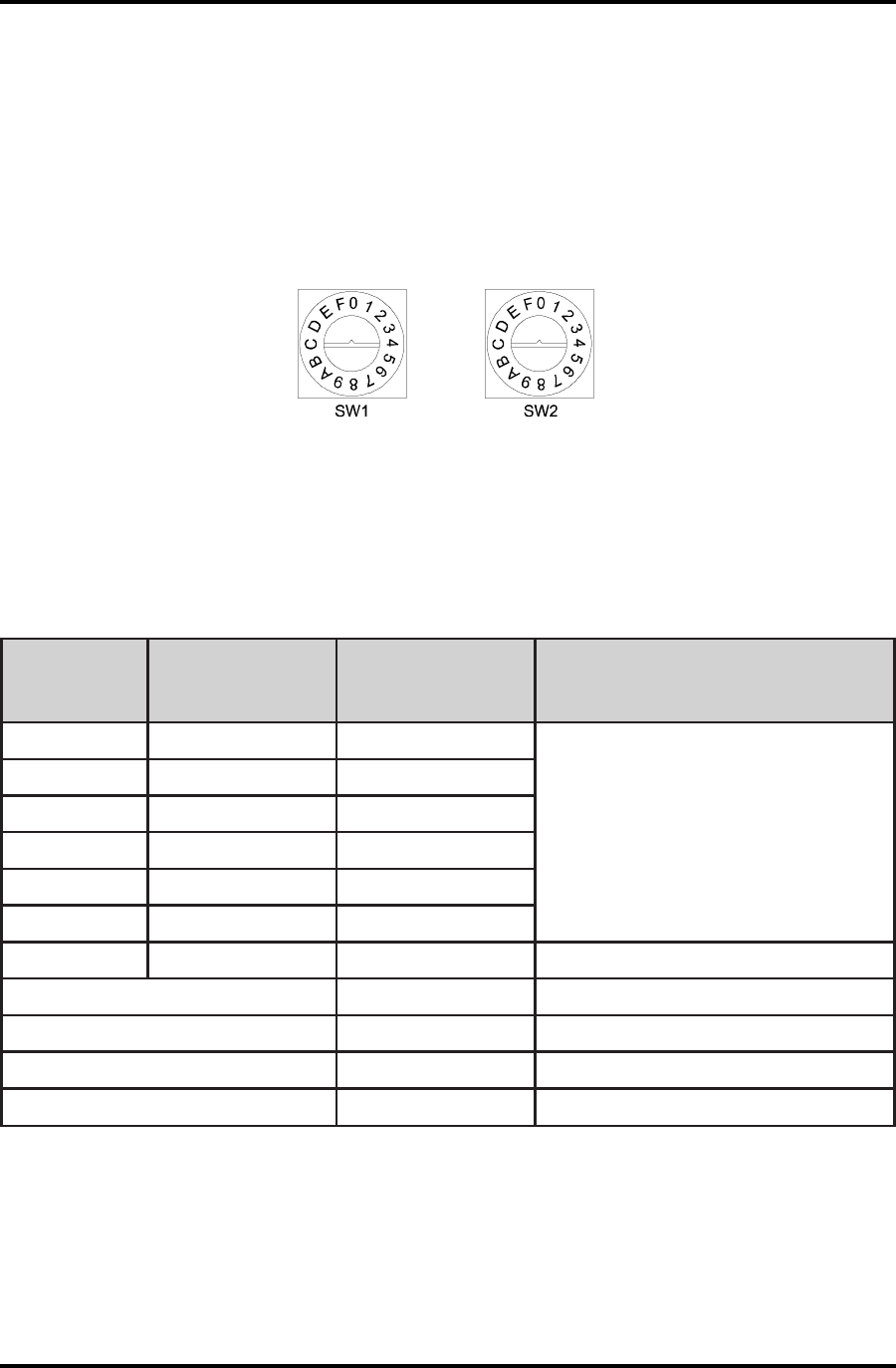
DIGIREADER ADDRESS
Each DigiReader must have a unique address. SW1 is used to select the special reader modes
of operation, (as shown in Table 6). SW1 should be set to 0 for S-Net operation and F for Wiegand
operation. SW2 is set in the factory to 1 but may be set to an address between 1 and 15 (F). Valid
addresses may be limited by the controller; (see the appropriate controller manual).
Figure 2: Address Switch
When used with an SE422 controller, addresses 01 and 02 should be assigned to nodes 13/15 and
14/16, respectively.
Table 6: Valid Switch Settings for Switches 1 and 2
(* See the DR4205K SPECIAL OPERATING FEATURE section, below)
(** See next page for S-Net address 16, Normal or PIN/Key explanation)
(*** See the TESTING THE DIGIREADER LOCATION section, below)

DigiReader Series
P/N 6600025, REV. BX 9
DR4205K SPECIAL OPERATING FEATURE
The DR4205K reader has two modes of operation, dependent on the setting of address switch SW1,
(which sets the upper byte of the address): the Normal Mode (SW1 = 0 or 8), and the PIN/Key Mode
(SW1 = 4, 5 or 6 or C, D or E). These two modes are described below.
NORMAL MODE
Address switch SW1 set to 0, the DR4205K operates in its normal mode. Address switch SW2
is then set to the physical S-Net address of the DR4205K: 1 through 9 and A through F (addresses
1 through 15). In order to address the 16th reader in the normal mode, SW1 = 8 and SW2 = 0.
Example: SW1 = 0 and SW2 = 1 to F sets normal mode for nodes #1-15;
SW1 = 8 and SW2 = 0 sets normal mode for node #16.
Operation in Normal Mode:
nDKR portion only enabled: the key is sent as a key, and no PIN is expected.
nVIP portion only enabled: the PIN is sent as a PIN, with the number of PIN digits to be
entered set in the SYSTEM command. No key is expected.
nBoth DKR and VIP portions enabled: the key is sent as a key, the PIN is sent as a PIN.
Both key and PIN are expected (in either order). The number of PIN digits to be entered
is set in the PIN DIGITS entry of the SYSTEM command.
PIN/KEY MODE
Address switch SW1 set to 4, 5 or 6, the DR4205K operates in its 'PIN/Key' mode, where: either
a) the PIN will be sent as a key, or b) the key will be sent as a PIN. The number of digits in the PIN
number is determined by the 4, 5 or 6 of switch SW1, and, again, address switch SW2 determines
the physical S-Net address of the DR4205K for nodes 1 to 15. In order to address the 16th reader
in the PIN/key mode, SW1 = C, D or E and SW2 = 0. NOTE: C = 8 + 4, D = 8 + 5 and E = 8 + 6.
Example: SW1-SW2 set as 41, 51 or 61, i.e. SW1 = 4, 5 or 6 and SW2 = 1 set node #1 in 'PIN/
Key' mode, for a 4-, 5- or 6-digit PIN, respectively; similarly for nodes 2 through 15; but
for node 16, for a 4-, 5- or 6-digit PIN, SW1-SW2 = C0, D0 or E0, respectively.
Operation in PIN/Key Mode:
nSW1 set to 4, 5, or 6 (or C, D or E): determines the number of PIN digits, 4, 5 or 6, (which
must match the number of digits set in the PIN DIGITS entry of the SYSTEM command)..
nDKR portion only enabled: the key is sent as a PIN.
nVIP portion only enabled: the PIN is sent as a key.
nBoth DKR and VIP portions enabled: the key is sent as a key, the PIN is sent as a PIN.
Both key and PIN are expected (in either order). The number of PIN digits to be entered
is set both in SW1 and in the PIN DIGITS entry of the SYSTEM command. (Note that with
both the DKR and VIP portions enabled the operation is the same as for the normal mode.)
DigiReader Series
10 P/N 6600025, REV. BX
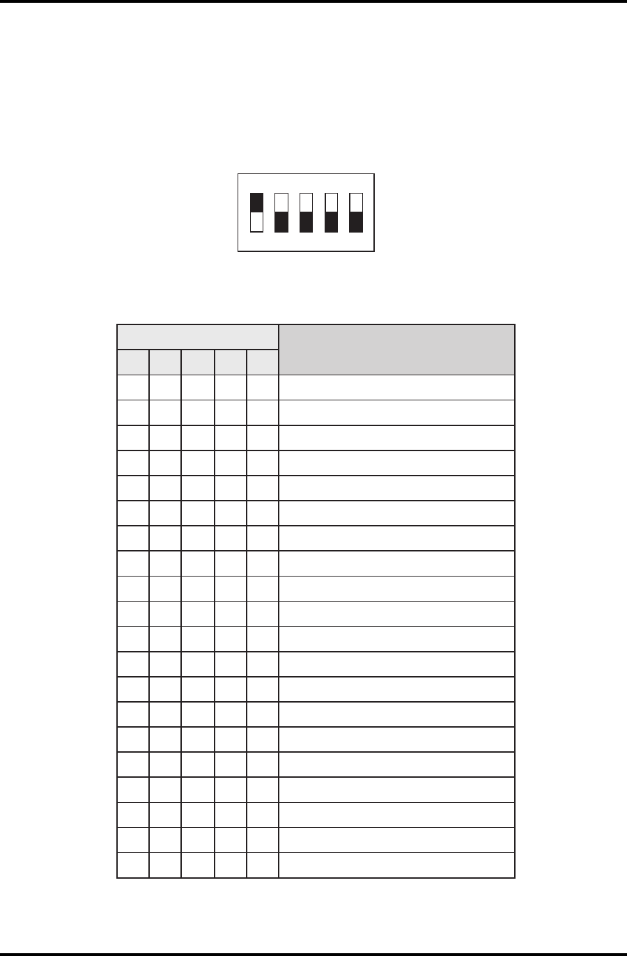
DR4201 ADDRESS DIP-SWITCH
The DR4201 reader has a single 5-position DIP-switch S1 for address selection, see figure 3, below,
which demonstrates S-Net address 1 being selected. Table 7, below, shows the possible
addressing selections.
Figure 3: DR4201 Address DIP-Switch Showing S-Net Address 1 Selected
Table 7: DR4201 Address DIP-Switch Selections
)sgnitteS(1ShctiwS
noitcnuF/sserddAteN-S
1 2 3 4 5
nO ffOffOffOffO1
ffO nO ffOffOffO2
nOnOffOffOffO3
ffOffO nO ffOffO4
nO ffO nO ffOffO5
ffO nOnOffOffO6
nOnOnOffOffO7
ffOffOffO nO ffO8
nO ffOffO nO ffO9
ffO nO ffO nO ffO01
nOnOffO nO ffO11
ffOffO nOnOffO21
nO ffO nOnOffO31
ffO nOnOnOffO41
nOnOnOnOffO51
ffOffOffOffO nO 61
ffO nO ffO nOnO)tib-62(ecafretnIdnageiW
ffOffO nOnOnO)tib-43(ecafretnIdnageiW
ffO nOnOnOnOedoMOMED
nOnOnOnOnOedoMTSET
NO
12 3 45
FFO
DigiReader Series
P/N 6600025, REV. BX 11
TAMPER SIGNAL (S-NET ONLY)
DR4200 Series DigiReaders send a tamper signal to an S-Net-based Controller each time an
address switch (SW1 or SW2, described above) is changed. Note that the DR4208, DR4226 and
DR4238 have physical tamper switches.
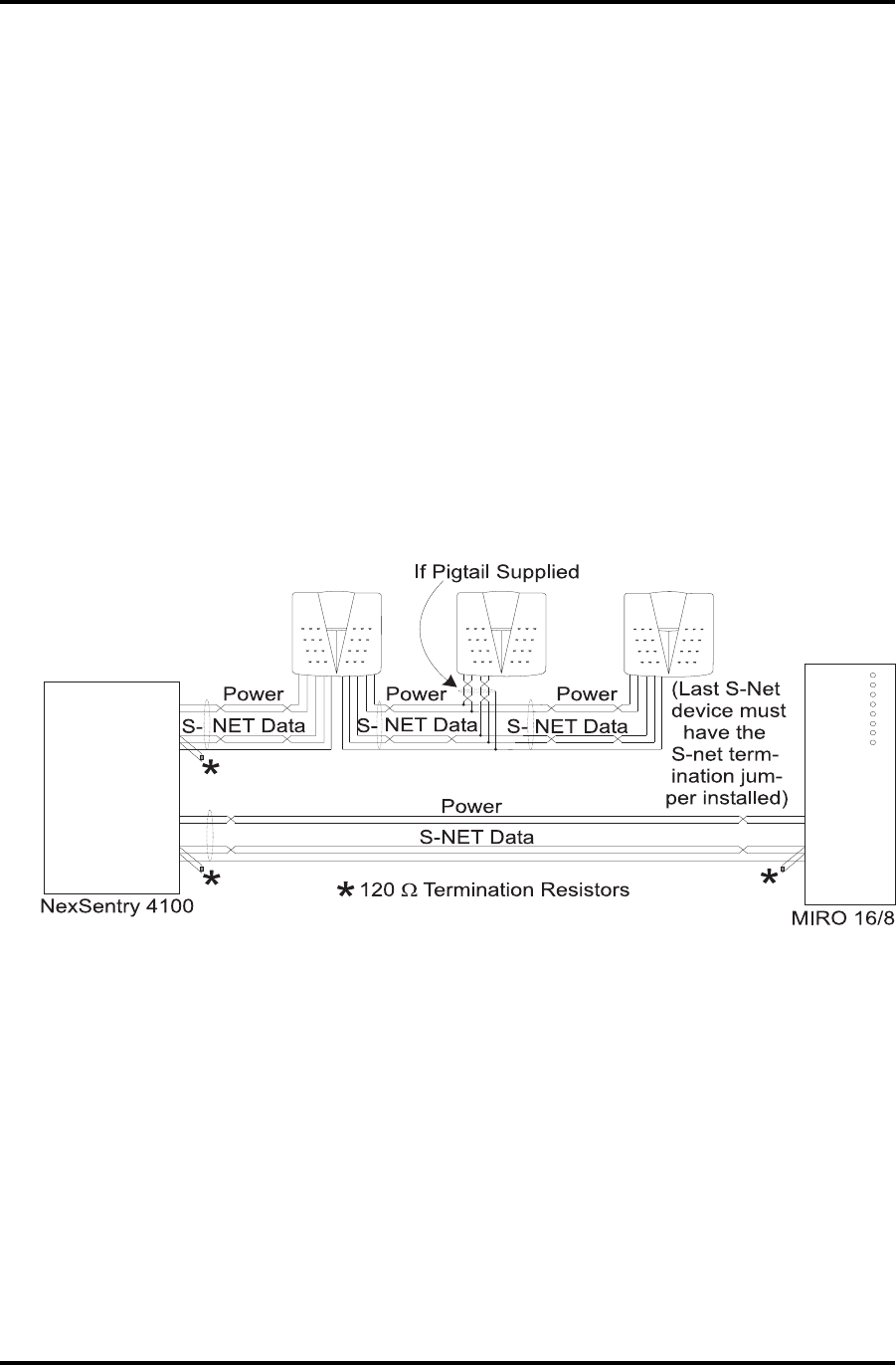
S-NET CONNECTIONS
The S-Net is an RS485 serial network for communication between the Controller and node devices.
Typically, the cable used is two twisted pairs with an overall shield; one pair is for data, the other
pair is for DC power. Terminate the last S-Net device with a 120-ohm, ¼ watt resistor or termination
jumper as shown in Figure 2. The maximum S-Net length is 4000 feet (1200 meters).
Figure 4: S-Net Wiring
S-Net cable should only be installed in a daisy-chained fashion. WSE strongly recommends
replacing all crimp lug/soldered splices by daisy-chained connections in and out of each device.
(Note that up to two AD4305 NexStar RS485 Multiplexers may be used to simplify wiring and extend
a network.)
Where a pigtail cable is provided with reader, splices are required and the installer should try to keep
the splice within 3 feet of the reader, if possible, to allow splice inspection at the reader location.
The type of cable used for the S-Net will depend on the total length and the number of devices
connected. Separate twisted-pair cables should be used for data and power when the S-Net exceeds
500 feet (152 meters). See Table 4 for WSE recommended cables.
DigiReader Series
12 P/N 6600025, REV. BX
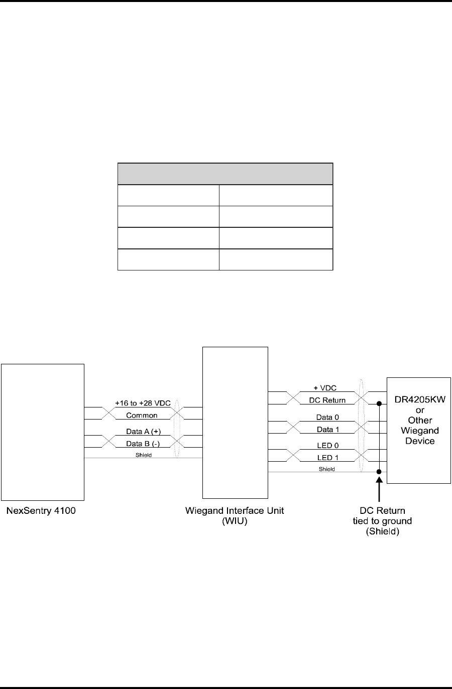
WIEGAND CONNECTIONS
Refer to the following table for the proper wire size for a particular cable length to use in a DigiReader
Wiegand application.
(NOTE: For the DR4201, jumper W2 must be in place for Wiegand to be operative.)
Table 8: Recommended Wiegand Cable Gauge
DLEIHSHTIWELBACDNAGEIWROTCUDNOC-6
eziSeriWmuminiMhtgneLmumixaM
GWA22teeF002
GWA02teeF003
GWA81teeF005
Figure 5: Typical Wiegand Connection
DigiReader Series
P/N 6600025, REV. BX 13
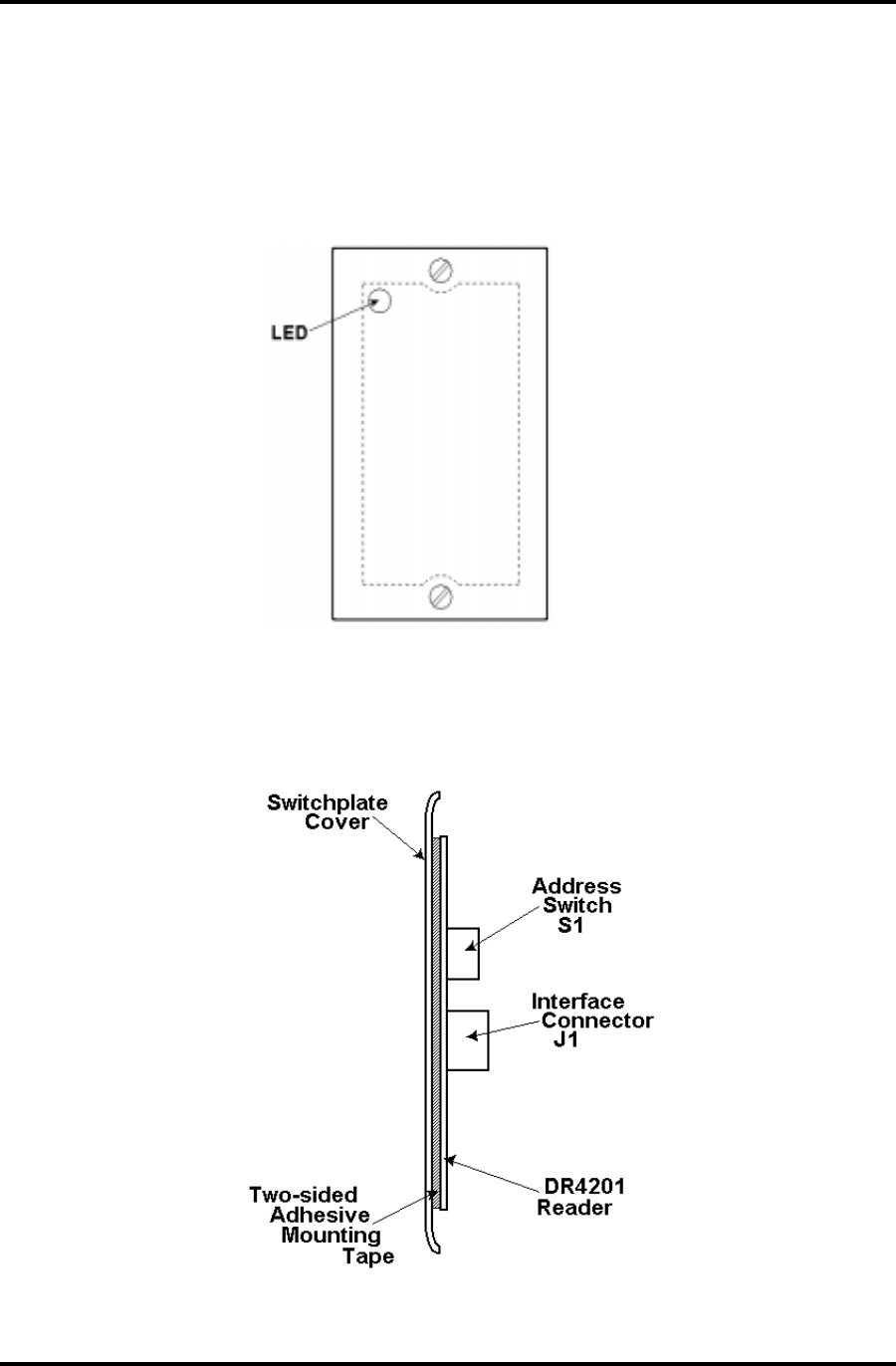
MOUNTING LOCATION (DR4201 READER)
The DR 4201 reader is designed to be mounted in a single-gang switch-plate receptacle, attached
to the back of a single-gang switch plate cover, as shown in figures 6 and 7, below.
Figure 6: DR4201 Front View (Mounted)
(The DR 4201 reader'sLED mode indicator is visible through the plastic cover in the upper left corner.)
Figure 7: DR4201 Side View (Mounted)
DigiReader Series
14 P/N 6600025, REV. BX
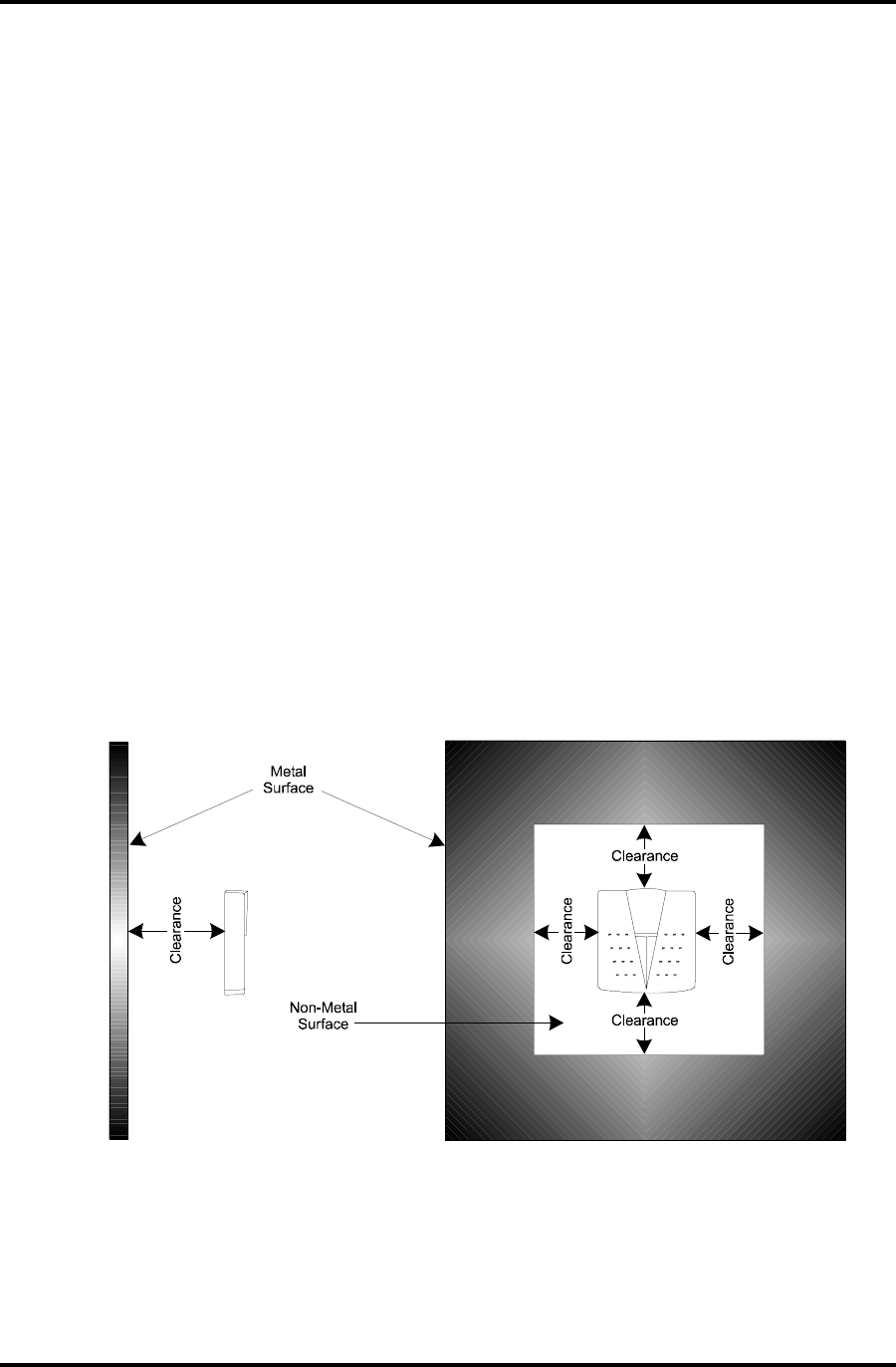
MOUNTING LOCATION (OTHER READERS)
Use care when choosing the installation site. To avoid possible external sources of RF interference,
do not locate the unit near motors, pumps, generators, DC-AC converters, AC switching relays, light
dimmers, or any other devices that emit an electronic radar frequency. Do not locate the unit within
10 feet (3 m) of a computer terminal.
The DR4203 and DR4204 units are the only two readers that are specifically designed to be mounted
on metal. Metal in the vicinity of any of the other devices can reduce the read range. In general,
as the amount of metal in close proximity to the device increases, the reliable maximum read range
decreases. For optimum operation, ensure that DigiReader has a minimum of 6 inches (15 cm)
clearance at the rear and surrounding sides, as shown in Figure 4. Never cover the front of the
DigiReader with any type of metal.
Use the method appropriate to the mounting surface material; if required, use sealing compound to
maintain water-resistance.
Figure 8: Mounting For Optimum Read Range

DigiReader Series
P/N 6600025, REV. BX 15
TESTING THE DIGIREADER LOCATION
If RF interference is suspected at a particular location, check the site prior to mounting the
DigiReader. A DigiReader may respond in one of two ways in the presence of RF interference:
The unit may beep and the LED illuminate with no access credential present.
Credential reads may be inaccurate or slow.
Use the following procedure to identify a location and position for DigiReader to minimize
interference.
1. Set the DigiReader address switches SW1 and SW2 to FF (test mode).
Connect only the wires which provide power.
Hold the DigiReader against the installation surface.
Without presenting a credential to the reader, listen for beeps indicating RF interference.
(Make sure you do not have a credential in your pocket or elsewhere, where it might be
detected.)
The greater the number of beeps, the noisier the readers environment.
2. Once a quiet (free of RF noise) location has been identified, connect the DATA A and DATA B
wires.
Set switches SW1 and SW2 to the correct address. The Controller must also be
connected to the S-Net and set up to read credentials.
Present a valid credential to the unit.
Verify that the credential can be read from the expected distance.
3. The DigiReader may again be moved to optimize the read-range.
If trouble persists, verify S-Net wiring and grounding.
Repeat steps 1 and 2 as necessary to identify the optimum installation location.
DigiReader Series
16 P/N 6600025, REV. BX
GENERAL INSTALLATION
See the procedures for the reader model and installation type below for additional instructions.
Cable Preparation:
1. Route the data and power cable to the DigiReader location and prepare the cable for attachment
to the DigiReader.
2. Remove two inches of the plastic jacket and the shielding foil from the cable.
3. Strip each wire back 1/4" for splicing to the DigiReader.
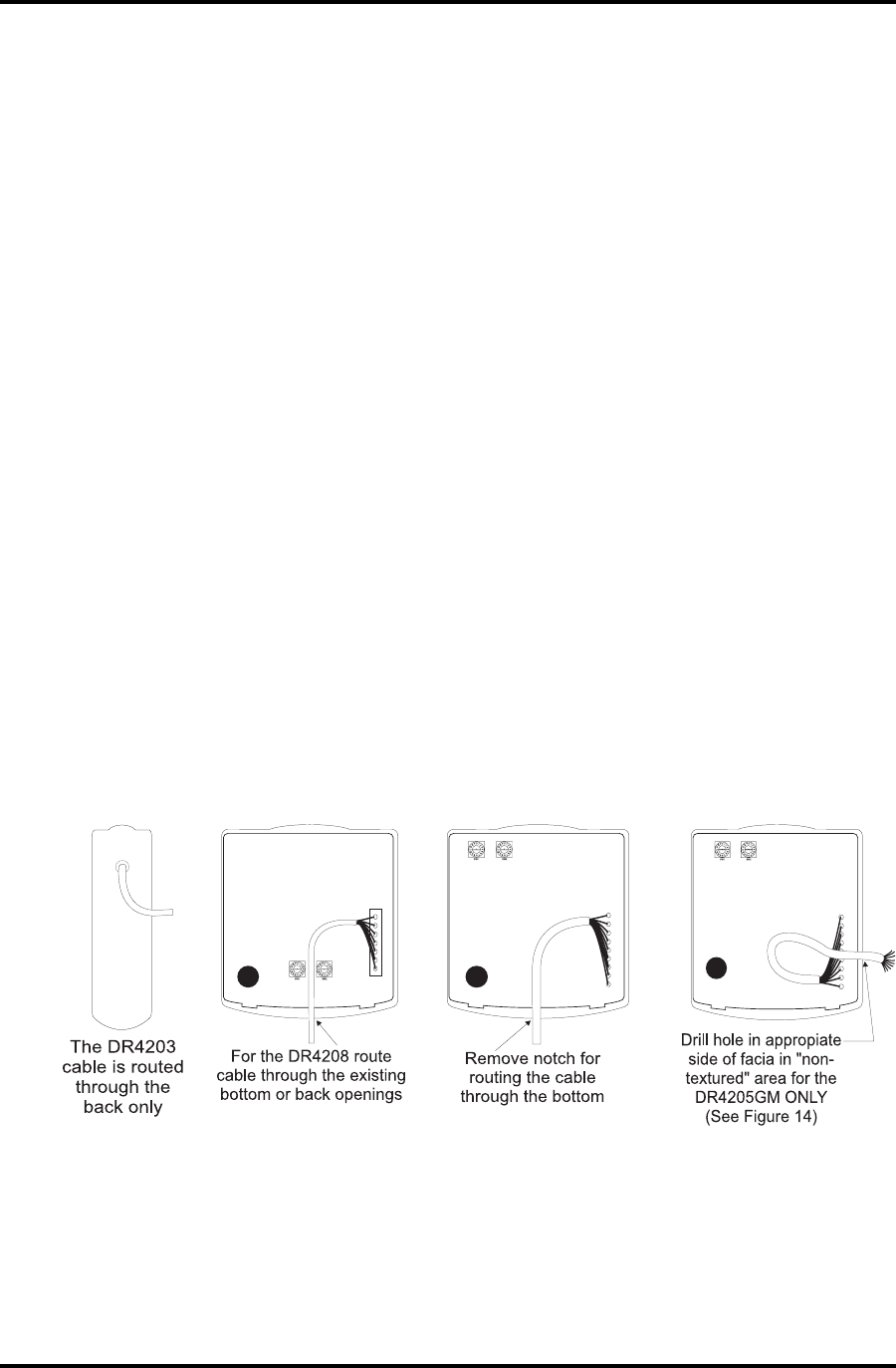
DR4203, DR4205 Series and DR4208 Installation:
1. S-Net cable on DigiReader may be routed from the back, bottom or the side of the DigiReader.
The reader is pre-configured for cable installation through the back mounting plate.
Note: S-Net cable is routed through the side on DR4205GM Reader only. (See Figures 9 and
14, below).
2. For readers other than DR 4205GM or DR 4203, remove the plastic notch from the bottom of
the cover. A rattail file may be used to enlarge the opening (Figure 9).
Figure 9: Cable Routing Configurations
Splice the DigiReader interface cable to the controller wiring run according to Table 3. If the
DigiReader is the last S-Net device on the S-Net cable run, install the termination jumper as
directed on page 5, 120 OHM TERMINATION JUMPER.
Set the address switch, as required.
DigiReader Series
P/N 6600025, REV. BX 17
DR4226 AND DR4238 INSTALLATION
1. Route the data and power cable to the DigiReader location and prepare the cable for attachment
to the DigiReader.
2. Remove two inches of the plastic jacket and the shielding foil from the cable.
3. Strip the wire back 1/4" for insertion into a crimp ring. Tin the stripped and ground wire ends.
4. Slip the Teflon tubing over the shield wire.
5. Use crimp tool to attach the crimp rings to each wire.
6. Make the five connections from the cable to the back of a DR4226 or DR 4238 reader using the
panhead screws. If the DigiReader is the last device on the S-Net run, install the termination
resistor between the Data A and Data B connections.
Table 9: DR4208 / DR4226 / DR4238 Wire Connections
7. Set the address switch, as required. The address switches on the DR4208 are on the inside
of the unit.
Figure 10: DR4226 / DR4238 Address Switch
DigiReader Series
18 P/N 6600025, REV. BX
WALL MOUNTING WITH SCREWS
After completing all connections to the DigiReader, weatherize the cable connections by
sealing the cable passage with a nonconductive silicone sealant.
Verify the correct address switch settings for proper operation and configuration.
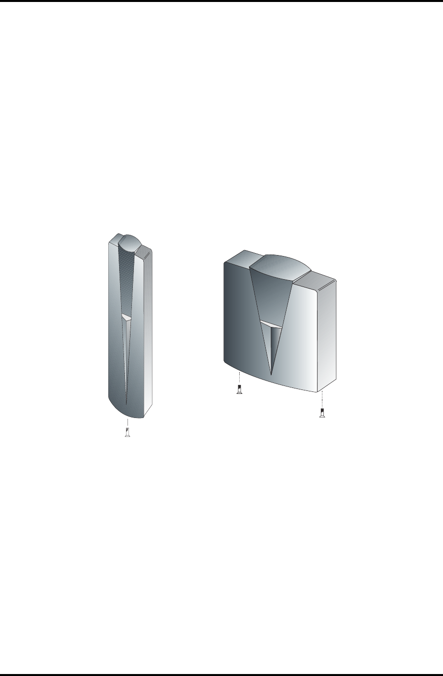
DR4203 and DR4205 Series
Mount the reader base to the wall. Use the four WSE-supplied, 1 1/4" Flathead, #6-32 thread
screws or other means appropriate to the wall composition.
Put the DigiReader cover in place and secure with the two self-captive screws from the bottom.
Figure 11: Securing DR4203 and DR4205 Series Cover
DR 4203
DR 4205
DigiReader Series
P/N 6600025, REV. BX 19
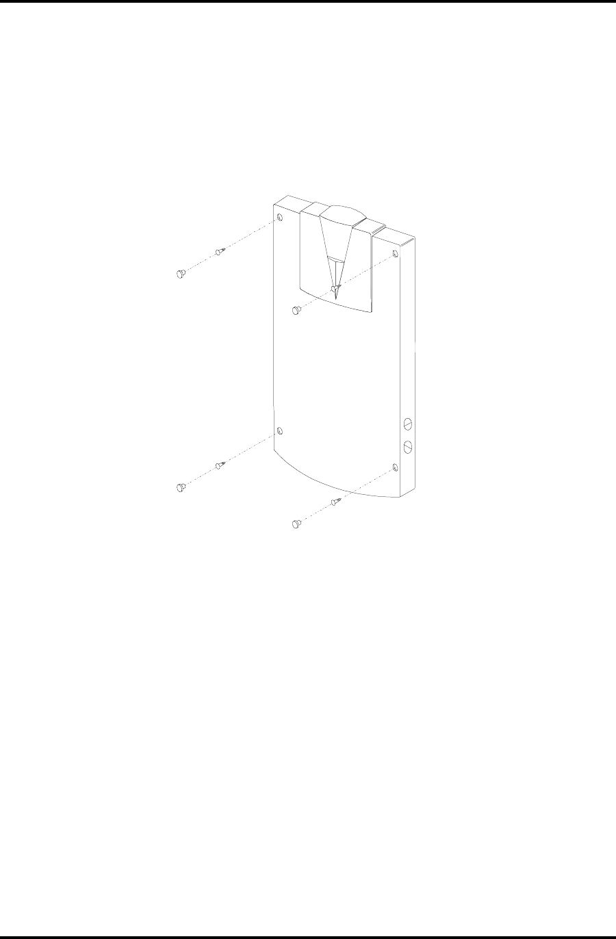
DR4226 and DR4238
Mount the reader to the wall using the four WSE-supplied, 1 1/4" flathead, #6-32 thread screws
or other means appropriate to the wall composition.
Install the four rubber caps to cover the screw heads on the face of the reader.
Figure 12: Mounting DR4226 and DR4238
DigiReader Series
20 P/N 6600025, REV. BX
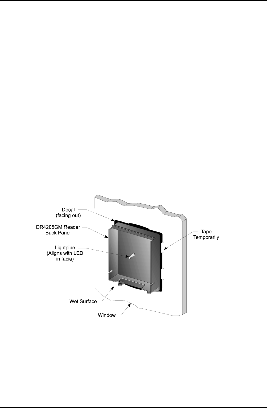
WINDOW MOUNTING DR4205GM
This type of mounting is necessary for DR4205GM unit.
1. Clean the window with glass cleaner or isopropyl alcohol and dry thoroughly.
2. Spray or wipe the window with slightly soapy water.
3. While the window is still wet, peel off the paper backing of the decal and press against the wet
section of the window and move around to release any air bubbles to assure maximum contact
with the window. Wipe dry any extra water coming out from the sides. See Figure 13.
4. Once the reader and decal are in place, it may be necessary to temporarily tape the reader to
the window while the adhesive sets. It should take approximately 10 minutes.
Figure 13: Placement of Decal and Reader onto Glass
DigiReader Series
P/N 6600025, REV. BX 21
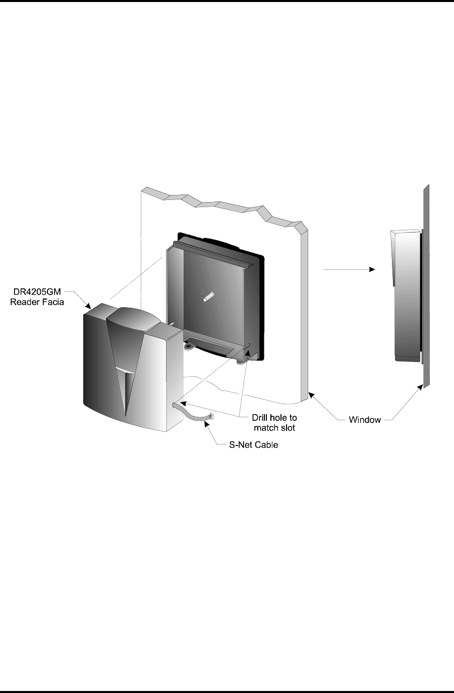
5. While the adhesive is setting, follow the general installation instructions on routing the cable
through the side channel and addressing the unit. After determining which side the cable will
be routed through, drill a hole in that side of the front facia to match the pre-drilled slots in the
back panel of the reader.
Note: To find exact hole location for drilling, look for a circle of smooth area on the side of the
facia, where there is an absence of texture in the lexan material. Reference page 16 for cabling
instructions. Also see Figure 14 below.
6. Secure the cover as shown in Figure 14.
Figure 14: Routing the Cable and Attaching the Facia
7. After the reader is securely set to the window, remove any masking tape used and clean the
window surrounding the reader.

DigiReader Series
22 P/N 6600025, REV. BX
CONTACTING WSE
Telephone: 1-800-227-1667
Monday through Friday
6:00am - 6:00pm (PST)
E-mail: WSEHelp@wse.com
Web Site: http://www.wse.com

DigiReader Series
P/N 6600025, REV. BX 23
Name of Manual: DigiReader Series: Installation and Operation Manual
Part Number: P/N 6600025 Revision: B
Organization: ________________________________________________________________
________________________________________________________________
Address: ________________________________________________________________
________________________________________________________________
________________________________________________________________
________________________________________________________________
OtherEquipment Ordered
With Your
DigiReader(s):
Evaluation of Manual:
POOR FAIR ADEQUATE GOOD EXCELLENT
Organization: 12345NA
Content: 12345NA
Style: 12345NA
Thoroughness: 12345NA
Clarity (Words): 12345NA
Clarity (Figures): 12345NA
Clarity (Tables): 12345NA
Were you able / was your integrator able to set
up your DigiReader(s) by using this manual? Y N NA
and/or Did you have to call Customer Service for help on one
or more issues? Y N NA
What additional aid(s) did you use to bring up your equipment?
________________________________________________________________
________________________________________________________________
Other Comments
(Positive): ________________________________________________________________
________________________________________________________________
________________________________________________________________
________________________________________________________________
Other Comments
(Negative): ________________________________________________________________
________________________________________________________________
________________________________________________________________
________________________________________________________________
Please tear off this sheet, fill it out, and return it within 3 months of system installation.

DigiReader Series
24 P/N 6600025, REV. BX