Honeywell orporated DR4208K Access Control Proximity Reader User Manual 6 28 02
Honeywell International Incorporated Access Control Proximity Reader 6 28 02
UserManual.wiki
>
Honeywell orporated
>
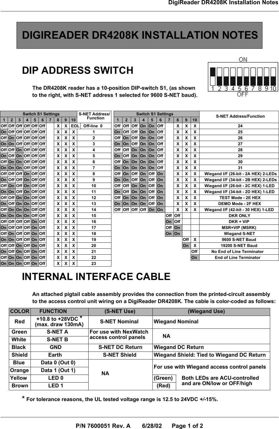
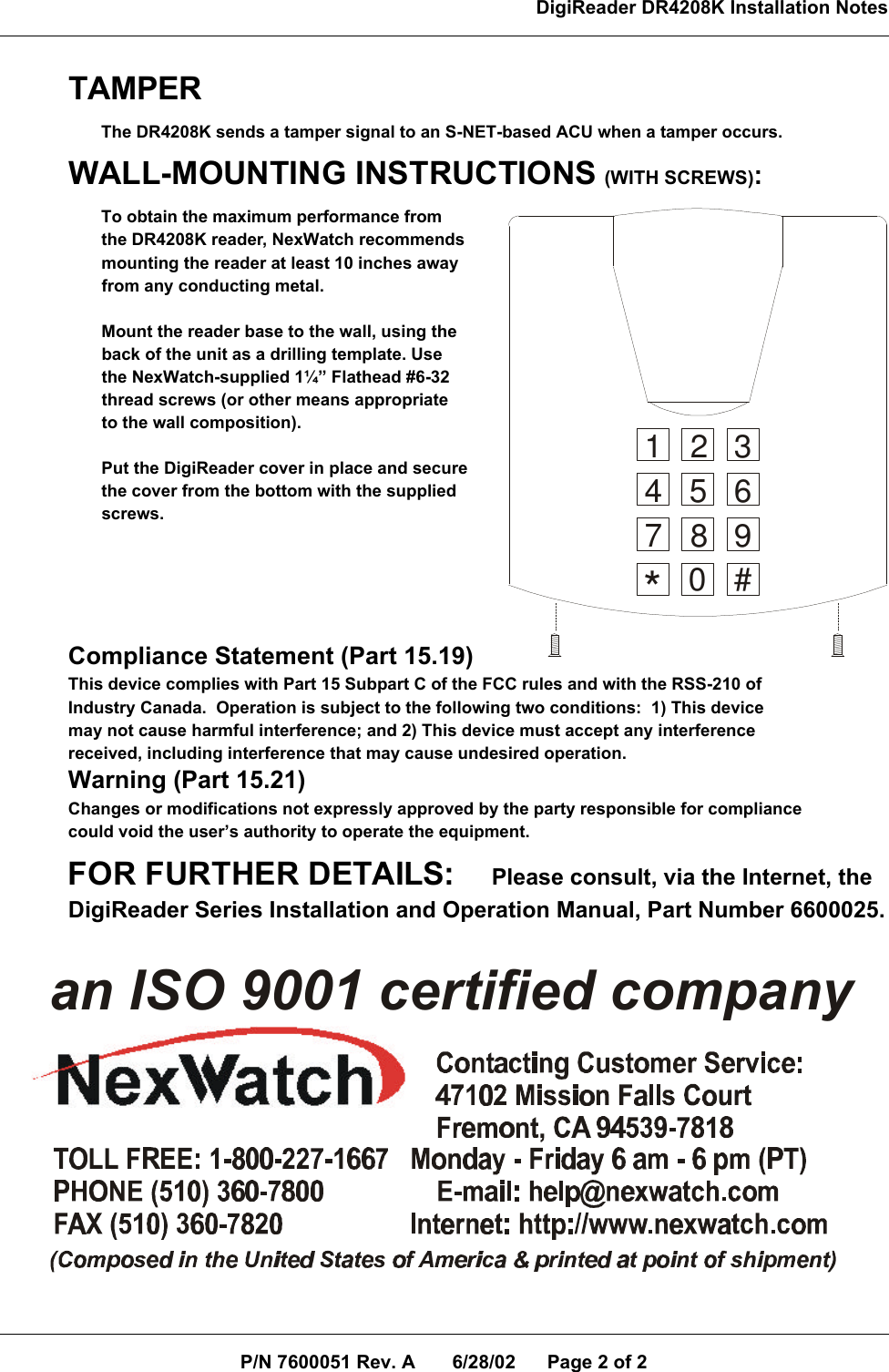
DR4208K User Manual
Users Manual
Navigation menu
Upload a User Manual
Namespaces
Wiki Guide
HTML
PDF
Info
Views
User Manual
Discussion / Help
Navigation