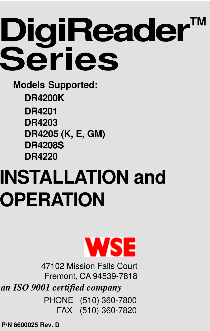
Honeywell orporated DR4220 Proximity Reader User Manual Frontmtr

Honeywell International Incorporated Proximity Reader Frontmtr

Contents

Manual

Models Supported:DR4200KDR4201DR4203DR4205 (K, E, GM)DR4208SDR4220DigiReader™SeriesP/N 6600025 Rev. DPHONE   (510) 360-7800FAX   (510) 360-7820an ISO 9001 certified companyINSTALLATION andOPERATION47102 Mission Falls CourtFremont, CA 94539-7818
  ii P/N 6600025, Rev. DDigiReader Series© Copyright 2000 WSEAll rights reserved.  Printed in the United States of America.NexSentry™, QuadraKey™, NexKey™, KeyMate™, 2Smart™, and DigiReader™ are trademarks ofWSE.ProProx™, ISOProx™, DuoProx™, and Corporate 1000™ are trademarks of HID Corporation.Teflon™ is a trademark of the DuPont Corporation.Printed in the U. S. A.
P/N 6600025, Rev. D                                                                                                              iiiDigiReader Series  WSELIMITED WARRANTYWSE  warrants to the original user the equipment manufactured by WSE as described herein to be freefrom defects in material and workmanship for a period of one year from the date of purchase by such useror fifteen (15) months from the date of shipment from the factory, whichever is sooner (command key/magnetic stripe card warranties differ, see below*), provided:I WSE has been notified within such period by return of any alleged defective equipment, free andclear of any liens and encumbrances to WSE or its authorized dealer at the address specified,transportation prepaid;II the equipment has not been abused, misused or improperly maintained and/or repaired duringsuch period;III such defect has not been caused by ordinary wear and tear;IV such defect is not a result of voltage surges/brownouts, lightning, water damage/flooding, fire,explosion, earthquakes, tornadoes, acts of aggression/war, or similar phenomena;V accessories used as integral to WSE systems have been approved by WSE (e.g., coaxialcables, batteries, etc.);VI the equipment has been installed, the installation supervised or installation tested by anauthorized WSE dealer.WSE shall, at its option, either repair or replace, free of charge, the equipment found, upon WSE’sinspection to be so defective, or if agreed upon, to refund the purchase price, less a reasonable allowancefor depreciation, in exchange for the equipment.WSE MAKES NO OTHER WARRANTY, AND ALL IMPLIED WARRANTIES INCLUDING ANY WARRANTYOF MERCHANTABILITY OR FITNESS FOR A PARTICULAR PURPOSE ARE LIMITED TO THEDURATION OF THE EXPRESSED WARRANTY AS SET FORTH ABOVE.WSE’S MAXIMUM LIABILITY HEREUNDER IS LIMITED TO THE PURCHASE PRICE OF THE EQUIPMENT.IN NO EVENT SHALL WSE BE LIABLE FOR ANY CONSEQUENTIAL, INDIRECT, INCIDENTAL ORSPECIAL DAMAGES OF ANY NATURE ARISING FROM THE SALE OR USE OF THE EQUIPMENT.Some states do not allow limitations on incidental or consequential damages or on how long an impliedwarranty lasts, so the above limitations may not apply.  This warranty gives specific legal rights; however,other rights which vary from state to state, may pertain.Digital command key and magnetic stripe card warranties vary, according to the particular card used.  Seethe product literature.The information in this manual is believed to be accurate and reliable.  However, WSE assumes noresponsibility for any errors that may appear.  Possession of this manual does not imply the granting oflicenses to make or sell equipment or software constructed according to descriptions provided.
  iv P/N 6600025, Rev. DDigiReader SeriesFEDERAL COMMUNICATIONS COMMISSION RADIOFREQUENCY INTERFERENCE STATEMENTThis device complies with part 15, sub-part C of the FCC Rules. Operation is subject to the followingtwo conditions:1. This device may not cause harmful interference; and2. This device must accept any interference received, including interference that may causeundesired operation.NOTE:Regulatory labels are not attached at the factory. They are included in the ship-kit withthe PC-board and must be applied visibly to the enclosure (if purchased), or (if not)to the back of the PC-board.
P/N 6600025, Rev. D                                                                                                              vDigiReader Series  WSETable of ContentsCOPYRIGHT AND TRADEMARK INFORMATION .............................................................................................. iiLIMITED WARRANTY ........................................................................................................................... iiiFEDERAL COMMUNICATIONS COMMISSION RADIO FREQUENCY INTERFERENCE STATEMENT ................................. ivINTRODUCTION ....................................................................................................................................1GENERAL SPECIFICATIONS ....................................................................................................................2DR 4205 SERIES SPECIFICATIONS .........................................................................................................3BASIC OPERATION ...............................................................................................................................4LED (AND BEEPER) OPERATION ..................................................................................................4     LED (AND BEEPER) (S-NET OPERATION) ...........................................................................................4     LED (WIEGAND OPERATION) ...........................................................................................................6120-OHM TERMINATION JUMPER (INTERNAL/EXTERNAL) ..............................................................................7INTERNAL INTERFACE CABLE FOR DR4200K, DR4201, DR4203, DR4205 (ALL MODELS), DR4208S     AND DR4220 ...............................................................................................................................7RECOMMENDED S-NET CABLE ...............................................................................................................8DIGIREADER ADDRESS SWITCHES ..........................................................................................................8     ROTARY ADDRESS SWITCHES FOR DR4200K, DR4203, AND DR4205 (ALL MODELS) ..............................8     DIP ADDRESS SWITCH FOR DR4201, DR4208S, AND DR4220 ........................................................9SPECIAL FEATURES OF THE DR4201 AND DR4208S DIGIREADERS ........................................................... 11     READER OPERATION (S-NET MODE) ................................................................................................ 11     READER OPERATION (26-BIT AND 34-BIT WIEGAND MODE) .................................................................12DR4205K SPECIAL OPERATING FEATURE ..............................................................................................13     NORMAL MODE ...........................................................................................................................13     KP-CREDENTIAL MODE ................................................................................................................14TAMPER SIGNAL (S-NET ONLY) ............................................................................................................15S-NET CONNECTIONS ........................................................................................................................15WIEGAND CONNECTIONS ....................................................................................................................16MOUNTING LOCATION .........................................................................................................................17     SPECIAL MOUNTING LOCATION: DR4201 READER .............................................................................18TESTING THE DIGIREADER LOCATION ....................................................................................................20GENERAL INSTALLATION ......................................................................................................................21     CABLE PREPARATION ....................................................................................................................21     DR4200K, DR4203, DR4205 SERIES, DR4208S AND DR4220 INSTALLATION ..................................21WALL MOUNTING WITH SCREWS .........................................................................................................23     DR4203, DR4205 SERIES, DR4208S, AND DR4220.....................................................................23WINDOW MOUNTING THE GLASS-MOUNTED UNITS .................................................................................. 24TROUBLESHOOTING ...........................................................................................................................26     TUNE COMMAND (FOR THE NEXSENTRY STAR AND 4100-SERIES CONTROLLERS) ...................................26CONTACTING WSE TECHNICAL SERVICE ...............................................................................................27POSTAGE-PAID CUSTOMER COMMENT .............................................................................................. 29, 30
  vi P/N 6600025, Rev. DDigiReader SeriesTables1DIGITAL READER SPECIFICATIONS ..............................................................................................21A DR4205 SERIES SPECIFICATION ..............................................................................................32 DR4205K/DR4200K SYSTEM LED/BEEPER BEHAVIOR, (BOTH DIGITAL READER AND     KEYPAD CAPABILITY ENABLED) .............................................................................................52A DIGIREADER SYSTEM LED/BEEPER BEHAVIOR, (ONLY READER CAPABILITY ENABLED) .........................62B DR4205K/DR4200K DYSTEM LED/BEEPER BEHAVIOR, WITH ONLY DIGITAL KEYPAD     ENABLED ........................................................................................................................63TERMINATION JUMPERS ...........................................................................................................74INTERNAL INTERFACE CABLE FOR DR4200K, DR4201, DR4203, ALL MODELS OF DR4205,     DR4208S, AND DR4220 .................................................................................................75RECOMMENDED S-NET CABLE ..................................................................................................86VALID SWITCH SETTINGS FOR SWITCHES 1 AND 2.......................................................................97 DR4201, DR4208S, AND DR4220 ADDRESS DIP-SWITCH SELECTIONS ....................................108 DR4205K NORMAL MODE SWITCH SETTINGS, SWITCHES SW1 AND SW2 ..................................139 DR4205K KP-CREDENTIAL MODE SWITCH SETTINGS, SWITCHES SW1 AND SW2 .......................1410 TAMPER SWITCH(ES) ............................................................................................................1511 RECOMMENDED WIEGAND CABLE GAUGE .................................................................................16Figures1THE DIFFERENT DIGIREADER MODELS (NOT TO SCALE) ...............................................................12 LED LOCATIONS FOR THE DIFFERENT DIGIREADER MODELS .........................................................53ADDRESS SWITCHES FOR DR4200K, DR4203, AND DR4205 (ALL MODELS) .................................84ADDRESS (DIP) SWITCH FOR DR4201/4208S/4220 SHOWING READER ADDRESS 1 SELECTED .......95 S-NET WIRING ...................................................................................................................156TYPICAL WIEGAND CONNECTION .............................................................................................177MOUNTING (DR4205 AND DR4208S) FOR OPTIMUM READ RANGE WITH METAL IN THE VICINITY ....188EUROPEAN AND US GANG BOX MOUNTING HOLES INDICATED ......................................................189 DR4201 MOUNTING HOLES INDICATED ...................................................................................1910 DR4201 MOUNTING TEMPLATE (TO SCALE .PDF FILE ONLY)........................................................1911 CABLE ROUTING CONFIGURATIONS ..........................................................................................2212 SECURING THE DR4203, DR4205 SERIES, DR4208S AND DR4220 COVERS ............................2313 DR4205GM: PLACEMENT OF DECAL AND READER ONTO GLASS ..................................................2414 DR4205GM: ROUTING THE CABLE AND ATTACHING THE FACIA ....................................................25
DigiReader SeriesP/N 6600025, REV. D                                                                                                              1INTRODUCTIONThe DigiReader Series is a family of Digital Proximity Readers (DigiReaders).   (Graphic represen-tations of the DigiReader Series —not to scale— are shown in figure 1, below, and figure 2, on page5.)  DigiReaders are bi-directional security devices that read digital credentials, (from either side ofthe sensor), at ranges from 1 to 20 inches (2½ to 51 cm), depending upon the model and theenvironmental conditions.  DigiReaders are used with the NexSentry 4100, 4102, 4104, Star I andStar II (4100 Series), SE818SC and SE422 Access Control Units (ACUs), with the ACUs eitheroperating as stand-alone devices or operating in conjunction with a StarGaze, a NexSentry Manager(NSM), a NexSentry Command Center (NSCC), (an SE6000), or an SE5850, WSE Access ControlHost System.  Connection between a DigiReader and an ACU is over the WSE proprietary S-Netinterface or over a Wiegand interface to a Wiegand ACU.  (The Wiegand data can be either 26- or34-bit Wiegand standard.)  (Also included in the DigiReader Series is a keypad-only reader, theDR4200K, which is the only family member available with the analog 818SX ACU.)CAUTION 1.   Read this manual carefully before attempting to wire in place a DigiReader.The warranty is void if damage occurs to the unit as a result of incorrectwiring.CAUTION 2.   The information in this manual is not intended to conflict with the building codes,electrical codes, fire codes, or safety codes required for any given installation.In all cases, the prevailing building codes must take precedence.DR4201 DR4203 DR4205/DR4208SDR4205K/DR4200KDR4220Figure 1:  The Different DigiReader Models (Not to Scale)
DigiReader Series2                                                                                                                  P/N 6600025, REV. DGENERAL SPECIFICATIONSTable 1: Digital Reader Specifications*See Table 1A  for details on DR4205 ReadersK0024RD 1024RD 3024RD 5024RD *seireS S8024RD 0224RDnoitpircseD K5024RD ,ekilA-kooL ylnOdraobyeK/tsoctsewoL redaertsellams 'hctiwsthgil'rof sgnitnuomepytlatigiD ytimixorp roodrofredaer snoillumtnereffiD dnasngised sgnitnuom seiresnihtiw *ytimixorplatigiD htiwredaer daerdesaercni egnarytimixorplatigiD htiwredaer daermumixam egnar).hcnI(snoisnemiD3.1x0.5x0.57.0x8.4x3.32.1x5.7x8.1* 72.1x47.5x3.50.1x4.21x3.41).mC(snoisnemiD2.3x7.21x7.218.1x2.21x4.80.3x0.91x5.4* 2.3x6.41x5.315.2x5.13x3.63ycneuqerFtimsnarTANnoitarepoxelpudlluf,zHk231ycneuqerFrevieceRANzHk66revieceR noitaludomeD ANlangis)KSP(yeKtfihS-esahPelcyCdaeRdraCANcesm001:ecruoSrewoP teN-S Am08nahtssel,CDV82+ot61+ 82+ot21+ Am051<,CDV ,CDV82+ot31+ lanimonpmA6.0:ecruoSrewoP dnageiW Am08nahtssel,CDV82+ot61+ 82+ot21+ Am051<,CDVliatgiPdnageiW rotcennoC seY*seY-S8024RD )oN-8024RD( seY-0224RDUCAotecafretnI )ytilibapaceriw9( ,RO,dnageiWeriw-5tib-43/62+)mmocteN-S,584-SRrofdleihs+GWA22(riapdetsiwtlaud=liatgiperiw-9 tinUF/IdnageiWSNhtiw,seireS0014SNrof-dnageiWeriw-5etarapes+584-SReriw-4,)noitangisedW(UCAotecafretnI )ytilibapaceriw4( /CS818/XX14( )sUCA224/XS818 -S,584-SRrofdedleihs,GWA22(riapdetsiwtlauD 224ESroCS818otlAroXX14SNrof-)mmocteNnoitapissiDrewoPsttaw2nahtsseL w71nahtsseLsrellortnoC .XS818-ylnoK0024RD:ETON.224ES,CS818otlA,seireS0014dnaIratSyrtneSxeNsrotacidnIelbammargorp,)der-wolley-neerg(roloc-irtelgniSnoitcetorPrepmaTseYytidimuH %09ot%01 gnisnednoc-non %09ot%01 gnisnednoc-non %09ot%01 gnisnednoc-non *%09ot%5 gnisnednoc-non %09ot%01 gnisnednoc-non(erutarepmeT)F°051ot13-*051ot13-(erutarepmeT)C°66ot53-*66ot53-tnemnorivnEroodtuO/roodnIroodtuO/roodnIroodtuO/roodnI* esuroodtuOdnaroodnI).sbL(thgieW57.03.01<* 57.3<)smargK(thgieW43.211.054.0<*86.3.2<tnailpmocADA :edulcnisseccadelbasidgnisaerofserutaeflaicepS;seY sutatssseccaetacidniotsrotacidnilausivdnaelbidua,sseccaeerf-sdnahegnaRdaeR.xaM K0024RD 1024RD 3024RD 5024RD S8024RD 0224RD)stinU(-).nI().mC().nI().mC().nI().mC().nI().mC().nI().mC(yeKardauQAN5.1ot8.3ot3ot6.7ot4ot01ot6ot51ot61ot04ottramS2AN5.1ot8.3ot3ot6.7ot4ot01ot6ot51ot61ot04otyeKxeNAN5.1ot8.3ot3ot6.7ot4ot01ot6ot51ot61ot04otetaMyeKAN1ot5.2ot1ot5.2ot2ot5ot3ot8ot41ot53ot.noitallatsnifotnemnorivnelacisyhpnognidnepedyravyamegnardaermumixaM
DigiReader SeriesP/N 6600025, REV. D                                                                                                              3DR 4205 SERIES SPECIFICATIONSTable 1A: DR4205 Series Specifications5024RD E5024RD MG5024RD K5024RDnoitpircseDredaerytimixorplatigiD redaerytimixorplatigiD rofdetaocyllamrofnoc esulanretxeredaerytimixorplatigiD gniebfoytilibapachtiw detnuomssalgredaerytimixorplatigiD detargetnihtiw rofdapyekfoorpretaw esuroodtuodnaroodniytilibapaCdnageiW :Wahtiwdetangisedsiroliatgiperiw-9sahledomfI MGW5024RDEW5024RDW5024RDrellortnocotecafretnI )ytilibapaceriw9(dna)noitacinummocteN-S,584-SRrofdedleihs,GWA22(riapdetsiwtlaudgniniatnocliatgiperiw-9 dnageiWeriw-5etarapes+584-SReriw-4,)noitangisedW(,RO,dnageiWeriw-5tib-43ro-62 tinUecafretnIdnageiWyrtneSxeNhtiw,seireS0014yrtneSxeNrof-rellortnocotecafretnI )ytilibapaceriw4( )noitacinummocteN-S,584-SRrofdedleihs,GWA22(riapdetsiwtlauD 224ESroCS818otlAro,seireS0014yrtneSxeNrof-snoisnemiD )mc2.3x6.41x5.31("72.1x"47.5x"3.5ycneuqerFtimsnarTnoitarepoxelpudlluf,zhK041ycneuqerFrevieceRzHk07noitaludomeDrevieceRlangis)KSP(yeKtfihS-esahPelcyCdaeRdraCcesm001teN-S:ecruoSrewoP Am08nahtssel,CDV82+ot61+dnageiW:ecruoSrewoPnoitapissiDrewoPsttaw2nahtsseLsrotacidnIelbammargorp,roloc-irtelgniSnoitcetorPrepmaTseYytidimuH %09ot%01 gnisnednoc %001ot%5 gnisnednoc %09ot%01 gnisnednoc %001ot%5 gnisnednoc(erutarepmeT)F°021ot23051ot13-021ot23051ot13-erutarepmeT)C°(94ot066ot53-94ot066ot53-tnemnorivnEylnoesuroodnI dnadezirehtaeW roffoorp-hsalps esuroodtuo ylnoesuroodnI dnadezirehtaeW roffoorp-hsalps esuroodtuo)secnuO(thgieW51429151)smarG(thgieW024276235024tnailpmocADA :edulcnisseccadelbasidgnisaerofserutaeflaicepS;seY sutatssseccaetacidniotsrotacidnilausivdnaelbidua,sseccaeerf-sdnahegnaRdaeRmumixaM sledoM5024RDllA)stinU()sehcnI()sretemitneC(yeKardauQ4otpu01otputramS24otpu01otpuyeKxeN4otpu01otpuetaMyeK2otpu5otpu
DigiReader Series4                                                                                                                  P/N 6600025, REV. DBASIC OPERATIONDigiReaders emit a low-level 140-kHz field.  When a digital credential (card, KeyMate™, DuraTag™,etc.) is placed in this field, a digital chip embedded in the credential uses the field’s energy foractivation.  Once activated, the credential responds by broadcasting a 70-kHz signal, modulatedwith a credential-specific code sequence, back to the reader. The reader receives this signal andconverts it to a digital code which is then sent to the ACU, (the Controller).  The Controller identifiesthe digital credential according to its code and makes either an access granted or an access denieddecision, based on credential information stored in the Controller's database or the host system'sdatabase.The DR4205K has a keypad on the face of the DigiReader. The keypad is used to enter the user’sPersonal Identification Number (PIN). The DR4205K keypad version can be configured for credential-only use, or keypad-only use, or both, from the ACU DOOR Command. If the S-Net Reader Typeentry is set to DKR, the credential use will be activated for that door; set to NONE, the credentialuse for that door will be de-activated; (–  this is true for all DigiReaders except the DR4200K). Forthe same door/reader combination, if the VIP Enable is set to Yes or No, the keypad portion will beactivated or de-activated, respectively.The DR4200K is a keypad-only reader look-alike of the DR4205K, activated from the ACU DOORCommand by setting VIP Enable (for that door) to Yes.LED (AND BEEPER) OPERATIONLED (AND BEEPER) (S-NET OPERATION)All DigiReaders have a single three-color (red-amber-green) LED controlled by the Access ControlUnit (ACU) to which the DigiReader is attached.  Figure 2 shows the location of the LED on eachof the DigiReader models.With the DigiReader on line to an ACU and with power applied, (the ready state), the DigiReader'sLED will be a constant red.  When a DigiReader is configured to read digital credentials only (withno keypad part of the DR4205K or VIP2 or DR4200K activated for the same door), a valid credentialwill produce a momentary amber LED, followed by a green LED for the door unlock time or until thedoor is closed following the credential-holder's access; (the LED will then return to the constant red).With a keypad also activated, the amber LED will continue until either both the valid digital credentialand valid PIN, in either order, have been read/entered, producing the green unlock time LED, or untilthe PIN grace period has been exceeded, producing the red LED.  With only the keypad activated,a valid PIN will produce the momentary amber, the unlock green and the return to the constant red.
DigiReader SeriesP/N 6600025, REV. D                                                                                                              5Figure 2:  LED Locations for the Different DigiReader ModelsNOTE: In each WSE security management system, the TUNE command (or its equivalent) is usedto specify LED and beeper behavior when a valid key is presented.eniL-nO eniL-ffO omeDsutatS DEL repeeB DEL repeeB DEL repeeBlaitnederCoN ottneSataD K0024oN,UCA yeKK5024ro desserPderydaetSffOderhsalF:elcyC ydaets,.ces4rof ,.ces4rofrebma .ces25rofffoffO ydaetS der ffOlaitnederCdilaV daeRlitnu,rebmaydaetS ecargroyrtneNIP dnedoirepelgniS peeb rebmahsalF ylsuounitnoc sdnoces2.0~ dracelihw tneserppeeB -nitnoc ylsuou ces8.0~ elihw drac tneserpydaetS &rebma 01~rof retfaces gnivomer dracpeeB yreve ces2~ elihw drac tneserpdilavnI laitnederC rofffoydaetS emitelbasidredaer elgniS peebNIPdilaV deretnENIPlitnuderydaetS ydaets,deretne daerdraclitnurebma dnedoirepecargrorofpeeB NIPhcae tigid deretnederhsalF:elcyC ydaets,.ces4rof ,.ces4rofrebma .ces25rofffo morfdegnahcnu( rodesserpyekon )detneserpdracpeeB rofecno yreve yek desserplitnudeR syek6 ,desserp neht rofrebma 01~ sdnocespeeB rofecno yreve yek desserp otpu( )6NIPdilavnI litnurebmaydaetS dnedoirepecarg peeB tigidhcae-yekdnaredaerlatigidhtob(,roivaheBrepeeB/DELmetsySK0024RD/K5024RD )roodemasnooslaredaeRigiDhtiw,K0024RDfi.....()delbaneytilibapacdap)gnimmargorpUCAybdenimreted,lortnocUCArednuroivahebDEL(Table 2:The complete operational characteristics (LED and beeper behavior) for a DigiReader with or withoutkeypad, or with the keypad only used, are shown, (respectively), in Tables 2, 2A and 2B, below.DR4201LEDDR4203LEDLEDDR4205K/DR4200KDR4205/4208S/4220LED
DigiReader Series6                                                                                                                  P/N 6600025, REV. DeniL-nO eniL-ffO omeDsutatS DEL repeeB DEL repeeB DEL repeeBroK0024oN yeKK5024 desserPderydaetSffOderhsalF:elcyC ydaets,.ces4rof ,.ces4rofrebma .ces25rofffoffO ydaetS der ffONIPdilaV deretnENIPlitnuderydaetS yratnemom,deretne neergydaets,rebma /elbasidredaerrof emitneporoodrofpeeB NIPhcae tigid deretnederhsalF:elcyC ydaets,.ces4rof ,.ces4rofrebma .ces25rofffo morfdegnahcnu( rodesserpyekon )detneserpdracpeeB hcaerof tigidNIP deretnelitnudeR syek6 ,desserp neht rofrebma 01~ sdnocespeeB rofecno yekyreve desserp )6otpu(NIPdilavnI rebmaydaetS hcaepeeB tigiddelbanedapyeklatigidylnohtiw,roivaheBrepeeB/DELmetsySK0024RD/K5024RD)gnimmargorpUCAybdenimreted,lortnocUCArednuroivahebDEL(eniL-nO eniL-ffO omeDsutatS DEL -peeB re DEL repeeB DEL repeeBlaitnederCoN ottneSataD UCA derydaetSffOderhsalF:elcyC ydaets,.ces4rof ,.ces4rofrebma .ces25rofffoffO ydaetS der ffOdilaV laitnederC daeRneergydaetS skcolnuroodsapeeB 5~ cesrebmahsalF ylsuounitnoc sdnoces2.0~ dracelihw tneserppeeB ylsuounitnoc ces8.0~ dracelihw tneserpydaetS &rebma 01~rof retfaces gnivomer dracpeeB yreve ces2~ elihw drac tneserpdilavnI laitnederC rofffoydaetS emitelbasidredaer peeB ecno)delbaneytilibapacredaerylno(,roivaheBrepeeB/DELmetsySredaeRigiD)gnimmargorpUCAybdenimreted,lortnocUCArednuroivahebDEL(Table 2A:Table 2B:LED (WIEGAND OPERATION)The LED is controlled to be red or green by the level of the Wiegand LED control input.  This is afunction of the particular Wiegand unit.
DigiReader SeriesP/N 6600025, REV. D                                                                                                              7120-OHM TERMINATION JUMPER (INTERNAL/EXTERNAL)The jumper places 120 ohms of resistance between Data A and Data B for proper end-of-linetermination.  Install the jumper only if the DR4200 Series DigiReader is the last device on the cable.Table 3: Termination JumpersINTERNAL INTERFACE CABLE      (FOR DR4200K, DR4201,DR4203, DR4205--ALL MODELS, DR4208S * & DR4220)An attached pigtail cable assembly provides the connection from the printed-circuit assembly andkeypad to the access control unit wiring on all of the following DigiReader models: DR4200K,DR4201, DR4203, DR4205, DR4205E, GM, K and W, DR4208S ( - note the wider voltage range)and DR4220.  The cable is color coded as follows:Table 4: Internal Interface Cable for DR4200K, DR4201, DR4203,all models of DR4205, DR4208S, and DR4220redaeR repmuJnoitanimreT redaeR repmuJnoitanimreT*lanretnI noitacoL *lanretnI noitacoLK0024RDseY1W**5024RDseY1W1024RDseY1WS8024RDseY1W3024RDseY3W0224RDseY1W*sledom)TMS(ygolonhcettnuomecafrusnoelbaliavaylnorepmuJ W5024RDdnaK5024RD,MG5024RD,E5024RD,5024RD:sledomllA**ROLOC NOITCNUF )esUteN-S( )esUdnageiW(deR CDV82+ot61+ lanimoNteN-SlanimoNdnageiW*CDV82+ot21+neerGAteN-S ESWhtiwesuroF sseccateN-S slenaplortnoc ANetihWBteN-SkcalBnruteRCDnruteRCDteN-SnruteRCDdnageiWdleihSdleihSlangiSdleihSteN-SnruteRCDdnageiWotdeiT:dleihSdnageiWeulB)0tuO(0ataDANslenaplortnocsseccadnageiWhtiwesuroFegnarO)1tuO(1ataDwolleY0DEL)deR( dellortnocUCAerasDELhtoB hgih/FFOrowol/NOeradnanworB1DEL)neerG(
DigiReader Series8                                                                                                                  P/N 6600025, REV. DRECOMMENDED S-NET CABLEThe type of cable used for the S-Net will depend on the total length and the number of devicesconnected.  Table 5 lists WSE-recommended cables:Table 5: Recommended S-Net CableDIGIREADER ADDRESS SWITCHESRotary Address Switches for DR4200K, DR4203, and DR4205 (all models)Each DigiReader must have a unique address.  The DR4200K, DR4203, and DR4205 (all models)DigiReaders use two address switches S1 and S2, (as shown in Figure 3):Figure 3:  Address Switches for DR4200K, DR4203, and DR4205 (all models)• Switch SW1 is used to select the special reader modes of operation, (as shown in Table 6).SW1 is set to 0 (factory default setting) for S-Net operation and F for Wiegand operation.• Switch SW2 is used to set the Reader/Door address, and, with SW1 set to F, for additionaloptions, including (SW2 = A or B) the Wiegand number of bits.  SW2 has a factory defaultsetting of 1, but it may be set to any address from 1 to F (15).  A 16th DigiReader address isprovided by setting switch SW2 to 0 and switch SW1 to 8 (for Normal Mode), or C, D or E (forDR4205K PIN/Credential Mode - see below).ERUTCAFUNAM LACISYHP NOITPIRCSED EGUAG.tF0004<rewoPdnaataD elbaC&eriWtsewhtuoS yarG/971WS ataD:rotcudnoC2 rewoP:rotcudnoC2 GWA22 GWA61.tF005<rewoPdnaataD 2559nedleB 9601nedleB dedleihSriaP-2 GWA81 GWA61.tF005>ylnOataD1489nedleBdedleihSriaP-1GWA42.tF005>ylnOrewoP 1439nedleB 2431nedleB 3439nedleB rotcudnoC2 GWA81 GWA61 GWA41
DigiReader SeriesP/N 6600025, REV. D                                                                                                              9Valid addresses may be limited by the controller; (see the appropriate controller manual).When used with an SE422, addresses 01 and 02 should be assigned to nodes 13 (VIP2/DR4200K)and 15 (DKR), and 14 (VIP2/DR4200K) and 16 (DKR), respectively, see section 6 of the SE422Installation Manual (p/n 66108328001), under Entry (Door) programming, questions 14 and 15.Table 6:  Valid Switch Settings for Switches 1 and 2(* See DR4205K SPECIAL OPERATING FEATURE, page 11)(** See NORMAL MODE, page 11 or PIN/CREDENTIAL MODE, page 12,respectively,  for S-Net address 16, Normal or PIN/Credential explanations)(*** See TESTING THE DIGIREADER LOCATION, page 18)DIP Address Switch for DR4201, DR4208S, and DR4220The DR4201,  the DR4208S, and the DR4220 readers each have a 5-position DIP-switch S1, (asshown in Figure 4, with S-Net address 1 selected), which combines the functions of the rotaryaddress switches S1 and S2 used by the other DR4200 Series DigiReaders.Figure 4: Address (DIP) Switch for DR4201/4208S/4220 Showing Reader Address 1 Selected*1WS )edoMlamroN(*1WS(NIP/ laitnederC edoM) 2WS NOITCNUF06ro5,41sesserddarooD/redaeR lamicedaxehF-1 )lamiced51-1(06ro5,42......06ro5,4E06ro5,4F**8**EroD,C**0lamiced61sserddarooD/redaeRFA tib-62dnageiWFB tib-43dnageiWFE edoMomeDFF ***edoMtseTFRNO12345FFO
DigiReader Series10                                                                                                                  P/N 6600025, REV. DTable 7, below, shows the possible selections for S-Net address selection and Wiegand, DEMO modeand TEST mode selections.Table 7: DR4201, DR4208S, and DR4220 Address DIP-Switch Selections)sgnitteS(1ShctiwS noitcnuF/sserddArooD/redaeR1 2 3 4 5ffOffOffOffOffO0enil-ffOnO ffOffOffOffO1ffO nO ffOffOffO2nO nO ffOffOffO3ffOffO nO ffOffO4nO ffO nO ffOffO5ffO nO nO ffOffO6nO nO nO ffOffO7ffOffOffO nO ffO8nO ffOffO nO ffO9ffO nO ffO nO ffO01nO nO ffO nO ffO11ffOffO nO nO ffO21nO ffO nO nO ffO31ffO nO nO nO ffO41nO nO nO nO ffO51ffOffOffOffO nO 61ffO nO ffO nO nO )tib-62(ecafretnIdnageiWnO nO ffO nO nO )tib-43(ecafretnIdnageiWffO nO nO nO nO edoMOMEDnO nO nO nO nO edoMTSET
DigiReader SeriesP/N 6600025, REV. D                                                                                                              11SPECIAL FEATURES OF THE DR4201 AND DR4208SDIGIREADERS:READER OPERATION (SNET MODE)•The reader responds as both a DKR-type and an MSR-type device. The assigned addressmessage determines the reporting method for this reader.•The RF field is powered at all times.•The microcontroller uses a synchronous technique to sample the incoming data bits and shiftthem into a 48-byte data buffer. The data collection and reporting techniques are key-typedependent. The reader alternates between the two key types as follows:•Key type 1 (WSE QuadraKey™, NexKey™, 2Smart™, and KeyMate™):For 50 msec the key message data is serially shifted into a buffer while searching for an88-bit PSK key message signal in WSE format. The received key data is validated if itcontains:•the proper 8-bit preamble,•a 32-bit reserved field,•a 32-bit keycode field,•a valid mode character,•a valid parity character,•a valid checksum byte, and•the receive buffer contains two identical 88-bit key messages.Reporting as an SNET DKR-type, only the key ID is reported to the ACU.Reporting as an SNET MSR-type, the WSE key is reported to the ACU in an SNET MSR-type log response with:•key data in message characters 2-10,•site code (always 9999) in message characters 11-14, and•company code (always 9999) in message characters 19-22.
DigiReader Series12                                                                                                                  P/N 6600025, REV. D•Key type 2 (HID ProxPro™, ISOProx™, DuoProx™, and Corporate 1000™):For 120 msec the key message data is serially shifted into a buffer while searching for a48-bit FSK-modulated Manchester-encoded signal. The received key data is valid if itcontains:•a start character with 2 Manchester code violations,•no other Manchester coding violations, and•the receive buffer contains two identical 48-bit key messages.Reporting as an SNET DKR-type, only the key ID is reported to the ACU.Reporting as an SNET MSR-type, this key is reported to the ACU in an SNET MSR-typelog response. The MSR data sent depends on the key type recognized:•26-bit key:•key data in message characters 7-10,•site code in message characters 11-14,•company code (always 9999) in message characters 19-22.•35-bit key:•key data in message characters 6-10,•site code in message characters 11-14,•company code (always 9999) in message characters 19-22.•37-bit key:•key data in message characters 6-10,•site code in message characters 11-14,•company code (always 9999) in message characters 19-22.•Only one keycode is received and reported at a time. A 1-second timer is startedwhen a key is read to prevent the same key from being repeated too quickly.READER OPERATION (26-BIT AND 34-BIT WIEGAND MODE)•The RF field is powered at all times.•A digital key is received in the same fashion as for the SNET operation. (See above).•If the key is in 88-bit WSE format, then either the 32-bit (or 26-bit) keycode is immediatelytransmitted via the data 0 and data 1 lines, most-significant-bit first.•If the key is a 48-bit type then the key content is checked to determine if 26-bit, 35-bit or37-bit data is to be sent. If the content cannot be determined then no message is sent.•Only one keycode is received and reported at a time. A 1-second timer is started when akey is read to prevent the same key from being repeated too quickly.
DigiReader SeriesP/N 6600025, REV. D                                                                                                              13DR4205K SPECIAL OPERATING FEATUREFor the NexSentry 4100 Series ACUs, the DR4205K reader has two modes of operation, the NormalMode and the KeyPad-Credential (or KP-Credential Mode).  Address switch SW1, ( the upper byteof the address), determines mode selection.  If SW1 is set to 0 or 8, the Normal Mode is selected.If SW1 is set to 4, 5 or 6, (or C, D or E), the KP-Credential Mode is selected.NORMAL MODEWith address switch SW1 set to 0, the DR4205K operates in its normal mode.  Address switch SW2is then set to the physical Reader/Door address of the DR4205K: 1 through 9 and A through F, (forDigiReader addresses 1 through 15).Since there are 16 possible reader addresses, a special provision is made to address the 16threader in the normal mode.  For the 16th address, set switch SW1 to 8 and switch SW2 to 0.(With both address switches SW1 and SW2 set to 0, a DigiReader is off-line.)Table 8: DR4205K Normal Mode Switch Settings, Switches SW1 and SW2Operation in Normal Mode:DKR portion only enabled: the credential is sent as a credential, and no PIN is expected.VIP portion only enabled: the PIN is sent as a PIN, with the number of PIN digits to beentered set in the SYSTEM command.  No credential is expected.Both DKR and VIP portions enabled: the credential is sent as a credential, the PIN issent as a PIN.  Both the credential and the PIN are expected (in either order).  The numberof PIN digits to be entered is set in the PIN DIGITS entry of the SYSTEM command.NOTE: Deselecting either the DKR or VIP portion requires powering off and on (or issuinga RESET command in the terminal mode) to establish the deselected state.edoMlamroNsserddAredaeR )eniL-ffO( 123456789 011121314151611WS 0 00000000000000082WS 0 123456789A BC D E F 0
DigiReader Series14                                                                                                                  P/N 6600025, REV. DKP-CREDENTIAL MODEWith address switch SW1 set to 4, 5  or 6, the DR4205K operates in its 'KP-Credential' mode. Inthe KP-Credential Mode the DigiReader operates in a special manner if only the DKR portion or theVIP portion of the DigiReader is enabled: see Operation in KP-Credential Mode, below.  The numberof digits in the KP-Credential  is determined by the 4, 5 or 6 of address switch SW1.  Address switchSW2 determines the physical Reader/Door address of the DR4205K for nodes 1 to 15.For the physical S-Net addresses 1 through 9, set switch SW1 to the S-Net values and switch SW2to the number of KP-Credential digits, 4, 5 or 6.  For Reader/Door addresses 10 through 15, setswitch SW1 to A through F and switch SW2 to the number of KP-Credential digits 4, 5 or 6.For the 16th address, for a number of KP-Credential digits equal to 4, 5or 6, set switch SW1 to C, D or E, respectively, and switch SW2 to 0.(With both address switches SW1 and SW2 set to 0, a DigiReader is off-line.)Table 9: DR4205K KP-Credential Mode Switch Settings, Switches SW1 and SW2Operation in KP-Credential Mode:NOTE: Enabling only either the DKR or VIP portion, as described below, i.e.deselectingeither the VIP or DKR portion, requires powering off and on (or issuing a RESETcommand in the terminal mode) to establish the DKR-only or VIP-only state.SW1 set to 4, 5, or 6 (or C, D or E): determines the number of KP-Credential digits, 4, 5or 6, (which must match the number of digits set in the PIN DIGITS entry of the SYSTEMcommand).DKR portion only enabled: a credential presented (or a KP-Credential entered) is sentas a credential.VIP portion only enabled: a KP-Credential entered (or a credential presented) is sent asa PIN.Both DKR and VIP portions enabled: the operation is the same as for the normal mode.edoMlaitnederC-PKsserddAredaeR )eniL-ffO( 123456789 011121314151611WSstigiDNIP40444444444444444CstigiDNIP5 555555555555555DstigiDNIP6 666666666666666E2WS 0 123456789A BC D E F 0
DigiReader SeriesP/N 6600025, REV. D                                                                                                              15TAMPER SIGNAL (S-NET ONLY)DR4200 Series DigiReaders send a tamper signal to an S-Net-based Controller each time anaddress switch (SW1 or SW2, described above) is changed.  (The DR4201, DR4208S, and DR4220have separate physical tamper switches.)Table 10: Tamper Switch(es)S-NET CONNECTIONSThe S-Net is an RS485 serial network for communication between the Controller and node devices.Typically, the cable used is two twisted pairs with an overall shield; one pair is for data, the otherpair is for DC power.  Terminate the last S-Net device with a 120-ohm, ¼ watt resistor or terminationjumper as shown in Figure 5.  The maximum S-Net length is 4000 feet (1200 meters).Figure 5:  S-Net Wiring:ledoMredaeRigiD K0024RD 1024RD 3024RD *5024RD S8024RD 0224RD:)se(hctiwSrepmaT 1WSaiv 2WSro repmaTaiv 1WSro 1WSaiv 2WSro 1WSaiv 2WSro repmaTaiv hctiwS repmaTaiv hctiwSMGW5024RDdnaMG5024RD,EW5024RD,W5024RD,K5024RD,5024RD:sledom5024lla*
DigiReader Series16                                                                                                                  P/N 6600025, REV. DS-Net cable should only be installed in a daisy-chained fashion. WSE strongly recommendsreplacing all crimp lug/soldered splices by daisy-chained connections in and out of each device.(Note that up to two AD4305 NexStar RS485 Multiplexers may be used to simplify wiring and extenda network.)Where a pigtail cable is provided with the reader, a splice is required and the installer should, ifpossible, keep the splice within 3 feet of the reader,  to allow splice inspection at the reader location.The type of cable used for the S-Net should be separate twisted-pair (data and power). See Table5, above, for WSE recommended S-Net cables.WIEGAND CONNECTIONSRefer to Table 11 for the proper wire size for a particular cable length to use in a DigiReader Wiegandapplication.  Figure 6, below, illustrates a typical Wiegand connection.Table 11: Recommended Wiegand Cable GaugeDLEIHSHTIWELBACDNAGEIWROTCUDNOC-6eziSeriWmuminiMhtgneLmumixaMGWA22teeF002GWA02teeF003GWA81teeF005
DigiReader SeriesP/N 6600025, REV. D                                                                                                              17Figure 6: Typical Wiegand ConnectionMOUNTING LOCATIONUse care when choosing the installation site. To avoid possible external sources of RF interference,do not locate the unit near motors, pumps, generators, DC-AC converters, AC switching relays, lightdimmers, or any other devices that emit an electronic radar frequency.  Do not locate the unit within10 feet (3 m) of a computer terminal.For the mounting of the DR4201 reader, see SPECIAL MOUNTING LOCATION: DR4201 READER,on page 16.The DR4203, which is designed to be mounted on a metal door mullion, is the only reader that isspecifically designed to be mounted on metal.  Metal in the vicinity of any of the other devices canreduce the read range.  In general, as the amount of metal in close proximity to the device increases,the reliable maximum read range decreases. For optimum operation, ensure that a DigiReader hasa minimum of 6 inches (15 cm) clearance at the rear and  surrounding sides, as shown in Figure7.  Never cover the front of the DigiReader with any type of metal.Use the method appropriate to the mounting surface material; if required, use sealing compound tomaintain water-resistance.+16 to +28 VDCCommonData A (+)Data B (-)ShieldNexSentry Star I, Star II,4100Shield+VDCDC ReturnData 0Data 1LED 0LED 1UniversalWiegandInterfaceUnit(UWIU)DR4205KorThird PartyWiegandDeviceDCReturntied to ground(Shield)
DigiReader Series18                                                                                                                  P/N 6600025, REV. DFigure 7: Mounting (DR4205 and DR4208S) For Optimum Read Range With Metal In The VicinitySPECIAL MOUNTING LOCATION: DR4201 READERThe DR 4201 reader is designed to be mounted in a single-gang wiring box, (European or US),  asshown in figures 8 and 9, below, although it can be otherwise mounted. (Especially when mountedoutdoors, we recommend using a caulking compound around the edges of the unit after mounting.)Figure 8:  European and US Gang Box Mounting Holes IndicatedEuropeanMounting HolesUS MountingHoles
DigiReader SeriesP/N 6600025, REV. D                                                                                                              19Figure 9: DR4201 Mounting Holes IndicatedFigure 10: DR4201 Mounting Template(To Scale:   .pdf   file only)Mounting Holes forUS Gang BoxesMounting Holes forEuropean Gang BoxesSnap Fasteners x 4CAUTIONARY NOTE:Since the .pdf format slightlyshrinks all images, the original.p65 image has been expanded sothat this .pdf image IS to scale.(The distances between hole centersare provided as an added safeguard.)Hole AHole BHole C Hole DA to B = 3.25 in. = 8.25 cm.C to D = 2.36 in. = 6.00 cm.
DigiReader Series20                                                                                                                  P/N 6600025, REV. DTESTING THE DIGIREADER LOCATIONIf you suspect the presence of  RF interference at a location where you plan to install a DigiReader,you should check the site prior to mounting the DigiReader unit.  The presence of RF interferencemay affect a DigiReader in two different ways:• If RF interference is present, the DigiReader unit may exhibit false reads (or 'ghost' reads),i.e., the unit may beep and the LED illuminate, with no access credential present.• Alternatively, with RF interference present, the DigiReader unit may read an accesscredential inaccurately, slowly, or even may be prevented from reading the credential.The following procedures will make it easier for you to identify a suitable location and to position theDigiReader to minimize any RF interference:1. The DigiReader models DR4200, DR4203, and DR4205 (all models) have two address switches,SW1 and SW2.  Set the switches on the DR4203 and DR4205 to FF for the test mode.  TheDigiReader models DR4201, DR4208S, and DR4220 have a five-position dip-switch for theaddress.  Set all five dip-switch positions to ON for the test mode.  Then perform the followingsteps:• Connect only the S-Net wires which provide power, (DC positive power and the DC return,and the grounding shield), between the DigiReader and the controller.• Hold the DigiReader against the installation surface.• Verify that there are no cards or other credentials in the area capable of being detectedby the reader. (A credential in your pocket, or somewhere-else where it can be detected,could be the source of any beeping, so you must be sure this is not the case.)• If you are sure no credentials are present and the reader beeps, then there is RFinterference present, causing the beeping. (The number of beeps is an indication of thedegree of noisiness: more beeping indicates a more noisy environment than less beeping.)• Keep testing locations until you find one where no false or 'ghost' reads occur.2. With no false or 'ghost' reads occurring, and with the reader still in test mode, present acredential to the reader . The reader should now beep, indicating that the card has been read.(If the reader does not beep when the card is presented, there may be a source of RF presentblocking the reading of the card. In this case also, keep trying new locations,)• With the credential reading correctly, verify the read time and the maximum read distance.Using the charts on pages 2 and 3 (Tables 1 and 1A), you can determine the reader’scapability with your chosen credential type(s). This same performance is what you wouldexpect once the system is completely installed.3. When a suitably quiet location has been identified, (relatively free from RF noise), connect theDATA A and DATA B wires between the DigiReader and the Access Control Unit.• Set switches SW1 and SW2, for the DR4203 and DR4205 models (or, for the DR4201, theDR4208S,or the DR4220, the 5-position dip-switch) to the correct address.  With the
DigiReader SeriesP/N 6600025, REV. D                                                                                                              21GENERAL INSTALLATIONSee the procedures for the reader model and installation type below for additional instructions.CABLE PREPARATION:1. Route the data and power cable to the DigiReader location and prepare the cable for attachmentto the DigiReader.2. Remove two inches of the plastic jacket and the shielding foil from the cable.3. Strip each wire back 1/4" for connecting to the DigiReader.DR4200K, DR4203, DR4205 SERIES, DR4208S, AND DR4220  INSTALLATION:1. The S-Net cable on the DigiReader may be routed from the back, bottom or the side of theDigiReader. The reader is pre-configured for cable installation through the back mounting plate.Note: S-Net cable is routed directly through the back on the DR4203, DR4208S, and DR4220,and, from the back, on the side on the DR4205GM DigiReader only. (See Figures 11 and 16,below), and on the back, through the gap made by removing the plastic notch on the DR4200K,DR4205, DR4205E, and DR4205K DigiReaders.2. For the DR4200K, DR4205, DR4205E, and DR4205K  DigiReaders, remove the plastic notchfrom the bottom of the cover.  A rattail file may be used to enlarge the opening (Figure 11).3. The DR4208S DigiReader cable is designed to be routed in two ways. The unit comes fromthe factory with the cable, secured by a 'SW-NE' strap, routed through the hole in the middleof the upper left quadrant (looking at the back of the unit). Alternately you can re-route the cablethrough the bottom notch, (removed as in paragraph 2, above) by opening the case, carefullyremoving the PCB (four screws), snipping the 'SW-NE' strap, securing the cable with a 'W-E'strap, (via the holes provided for this purpose in the PCB), and re-assembling the unit.controller now physically connected to the S-Net, and the address switch(es) set, set upthe controller to read credentials.• Present a valid credential to the unit.• Verify that the credential can be read from the expected distance.4The read-range on the DigiReader should now be optimal, but,• If trouble persists, verify the S-Net wiring and grounding, and / or• Repeat steps 1, 2, 3, as necessary, to assure the best (most optimal) installed location.
DigiReader Series22                                                                                                                  P/N 6600025, REV. D• Connect the DigiReader interface cable to the controller wiring run according to Table 4.  If theDigiReader is the last S-Net device on the S-Net cable run, install the termination jumper asdirected on page 7, 120 OHM TERMINATION JUMPER (INTERNAL/EXTERNAL), (Table 3).• Set the address switch, as required.and as an alternative for the DR4208S,open the notch for routing the cablethrough the bottom of the DigiReaderThe DR4203cable is routedthrough theback onlyFor the DR4200KW-E strapStrapping holeson DR4208SSW-NE strapand  the DR4205 andDR4220 DigiReaders,Drill a 1/4" diameterhole in the appropri-ate side of the faciafor the DR4205GMonly (See Figure 15,for the location)Figure 11:  Cable Routing Configurations
DigiReader SeriesP/N 6600025, REV. D                                                                                                              23DR4203DR4205 Series and DR4208SFigure 12: Securing The DR4203, DR4205 Series, DR4208S, and DR4220 CoversWALL MOUNTING WITH SCREWSDR4203, DR4205 SERIES, DR4208S, AND DR4220• Mount the reader base to the wall. Use the WSE-supplied, 1 1/4" Flathead, #6-32 thread orother means appropriate to the wall composition.• Put the DigiReader cover in place and secure the cover with the supplied screw(s) from thebottom.DR4220
DigiReader Series24                                                                                                                  P/N 6600025, REV. DWINDOW MOUNTING THE GLASS-MOUNTED UNITSThis type of mounting is necessary for DR4205GM units.1. Clean the window with glass cleaner or isopropyl alcohol and dry thoroughly.2. Spray or wipe the window with slightly soapy water.3. While the window is still wet, peel off the paper backing of the decal and press against the wetsection of the window and move around to release any air bubbles to assure maximum contactwith the window. Wipe dry any extra water coming out from the sides. See Figure 15.4. Once the reader and decal are in place, it may be necessary to temporarily tape the reader tothe window while the adhesive sets. It should take approximately 10 minutes.Figure 13: DR4205GM: Placement of Decal and Reader onto GlassDecal  (facing out)Back Panel of DR4205GMReaderLight Pipe(Aligns with theLED in the Facia)Wet SurfaceWindow PaneTapeTemporarily
DigiReader SeriesP/N 6600025, REV. D                                                                                                              255. While the adhesive is setting, follow the general installation instructions on routing the cablethrough the side channel and addressing the unit. After determining on which side the cable willbe routed through, drill a hole in that side of the front facia to match the pre-drilled slots in theback panel of the reader.Note:  Reference page 20 for cabling instructions. Also see Figure 16 below.6. Secure the cover as shown in Figure 13.Figure 14: DR4205GM: Routing the Cable and Attaching the Facia7. After the reader is securely set to the window, remove any masking tape used and clean thewindow surrounding the reader.DR4205GMReader FaciaS-Net CableDrill Hole toMatch SlotWindowPane4.72"  (12 cm.)0.40"  (1 cm.)0.25"  (0.63 cm.)diameter
DigiReader Series26                                                                                                                  P/N 6600025, REV. DgnitoohselbuorTnoitacinummocdna,srorrenoitacinummoc,rewop:seirogetaceerhtotnillafsdohtemgnitoohselbuortdleiF snoitcadetseggussedivorpdnasnoitidnocesehtfosmotpmysnommoctsomehtstsilwolebelbatehT.seruliaf .melborpehtydemerdnayfitnediotmotpmySnoitcAgnitoohselbuorTnitiltonDEL edomydaer rewopkcehCylppusrewopkcehCrotcennocxineohPkcehCsesufkcehCsCIdetekcoskcehCeruliaFmmoCedomydaernitilDELkcehCevobaees,tonfIteN-SkcehC snoitcennocelbackcehCgnidnuorgylppusrewopkcehCdaeRoN daeRwolS egnaRdaeRtrohS )srorrEmmoC(sMORPEkcehCteN-SkcehCnoitanimrettcerrocyfireV?ratSxeNdeen-htgnelkrowteNsgnidnuorgnommocyfireVsnoitcennocdleihskcehC*dnammocENUTmrofreP)sdaertsohG(sdaer-siMT:evobanoitcesehteeS ESTING THE DIGIREADER LOCATION:woleb,dnammocENUTfonoissucsideeS*TUNE Command (for the NexSentry Star and 4100-Series controllers)YOUR COMMAND? TUNEDOOR (1-16) ? 1 (door with a DKR reader)1. DIGITAL KEY READER RANGE (0-255): 253 ? (power control)2. SEND TO ACU ONCE (Y/N): Y ? (no. of times the DKR sends key to ACU)3. NUMBER OF VERIFICATION KEY READS (0-255): 0 ?(no, of retries, for high RF environment)4. VERIFICATION TIME WINDOWS (0000-FFFF): 20 ? (hex 20 = decimal 32)5. BEEPER BEHAVIOR WITH A VALID KEY       ON DURATION (0000-FFFF): A ? (hex A = decimal 10)       OFF DURATION (0000-FFFF): A ?       ON-OFF TOOTAL  DURATION (0000-FFFF): 14 ? (hex 14 = decimal 20)NOTE: DR4201, DR4208S, and DR4220 readers use only question 5, for the beeper.
DigiReader SeriesP/N 6600025, REV. D                                                                                                              27CONTACTING WSE TECHNICAL SERVICETelephone:United States:1-800-227-1667 (voice: toll free)or1-510-360-7996 (voice)6:00am —to— 6:00pm(Pacific Time Zone = GMT - 8 hours)Monday through Friday1-510-360-7823 (fax)Europe (Germany): +49 (0) 70 31 637 782 (voice)8:30am —to— 12:00noon  &  1:00pm —to— 4:15pm(Central European Time Zone = GMT + 1 hour)Monday through Friday+49 (0) 70 31 637 769 (fax)NOTE: The German telephone numbers should be used fortechnical service for the whole of Europe.The United States telephone numbers should be used fortechnical service for the rest of the world.E-mail:wsehelp@wse.comWeb Site:http://www.wse.com
DigiReader Series28                                                                                                                  P/N 6600025, REV. DThis Page Intentionally Left Blank
DigiReader SeriesP/N 6600025, REV. D                                                                                                              29Name of Manual: DigiReader Series: Installation and Operation ManualPart Number: P/N 6600025 Revision: DOrganization: ________________________________________________________________________________________________________________________________Address: ________________________________________________________________________________________________________________________________________________________________________________________________________________________________________________________________OtherEquipment OrderedWith YourDigiReader(s):Evaluation of Manual:POOR FAIR ADEQUATE GOOD EXCELLENTOrganization: 12345NAContent: 12345NAStyle: 12345NAThoroughness: 12345NAClarity (Words): 12345NAClarity (Figures): 12345NAClarity (Tables): 12345NAWere you able / was your integrator able to setup your DigiReader(s)  by using this manual? Y N NAand/or Did you have to call Customer Service for help on oneor more issues? Y N NAWhat additional aid(s) did you use to bring up your equipment?________________________________________________________________________________________________________________________________Other Comments(Positive): ________________________________________________________________________________________________________________________________________________________________________________________________________________________________________________________________Other Comments(Negative): ________________________________________________________________________________________________________________________________________________________________________________________________________________________________________________________________Please tear off this sheet, fill it out, and return it within 3 months of system installation.
DigiReader Series30                                                                                                                  P/N 6600025, REV. D

Navigation menu