Honeywell 01-9437 B574 NETWORK CONTROLLER User Manual B574 Datasheet v1 0 DS
INNCOM International Inc. B574 NETWORK CONTROLLER B574 Datasheet v1 0 DS
UserManual.wiki
>
Honeywell
>
01 9437 User Manual
Users Manual
Navigation menu
Upload a User Manual
Namespaces
Wiki Guide
HTML
PDF
Info
Views
User Manual
Discussion / Help
Navigation
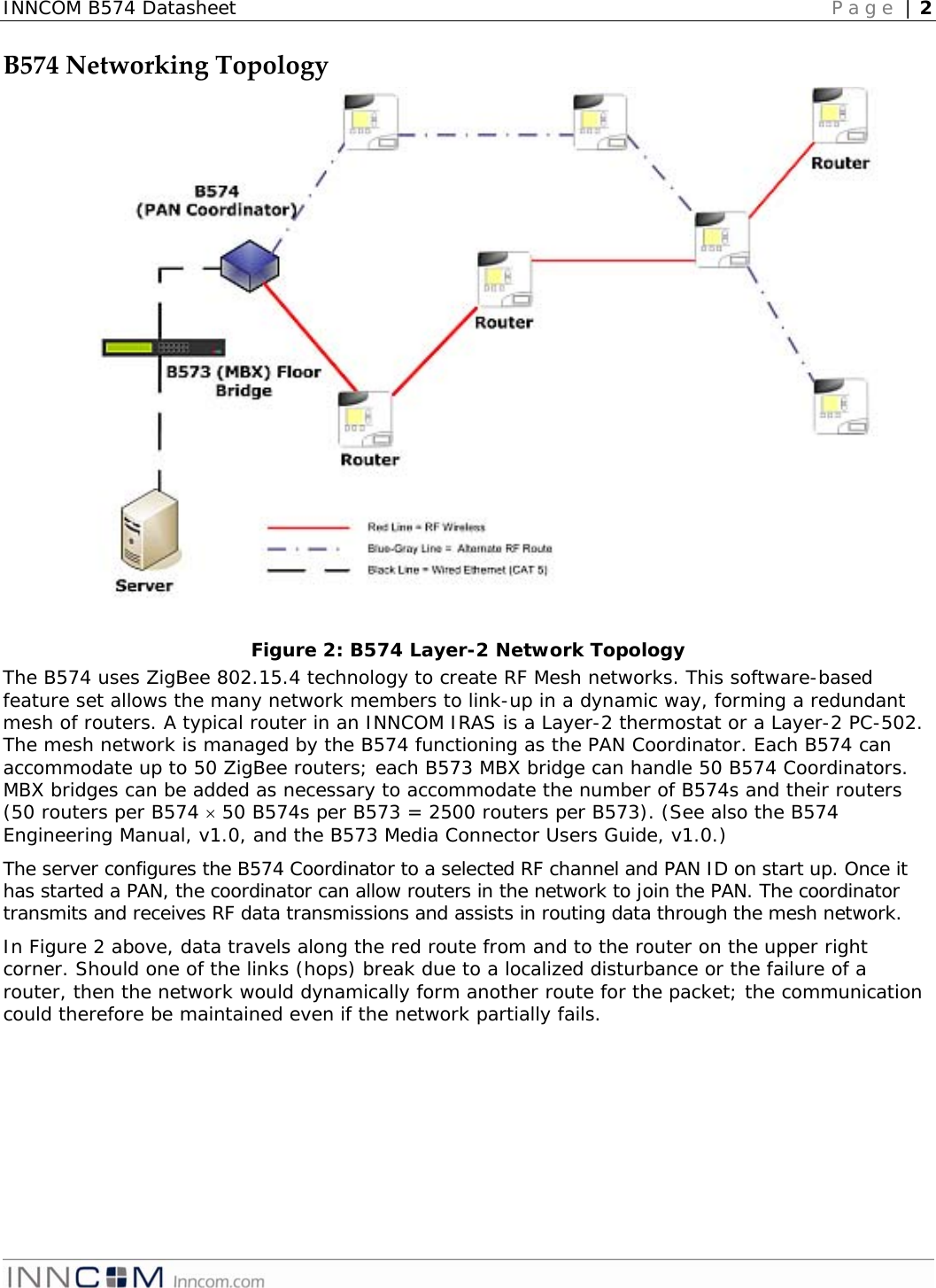
![INNCOMB574DatasheetOverviewThe INNCOM B574 Network Controller is an INNCOM Integrated Room Automation System (IRAS) product that provides the PAN Coordinator functionality in INNCOM’s Layer-2 802.15.4 Zigbee Mesh network. The B574 serves as the gateway between the wireless routers sending guestroom network data back to the wired network server, where it can be managed by INNCOM’s building management system (INNControl). Features• Supports PoE (Power over Ethernet)[Note: This feature is not currently implemented] • 128 bit AES encryption • Indoor range up to 100ft • 2.4Ghz IEEE 802.15.4 compliant RF transceiver (CC2430 radio core) • Compact physical dimension • DIN Rail mounting option • In general, 50 B574s can be supported in one network segment* SpecificationParameterB574RF Data Rate 250kbps Indoor/Urban range 100ft Transmit Power approximately 10mW Receive Sensitivity -94.6dBm Frequency Band 2.4Ghz Encryption AES-128 Protocol 802.15.4 Frequency Channels 11-26 Network Topology Mesh Maximum per network segment Up to 50* Supply Voltage 12VDC Current Consumption 200mA Operating Ambient Temperature 0-40 ° C Dimensions 86mm x 78mm x 40mm Agency Approvals FCC Part 15, CE Mark ETSI, RoHS *Actualnetworksupportmaybehigherorlower,dependingontrafficpatterns,selectedantennatypes,andenvironmentalconsiderations.Figure 1: B574](https://usermanual.wiki/Honeywell/01-9437/User-Guide-1259901-Page-1.png)
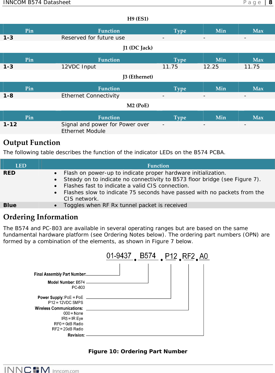
![INNCOM B574 Datasheet Page | 9 OrderingNotesB574B574 is the Layer-2 mesh network controller. This configuration is used in Layer-2 applications only. This configuration will never require the IR5 option but is typically ordered with a 20dB TXR radio as the wireless communications option. This product can be powered from the PoE or 12VDC SMPS. Ensure that the B574 shelf software is specified when ordering in this configuration. PC‐803[Note:Currently,thereisnosoftwareapplicationavailableforthisconfiguration]The PC-803 (protocol converter) is the room gateway configuration of the product. In this configuration, the product converts in-room IR, RF (Layer-1), or S5bus traffic to Ethernet towards the server. The PC-803 mirrors the TCT in functionality with the addition of Layer-1 capability. Order this product with a 0dB TXR radio unless otherwise specified. The radio and IR5 module are mutually exclusive; they cannot be used simultaneously in the same unit (but the PC-803 can accommodate an external IR5 Eye). Ensure that the PC-803 shelf software is specified when ordering in this configuration. Examples:01-9437.B574.P12.RF2.A0: A B574 supplied with an external power supply (04-4040), populated with a 20dB Radio (02-9894), and no IR5 eye. This is a typical configuration for the B574. 01-9437.PC-803.POE.RF0.A0: A PC-803 supplied with the PoE module for power (02-9949), 0db Radio (02-9994). Sub‐assemblies:PartNameDescriptionPartNumberB574/PC-803 logic board Logic board 02-9845 PoE Power over Ethernet Module 02-9949 12VDC SMPS External 12VDC Power Supply 04-4040 0 dB Radio 0db RF TXR radio module 02-9994 20 dB Radio 20dB RF TXR radio module 02-9894 IR5 Eye IR5 Eye 02-9467 PSH1-L12 Power supply module (logic board) 02-4052 ReferencesTitleLocationB574 Engineering Manual T:\Library\INNCOM Products\Devices\B574-(TCT.RF)\B574 Engineering Manual, v1.0 EM.pdf B573 Users Guide T:\Library\INNCOM Products\Systems\IWAN_Reference\Docu\B573_MC Users Guide.pdf DocumentRevisionHistoryRevisionDateIssued Reason0.1 12-Jun-2009 FCC for B574 0.2 24-Jun-2009 Edited for sense and format 0.3 29-Jun-2009 Incorporated review comments 0.4 08-Jul-2009 Clarified network bridge language and capacity 0.5 22-Jul-2009 Incorporated final R&D review comments 1.0 03-Aug-2009 Incorporated Approvers’ comments and released.](https://usermanual.wiki/Honeywell/01-9437/User-Guide-1259901-Page-9.png)