Honeywell 01-9437 B574 NETWORK CONTROLLER User Manual B574 Datasheet v1 0 DS
INNCOM International Inc. B574 NETWORK CONTROLLER B574 Datasheet v1 0 DS
Users Manual
INNCOMB574Datasheet
Overview
The INNCOM B574 Network Controller is an INNCOM
Integrated Room Automation System (IRAS) product that
provides the PAN Coordinator functionality in INNCOM’s
Layer-2 802.15.4 Zigbee Mesh network. The B574 serves
as the gateway between the wireless routers sending
guestroom network data back to the wired network
server, where it can be managed by INNCOM’s building
management system (INNControl).
Features
• Supports PoE (Power over Ethernet)[Note: This feature
is not currently implemented]
• 128 bit AES encryption
• Indoor range up to 100ft
• 2.4Ghz IEEE 802.15.4 compliant RF transceiver
(CC2430 radio core)
• Compact physical dimension
• DIN Rail mounting option
• In general, 50 B574s can be supported in one network segment*
Specification
ParameterB574
RF Data Rate 250kbps
Indoor/Urban range 100ft
Transmit Power approximately 10mW
Receive Sensitivity -94.6dBm
Frequency Band 2.4Ghz
Encryption AES-128
Protocol 802.15.4
Frequency Channels 11-26
Network Topology Mesh
Maximum per network segment Up to 50*
Supply Voltage 12VDC
Current Consumption 200mA
Operating Ambient Temperature 0-40 ° C
Dimensions 86mm x 78mm x 40mm
Agency Approvals FCC Part 15, CE Mark ETSI, RoHS
*Actualnetworksupportmaybehigherorlower,dependingontrafficpatterns,selectedantennatypes,andenvironmental
considerations.
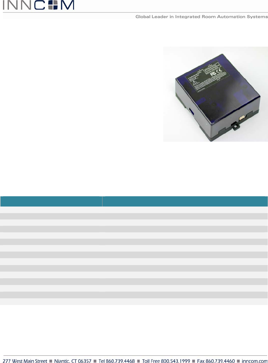
Figure 1: B574
INNCOM B574 Datasheet Page | 2
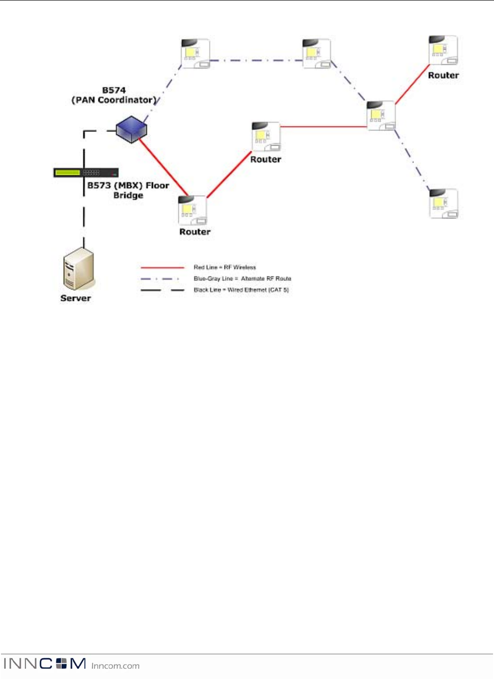
B574NetworkingTopology
Figure 2: B574 Layer-2 Network Topology
The B574 uses ZigBee 802.15.4 technology to create RF Mesh networks. This software-based
feature set allows the many network members to link-up in a dynamic way, forming a redundant
mesh of routers. A typical router in an INNCOM IRAS is a Layer-2 thermostat or a Layer-2 PC-502.
The mesh network is managed by the B574 functioning as the PAN Coordinator. Each B574 can
accommodate up to 50 ZigBee routers; each B573 MBX bridge can handle 50 B574 Coordinators.
MBX bridges can be added as necessary to accommodate the number of B574s and their routers
(50 routers per B574 × 50 B574s per B573 = 2500 routers per B573). (See also the B574
Engineering Manual, v1.0, and the B573 Media Connector Users Guide, v1.0.)
The server configures the B574 Coordinator to a selected RF channel and PAN ID on start up. Once it
has started a PAN, the coordinator can allow routers in the network to join the PAN. The coordinator
transmits and receives RF data transmissions and assists in routing data through the mesh network.
In Figure 2 above, data travels along the red route from and to the router on the upper right
corner. Should one of the links (hops) break due to a localized disturbance or the failure of a
router, then the network would dynamically form another route for the packet; the communication
could therefore be maintained even if the network partially fails.
INNCOM B574 Datasheet Page | 3
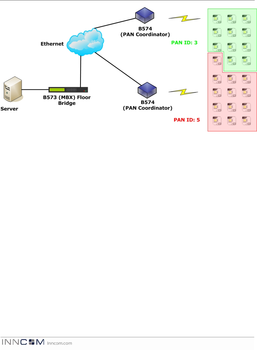
Figure 3 B574 IP Network Topology
An IP network based on Ethernet technology serves as the backbone network linking the B574 with
the server. The B574 uses a wired Ethernet connection to the B573 (MBX) bridge that communicates
with the server using a UDP protocol. In the drawing above, the Layer-2 networks are segregated by
PAN ID. Note that the routers in each PAN do not necessarily need to be physically located in
geographically segregated locations. If a router can make a solid RF connection into a network, then
the router could be geographically located in a neighboring PAN location.
INNCOM B574 Datasheet Page | 4
MechanicalDrawings
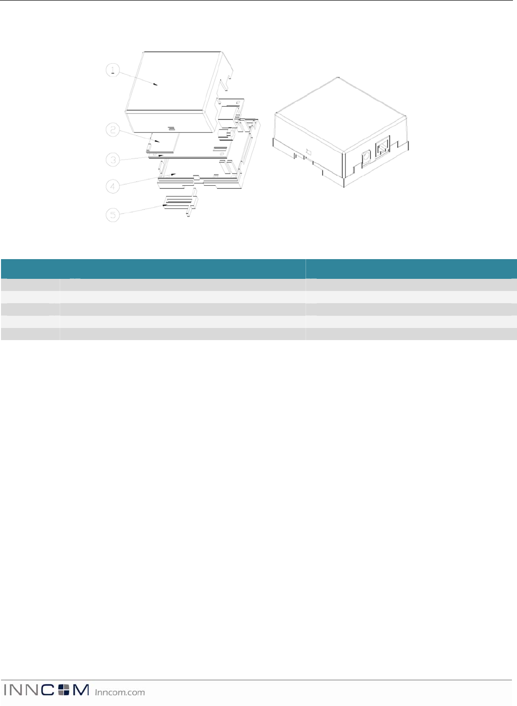
Figure 4: Mechanical Drawings
ItemDescriptionPartNumber
1 Top Housing 53-8084
2 Radio Module 02-9994
3 Main PCBA 02-9845
4 Bottom Housing 53-9918
5 Din Rail Tab 53-9919
MountingConsiderations
The B574 Network Controllers are designed for mounting in a variety of applications. The bottom
housing is equipped with a channel and tab for DIN rail mounting and therefore does not require
any additional screws or hardware for installation. For screw-mounted applications, there are 4
countersunk holes located in the bottom housing that can be accessed by removing the top cover
and Printed Circuit Board Assembly (PCBA).
INNCOM B574 Datasheet Page | 5
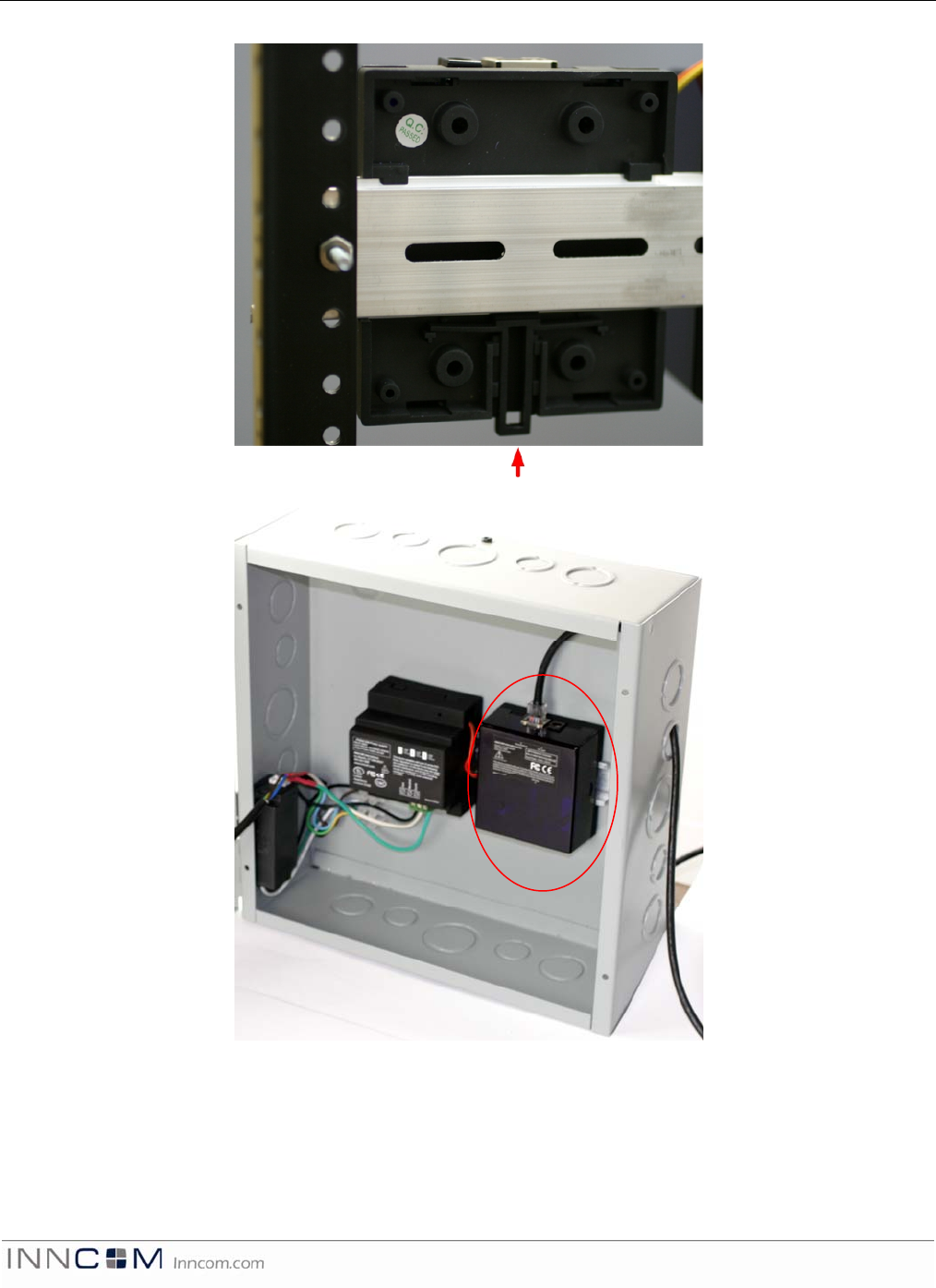
The B574 can be attached to an X-type DIN rail. To attach the B574 to a DIN rail, pull the tab (Figure
5) down and attach the bottom of the housing to the DIN rail (always mount the DIN rail with the tab
at the bottom). Once the unit is sitting flush on the rail, release the tab. To remove the B574 from the
DIN rail, pull the tab down and lift the bottom edge of the unit off the DIN rail first. This ensures that
TAB
Figure 5: B574 DIN Rail Installation
B574.RF
Figure 6: B574 Series DIN Rail Mounted
INNCOM B574 Datasheet Page | 6
the cable, cable channels and connections are always aligned in the correct orientation in a daisy-
chained application.
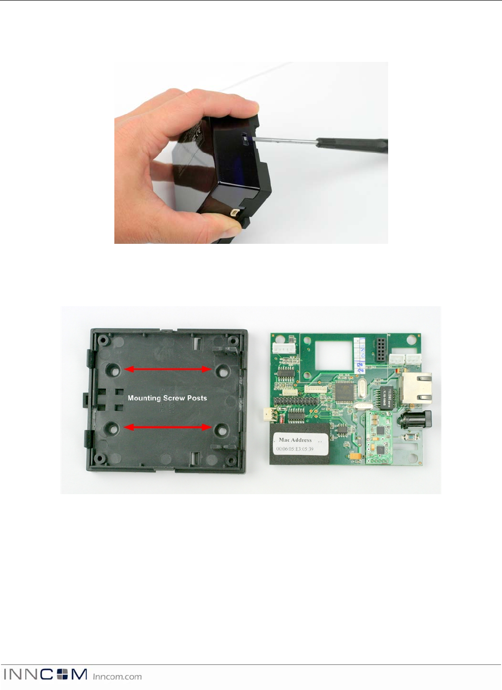
Figure 7 B574 Top Housing Removal
To gain access to headers and connectors located on the PCBA, remove the B574 from the DIN rail
or NEMA box enclosure. Using a flat screw driver, lift the top housing away from the snap tangs on
the bottom housing.
Figure 8 B574 Mounting Screw Locations
To screw mount the B574, open the B574 as described above and remove the PCBA. The PCBA is
held in place by 4 tangs located at the perimeter of the PCBA. Once the PCBA is removed, locate
the 4 countersink posts. Using a self-tapping screw, mount the bottom housing to the intended
fixture. Mount the PCBA back on to the bottom housing, make the necessary wire connections (see
Headers and Connectors below), connect power to DC jack, plug in Ethernet connection, and then
snap the top housing back onto the unit.
INNCOM B574 Datasheet Page | 7
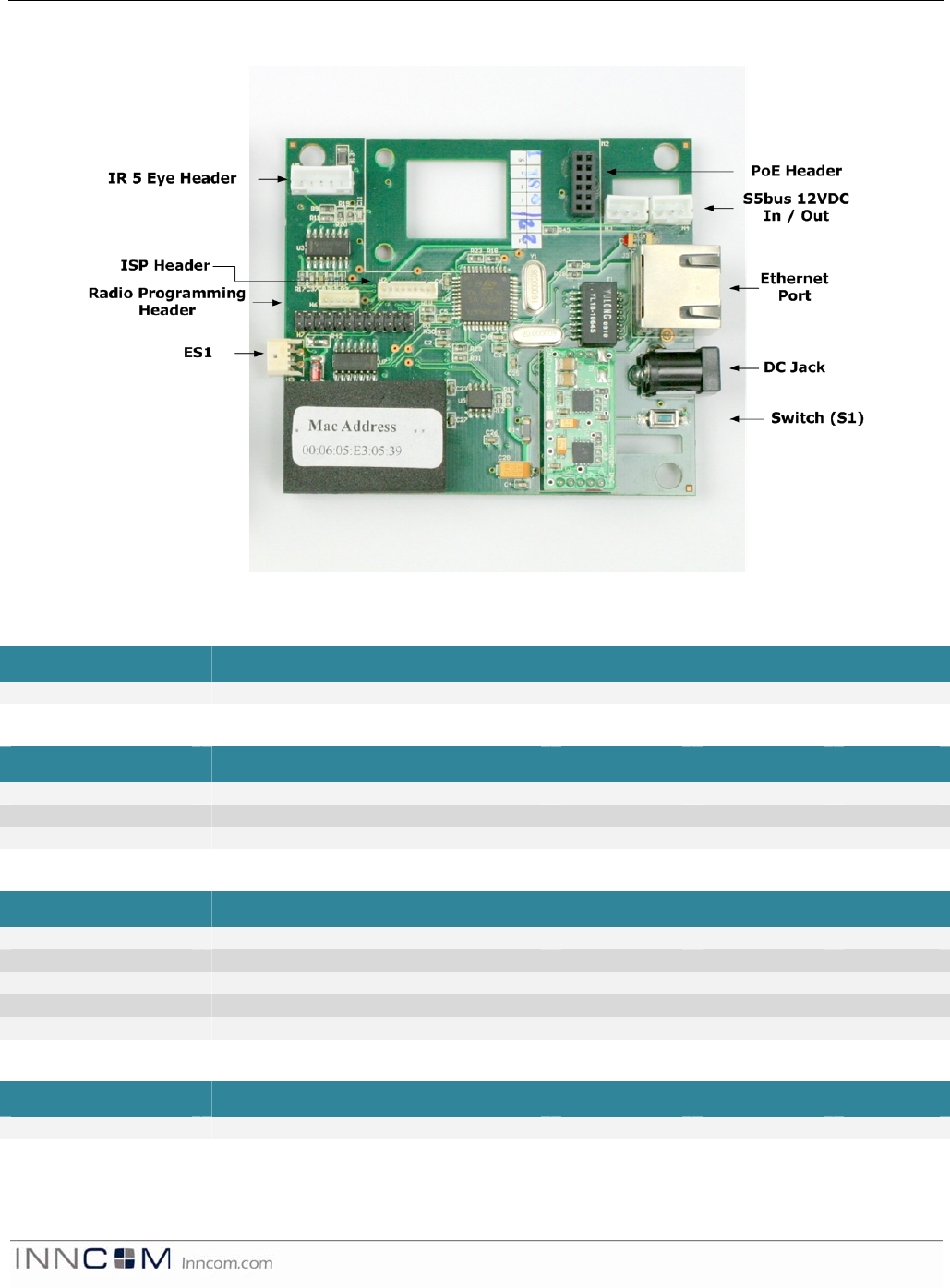
HeadersandConnections
Figure 9 B574 Connections
H2(InSystemProgramming)
PinFunctionTypeMinMax
1-8 Various signals for programming - - -
H3/H4(S5‐busIn/Out)
PinFunctionTypeMinMax
1-GND Common - - -
2-12VDC Input voltage In 11.75 12.25
3-S5-bus Multi-drop In/Out - -
H5(IR‐Eye)
PinFunctionTypeMinMax
1-GND Common - - -
2-AGC Gain control - - -
3-12VDC Input voltage In/Out 11.75 12.25
4 –IRTx Transmit Out - -
5- IRRx Receive In - -
H6(RadioProgramming)
PinFunctionTypeMinMax
1-5 Various signals for programming - - -
INNCOM B574 Datasheet Page | 8
H9(ES1)
PinFunctionTypeMinMax
1-3 Reserved for future use - - -
J1(DCJack)
PinFunctionTypeMinMax
1-3 12VDC Input 11.75 12.25 11.75
J3(Ethernet)
PinFunctionTypeMinMax
1-8 Ethernet Connectivity - - -
M2(PoE)
PinFunctionTypeMinMax
1-12 Signal and power for Power over
Ethernet Module - - -
OutputFunction
The following table describes the function of the indicator LEDs on the B574 PCBA.
LEDFunction
RED • Flash on power-up to indicate proper hardware initialization.
• Steady on to indicate no connectivity to B573 floor bridge (see Figure 7).
• Flashes fast to indicate a valid CIS connection.
• Flashes slow to indicate 75 seconds have passed with no packets from the
CIS network.
Blue • Toggles when RF Rx tunnel packet is received
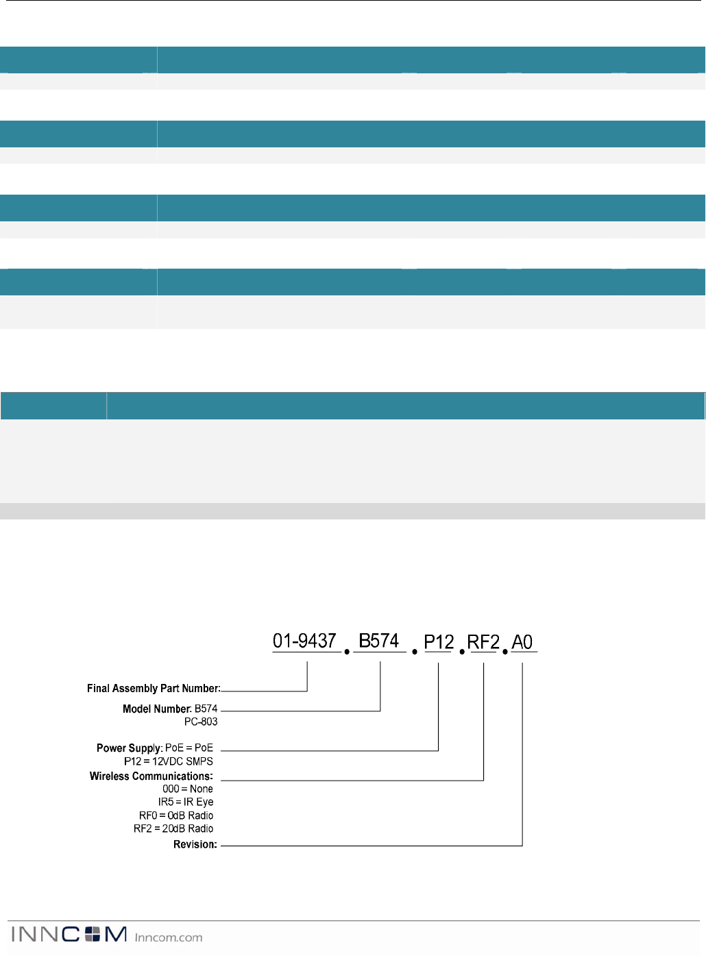
OrderingInformation
The B574 and PC-803 are available in several operating ranges but are based on the same
fundamental hardware platform (see Ordering Notes below). The ordering part numbers (OPN) are
formed by a combination of the elements, as shown in Figure 7 below.
Figure 10: Ordering Part Number

INNCOM B574 Datasheet Page | 9
OrderingNotes
B574
B574 is the Layer-2 mesh network controller. This configuration is used in Layer-2 applications
only. This configuration will never require the IR5 option but is typically ordered with a 20dB TXR
radio as the wireless communications option. This product can be powered from the PoE or 12VDC
SMPS. Ensure that the B574 shelf software is specified when ordering in this configuration.
PC‐803[Note:Currently,thereisnosoftwareapplicationavailableforthisconfiguration]
The PC-803 (protocol converter) is the room gateway configuration of the product. In this
configuration, the product converts in-room IR, RF (Layer-1), or S5bus traffic to Ethernet towards
the server. The PC-803 mirrors the TCT in functionality with the addition of Layer-1 capability.
Order this product with a 0dB TXR radio unless otherwise specified. The radio and IR5 module are
mutually exclusive; they cannot be used simultaneously in the same unit (but the PC-803 can
accommodate an external IR5 Eye). Ensure that the PC-803 shelf software is specified when
ordering in this configuration.
Examples:
01-9437.B574.P12.RF2.A0: A B574 supplied with an external power supply (04-4040),
populated with a 20dB Radio (02-9894), and no IR5 eye. This is a typical configuration for the
B574.
01-9437.PC-803.POE.RF0.A0: A PC-803 supplied with the PoE module for power (02-9949), 0db
Radio (02-9994).
Sub‐assemblies:
PartNameDescriptionPartNumber
B574/PC-803 logic board Logic board 02-9845
PoE Power over Ethernet Module 02-9949
12VDC SMPS External 12VDC Power Supply 04-4040
0 dB Radio 0db RF TXR radio module 02-9994
20 dB Radio 20dB RF TXR radio module 02-9894
IR5 Eye IR5 Eye 02-9467
PSH1-L12 Power supply module (logic board) 02-4052
References
TitleLocation
B574 Engineering Manual T:\Library\INNCOM Products\Devices\B574-(TCT.RF)\B574 Engineering Manual, v1.0
EM.pdf
B573 Users Guide T:\Library\INNCOM Products\Systems\IWAN_Reference\Docu\B573_MC Users
Guide.pdf
DocumentRevisionHistory
RevisionDateIssued Reason
0.1 12-Jun-2009 FCC for B574
0.2 24-Jun-2009 Edited for sense and format
0.3 29-Jun-2009 Incorporated review comments
0.4 08-Jul-2009 Clarified network bridge language and capacity
0.5 22-Jul-2009 Incorporated final R&D review comments
1.0 03-Aug-2009 Incorporated Approvers’ comments and released.
FCC NOTE:
This device complies with Part 15 of the FCC Rules. Operation is subject to the following two
conditions:(1)this device may not cause harmful interference, and (2) this device must accept
any interference received, including interference that may cause undesired operation.
The manufacturer is not responsible for any radio or TV interference caused by unauthorized
modifications to this equipment. Such modifications could void the user's authority to operate
the equipment.