Honeywell 202111TXR Switch User Manual EVORA Datasheet v2 0
INNCOM International Inc. Switch EVORA Datasheet v2 0
Manual.pdf
Confidential Copyright © 2012 INNCOM
EVORA Series Datasheet
Overview
The EVORA family of switches offers an elegantly designed, easy to use,
feature-rich user interface and control system providing a state-of-the-art
guestroom automation experience. EVORA allows guest control of multiple
lighting loads, temperature, drapes, and guest annunciation from multiple
switch locations in the guestroom. EVORA offers three different user interface
modules and multiple different Load Assemblies that include wired and
wireless communications, dimmers, and programmable controls designed to
operate within INNCOM’s Integrated Room Automation System (IRAS). The
EVORA system brings all guestroom control features into a sleekly designed
traditional keypad user interface.
Features
• Up to 7 key configurations with up to 5 position key pad for programmable control of any IRAS feature
• Nightlight configuration with 2 key positions
• Doorbell configuration with 2 key positions
• Optional multifunction key for up to 10 grouped features per device
• Backlight illuminated keys and text
• TRIAC dimmer
• FET dimmer
• Relay actuator
• Master contactor application
• 12VDC power supply
• Low-voltage adapter for load center applications
• 2.4Ghz 802.15.4 wireless RF network communications
• S5bus wired network communications
• Digital input for door switch contact / integration with the INNCOM energy management system (EMS)
• Software programmable for any CBL feature
Application
EVORA was developed to extend INNCOM switch capabilities beyond those offered in the well-established S-
Series (S217 and S5XX) product families and the innovative MODEVA series. The EVORA series uses a modular,
cross functional hardware platform that allows each of the three main products (multifunctional switch,
nightlight, and doorbell ) to share features in both hardware and software that were previously available only as
uniquely designed sub-assemblies in the legacy S-Series products.
EVORA has at its core the same Load Assembly (WBI) architecture used by INNCOM’s MODEVA line. The Load
Assembly is available in six configurations—500W relay, 500W TRIAC dimmer, 350W FET dimmer, 30A master
contactor, 200mA power supply, and a low-voltage adapter (LVA)—that provide the mechanical platform and load
bearing capability for the EVORA system. The EVORA series differs from MODEVA in several ways. It uses a
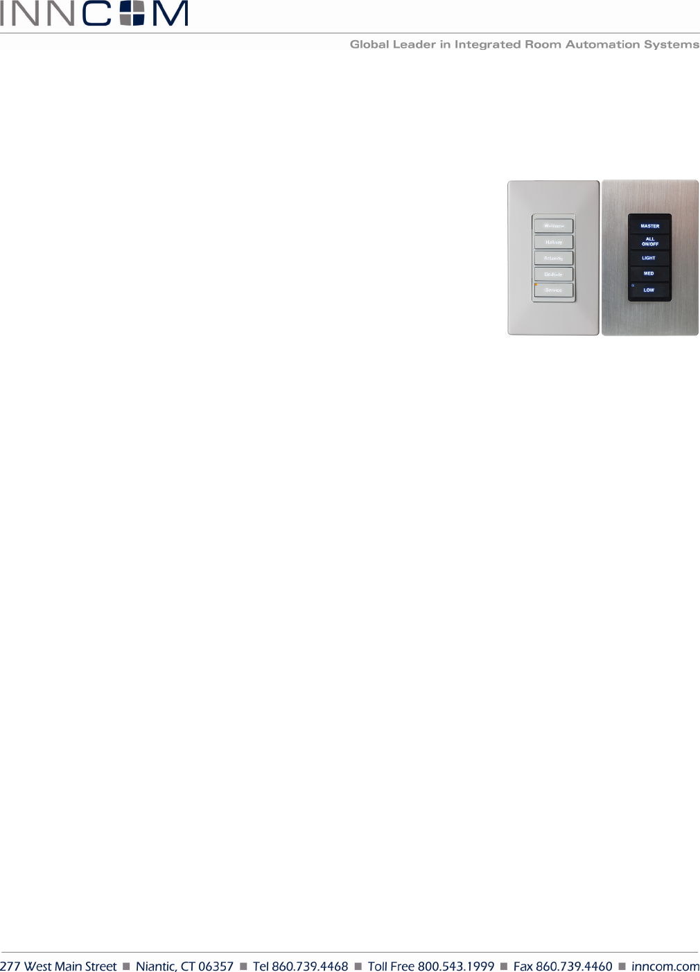
Figure
1
EVORA Switch

E V O R A D a t a s h e e t P a g e 2 o f 1 0
standard dimension mounting bracket, for instance, allowing EVORAs to be ganged with other products (similar to
the S-Series). EVORA products come factory assembled.
Categories of Load Assembly Load Switching
• TRIAC dimmer provides dimming control of resistive light loads such as incandescent, halogen, and
TRIAC dimmable LEDs. The TRIAC dimmer can dim 100–120VAC loads up to 500W.
• FET dimmer dims capacitive loads such as dimmable fluorescent lamps and electronic ballasts. It can also
dim resistive loads such as incandescent, halogen, and dimmable LEDs. The FET dimmer is designed to
dim 100–120VAC up to 350W.
• Relay power supply switches capacitive, inductive, resistive, and general purpose loads up to 500W.
• Master contactor controls 30A relay at 120–240VAC.
• 200mA power supply used for applications where EVORA must be line powered but does not require
load dimming or switching.
• Low-voltage adapter allows the EVORA products to run in a +12VDC powered device that does not
actuate a load. This is very similar to the legacy S5XX product.
Load Assembly Parallel Power Supplies
The WBI actuators operate in parallel to supply a higher load capacity on the +12VDC rail than that achievable by a
single actuator. The total output power of the actuators in parallel is based on the voltage specifications at maximum
load versus the output current at maximum load and nominal recovery time after a foldback condition occurs. This
design can aggregate up to 6 actuators into a system that permits up to a combined 990mA (~1A) +12VDC output.
See Class 2 Output table below.
Additional Load Assembly Technical Features
• Air-gap relay required (for dimmers meeting UL 508). Where solid state dimmers are used, disengages
the load from the line power in the event that a failed actuator causes a short or a closed circuit (as with a
FET dimmer), a possible electric shock risk during routine maintenance or lamp replacement.
• Additional overload detection circuit for FET dimmer that senses a catastrophic overload / short and
shuts down the dimmer to protect the solid state circuitry.
• Dimming linearization curve may be set by application engineer to calibrate the duty cycle of a Pulse
Width Modulated signal driving the various lamp types that could be used.
• Self contained actuator that can be used without the user interface. This is useful during installation (with
EVORA) and in repair to isolate symptoms related specifically to the actuator.
Load Assembly Installation
Locate the fuse panel and remove fuses or ensure the breaker is in the OFF position before installing the Load
Assembly.
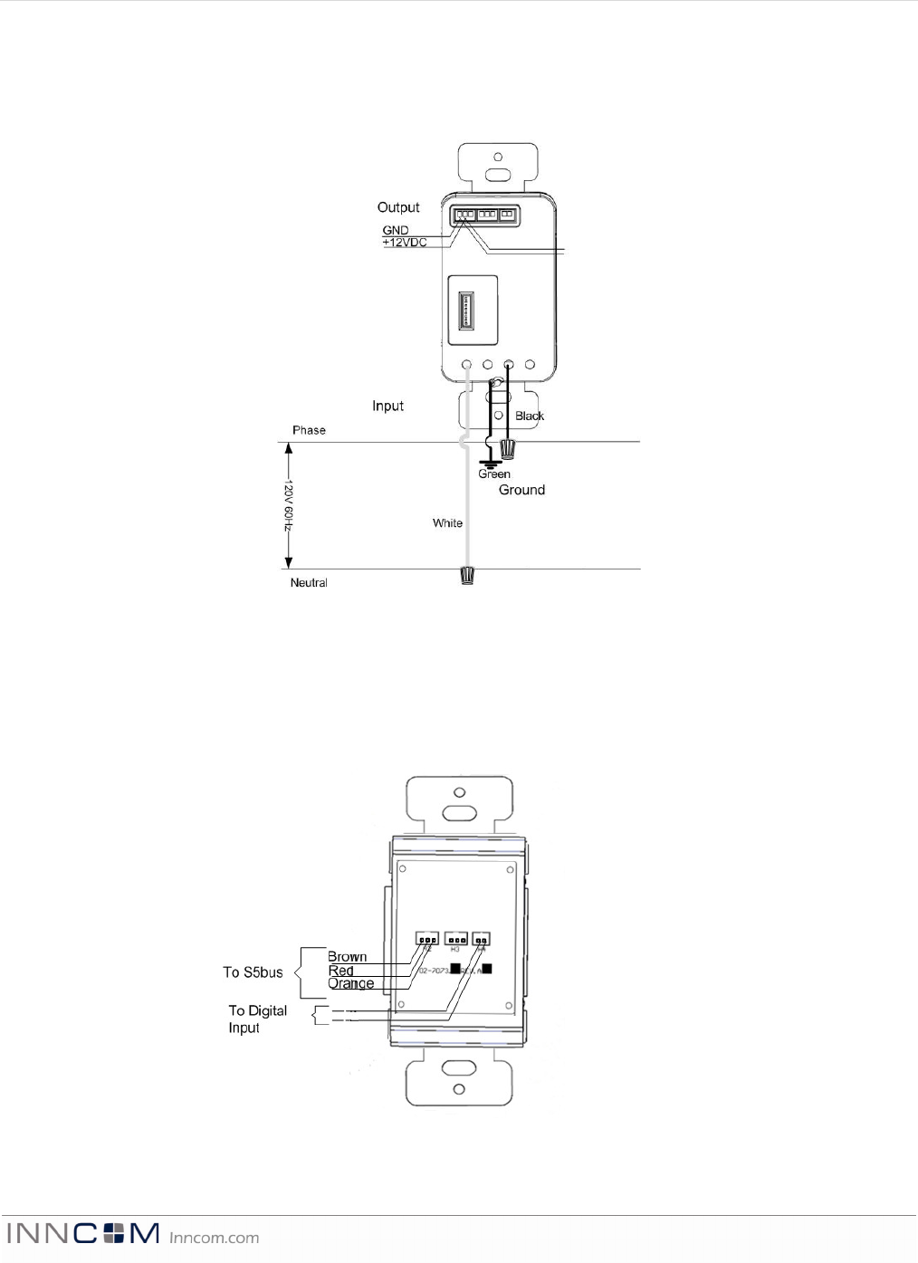
1. Pull the class-2 wires for Ground (Brown), +12VDC (Red) and S5bus (Orange) and digital inputs into the
wall box (See Wiring Diagrams). Make the connections using a dolphin DC-1000P Super B connector or
equivalent type connector to the S5bus or digital input harnesses and connect them to the appropriate
header on the Load Assembly.
2. Prepare the line voltage wiring by stripping back the insulation 16mm (5/8th inch).
3. Connect the Green (Earth) Cable attached to the Load Assembly Strap to Earth.
E V O R A D a t a s h e e t P a g e 3 o f 1 0
4. Wire the Load Assembly as described in the Wiring Diagrams. Depending on gang assembly using the
appropriate 10, 12, 14, 16, or 18 AWG wire nut.
5. Push all wires back into the wall box and fasten the control to the wall box using the supplied mounting
screws. Be sure not to pinch or disconnect any of the wires.
6. Ensure the intended load(s) are connected to the circuit.
7. Replace the fuses in the fuse panel or move the breaker to ON before continuing.
Note: EVORA self test may require that an I/O map is configured. The following steps are general
guidance only. Installers should refer to the property-specific install and commissioning
documents for further guidance.
8. Allow the EVORA switch to power up. To verify power, observe whether indicator light or backlight
illuminate or blink.
9. Testing EVORA depends on the specific software configuration.
10. The EVORA User Interface will display start up behavior (refer to the property-specific installation and
commissioning guide(s) and then enter a self test mode for the first 20 seconds of operation.
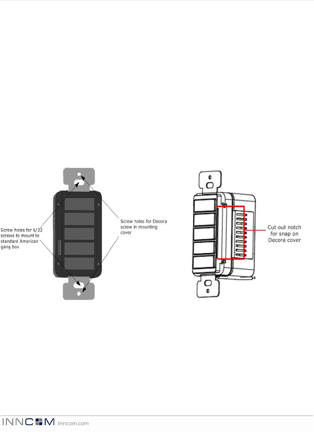
Figure
2
Mounting Screw Holes
Figure 3 Decora Notch
E V O R A D a t a s h e e t P a g e 4 o f 1 0
The EVORA and Load Assembly is supplied with two 1¼" 6/32 screws, two 3-pin S5bus harnesses and a two-pin
pig-tail harness for the digital input.
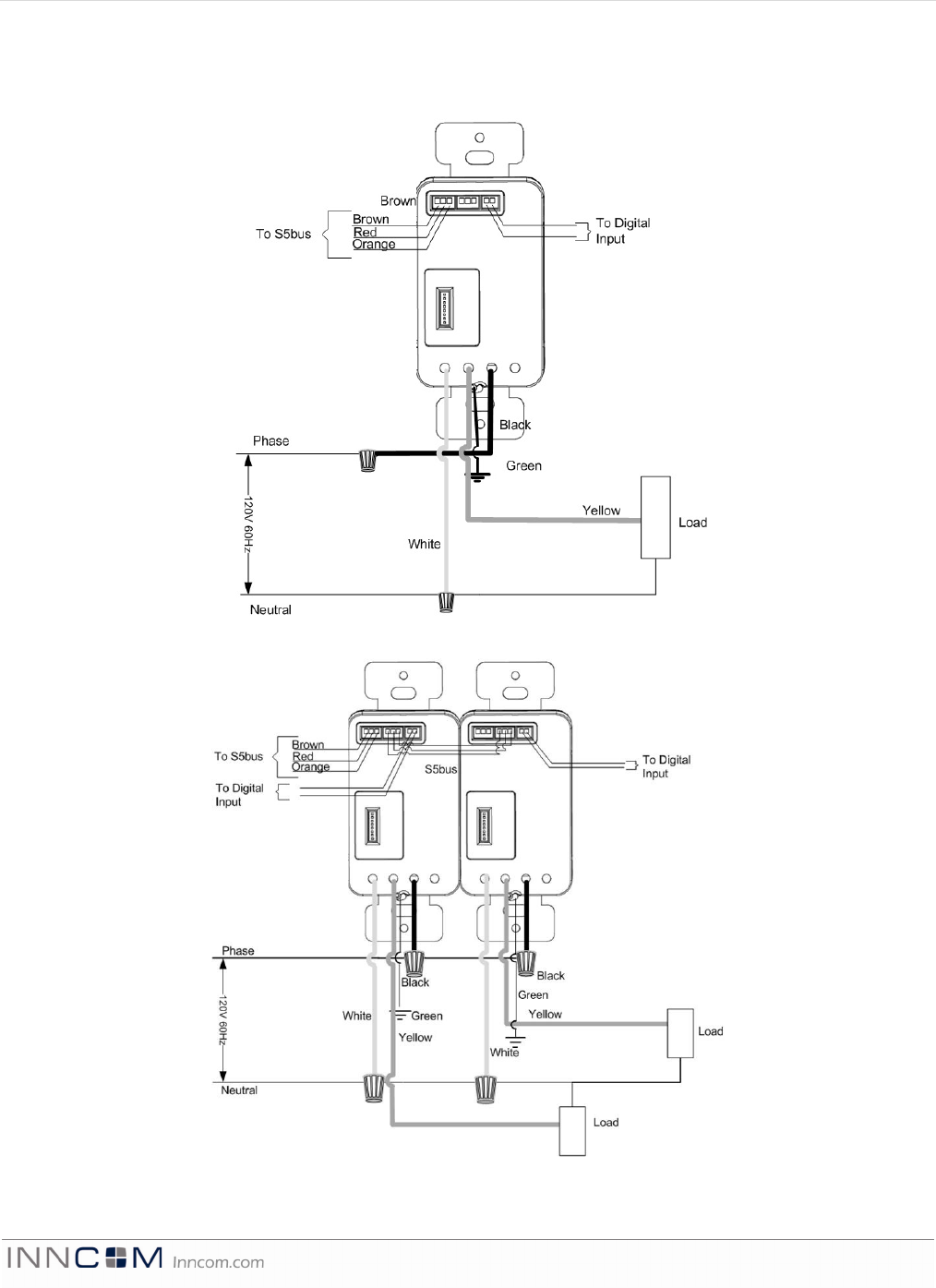
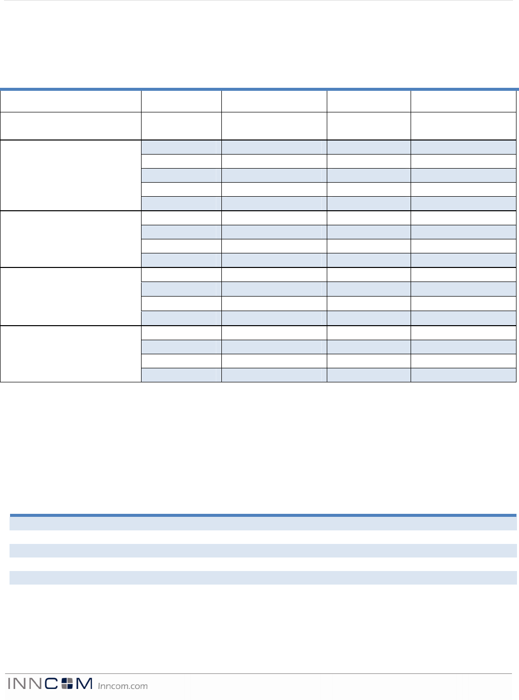
Wiring Diagrams
Figure 4 EVORA WBI Single Wiring
Figure 5 EVORA WBI Double Wiring
E V O R A D a t a s h e e t P a g e 5 o f 1 0
In double and triple configurations, refer to the wiring diagram for S5bus and digital input connections. Daisy
chaining is required only if all EVORA units need to be on the same S5bus or a parallel power design is needed
for higher load capacity (See Class 2 Output table below).
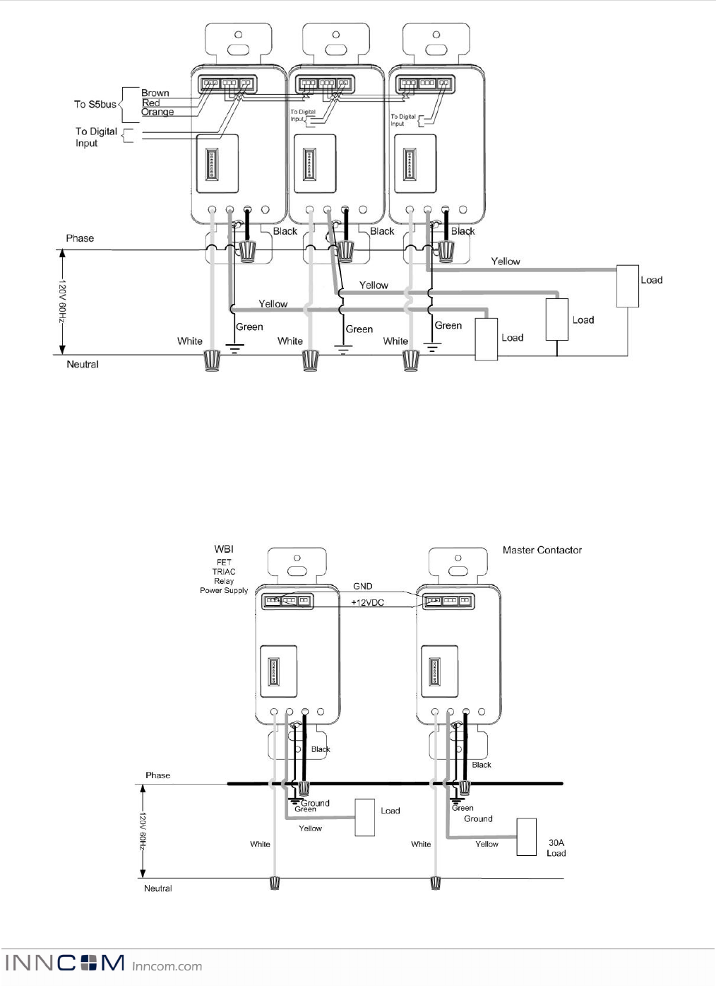
Master Contactor
Use for master contactor applications up to 30A. This assembly requires an external +12VDC source.
Figure 6 EVORA WBI Triple Wiring
Figure 7 EVORA WBI Master Contactor Wiring
E V O R A D a t a s h e e t P a g e 6 o f 1 0
WBI Power Supply
Use for applications where EVORA must be line powered but does not require load dimming or switching.
200mA DC output.
Low Voltage Adapter
The EVORA can be equipped with the Low Voltage Adapter (LVA). This allows the EVORA to act as a remote,
+12VDC powered device only.
Figure 8 EVORA WBI Power Supply Wiring
Figure 9 EVORA WBI Low Voltage Adapter Wiring

E V O R A D a t a s h e e t P a g e 7 o f 1 0
Technical Specifications
User Interface Tactile input
Maximum # of inputs 1-7 tactile keys
Alternate User Interface Keypad—traditional mechanical switches
Communications Wired S5bus
2.4Ghz RF
Input Power 12VDC, up to 250mA*
Audio 8 ohm, 0.5W speaker for door bell chime
Micro controller 16Mhz, 32-bit ARM based MCU
Dimensions 1 3/4” W x 1 3/4” D x4” H (including brackets)
45 mm W x 45 mm D x 100 mm H (including brackets)
FCC ID: GTC202111TXR
This equipment has been tested and found to comply with the limits for a Class B digital device, pursuant to Part
15 of the FCC Rules. These limits are designed to provide reasonable protection against harmful interference in a
residential installation. This equipment generates uses and can radiate radio frequency energy and, if not
installed and used in accordance with the instructions, may cause harmful interference to radio communications.
However, there is no guarantee that interference will not occur in a particular installation. If this equipment does
cause harmful interference to radio or television reception, which can be determined by turning the equipment off
and on, the user is encouraged to try to correct the interference by one of the following measures:
— Reorient or relocate the receiving antenna.
— Increase the separation between the equipment and receiver.
— Connect the equipment into an outlet on a circuit different from that to which the receiver is connected.
— Consult the dealer or an experienced radio/TV technician for help.
Any changes or modifications not expressly approved by the party responsible for compliance could void the
user's authority to operate this equipment.
IC: 1609A-201217TXR
This device complies with Industry Canada licence-exempt RSS standard(s). Operation is subject to the following two
conditions: (1) this device may not cause interference, and (2) this device must accept any interference, including interference
that may cause undesired operation of the device.
Le présent appareil est conforme aux CNR d’industrie Canada applicables aux appareils radio exempts de licence.
L’exploitation est autorisée aux deux conditions suivantes: (1) l’appareil ne doit pas produire de brouillage, et (2) l’utilisateur
de l’appareil doit accepter tout brouillage radioélectrique subi, même si le brouillage est susceptible d’en compromettre le
fonctionnement.
E V O R A D a t a s h e e t P a g e 8 o f 1 0
Load Specifications
Single Gang Installation
The following table provides the load ratings at absolute maximum based on the load type in a single gang wall box.
Actuator Ratings
Voltage Frequency Power / Amperes Load Type
SMPS 120-240Vac 50/60Hz 200mA +12VDC Output
Only
120-240 Vac 50/60 Hz 4.1 A Resistive
120-240 Vac 50/60 Hz 4.1 A General Purpose
120-240 Vac 50/60 Hz 500 W Tungsten / ELV
120-240 Vac 50/60 Hz 250 VA Electric Ballast
Relay Actuator
120 Vac 50/60 Hz 1/10 HP Motor
120 Vac 60 Hz 2.9 A Resistive
120 Vac 60 Hz 500 W Tungsten / ELV
120 Vac 60 Hz 250 VA Electronic Ballast
TRIAC Dimmer
120 Vac 60 Hz 1/10 HP Motor
120 Vac 60 Hz 2.9 A Resistive
120 Vac 60 Hz 2.9 A General Purpose
120 Vac 60 Hz 350 W Tungsten / ELV
MOSFET Dimmer
120 Vac 60 Hz 250 VA Electronic Ballast
120-240 Vac 50/60 Hz 7200VA General Purpose
120-240 Vac 50/60 Hz 960W Tungsten / ELV
120-240 Vac 50/60 Hz 800VA Electronic Ballast
Master Contactor
120-240 Vac 50/60 Hz 30A Resistive
Class-2 Output
The Load Assembly has been designed to provide +12VDC power to devices connected to the S5bus. The Load
Assemblies can operate in parallel to supply a higher total load capacity than that achievable by a single Load
Assembly. However, the total output is derated as per the table below for accommodating the stability of the
power supply circuitry. The total available output power must be shared with the EVORA User Interface. Refer to
the following table for Class-2 Output ratings.
Number of Load
Assemblies
Nominal Voltage Voltage at Maximum
Load
Output Rating
1 +12VDC +11.0VDC 200mA
2 +12VDC +11.0VDC 375mA
3 +12VDC +11.1VDC 550mA
4 +12VDC +11.1VDC 660mA
5 +12VDC +11.2VDC 880mA
6 +12VDC +11.2VDC 990mA
E V O R A D a t a s h e e t P a g e 9 o f 1 0
Operating Conditions
Table Header Table Header
Storage 68-176 degrees F; 20–80 degrees C, non-condensing
Operating 50-122 degrees F; 10–50 degrees C, non-condensing
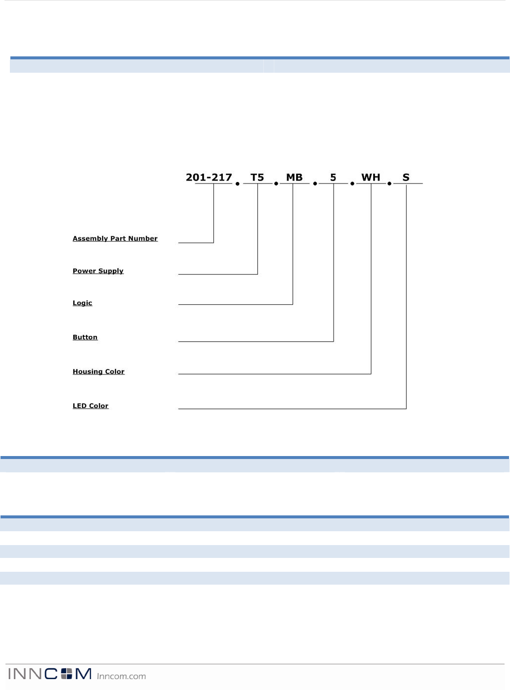
Ordering Information
The highly configurable EVORA product line features many options for function (programmable control, doorbell,
nightlight), appearance, user interface, and Load Assembly. The Ordering Guide below is for the EVORA final
assembly. For detailed ordering information for all EVORA components, see the EVORA Ordering Guide.
Final Assembly
Description OPN Part Number
Multifunction/Doorbell 201-217
Nightlight 201-564
Power Supply
Description OPN Part Number
500W TRIAC Dimmer T5 03-7051
350W FET Dimmer F3 03-7052
500W Relay Actuator R5 03-7050
30A Master Contactor 3M 03-0310
200mA Power Supply PS 03-7053
Low Voltage Adapter LVA 03-7073
E V O R A D a t a s h e e t P a g e 1 0 o f 1 0
Logic
Description OPN Part Number
1–5 button logic board w/radio MB 202-111
2 button nightlight logic board w/
radio
NL 202-113
2 button logic board w/radio DB 202-114
Button
Description OPN Part Number
1, 2, 3, 3b, 4, 4b, 5 button (Nightlight
and Doorbell are 2 button only)
- -
Housing Color
Description OPN Part Number
White WH
Black BK
Light Almond LA
Eagle Almond EA
Document Revision History
Revision Date Issued Reason
0.1 10-Mar-2012 First draft
0.2 15-Mar-2012 Incorporated R&D review comments
0.3 22-Mar-2012 Updated drawings and Load Assembly text
1.0 23-Mar-2012 Incorporated Marketing comments and released
1.01 29-Jun-2012 Incorporate new load assemblies, order guide, IC statement
2.0 07-Sep-2012 Incorporate FCC statement changes and republish