Honeywell 202151TXR Thermostat User Manual E527 Datasheet v1 2 DS
INNCOM International Inc. Thermostat E527 Datasheet v1 2 DS
Manual.pdf
Confidential Copyright © 2012 INNCOM
e527 Datasheet
Overview
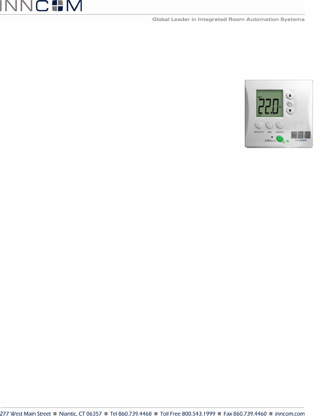
Like the larger e528, the compact, low profile e527 thermostat takes advantage of
component end-of-life to redesign hardware and produce a more efficient, lower cost
device. With onboard radio and RS485 connection and an added CDS light sensor, the
e527 maintains its position as an integral part of the INNCOM Integrated Room
Automation System (IRAS) and a property’s Energy Management System (EMS).
Features
In an EMS, the e527 controls room heating and cooling using occupancy data collected
from motion detectors and door switches and can be networked to the property’s
central management system. As an IRAS device, the e527 can communicate with
devices within a room and function as a room gateway device towards the mesh network.
• British gang mounting (American gang mounting with optional frame)
• Accurate temperature measurement +/- 1 degree F
• External temperature sensor support
• Motion sensor for occupancy detection
• RF transceiver (onboard 802.15.4, 2.4GHz radio) for wireless guestroom and backhaul network
communications
• RS485 for wired backhaul network communications
• Photo sensor for light level detection
Installation Requirements
The e527 must be located on a partitioning interior wall, approximately 5' (1.5 m) above the floor, in a site of
average temperature. It is important to ensure that the thermostat is located away from direct sunlight or radiant
heat, air discharge grilles, stairwells, outside doors, steam or water pipes, warm air stacks, unheated/uncooled
areas, or sources of electrical interference. The unit should not be placed on an outside wall or behind a door.
The e527 is designed to be mounted on a standard British-style single-gang electrical box. For use with an
American box, the e527 can be installed in an optional frame by means of two screws. Screws for attaching the
optional frame and mounting the e527 are included. The device is shipped with a clear clamshell dust cover.
Figure
1
E527
E 5 2 7 D a t a s h e e t P a g e 2 o f 7
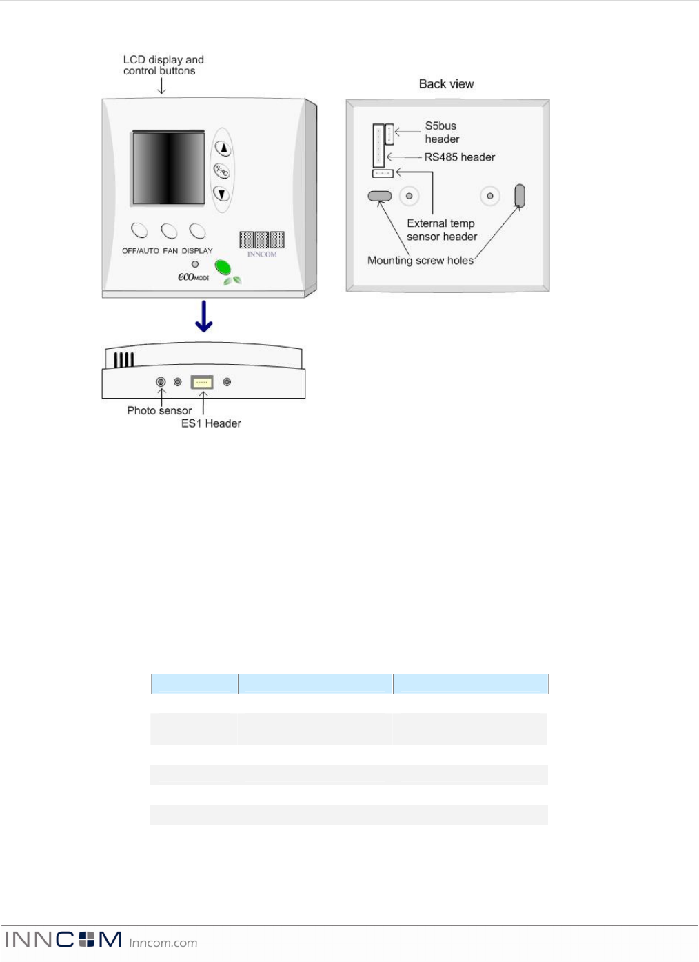
Headers
H1 ICP microprocessor programming
H2 Humidity sensor
H3 System interconnect
H4 PIR sensor
H5 ES1
H6 RS485 network header (see pinout below)
H7 System 5 header (see pinout below)
H8 System interconnect
H9 External temperature control sensor (see pinout below)
H6 Pinout
Pin Function Comment
1 Common GND
Min Nom Max
2 12VDC
10V 12V
14V
3 S5bus Communication bus
4 Dry Input Input
5 RS485B RS485 Twisted Pair
6 RS485A RS485 Twisted Pair
Figure 2 E527 Front/Back and External Headers
E 5 2 7 D a t a s h e e t P a g e 3 o f 7
H7 Pinout
Pin Function Comment
1 Common GND
Min Nom Max
2 12VDC
10V 12V
14V
3 S5bus Communication bus
H9 Pinout
Pin Function Comment
1 Common GND
2 Common GND
3 External temp sensor
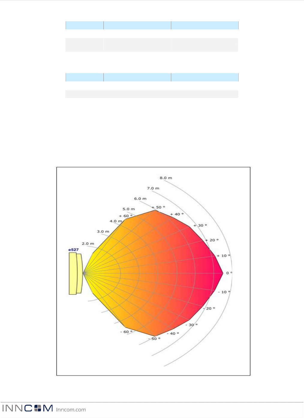
Motion Detection
The optional motion detector available on the e527 works in conjunction with the electronic door lock to
determine room occupancy. If the door lock reports that the door has opened and closed and no motion is
detected in the room for a set number of minutes, the e527 engages energy conservation setbacks. When motion is
detected, the e527 returns to its occupied state. Also, the e527 reports occupancy changes to the central server.
Figure 3 Motion Sensor Sensitivity

E 5 2 7 D a t a s h e e t P a g e 4 o f 7
Network Communication
INNCOM employs a Deep Mesh system to connect guestroom IRAS components to management and monitoring
servers. Because networking infrastructure is embedded in the IRAS devices, command and reporting
information packets can follow multiple network pathways, increasing communication efficiency and reliability
at lower cost. Typically, a Deep Mesh network integrates 50–200 rooms per network segment
*
. INNCOM
generally uses a wireless radio network, but a Deep Mesh system may be constructed using RS485 networks
(topologies that merge RF and RS485 networks are also possible).
2.4GHz Wireless RF
In a typical RF Deep Mesh network, an 802.15.4-based 2.4GHz radio-equipped IRAS device (most often a
thermostat, such as the e527) acts as a room gateway for communication with the network. Data are propagated
among the network nodes until terminated at edge routers that bridge traffic onto IP (Ethernet) networks towards
the servers. The radio specifications are given in the table below:
Performance 0dB
RF Data Rate 250kbps
Antenna Type SMT
Indoor Range 70ft
Outdoor/ RF line-of-sight range 540ft
Transmit Power 1mW
Receive Sensitivity -94.6dBm
Frequency Band 2.4GHz
Encryption AES-128
Protocol 802.15.4
Frequency Channels 11–26
This equipment has been tested and found to comply with the limits for a Class B digital device,
pursuant to Part 15 of the FCC Rules. These limits are designed to provide reasonable protection
against harmful interference in a residential installation. This equipment generates uses and can
radiate radio frequency energy and, if not installed and used in accordance with the instructions,
may cause harmful interference to radio communications. However, there is no guarantee that
interference will not occur in a particular installation. If this equipment does cause harmful
interference to radio or television reception, which can be determined by turning the equipment off
and on, the user is encouraged to try to correct the interference by one of the following measures:
- Reorient or relocate the receiving antenna.
- Increase the separation between the equipment and receiver.
- Connect the equipment into an outlet on a circuit different from that to which the receiver is
connected.
- Consult the dealer or an experienced radio/TV technician for help.
Any changes or modifications not expressly approved by the party responsible for compliance could
void the user's authority to operate this equipment.
*
The network segment size depends on the facility’s layout, expected network traffic, and other environmental considerations.
E 5 2 7 D a t a s h e e t P a g e 5 o f 7
This device complies with Industry Canada licence-exempt RSS standard(s). Operation is subject to
the following two conditions: (1) this device may not cause interference, and (2) this device must
accept any interference, including interference that may cause undesired operation of the device.
Le présent appareil est conforme aux CNR d’industrie Canada applicables aux appareils radio exempts de licence.
L’exploitation est autorisée aux deux conditions suivantes: (1) l’appareil ne doit pas produire de brouillage, et (2) l’utilisateur
de l’appareil doit accepter tout brouillage radioélectrique subi, même si le brouillage est susceptible d’en compromettre le
fonctionnement.
RS485
A Deep Mesh RS485 (DM485) network typically uses a CAT5-type wiring wired as a home-run or daisy-chain.
The DM485 network is routed to a dedicated device in each guestroom. This device becomes the room gateway,
which transfers information packets between the DM485 backbone and the in-room network. The in-room
network can be either S5Bus or a local mesh formed with RF. Each DM485 network is operated by a B575
hardware running DM485 software. Refer to the H6 pinout table above for wiring instructions.
Technical Specifications
Power Requirements 12VDC, 50mA
Thermostat Measurement Range 33 to 99 degrees F (1 to 37 degrees C)
Outdoor Air Temperature Display 0 to 99 degrees F (-18 to 37 degrees C)
Display Resolution Whole degree F, 0.5 degree C (0.1 degree F in test mode)
Standard Deadband 2 degrees F (1 degree C) between heating and cooling
Degrees C/Degrees F Display Toggle Button located on front display
Ambient Operating 41 to 149 degrees F (5 to 65 degrees C), 0-95% RH noncondensing
Ambient Storage 33 to 149 degrees F (1 to 65 degrees C)
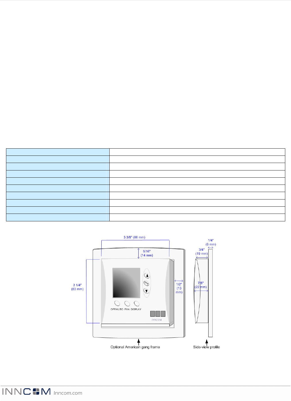
Dimensions 3.5” W x 3.5” H x 0.9” D (89 mm x 89 mm x 23 mm)
Approvals FCC, CE Mark
Figure 4 E527 Dimensions
E 5 2 7 D a t a s h e e t P a g e 6 o f 7
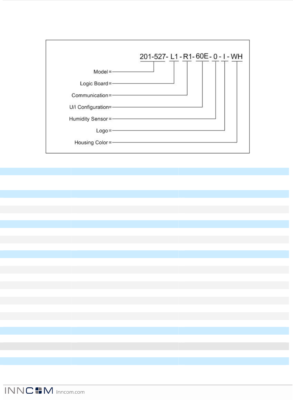
Ordering Information
The e527 is available in several operating configurations, all based on the same fundamental hardware platform.
The ordering part numbers (OPN) are formed by a combination of the elements, as shown below.
Assembly Description Part Number
e527 Final Assembly 201-527
Logic Description Part Number
L0 No Radio Logic Board 202-151.L0
L1 Radio Logic Board 202-151.L1
Communications Description Part Number
R0 No RS485 203-203.R0
R1 RS485 203-203.R1
User Interface Description Part Number
6PE 6 button with PIR and EcoMode 02-9972
6P0 6 button with PIR, without EcoMode 02-9972
60E 6 button EcoMode only
600 6 button no PIR, no EcoMode
5PE 5 button with PIR and EcoMode 02-9972
5P0 5 button with PIR, without EcoMode 02-9972
50E 5 button EcoMode only
500 5 button no PIR, no EcoMode
Humidity Sensor Description Part Number
0 No Humidity Sensor
1 Humidity Sensor 02-9463
Logo OPN Description
0 No Logo

E 5 2 7 D a t a s h e e t P a g e 7 o f 7
Logo OPN Description
I INNCOM Logo
J Johnson Controls Logo
Housing Color OPN Description
WH White
BK Black
LA Light Almond
EA Eagle Almond
For American gang installation, add mounting plate 53-6092. Use wiring harness 62-1462 for the RS485 connection
and 62-1465 for S5 and external temperature sensor.
Document Revision History
Revision Date Issued Reason
0.1 01-Jun-2012 First Draft
0.2 05-Jun-2012 Incorporated comments from AE review
0.3 20-Jun-2012 Incorporated R&D review comments
0.4 09-Jul-2012 Incorporated RS485 Deep Mesh information
1.0 09-Jul-2012 Finalized for release
1.1 07-Sep-2012 Added FCC language change