Honeywell 202517TXR Motion Sensor User Manual K595 Datasheet v 2 19 2013
INNCOM International Inc. Motion Sensor K595 Datasheet v 2 19 2013
Manual
K595 Motion Sensor Datasheet
Overview
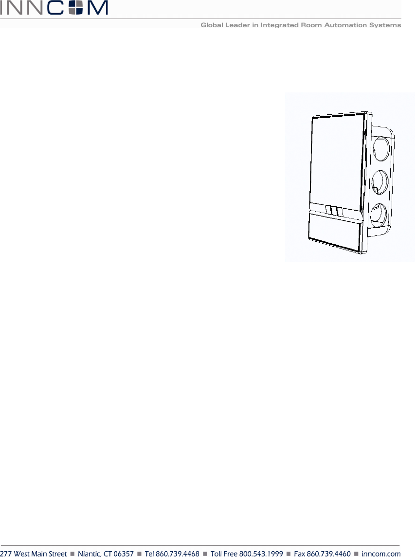
The K595 wall mounted passive infrared (PIR) motion detector (Figure 1) adds
occupancy sensing and peripheral-status reporting capability to INNCOM
integrated guestroom control systems. The K595 is designed with a sleek
screwless design that has the same look and feel as the INNCOM MODEVA
system. The K595 can be a key participant in an INNCOM Integrated Room
Automation System (IRAS) Deep Mesh network.
The K595, in conjunction with auxiliary input, a room controller, and an in-
room communication network, helps determine guestroom occupancy.
Occupancy sensing leads to better management of energy usage and security;
extends heating, ventilation, and air conditioning equipment life; enhances the
overall operating efficiency of the hotel; and improves guest satisfaction.
The K595 can also monitor and report on the status (e.g., open/closed) of other
devices within the guestroom (see Application below).
Features
• 120° view angle
• Flush screwless magnetic mounting
• Easy installation
• No maintenance
• Long battery life
• 2.4Ghz IEEE 802.15.4 compliant RF transceiver (CC2430 radio core)
• FCC Part 15b listed
Application
The K595 microprocessor-controlled PIR detects motion in a guestroom and reports it to the room controller.
Combined with information from other inputs (such as a lanai or window switch or a minibar), guestroom
occupancy can be determined and used for energy control or lighting decisions. Occupancy information may also
be signaled to Housekeeping using the corridor doorbell display or a floor-level terminal. The K595 can provide
an audit trail for Security, and it can be networked to the hotel’s central server.
On power up, the K595 will flash the LED for approximately two seconds as it configures itself using settings in
nonvolatile memory (see table below) and transmits a beacon frame (SAC_ALARM_K594_REPORT). The K595
will then go into Operation Mode, where it checks the auxiliary input, the motion detector, and the Bind switch
status. The K595 will process any actions instigated by those checks; after that (or if there is no action), it will
enter a low-power state (Sleep Mode) to conserve battery power. (See also the uCBL Engineering Manual.)
The K595 can also act as a minibar server if the I/O Map is so programmed. For details, see the uCBL Engineering
Manual, Sec. 2.4.2. Factory Default NVM Configuration.
Figure 1 K595

K 5 9 5 D a t a s h e e t P a g e | 2
Description Value
Room ID 65535
RF Channel 26
TX Power 0x5F (0dB)
P5 Address 189
P5 Channel 1
I/O Map 255
Installation
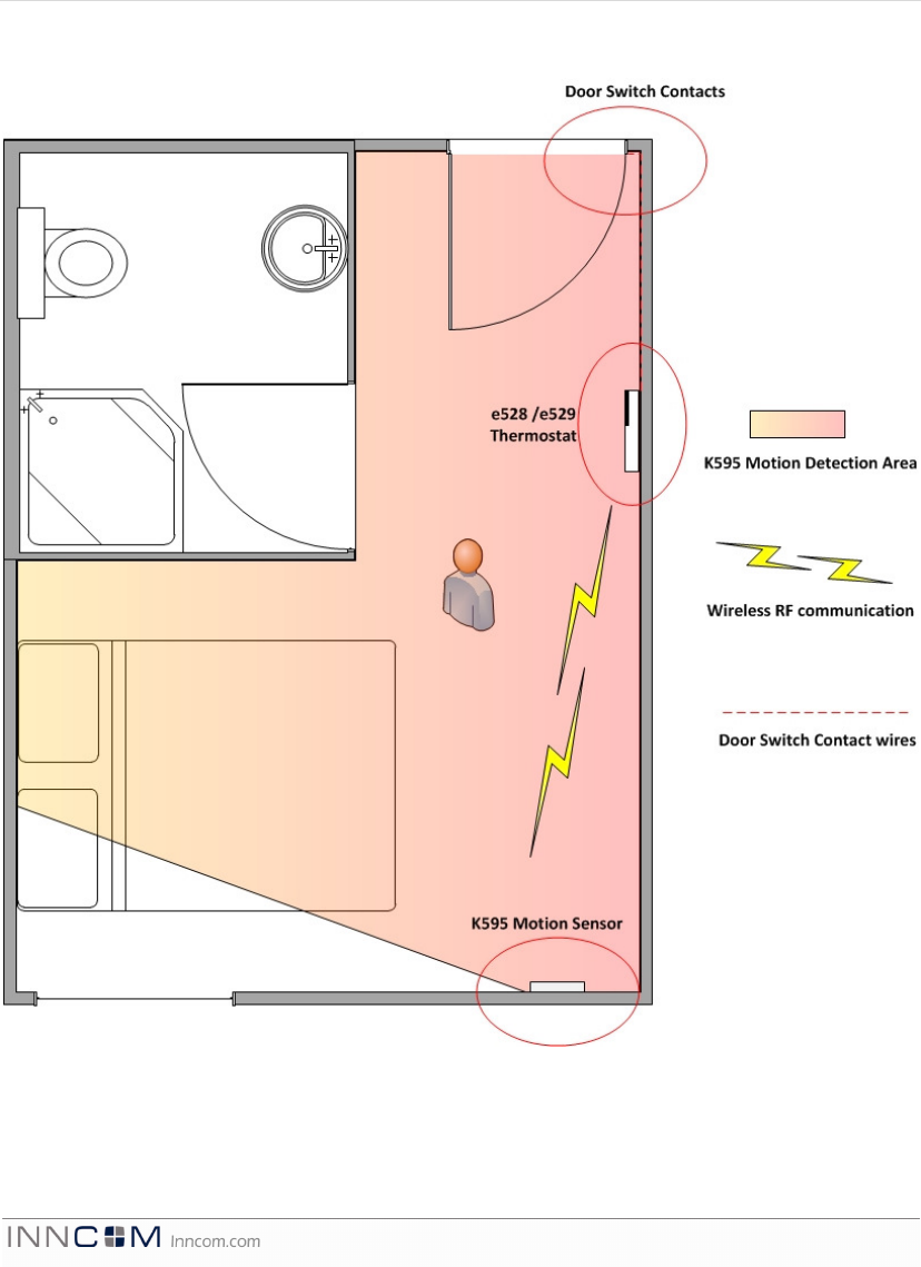
The individual guestroom design determines the K595’s installation location. Placement should provide
maximum room coverage by the PIR motion detector while maintaining RF communication between the device
and the e4 thermostat. Ideally, the K595 should be positioned on a wall in opposition to entrances and interior
doors (8ft. high, 0° angle, 0° pitch). The K595 PIR lens is pitched at a downward angle of 60° for optimal range
and minimized blind area below the unit. It should be positioned to view both the guestroom entry door and the
bed areas.
The K595 should be mounted within operational range of the e4 thermostat and any other devices it may
communicate with. Avoid possible sources of radio interference such as metallic boxes, WiFi access points,
microwave ovens, water pipes, and the like.
Refer to the K595 Installation Manual for detailed installation instruction.
Commissioning
Refer to the K595 Installation Manual or the uCBL Engineering Manual for commissioning instructions.
K 5 9 5 D a t a s h e e t P a g e | 3
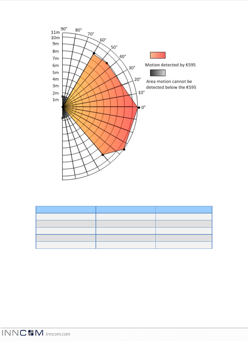
K595 PIR Range Chart:
Figure 2 K595 PIR Range
Table 1 K595 Range and View Angle Data
Angle Distance (Feet) Distance (Meters)
-60° 27ft 9.0m
-45° 27ft 9.0m
0° 33ft 11m
+45° 28.5ft 9.5m
+60° 33ft 11m
K 5 9 5 D a t a s h e e t P a g e | 4
Operational Coverage for K595
Figure 3 K595 Coverage
K 5 9 5 D a t a s h e e t P a g e | 5
PIR Specification
Parameter K595
No. of Fresnel beams 27
No. of curtain beams 9 + 5
Max. coverage See Figure 2
Sensitivity 0.5m–12m (1.64-40 ft.)
RF Specification
Parameter K595
RF Data Rate 250kbps
Antenna Type SMT
Indoor Range 70ft
Transmit Power 1mW (+0dBm)
Receive Sensitivity -94.6dBm
Frequency Band 2.4Ghz
Encryption AES-128
Protocol 802.15.4
Frequency Channels 11-26
Technical Specification
Parameter K595
Input voltage 4xAA Batteries
Battery Life 2.2 years
Operating temperature 0 °C to 60 °C (32 °F to 140 °F)
Storage temperature -20 °C to 60 °C (-4 °F to 140 °F)
Headers and Connectors
Header Connector
H1 Digital Input
H2 ICP
H3 Battery Input
Safety/Regulatory
Parameter Condition Status
FCC Part 15b
This equipment has been tested and found to comply with the limits for a Class B digital device,
pursuant to Part 15 of the FCC Rules. These limits are designed to provide reasonable protection against
harmful interference in a residential installation. This equipment generates uses and can radiate radio
frequency energy and, if not installed and used in accordance with the instructions, may cause harmful
interference to radio communications. However, there is no guarantee that interference will not occur
in a particular installation. If this equipment does cause harmful interference to radio or television
reception, which can be determined by turning the equipment off and on, the user is encouraged to try
to correct the interference by one of the following measures:
- Reorient or relocate the receiving antenna.
Deleted:
H2
K 5 9 5 D a t a s h e e t P a g e | 6
- Increase the separation between the equipment and receiver.
- Connect the equipment into an outlet on a circuit different from that
to which the receiver is connected.
- Consult the dealer or an experienced radio/TV technician for help.
This device complies with Part 15 of the FCC Rules. Operation is subject to the following two conditions:
(1) This device may not cause harmful interference, and (2) this device must accept any interference
received, including interference that may cause undesired operation.
Any changes or modifications not expressly approved by the party responsible for compliance could
void the user's authority to operate this equipment.
This device complies with Industry Canada licence-exempt RSS standard(s). Operation is subject to
the following two conditions: (1) this device may not cause interference, and (2) this device must
accept any interference, including interference that may cause undesired operation of the device.
Le présent appareil est conforme aux CNR d'Industrie Canada
applicables aux appareils radio exempts de licence.
L'exploitation est autorisée aux deux conditions suivantes : (1)
l'appareil ne doit pas produire de brouillage, et (2) l'utilisateur
de l'appareil doit accepter tout brouillage radioélectrique subi,
même si le brouillage est susceptible d'en compromettre le
fonctionnement.
re ordering Information
Part Number OPN Description
201-595 K595 Wall Mounted Motion Detector
References
Title Location
uCBL Device Engineering Manual v1.4 T:\Library\INNCOM Products\Systems\IRAS Reference\uCBL
K595 Installation Manual v1.0 T:\Library\INNCOM Documentation Library\Product
Documentation\Product Documentation Source
Document Revision History
Revision Date Issued Reason
0.1 02-May-2012 Initial Draft.
v1.0 07-May-2012 First release
Formatted Table
Deleted:
O
Deleted: