Honeywell 50016517 Modular Spread Spectrum Transmitter User Manual 34 XY 25 21 7 23 07
Honeywell International Inc. Modular Spread Spectrum Transmitter 34 XY 25 21 7 23 07
UserManual.wiki
>
Honeywell
>
50016517 User Manual
users manual
Navigation menu
Upload a User Manual
Namespaces
Wiki Guide
HTML
PDF
Info
Views
User Manual
Discussion / Help
Navigation
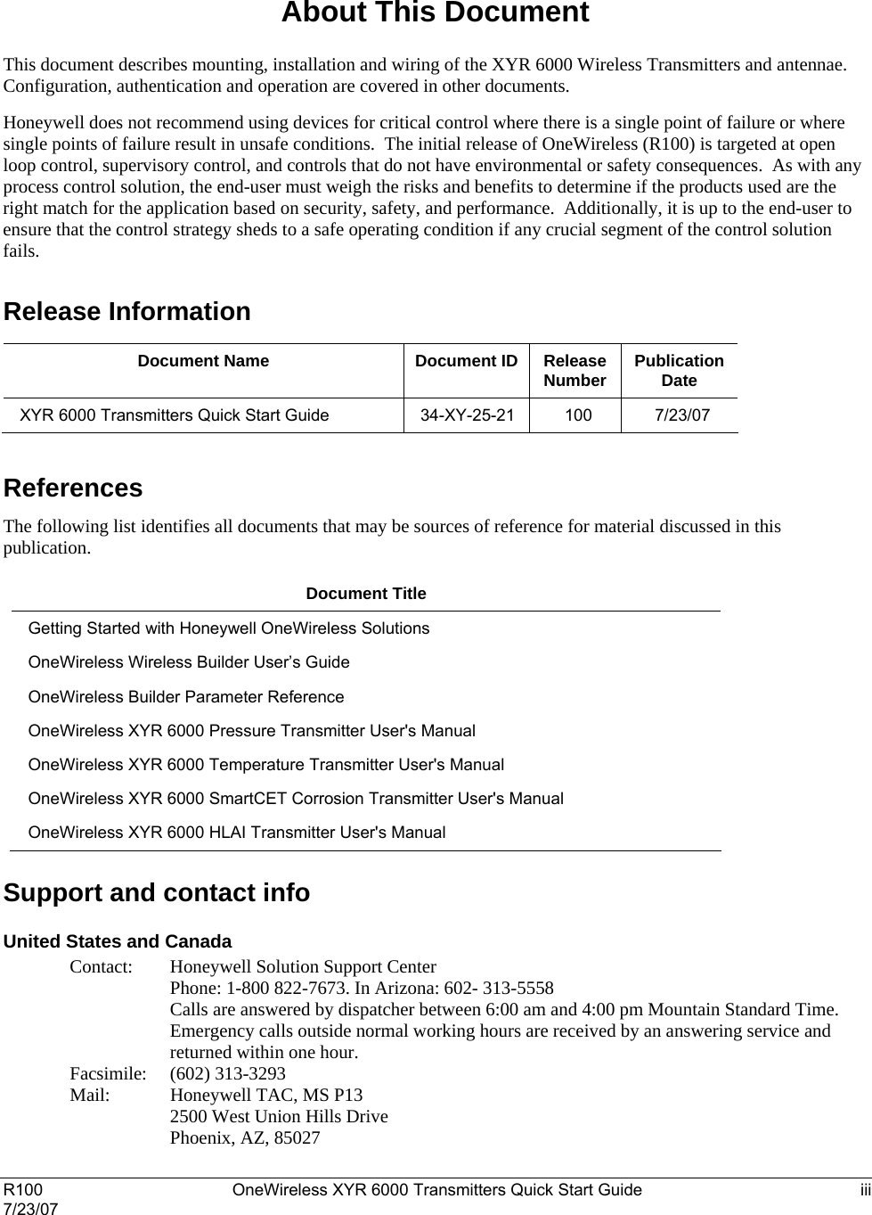

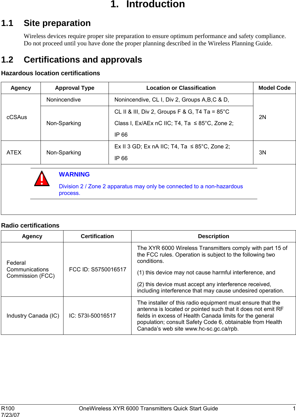
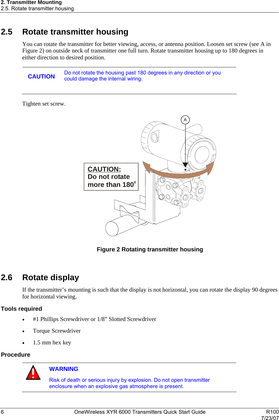
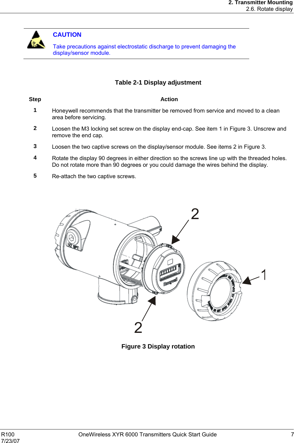

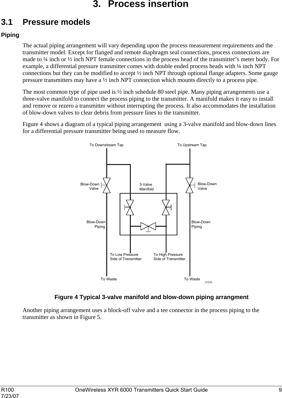
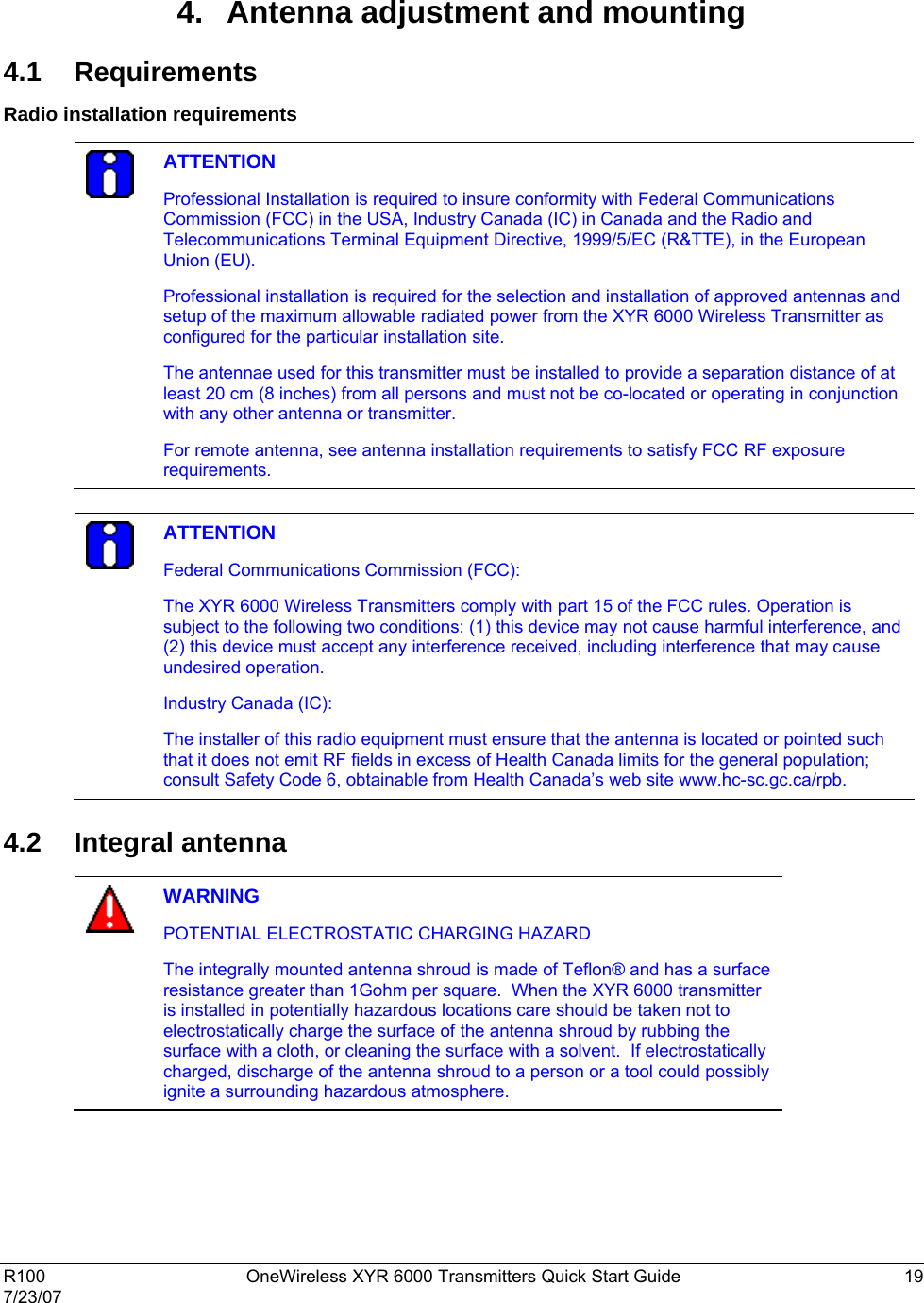
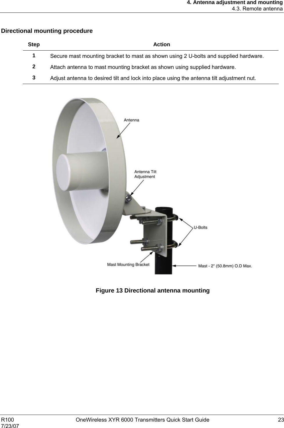
![3. Process insertion 3.1. Pressure models 10 OneWireless XYR 6000 Transmitters Quick Start Guide R100 7/23/07 Block-off Valve 1/2" NPTConnectionTank Wall Figure 5 Typical Arrangement for ½” NPT Process Connection Piping ATTENTION For liquid or steam, the piping should slope a minimum of 25.4 mm (1 inch) per 305 mm (1 foot). Slope the piping down towards the transmitter if the transmitter is below the process connection so the bubbles may rise back into the piping through the liquid. If the transmitter is located above the process connection, the piping should rise vertically above the transmitter; then slope down towards the flowline with a vent valve at the high point. For gas measurement, use a condensate leg and drain at the low point (freeze protection may be required here). CAUTION Property damage may result if operating temperature limits of transmitter are exceeded. Electronics housing must not exceed 85° C [185° F], meterbody temperature limit may be rated higher. Consult transmitter nameplate for meterbody temperature limits. To reduce the temperature of the process that comes into contact with the transmitter meter body, install impulse piping. As a general rule there is a 56 degree C drop (100 degrees F) in the temperature of the process for every foot (305 mm) of ½ inch uninsulated piping.](https://usermanual.wiki/Honeywell/50016517/User-Guide-824328-Page-20.png)