Honeywell 50016517 Modular Spread Spectrum Transmitter User Manual 34 XY 25 21 7 23 07
Honeywell International Inc. Modular Spread Spectrum Transmitter 34 XY 25 21 7 23 07
users manual

OneWireless
XYR 6000 Transmitters
Quick Start Guide
34-XY-25-21
R100
7/23/07
Release 100

ii OneWireless XYR 6000 Transmitters Quick Start Guide R100
7/23/07
Notices and Trademarks
Copyright 2007 by Honeywell International Inc.
Release 100 July 23, 2007
While this information is presented in good faith and believed to be accurate, Honeywell disclaims the implied
warranties of merchantability and fitness for a particular purpose and makes no express warranties except as may
be stated in its written agreement with and for its customers.
In no event is Honeywell liable to anyone for any indirect, special or consequential damages. The information and
specifications in this document are subject to change without notice.
Honeywell, PlantScape, Experion PKS, and TotalPlant are registered trademarks of Honeywell International Inc.
Other brand or product names are trademarks of their respective owners.
Honeywell International
Process Solutions
2500 West Union Hills
Phoenix, AZ 85027
1-800 343-0228

R100 OneWireless XYR 6000 Transmitters Quick Start Guide iii
7/23/07
About This Document
This document describes mounting, installation and wiring of the XYR 6000 Wireless Transmitters and antennae.
Configuration, authentication and operation are covered in other documents.
Honeywell does not recommend using devices for critical control where there is a single point of failure or where
single points of failure result in unsafe conditions. The initial release of OneWireless (R100) is targeted at open
loop control, supervisory control, and controls that do not have environmental or safety consequences. As with any
process control solution, the end-user must weigh the risks and benefits to determine if the products used are the
right match for the application based on security, safety, and performance. Additionally, it is up to the end-user to
ensure that the control strategy sheds to a safe operating condition if any crucial segment of the control solution
fails.
Release Information
Document Name Document ID Release
Number Publication
Date
XYR 6000 Transmitters Quick Start Guide 34-XY-25-21 100 7/23/07
References
The following list identifies all documents that may be sources of reference for material discussed in this
publication.
Document Title
Getting Started with Honeywell OneWireless Solutions
OneWireless Wireless Builder User’s Guide
OneWireless Builder Parameter Reference
OneWireless XYR 6000 Pressure Transmitter User's Manual
OneWireless XYR 6000 Temperature Transmitter User's Manual
OneWireless XYR 6000 SmartCET Corrosion Transmitter User's Manual
OneWireless XYR 6000 HLAI Transmitter User's Manual
Support and contact info
United States and Canada
Contact: Honeywell Solution Support Center
Phone: 1-800 822-7673. In Arizona: 602- 313-5558
Calls are answered by dispatcher between 6:00 am and 4:00 pm Mountain Standard Time.
Emergency calls outside normal working hours are received by an answering service and
returned within one hour.
Facsimile: (602) 313-3293
Mail: Honeywell TAC, MS P13
2500 West Union Hills Drive
Phoenix, AZ, 85027

iv OneWireless XYR 6000 Transmitters Quick Start Guide R100
7/23/07
Europe
Contact: Honeywell TAC-EMEA
Phone: +32-2-728-2732
Facsimile: +32-2-728-2696
Mail: TAC-BE02
Hermes Plaza
Hermeslaan, 1H
B-1831 Diegem, Belgium
Pacific
Contact: Honeywell Global TAC – Pacific
Phone: 1300-300-4822 (toll free within Australia)
+61-8-9362-9559 (outside Australia)
Facsimile: +61-8-9362-9564
Mail: Honeywell Limited Australia
5 Kitchener Way
Burswood 6100, Western Australia
Email: GTAC@honeywell.com
India
Contact: Honeywell Global TAC – India
Phone: +91-20- 6603-9400
Facsimile: +91-20- 6603-9800
Mail: Honeywell Automation India Ltd.
56 and 57, Hadapsar Industrial Estate
Hadapsar, Pune –411 013, India
Email: Global-TAC-India@honeywell.com
Korea
Contact: Honeywell Global TAC – Korea
Phone: +82-2-799-6317
+82-11-9227-6324
Facsimile: +82-2-792-9015
Mail: Honeywell Co., Ltd
17F, Kikje Center B/D,
191, Hangangro-2Ga
Yongsan-gu, Seoul, 140-702, Korea
Email: Global-TAC-Korea@honeywell.com
People’s Republic of China
Contact: Honeywell Global TAC – China
Phone: +86- 21-5257-4568
Mail: Honeywell (China) Co., Ltd
33/F, Tower A, City Center, 100 Zunyi Rd.
Shanghai 200051, People’s Republic of China
Email: Global-TAC-China@honeywell.com

R100 OneWireless XYR 6000 Transmitters Quick Start Guide v
7/23/07
Singapore
Contact: Honeywell Global TAC – South East Asia
Phone: +65-6580-3500
Facsimile: +65-6580-3501
+65-6445-3033
Mail: Honeywell Private Limited
Honeywell Building
17, Changi Business Park Central 1
Singapore 486073
Email: GTAC-SEA@honeywell.com
Taiwan
Contact: Honeywell Global TAC – Taiwan
Phone: +886- 7- 536-2567
Facsimile: +886-7-536-2039
Mail: Honeywell Taiwan Ltd.
17F-1, No. 260, Jhongshan 2nd Road.
Cianjhen District
Kaohsiung, Taiwan, ROC
Email: Global-TAC-Taiwan@honeywell.com
Japan
Contact: Honeywell Global TAC – Japan
Phone: +81-3-6730-7160
Facsimile: +81-3-6730-7228
Mail: Honeywell Japan Inc.
New Pier Takeshiba, South Tower Building,
20th Floor, 1-16-1 Kaigan, Minato-ku,
Tokyo 105-0022, Japan
Email: Global-TAC-JapanJA25@honeywell.com
World Wide Web
Honeywell Solution Support Online:
http://www.honeywell.com/ps
Elsewhere
Call your nearest Honeywell office.
Training Classes
Honeywell Automation College:
http://www.automationcollege.com
vi OneWireless XYR 6000 Transmitters Quick Start Guide R100
7/23/07
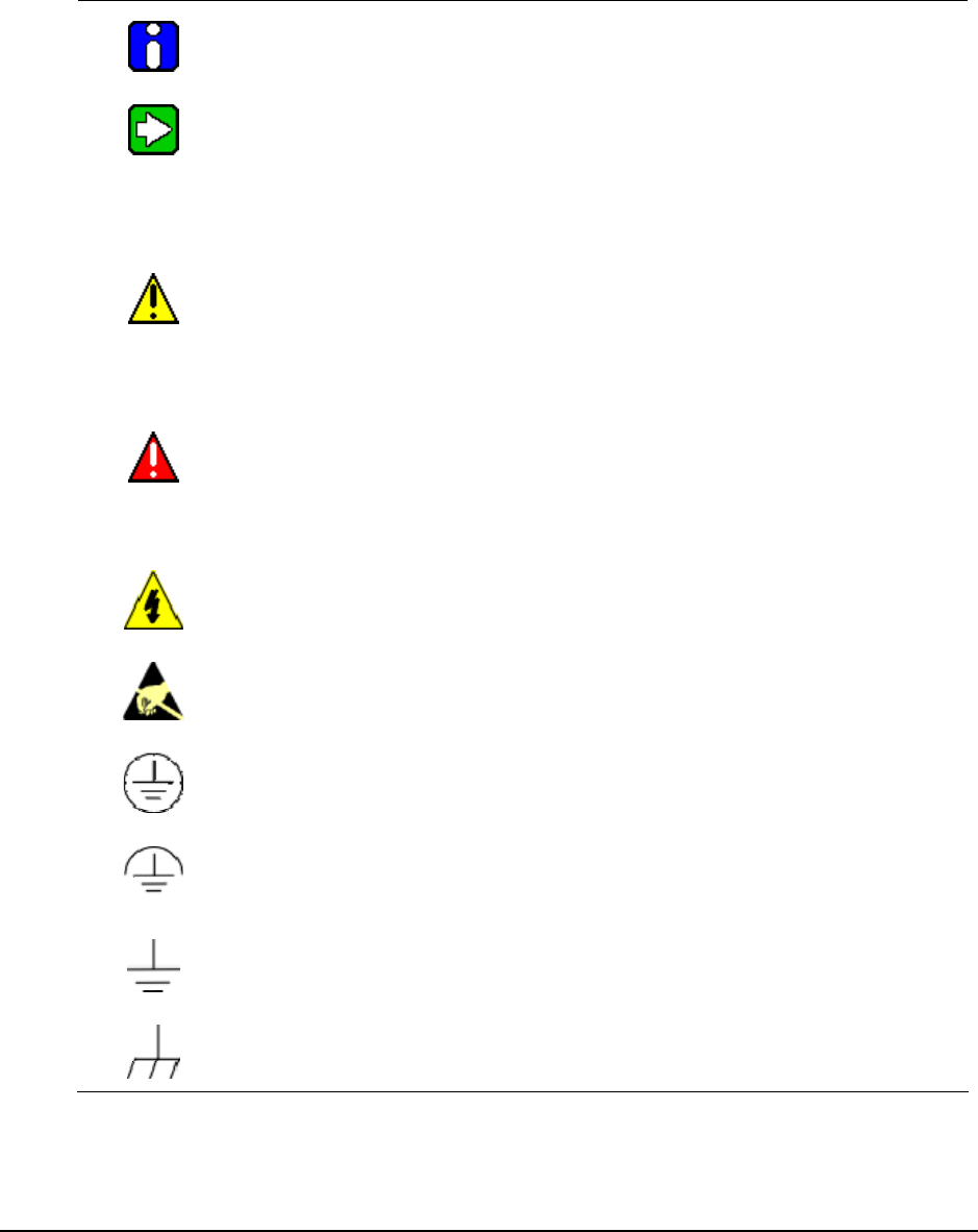
Symbol Definitions
The following table lists those symbols used in this document to denote certain conditions.
Symbol Definition
ATTENTION: Identifies information that requires special consideration.
TIP: Identifies advice or hints for the user, often in terms of performing a task.
CAUTION
Indicates a situation which, if not avoided, may result in equipment or work (data) on
the system being damaged or lost, or may result in the inability to properly operate
the process.
CAUTION: Indicates a potentially hazardous situation which, if not avoided, may
result in minor or moderate injury. It may also be used to alert against unsafe
practices.
CAUTION symbol on the equipment refers the user to the product manual for
additional information. The symbol appears next to required information in the
manual.
WARNING: Indicates a potentially hazardous situation, which, if not avoided, could
result in serious injury or death.
WARNING symbol on the equipment refers the user to the product manual for
additional information. The symbol appears next to required information in the
manual.
WARNING, Risk of electrical shock: Potential shock hazard where HAZARDOUS
LIVE voltages greater than 30 Vrms, 42.4 Vpeak, or 60 VDC may be accessible.
ESD HAZARD: Danger of an electro-static discharge to which equipment may be
sensitive. Observe precautions for handling electrostatic sensitive devices.
Protective Earth (PE) terminal: Provided for connection of the protective earth
(green or green/yellow) supply system conductor.
Functional earth terminal: Used for non-safety purposes such as noise immunity
improvement. NOTE: This connection shall be bonded to Protective Earth at the
source of supply in accordance with national local electrical code requirements.
Earth Ground: Functional earth connection. NOTE: This connection shall be
bonded to Protective Earth at the source of supply in accordance with national and
local electrical code requirements.
Chassis Ground: Identifies a connection to the chassis or frame of the equipment
shall be bonded to Protective Earth at the source of supply in accordance with
national and local electrical code requirements.

R100 OneWireless XYR 6000 Transmitters Quick Start Guide vii
7/23/07
Contents
Support and contact info........................................................................................................................iii
1. INTRODUCTION....................................................................................................1
1.1 Site preparation.............................................................................................................................1
1.2 Certifications and approvals........................................................................................................1
Hazardous location certifications ............................................................................................................................1
Radio certifications .................................................................................................................................................1
Approval ratings .....................................................................................................................................................2
2. TRANSMITTER MOUNTING .................................................................................3
2.1 Weight ............................................................................................................................................3
2.2 Dimensions....................................................................................................................................3
2.3 Transmitter location......................................................................................................................4
Pressure models.....................................................................................................................................................4
2.4 Bracket mounting..........................................................................................................................4
Attach bracket to pipe.............................................................................................................................................4
Attach transmitter to bracket...................................................................................................................................5
2.5 Rotate transmitter housing ..........................................................................................................6
2.6 Rotate display................................................................................................................................6
Tools required ........................................................................................................................................................6
Procedure...............................................................................................................................................................6
3. PROCESS INSERTION .........................................................................................9
3.1 Pressure models ...........................................................................................................................9
Piping .....................................................................................................................................................................9
Process connections ............................................................................................................................................11
General piping guidelines .....................................................................................................................................11
3.2 Temperature models...................................................................................................................12
Insert probe into process ......................................................................................................................................12
Integral probe wiring .............................................................................................................................................12
Remote probe wiring ............................................................................................................................................12
3.3 HLAI models ................................................................................................................................13
Connect wiring......................................................................................................................................................13
3.4 Corrosion models........................................................................................................................14
Probe mounting locations .....................................................................................................................................14
Probe installation..................................................................................................................................................17
Connect wiring......................................................................................................................................................18
4. ANTENNA ADJUSTMENT AND MOUNTING .....................................................19
4.1 Requirements ..............................................................................................................................19
Radio installation requirements ............................................................................................................................19
4.2 Integral antenna...........................................................................................................................19
Elbow....................................................................................................................................................................20

Contents
Symbol Definitions
viii OneWireless XYR 6000 Transmitters Quick Start Guide R100
7/23/07
Straight................................................................................................................................................................. 20
4.3 Remote antenna ..........................................................................................................................21
Outdoor installation warnings............................................................................................................................... 21
Directional mounting procedure ........................................................................................................................... 23
Omnidirectional mounting procedure ................................................................................................................... 24
Connect antenna to transmitter............................................................................................................................ 24
5. START UP ........................................................................................................... 25
5.1 Connect batteries........................................................................................................................25
Display sequence................................................................................................................................................. 26
Authentication ...................................................................................................................................................... 26
6. CSA CERTIFIED DIVISION 2 / ZONE 2 INSTALLATION DRAWINGS .............. 27

Contents
Tables
R100 OneWireless XYR 6000 Transmitters Quick Start Guide ix
7/23/07
Tables
Table 2-1 Display adjustment ........................................................................................................................7

Contents
Figures
x OneWireless XYR 6000 Transmitters Quick Start Guide R100
7/23/07
Figures
Figure 1 Common bracket orientations .........................................................................................................4
Figure 2 Rotating transmitter housing ...........................................................................................................6
Figure 3 Display rotation................................................................................................................................7
Figure 4 Typical 3-valve manifold and blow-down piping arrangment ..........................................................9
Figure 5 Typical Arrangement for ½” NPT Process Connection Piping ......................................................10
Figure 6 Temperature probes......................................................................................................................12
Figure 7 HLAI connection ............................................................................................................................13
Figure 8 Voltage input wiring .......................................................................................................................13
Figure 9 Current input wiring .......................................................................................................................13
Figure 10 Corrosion transmitter with remote probe.....................................................................................18
Figure 11 Elbow antenna adjustment ..........................................................................................................20
Figure 12 Integral straight antenna..............................................................................................................20
Figure 13 Directional antenna mounting......................................................................................................23
Figure 14 Omnidirection antenna mounting ................................................................................................24
Figure 15 Battery assembly.........................................................................................................................26
R100 OneWireless XYR 6000 Transmitters Quick Start Guide 1
7/23/07
1. Introduction
1.1 Site preparation
Wireless devices require proper site preparation to ensure optimum performance and safety compliance.
Do not proceed until you have done the proper planning described in the Wireless Planning Guide.
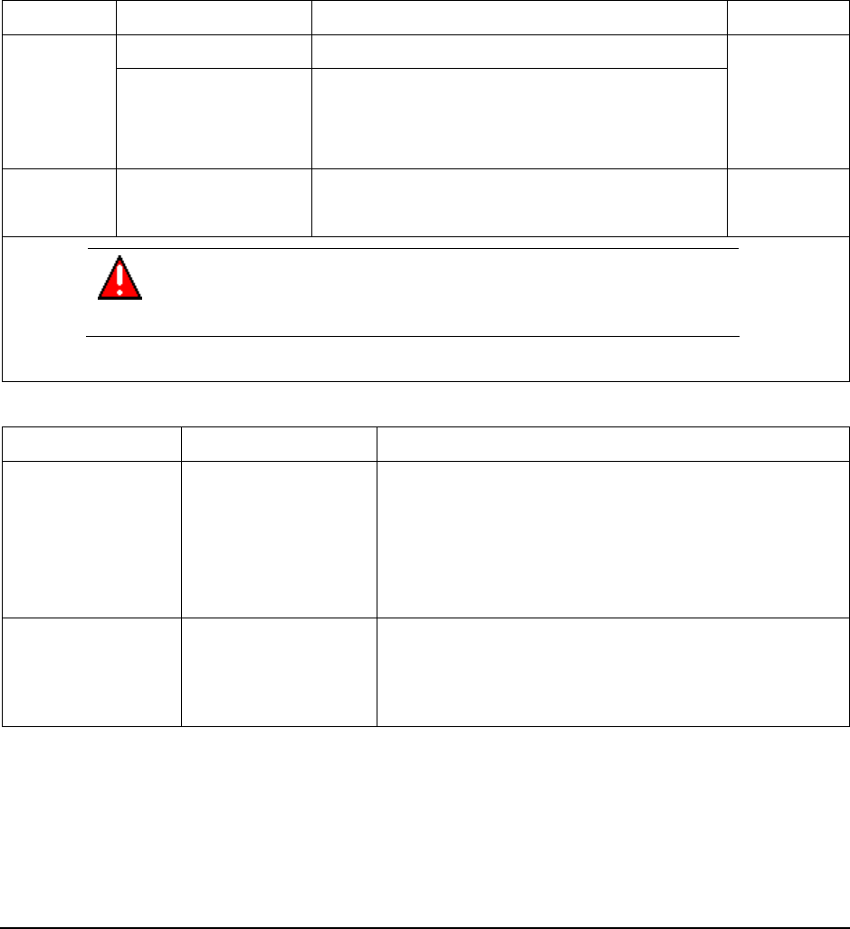
1.2 Certifications and approvals
Hazardous location certifications
Agency Approval Type Location or Classification Model Code
Nonincendive Nonincendive, CL I, Div 2, Groups A,B,C & D,
cCSAus
Non-Sparking
CL II & III, Div 2, Groups F & G, T4 Ta = 85°C
Class I, Ex/AEx nC IIC; T4, Ta ≤ 85°C, Zone 2;
IP 66
2N
ATEX Non-Sparking
Ex II 3 GD; Ex nA IIC; T4, Ta ≤ 85°C, Zone 2;
IP 66
3N
WARNING
Division 2 / Zone 2 apparatus may only be connected to a non-hazardous
process.
Radio certifications
Agency Certification Description
Federal
Communications
Commission (FCC)
FCC ID: S5750016517
The XYR 6000 Wireless Transmitters comply with part 15 of
the FCC rules. Operation is subject to the following two
conditions.
(1) this device may not cause harmful interference, and
(2) this device must accept any interference received,
including interference that may cause undesired operation.
Industry Canada (IC) IC: 573I-50016517
The installer of this radio equipment must ensure that the
antenna is located or pointed such that it does not emit RF
fields in excess of Health Canada limits for the general
population; consult Safety Code 6, obtainable from Health
Canada’s web site www.hc-sc.gc.ca/rpb.

1. Introduction
1.2. Certifications and approvals
2 OneWireless XYR 6000 Transmitters Quick Start Guide R100
7/23/07
Approval ratings
Temperature transmitter Approval / Item Ratings / Description Pressure
Transmitter
Integral
Probe
Remote
Inputs
High Level
Analog
Input HLAI
Corrosion
Transmitter
w/Remote
Probe
Nonincendive* Nonincendive, CL I, Div 2, Groups A,B,C & D,
CL II & III, Div 2, Groups F & G, T4 Ta = 85°C;
Non-Sparking CL I, Ex/AEx nA IIC T4; Ta = 85°C, Zone 2
X X X X X
Ex II 3 GD, EEx nA IIC T4; Ta = 85°C, Zone 2 X X X X X
Process
Connections
WARNING – Division 2 / Zone 2 apparatus
may only be connected to a non-hazardous
process.
X n/a n/a n/a X
Max Process Temperature +125°C +85°C Sensor Rating n/a n/a
Ambient Temperature Limits Cold: –40°C –40°C –40°C –40°C –30°C
Temperature
Limits
Ambient Temperature Limits Hot: +85°C +85°C +85°C +85°C +85°C
4X / IP 66/67 X n/a X X X
Enclosure
Type*
4 / IP 66 n/a X n/a n/a n/a
CRN Canadian Registration Number X X n/a n/a X
Entry Plugs 1/2 NPT or M20 as required, quantity required 2 2 1 1 1
Conduit (Explosionproof Not Required) n/a X X X n/a
Field Wiring
(Supplied by
others) Cable Gland* n/a X X X X*
*Class II and III installations and for Type 4X/IP66 applications require that all cable and unused entires be sealed with an NRTL
listed cable gland or seal fitting. Cable glands and seal fittings are not supplied by Honeywell.
R100 OneWireless XYR 6000 Transmitters Quick Start Guide 3
7/23/07
2. Transmitter Mounting
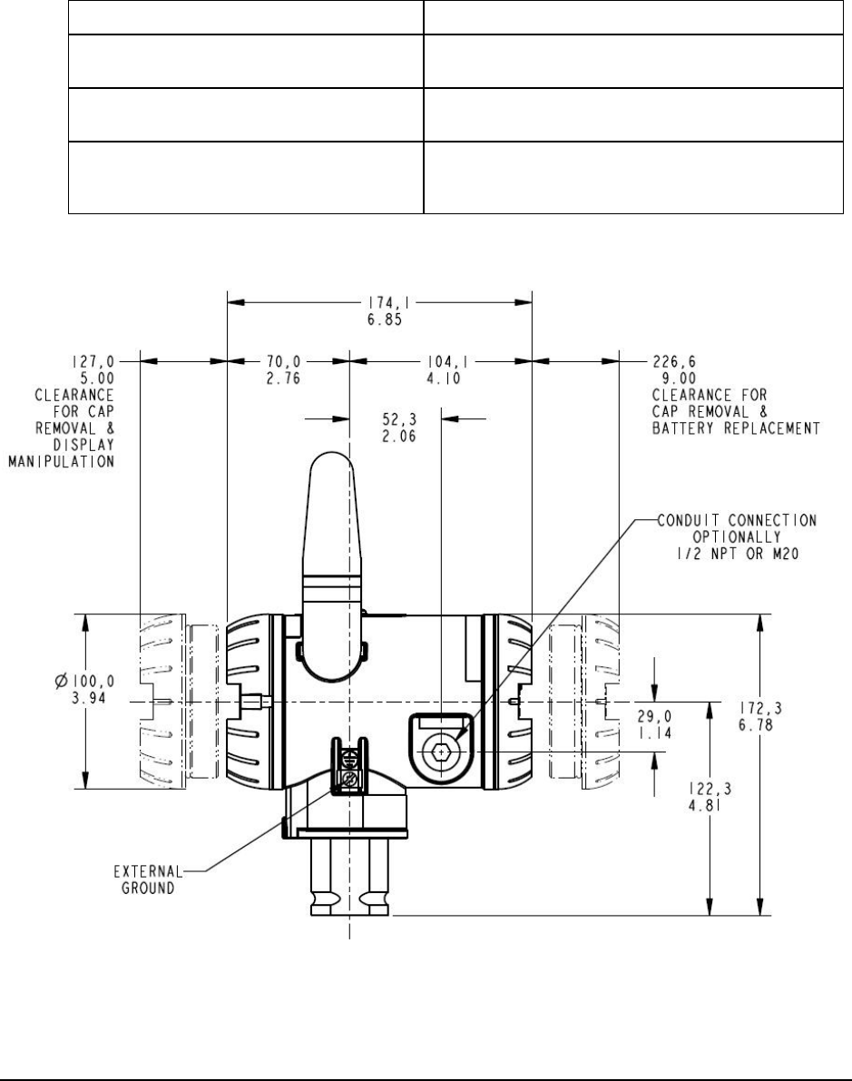
2.1 Weight
Transmitter model Weight
STDW9xx
STGW9x4
11 lbs (5 kg)
STGW9xL
STAW94L
7 lbs (3.2 kg)
STIW400
STTW400
CETW6000M
6 lbs (2.7 kg)
2.2 Dimensions
2. Transmitter Mounting
2.3. Transmitter location
4 OneWireless XYR 6000 Transmitters Quick Start Guide R100
7/23/07
2.3 Transmitter location
Pressure models
Process Suggested location Explanation
Gases Above the gas line The condensate drains away from the
transmitter.
Liquids • Below but close to the
elevation of the process
connection.
• Level with or above the
process connection.
• This minimizes the static head
effect of the condensate.
• This requires a siphon to protect
the transmitter from process
steam. The siphon retains water as
a “fill fluid.”
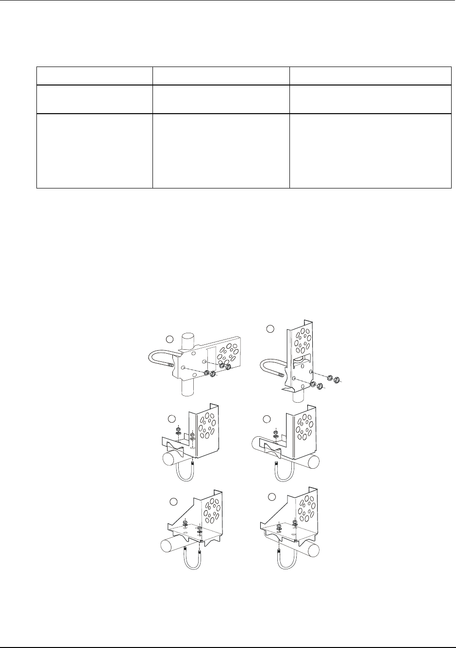
2.4 Bracket mounting
Attach bracket to pipe
Figure 1 shows some commonly used bracket and pipe orientations. Not all possibilities are shown; you
can use any bracket (flat or angle) and orientation (parallel or transverse) to get the desired transmitter
positioning.
Position bracket on 2-inch (50.8 mm) pipe and install “U” bolt around pipe and through holes in bracket.
Secure with nuts and lockwashers provided.
B
E
F
CD
A
Figure 1 Common bracket orientations
2. Transmitter Mounting
2.4. Bracket mounting
R100 OneWireless XYR 6000 Transmitters Quick Start Guide 5
7/23/07
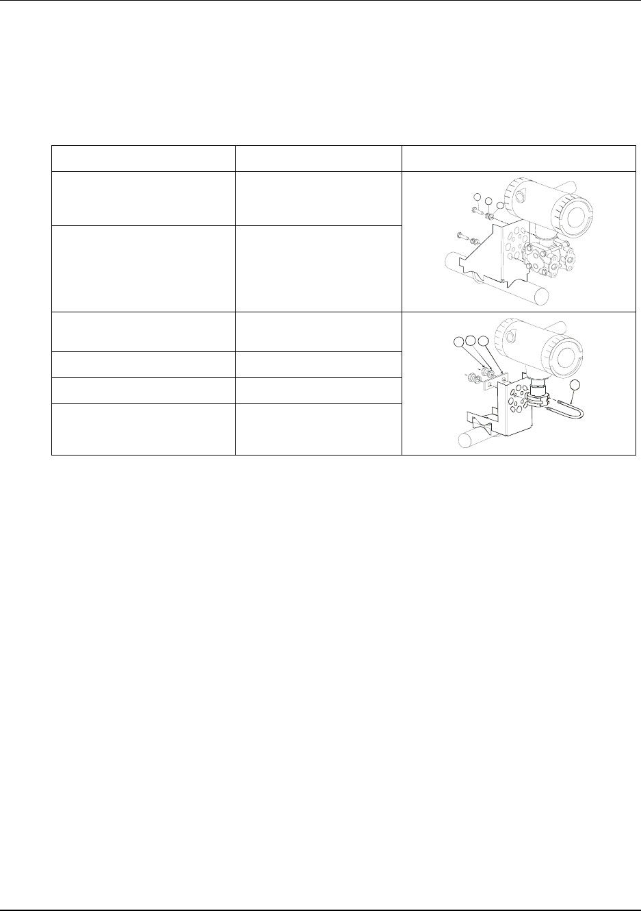
Attach transmitter to bracket
Align appropriate mounting holes in transmitter with holes in bracket and secure the transmitter to the
bracket with bolts and washers provided.
If the meter body is hexagonal, you must use the additional bracket supplied. If meter body is round,
discard the bracket.
Transmitter type Attachment to bracket Example
DP type with double-ended
process heads and/or remote
seals
Alternate mounting holes
in end of heads.
Dual head GP Mounting holes in end of
process head
A
B
C
In-line GP and AP (LGP
model)
Smaller “U” bolt.
Temperature Smaller “U” bolt.
High Level AI Smaller “U” bolt.
Corrosion Smaller “U” bolt.
A
B
C
D
2. Transmitter Mounting
2.5. Rotate transmitter housing
6 OneWireless XYR 6000 Transmitters Quick Start Guide R100
7/23/07
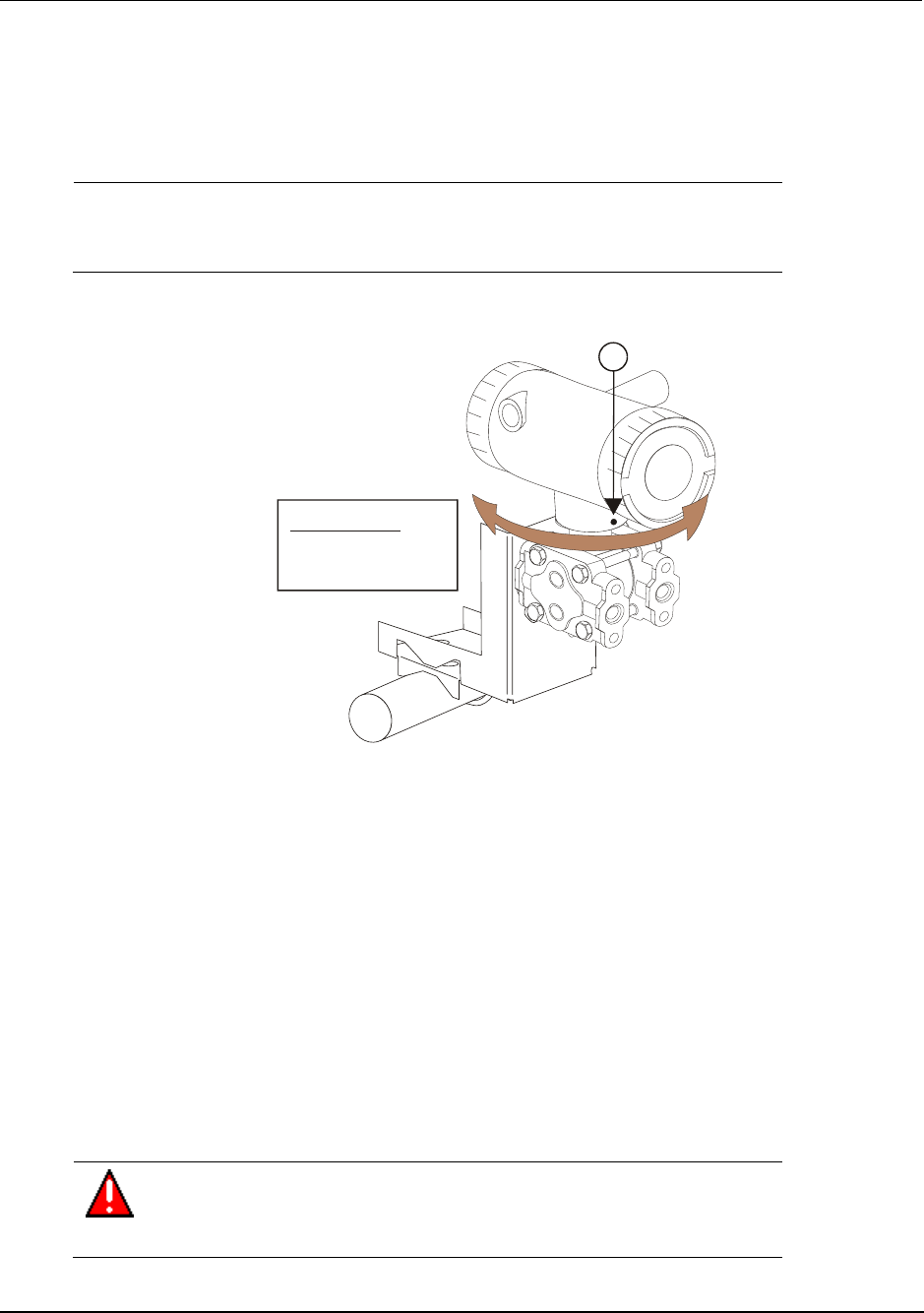
2.5 Rotate transmitter housing
You can rotate the transmitter for better viewing, access, or antenna position. Loosen set screw (see A in
Figure 2) on outside neck of transmitter one full turn. Rotate transmitter housing up to 180 degrees in
either direction to desired position.
CAUTION
Do not rotate the housing past 180 degrees in any direction or you
could damage the internal wiring.
Tighten set screw.
CAUTION:
Do not rotate
more than 180
0
A
Figure 2 Rotating transmitter housing
2.6 Rotate display
If the transmitter’s mounting is such that the display is not horizontal, you can rotate the display 90 degrees
for horizontal viewing.
Tools required
• #1 Phillips Screwdriver or 1/8” Slotted Screwdriver
• Torque Screwdriver
• 1.5 mm hex key
Procedure
WARNING
Risk of death or serious injury by explosion. Do not open transmitter
enclosure when an explosive gas atmosphere is present.
2. Transmitter Mounting
2.6. Rotate display
R100 OneWireless XYR 6000 Transmitters Quick Start Guide 7
7/23/07
CAUTION
Take precautions against electrostatic discharge to prevent damaging the
display/sensor module.
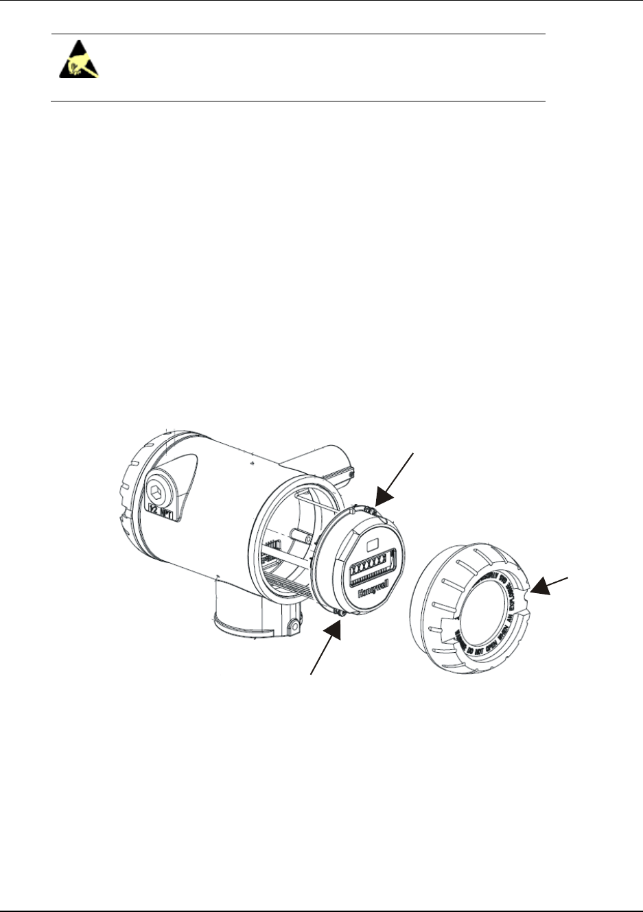
Table 2-1 Display adjustment
Step Action
1 Honeywell recommends that the transmitter be removed from service and moved to a clean
area before servicing.
2 Loosen the M3 locking set screw on the display end-cap. See item 1 in Figure 3. Unscrew and
remove the end cap.
3 Loosen the two captive screws on the display/sensor module. See items 2 in Figure 3.
4 Rotate the display 90 degrees in either direction so the screws line up with the threaded holes.
Do not rotate more than 90 degrees or you could damage the wires behind the display.
5 Re-attach the two captive screws.
1
2
2
Figure 3 Display rotation

2. Transmitter Mounting
2.6. Rotate display
8 OneWireless XYR 6000 Transmitters Quick Start Guide R100
7/23/07
R100 OneWireless XYR 6000 Transmitters Quick Start Guide 9
7/23/07
3. Process insertion
3.1 Pressure models
Piping
The actual piping arrangement will vary depending upon the process measurement requirements and the
transmitter model. Except for flanged and remote diaphragm seal connections, process connections are
made to ¼ inch or ½ inch NPT female connections in the process head of the transmitter’s meter body. For
example, a differential pressure transmitter comes with double ended process heads with ¼ inch NPT
connections but they can be modified to accept ½ inch NPT through optional flange adapters. Some gauge
pressure transmitters may have a ½ inch NPT connection which mounts directly to a process pipe.
The most common type of pipe used is ½ inch schedule 80 steel pipe. Many piping arrangements use a
three-valve manifold to connect the process piping to the transmitter. A manifold makes it easy to install
and remove or rezero a transmitter without interrupting the process. It also accommodates the installation
of blow-down valves to clear debris from pressure lines to the transmitter.
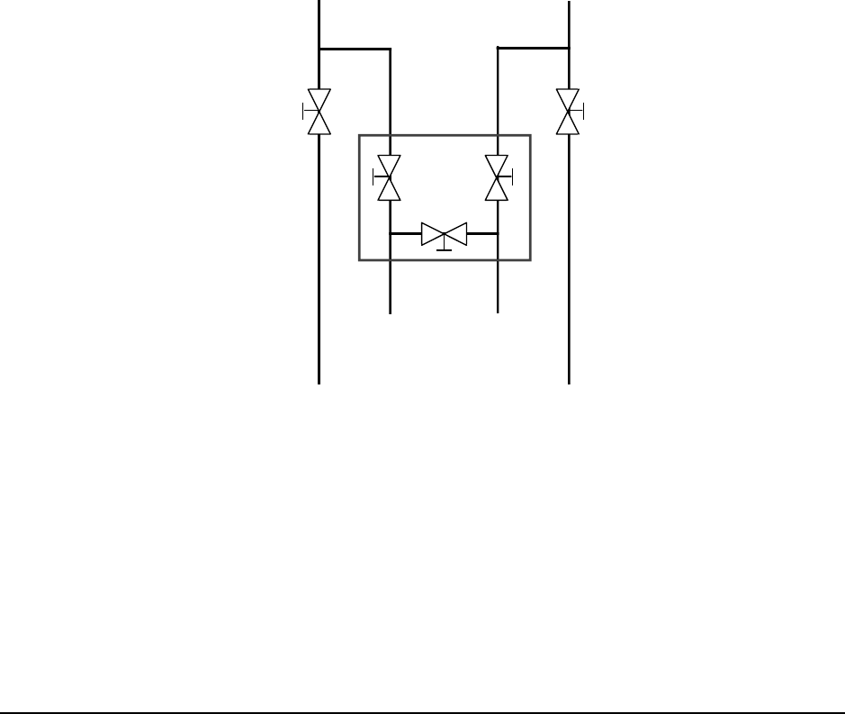
Figure 4 shows a diagram of a typical piping arrangement using a 3-valve manifold and blow-down lines
for a differential pressure transmitter being used to measure flow.
Blow-Down
Valve
3-Valve
Manifold
To Upstream TapTo Downstream Tap
To Low Pressure
Side of Transmitter
To High Pressure
Side of Transmitter
Blow-Down
Valve
Blow-Down
Piping
To WasteTo Waste
Blow-Down
Piping
21010
Figure 4 Typical 3-valve manifold and blow-down piping arrangment
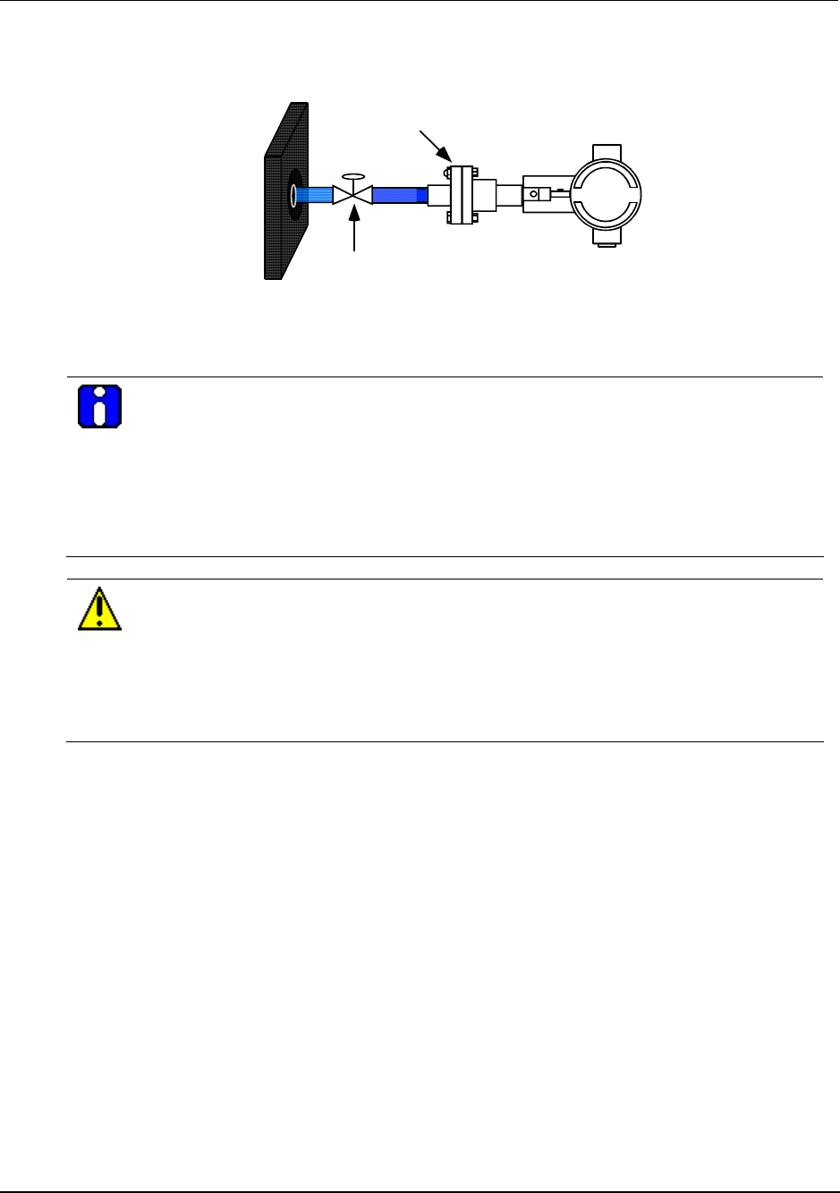
Another piping arrangement uses a block-off valve and a tee connector in the process piping to the
transmitter as shown in Figure 5.
3. Process insertion
3.1. Pressure models
10 OneWireless XYR 6000 Transmitters Quick Start Guide R100
7/23/07
Block-off Valve
1/2" NPT
Connection
Tank Wall
Figure 5 Typical Arrangement for ½” NPT Process Connection Piping
ATTENTION
For liquid or steam, the piping should slope a minimum of 25.4 mm (1 inch) per 305 mm (1
foot). Slope the piping down towards the transmitter if the transmitter is below the process
connection so the bubbles may rise back into the piping through the liquid. If the transmitter is
located above the process connection, the piping should rise vertically above the transmitter;
then slope down towards the flowline with a vent valve at the high point. For gas
measurement, use a condensate leg and drain at the low point (freeze protection may be
required here).
CAUTION
Property damage may result if operating temperature limits of transmitter are exceeded.
Electronics housing must not exceed 85° C [185° F], meterbody temperature limit may be
rated higher. Consult transmitter nameplate for meterbody temperature limits. To reduce
the temperature of the process that comes into contact with the transmitter meter body, install
impulse piping. As a general rule there is a 56 degree C drop (100 degrees F) in the
temperature of the process for every foot (305 mm) of ½ inch uninsulated piping.

3. Process insertion
3.1. Pressure models
R100 OneWireless XYR 6000 Transmitters Quick Start Guide 11
7/23/07
Process connections
Transmitter Type Process Connection
Differential Pressure Process heads with ¼ inch NPT female connection
Flange adapters and manifolds with ½ inch female connection are
optional
Gauge Pressure Process head with ½ inch NPT female connection
In-line ½ inch NPT female connection
In-line ½ inch NPT male
9/16 Aminco
DIN19213n
Process heads with ¼ inch NPT female connection
Flange adapters and manifolds with ½ inch female connections are
optional
Absolute Pressure Process head with ½ inch NPT female connection
In-line ½-inch NPT male
9/16 Aminco
DIN19213n
General piping guidelines
When measuring fluids containing suspended solids, install permanent valves at regular intervals to blow-
down piping.
Blow-down all lines on new installations with compressed air or steam and flush them with process fluids
(where possible) before connecting these lines to the transmitter’s meter body.
Be sure all the valves in the blow-down lines are closed tight after the initial blow-down procedure and
each maintenance procedure after that.
3. Process insertion
3.2. Temperature models
12 OneWireless XYR 6000 Transmitters Quick Start Guide R100
7/23/07
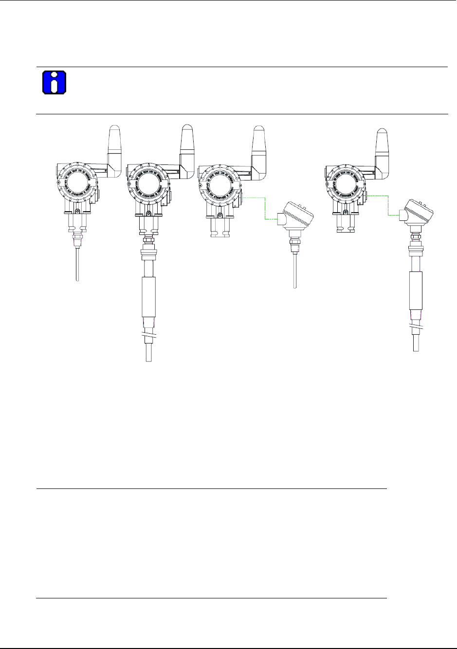
3.2 Temperature models
Insert probe into process
ATTENTION
It is your responsibility to supply a suitable sealing method or gasket and mounting hardware
for the probe’s service conditions.
Inte g ra l
Ri g i d Inte g ra l
Sp r i n g
loaded
Re m o t e
Ri g i d
Re m o t e
Sp r i n g
loaded
Figure 6 Temperature probes
Integral probe wiring
The integral probe is pre-wired to the transmitter at the factory.
Remote probe wiring
Step Action
1 See Figure 6. Open the transmitter’s rear end cap (opposite end from
display).
2 Open the cable gland (on right side below antenna).
3 Feed wiring (6 to 8 mm allowed diameter) through the cable gland and
connect to terminal block. See page 27 for terminal connections.
4 Plug battery connector into batteries.
5 Close rear end cap and cable gland.
3. Process insertion
3.3. HLAI models
R100 OneWireless XYR 6000 Transmitters Quick Start Guide 13
7/23/07
3.3 HLAI models
Connect wiring
Step Action
1 See Figure 7. HLAI transmitter is shown at left. Open the rear end cap
(opposite end from display).
2 Open the cable gland (on right side below antenna).
3 Feed wiring (allowed diameter 6 to 8 mm) from other transmitter through the
cable gland and connect to terminal block using either voltage or current but
not both. See Figure 8 or Figure 9. For hazardous locations see page 27.
4 Plug battery connector into batteries.
5 Close rear end cap and cable gland.
Figure 7 HLAI connection
1
2
3
5
4
6
+
-
0-5V
1-5V
+
-
1
2
3
5
4
6
+
-
0-5V
1-5V
+
-
Figure 8 Voltage input wiring
1
2
3
5
4
6
+
-
0-20 mA
4-20mA
+
-
1
2
3
5
4
6
+
-
0-20 mA
4-20mA
1
2
3
5
4
6
+
-
0-20 mA
4-20mA
+
-
Figure 9 Current input wiring
3. Process insertion
3.4. Corrosion models
14 OneWireless XYR 6000 Transmitters Quick Start Guide R100
7/23/07
3.4 Corrosion models
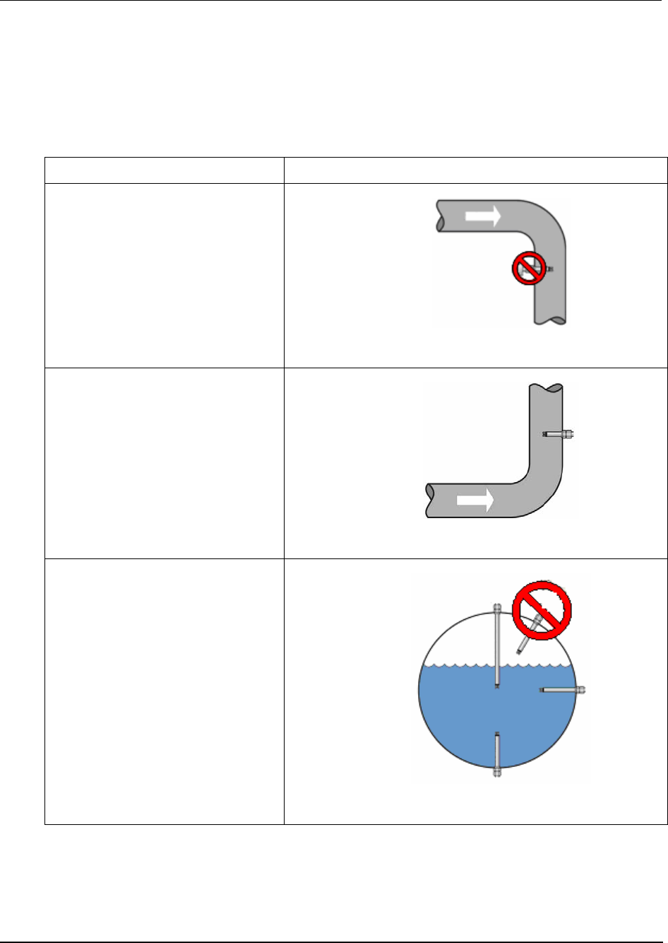
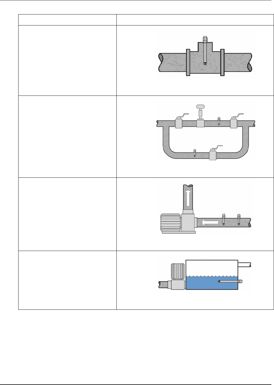
Probe mounting locations
The corrosion probe must be installed in a location that is most susceptible to corrosion. In most cases,
corrosion tends to occur where water is trapped or stagnant. However, it can also accelerate at the bend of
the pipe or where corrosion has occurred previously, but is accelerated by high flow or turbulence.
Location Picture
Incorrect probe location
The probe should not be mounted in a
pipe drop since the corrosive liquid
may not be in full contact with the
electrodes.
Correct probe location
The probe should be mounted in the
riser of a pipe near an elbow where
the velocity is the highest. In general,
probe should be mounted in pipes or
tanks at locations of highest liquid
velocity and constant immersion.
Correct Pipeline Position
Probe can be located at any point on
the pipeline but should always be
immersed in the corrosive material.
3. Process insertion
3.4. Corrosion models
R100 OneWireless XYR 6000 Transmitters Quick Start Guide 15
7/23/07
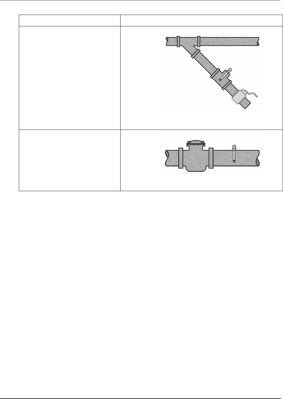
Location Picture
Located in Tee
Probe can be located at any point on
the pipeline but should always be
immersed in the corrosive material.
Located in Bypass Loop
Probe should be located downstream
of a control valve for best performance
and can also be located in the deadleg
portion of a by-pass.
Note that the probe located in the by-
pass leg should be mounted before
the valve for best performance. This
guarantees the electrodes will always
be immersed in the corrosive material.
Mounted with Different Electrodes
Installing with different electrode
materials on the suction side of the
pump will ensure monitoring of the
pump impeller and the pipe.
Installed in a Condensate Flash Tank
A condensate flash tank is also a good
application.
3. Process insertion
3.4. Corrosion models
16 OneWireless XYR 6000 Transmitters Quick Start Guide R100
7/23/07
Location Picture
Mounted in Y-Strainer
The probe is shown in the blow down
of a Y-strainer.
Mounted in Basket Strainer
The probe is shown in the discharge
side of the basket strainer.
The electrodes should be selected to reflect the same metal properties as the piping or other components
that might be susceptible to corrosion. For example, in applications where the pipe is made of stainless
steel and the water pump’s impeller is made of carbon steel, the impeller will corrode faster than the pipe.
In this case it is advisable to select the electrodes to be the same material as the pump’s impeller.
3. Process insertion
3.4. Corrosion models
R100 OneWireless XYR 6000 Transmitters Quick Start Guide 17
7/23/07
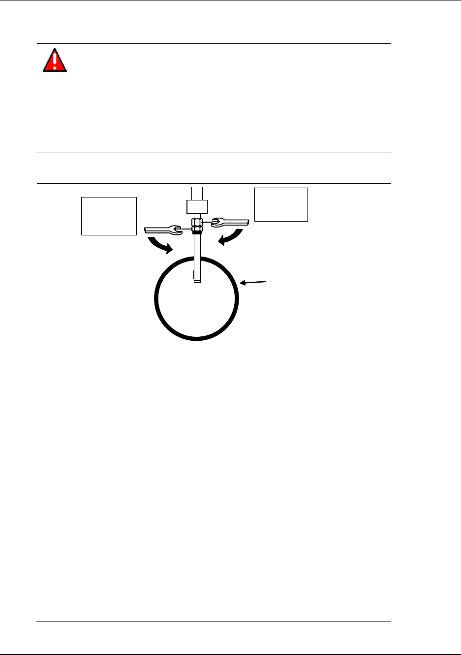
Probe installation
WARNING
If the pipe or vessel into which the probe is to be inserted is under pressure
and/or contains any hazardous substance, such as steam, caustic solutions,
acids, toxins or other substances specified by OSHA as physical or health
hazards, the pipe or vessel must first be depressurized and any hazardous
substance purged there from, and appropriate lockout/tagout procedures
observed in accordance with Section 1910.147 of the OSHA Regulations,
before the probe can be installed. Failure to follow these procedures may
result in serious injury or death.
Step Action
1 11/8”
Hex Flat
Pipe
11/16”
Hex Flat
11/8”
Hex Flat
Pipe
11/16”
Hex Flat
Some probes are supplied with an adjustable, compression NPT fitting (e.g.
Swagelok). With this fitting, follow this tightening sequence to ensure a tight
seal.
a) The Swagelok fitting should be held onto place with a plastic zip-tie
around the probe body. The zip-tie should be removed.
b) Determine the depth that the probe should extend into the pipe.
c) Tighten the larger upper nut until the tubing will not rotate freely by hand.
d) Make a mark on the nut. This mark will serve as a reference as the 6
o’clock position.
e) While holding fitting body steady, tighten the large upper nut 1 + 1⁄4 turns
to the 9 o’clock position.
f) This tightening sequence will crimp the internal ring onto the probe body
and should lock the fitting in place now.
g) Tighten the lower nut onto the pipe nipple or access point.
For fixed type probes (without the adjustable compression fitting) only the
1 1/16 hex nut needs to be tightened and the safety bracket is not required.
2 Ensure the flow rate of the process fluid does not exceed 20 feet per second
(fps). Stronger flow might damage probes with three finger electrodes and
interfere with the reading. If the flow rate exceeds the recommendation, a
different probe style may be required.
3. Process insertion
3.4. Corrosion models
18 OneWireless XYR 6000 Transmitters Quick Start Guide R100
7/23/07
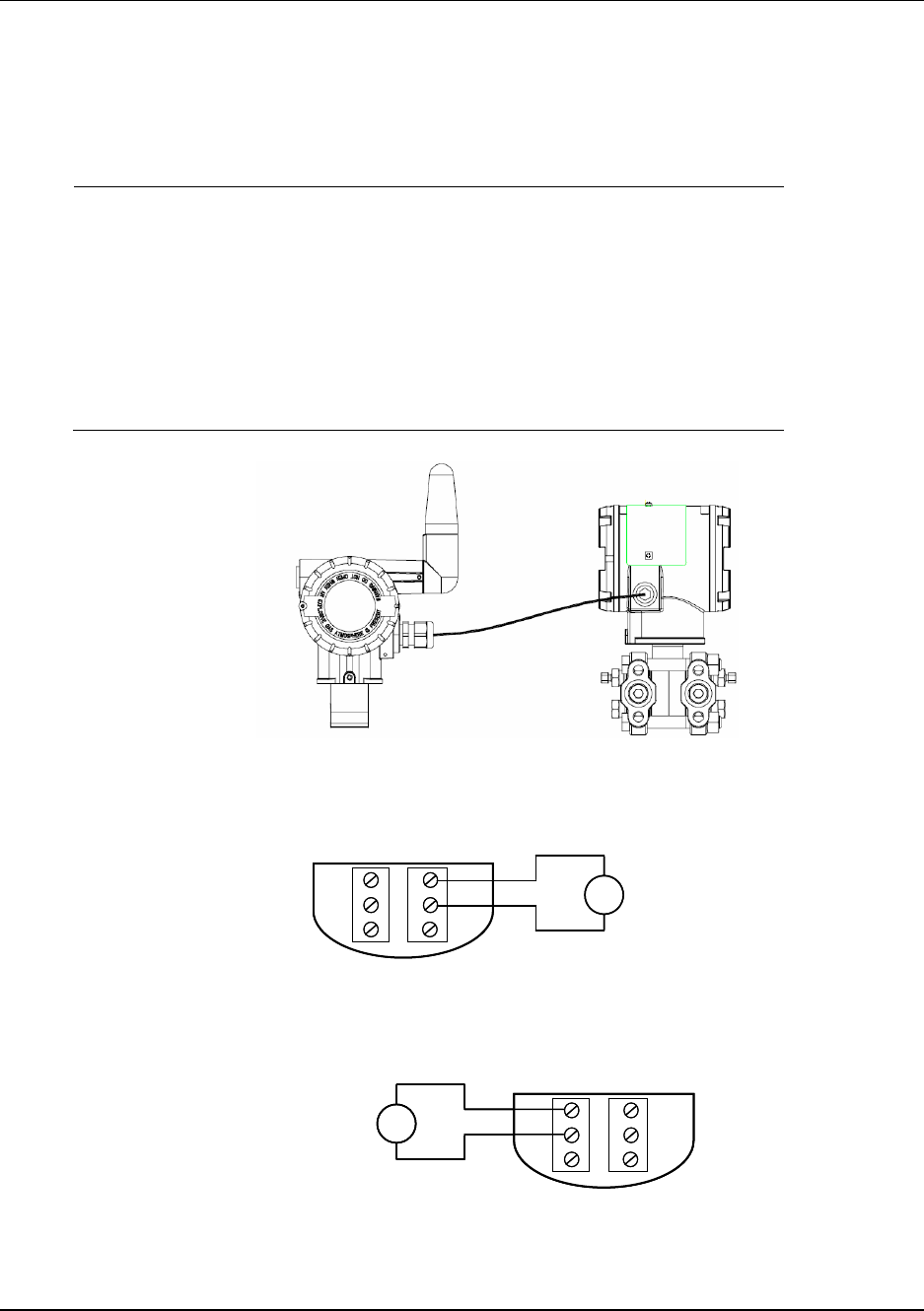
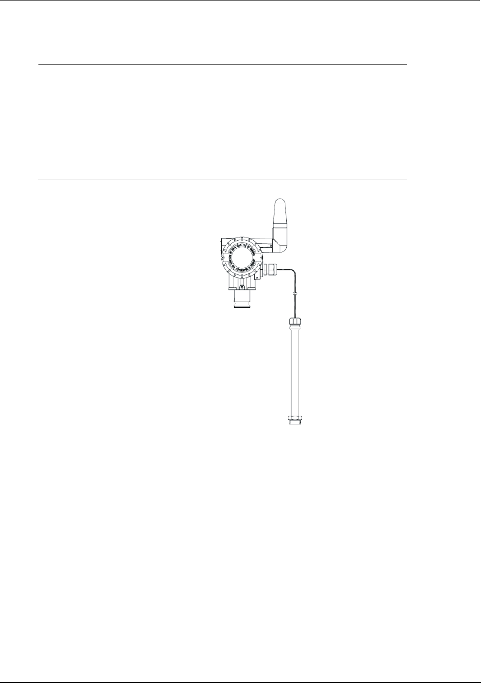
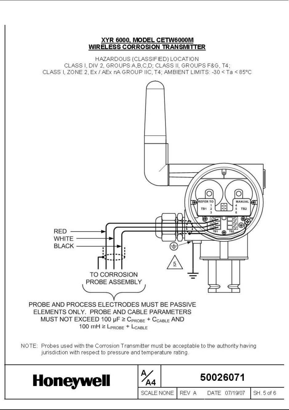
Connect wiring
Step Action
1 See Figure 10. Open the transmitter’s rear end cap (opposite end from
display).
2 Open the cable gland (on right side below antenna).
3 Feed probe wiring through the cable gland and connect to terminal block. See
Figure 10. See page 27 for terminal connections.
4 Plug battery connector into batteries.
5 Close rear end cap and cable gland.
Figure 10 Corrosion transmitter with remote probe
R100 OneWireless XYR 6000 Transmitters Quick Start Guide 19
7/23/07
4. Antenna adjustment and mounting
4.1 Requirements
Radio installation requirements
ATTENTION
Professional Installation is required to insure conformity with Federal Communications
Commission (FCC) in the USA, Industry Canada (IC) in Canada and the Radio and
Telecommunications Terminal Equipment Directive, 1999/5/EC (R&TTE), in the European
Union (EU).
Professional installation is required for the selection and installation of approved antennas and
setup of the maximum allowable radiated power from the XYR 6000 Wireless Transmitter as
configured for the particular installation site.
The antennae used for this transmitter must be installed to provide a separation distance of at
least 20 cm (8 inches) from all persons and must not be co-located or operating in conjunction
with any other antenna or transmitter.
For remote antenna, see antenna installation requirements to satisfy FCC RF exposure
requirements.
ATTENTION
Federal Communications Commission (FCC):
The XYR 6000 Wireless Transmitters comply with part 15 of the FCC rules. Operation is
subject to the following two conditions: (1) this device may not cause harmful interference, and
(2) this device must accept any interference received, including interference that may cause
undesired operation.
Industry Canada (IC):
The installer of this radio equipment must ensure that the antenna is located or pointed such
that it does not emit RF fields in excess of Health Canada limits for the general population;
consult Safety Code 6, obtainable from Health Canada’s web site www.hc-sc.gc.ca/rpb.
4.2 Integral antenna
WARNING
POTENTIAL ELECTROSTATIC CHARGING HAZARD
The integrally mounted antenna shroud is made of Teflon® and has a surface
resistance greater than 1Gohm per square. When the XYR 6000 transmitter
is installed in potentially hazardous locations care should be taken not to
electrostatically charge the surface of the antenna shroud by rubbing the
surface with a cloth, or cleaning the surface with a solvent. If electrostatically
charged, discharge of the antenna shroud to a person or a tool could possibly
ignite a surrounding hazardous atmosphere.
4. Antenna adjustment and mounting
4.2. Integral antenna
20 OneWireless XYR 6000 Transmitters Quick Start Guide R100
7/23/07
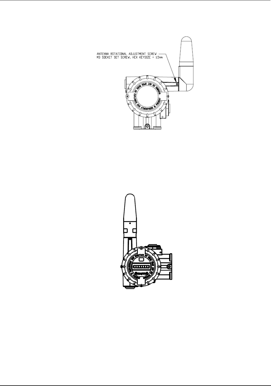
Elbow
Figure 11 Elbow antenna adjustment
If your model has the integral elbow anntena you can adjust it to improve operation. Typically, pointed
straight up gives best performance but your installation may vary. Loosen the 1.5mm set screw located
near the antenna base. Rotate antenna for best reception. Do not rotate antenna more than 180 degrees
either direction or you could damage internal wiring. Tighten set screw.
Straight
Figure 12 Integral straight antenna
4. Antenna adjustment and mounting
4.3. Remote antenna
R100 OneWireless XYR 6000 Transmitters Quick Start Guide 21
7/23/07
If your model has the integral straight anntena (Figure 12) you can adjust its position by rotating the
transmitter housing. (See page 6.) Typically, pointed straight up gives best performance but your
installation may vary.
4.3 Remote antenna
Outdoor installation warnings
WARNING
LIVES MAY BE AT RISK! Carefully observe these instructions and any special instructions
that are included with the equipment you are installing.
WARNING
Contacting power lines can be lethal.
Look over the site before beginning any installation, and anticipate possible hazards,
especially these:
Make sure no power lines are anywhere where possible contact can be made. Antennas,
masts, towers, guy wires or cables may lean or fall and contact these lines. People may be
injured or killed if they are touching or holding any part of equipment when it contacts electric
lines. Make sure there is NO possibility that equipment or personnel can come in contact
directly or indirectly with power lines.
Assume all overhead lines are power lines.
The horizontal distance from a tower, mast or antenna to the nearest power line should be at
least twice the total length of the mast/antenna combination. This will ensure that the mast will
not contact power if it falls either during installation or later.
WARNING
To avoid falling, use safe procedures when working at heights above ground.
Select equipment locations that will allow safe, simple equipment installation.
Don’t work alone. A friend or co-worker can save your life if an accident happens.
Use approved non-conducting ladders and other safety equipment. Make sure all equipment is
in good repair.
If a tower or mast begins falling, don’t attempt to catch it. Stand back and let it fall.
If anything such as a wire or mast does come in contact with a power line, DON’T TOUCH IT
OR ATTEMPT TO MOVE IT. Instead, save your life by calling the power company.
Don’t attempt to erect antennas or towers on windy days.
4. Antenna adjustment and mounting
4.3. Remote antenna
22 OneWireless XYR 6000 Transmitters Quick Start Guide R100
7/23/07
WARNING
MAKE SURE ALL TOWERS AND MASTS ARE SECURELY GROUNDED, AND
ELECTRICAL CABLES CONNECTED TO ANTENNAS HAVE LIGHTNING ARRESTORS.
This will help prevent fire damage or human injury in case of lightning, static build-up, or short
circuit within equipment connected to the antenna.
The base of the antenna mast or tower must be connected directly to the building protective
ground or to one or more approved grounding rods, using 1 OAWG ground wire and
corrosion-resistant connectors.
Refer to the National Electrical Code for grounding details.
Lightning arrestors for antenna feed coaxial cables are available from HyperLink
Technologies, Inc.
WARNING
If a person comes in contact with electrical power, and cannot move:
DON’T TOUCH THAT PERSON, OR YOU MAY BE ELECTROCUTED.
Use a non-conductive dry board, stick or rope to push or drag them so they no longer are in
contact with electrical power.
Once they are no longer contacting electrical power, administer CPR if you are certified, and
make sure that emergency medical aid has been requested.
4. Antenna adjustment and mounting
4.3. Remote antenna
R100 OneWireless XYR 6000 Transmitters Quick Start Guide 23
7/23/07
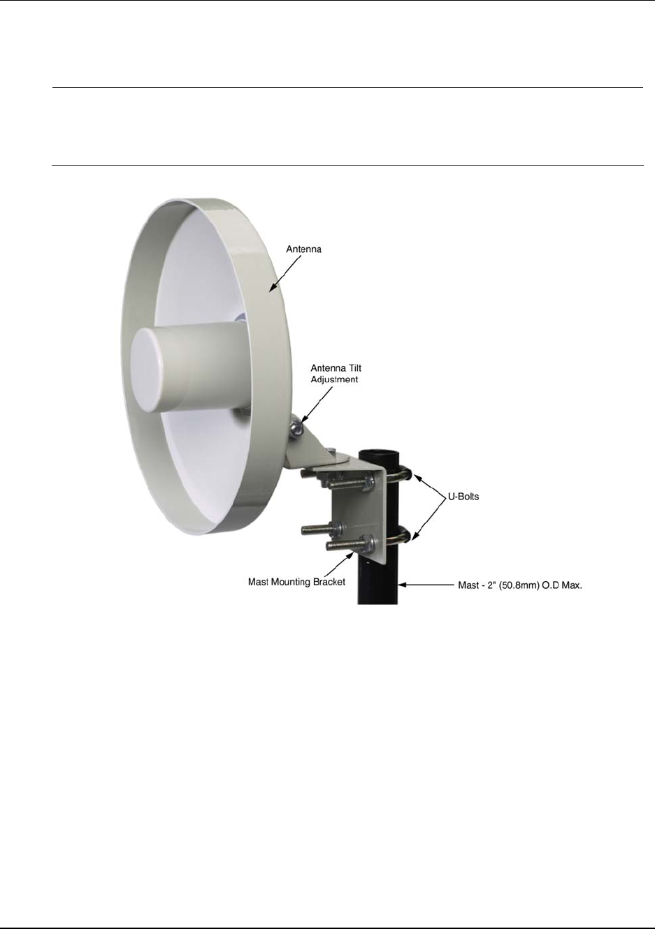
Directional mounting procedure
Step Action
1 Secure mast mounting bracket to mast as shown using 2 U-bolts and supplied hardware.
2 Attach antenna to mast mounting bracket as shown using supplied hardware.
3 Adjust antenna to desired tilt and lock into place using the antenna tilt adjustment nut.
Figure 13 Directional antenna mounting
4. Antenna adjustment and mounting
4.3. Remote antenna
24 OneWireless XYR 6000 Transmitters Quick Start Guide R100
7/23/07
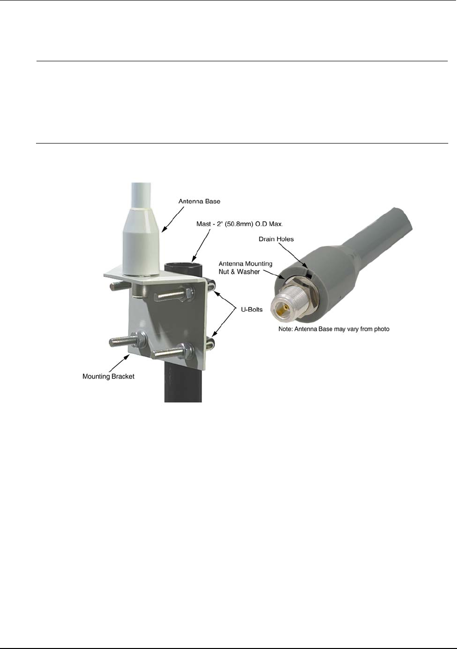
Omnidirectional mounting procedure
Step Action
1 Secure mast mounting bracket to mast as shown using 2 U-bolts and supplied hardware.
2 Remove antenna mounting bolt and washer from antenna base.
3 Insert antenna into mounting bracket and secure with washer and antenna mounting bolt. Do
not overtighten.
4 Any drain holes in the antenna base must be kept clear for proper operation.
Figure 14 Omnidirection antenna mounting
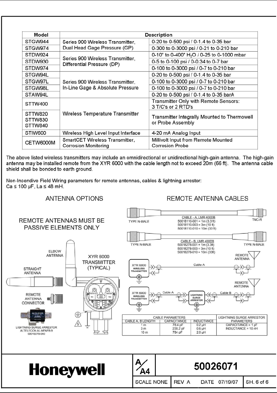
Connect antenna to transmitter
Using coaxial cable, connect the antenna base to the transmitter’s remote antenna connector (located at top
right as you face the transmitter display). A lightning arrestor may be required between the antenna and the
transmitter, using two cables up to 10m long each. Without lightning arrester, total cable length must not
exceed 10m (33 ft.). With lightning arrester total cable length must not exceed 20m (66 ft.). Antenna cable
shield shall be bonded to earth ground.
See page for cable types and connection information.
5. Start up
5.1. Connect batteries
R100 OneWireless XYR 6000 Transmitters Quick Start Guide 25
7/23/07
5. Start up
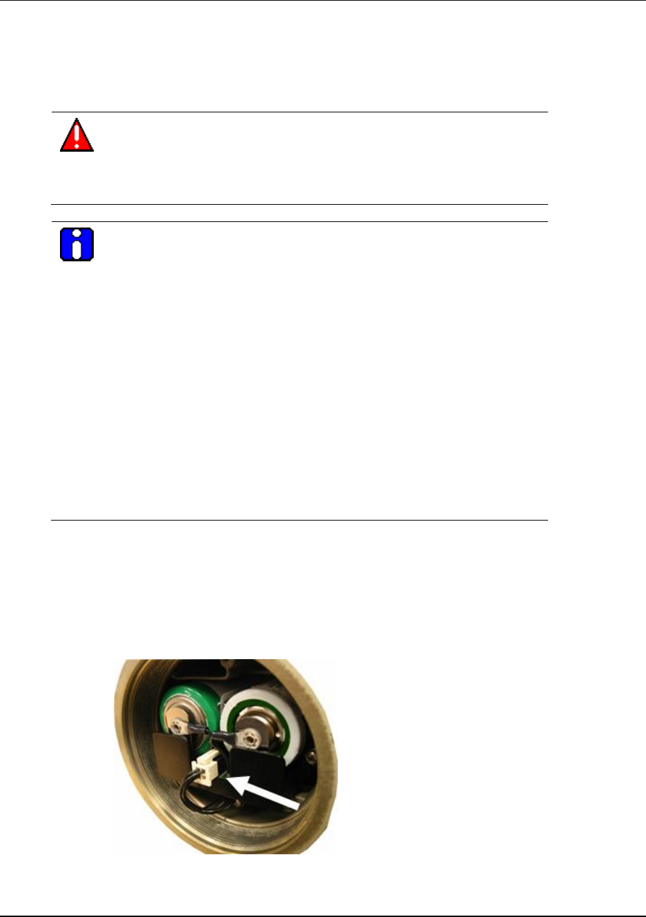
5.1 Connect batteries
WARNING
Risk of death or serious injury from explosion or fire.
Connection and disconnection of the batteries should be done only when the
area is non-hazardous.
ATTENTION
Both batteries must be the same model from the same manufacturer. Mixing
old and new batteries or different manufacturers is not permitted.
Use only the following 3.6V lithium thionyl chloride (Li-SOCl2) batteries (non-
rechargeable), size D. No other batteries are approved for use in XYR 6000
Wireless Transmitters.
• Xeno Energy XL-205F
• Eagle Picher PT-2300H
• Tadiran TL-5930/s
• Honeywell p/n 50026010-001 (Two 3.6V lithium thionyl chloride
batteries)
• Honeywell p/n 50026010-002 (Four 3.6V lithium thionyl chloride
batteries)
• Honeywell p/n 50026010-003 (Ten 3.6V lithium thionyl chloride batteries)
Step Action
1 Loosen the M3 locking set screw on the battery end-cap (opposite end from display). See item
1 in Figure 15. Unscrew and remove the end cap.
2 Attach connector to batteries as shown.
3 Screw the end cap back on and tighten the M3 locking screw.
5. Start up
5.1. Connect batteries
26 OneWireless XYR 6000 Transmitters Quick Start Guide R100
7/23/07
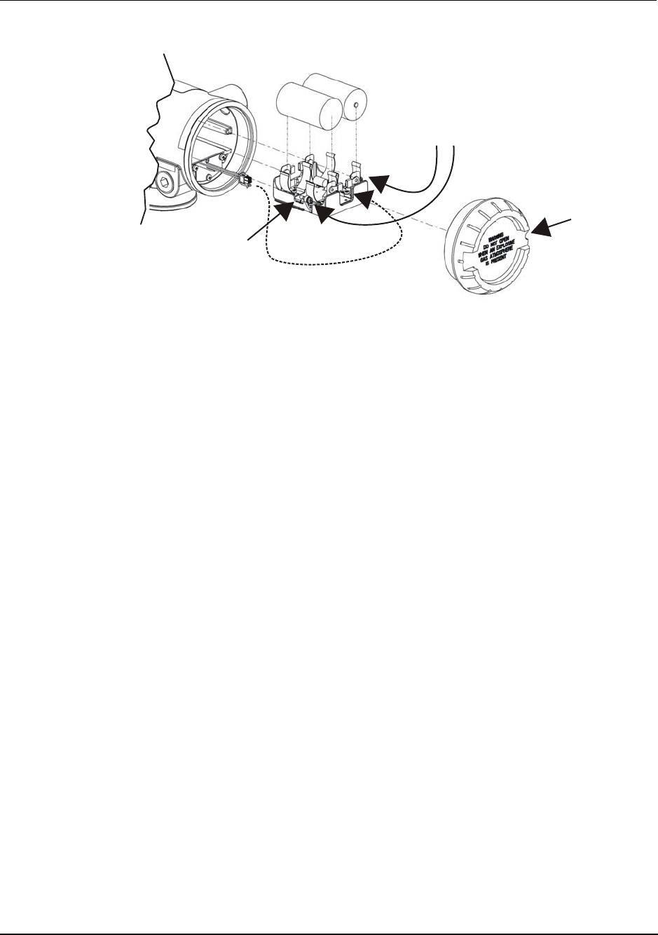
1
2
+
-
+
-3
4
Figure 15 Battery assembly
Display sequence
After power up, the transmitter does a brief self-test of the LCD display. Then it proceeds to Power-On
Message, which is the model name of the transmitter. The name is displayed for 2 seconds after which the
transmitter displays the process variables and associated status.
Authentication
Before the transmitter can be configured it must be unlocked with a security key so it can join the network.
Use the Authentication Device Pocket PC software to receive security keys from the Key Server manager,
then aim the Pocket PC at the transmitter and transmit a key.

R100 OneWireless XYR 6000 Transmitters Quick Start Guide 27
7/23/07
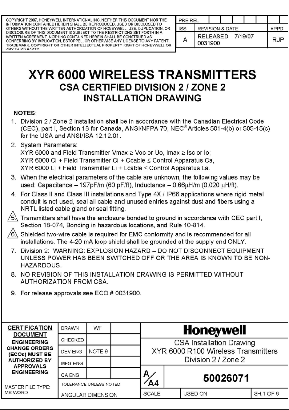
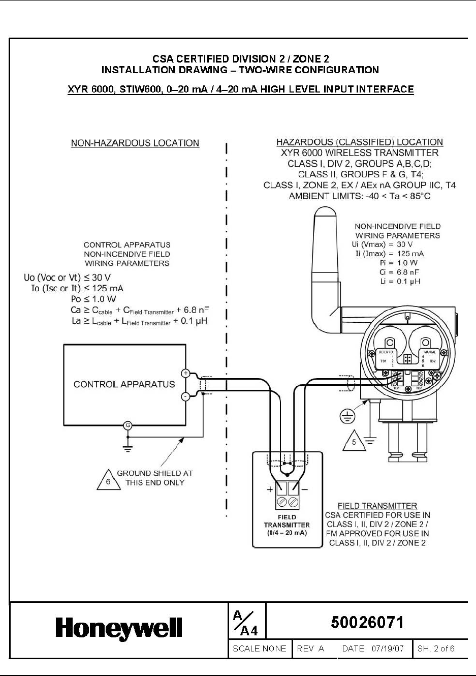
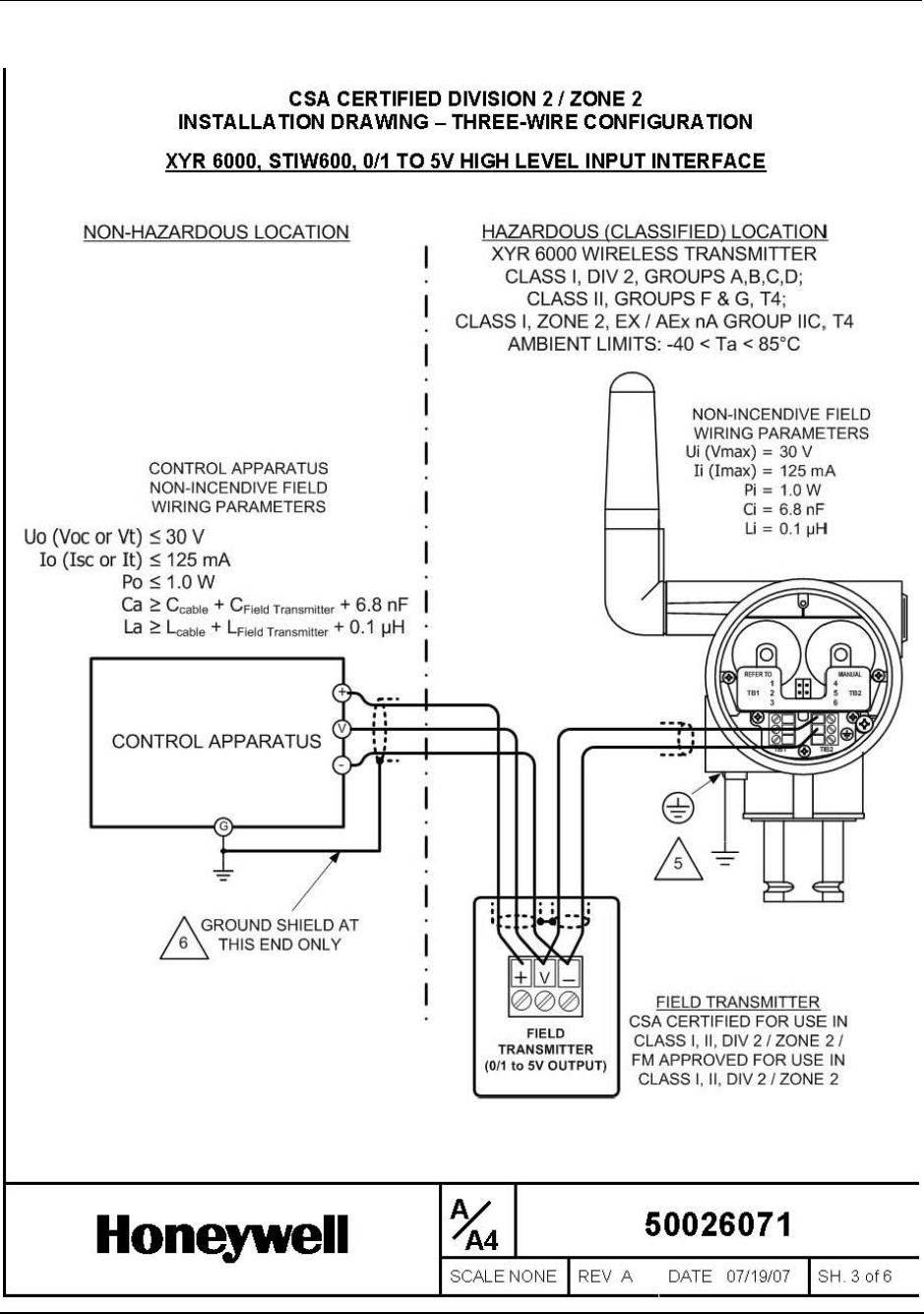
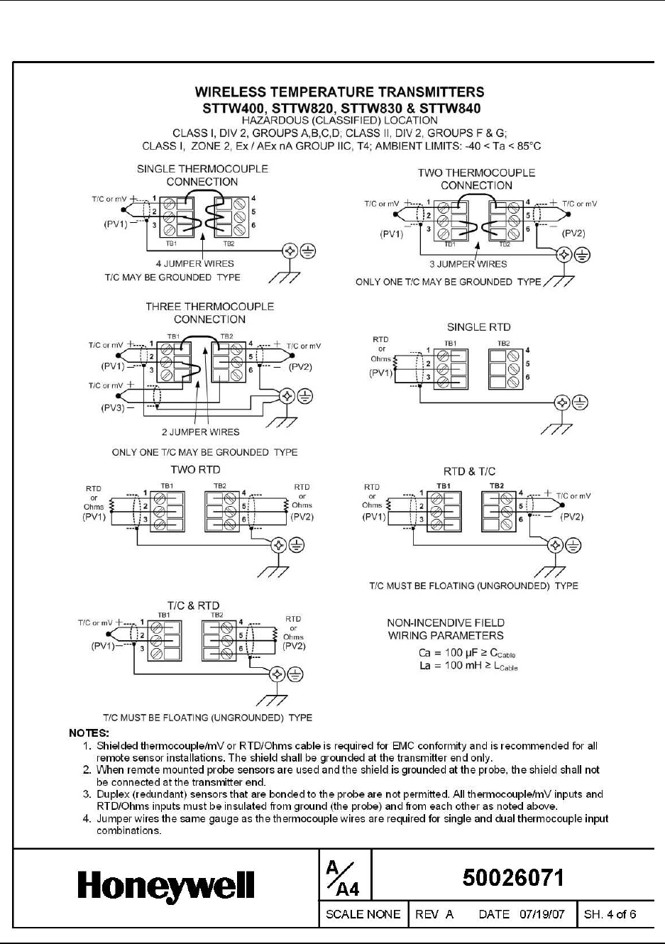
6. CSA Certified DIVISION 2 / ZONE 2 Installation Drawings
Use the following drawings and accompanying notes and text for hazardous locations. For non-hazardous
locations you can use the same drawings without the accompanying notes and text.
6. CSA Certified DIVISION 2 / ZONE 2 Installation Drawings
28 OneWireless XYR 6000 Transmitters Quick Start Guide R100
7/23/07
6. CSA Certified DIVISION 2 / ZONE 2 Installation Drawings
R100 OneWireless XYR 6000 Transmitters Quick Start Guide 29
7/23/07
6. CSA Certified DIVISION 2 / ZONE 2 Installation Drawings
30 OneWireless XYR 6000 Transmitters Quick Start Guide R100
7/23/07
6. CSA Certified DIVISION 2 / ZONE 2 Installation Drawings
R100 OneWireless XYR 6000 Transmitters Quick Start Guide 31
7/23/07
6. CSA Certified DIVISION 2 / ZONE 2 Installation Drawings
32 OneWireless XYR 6000 Transmitters Quick Start Guide R100
7/23/07
6. CSA Certified DIVISION 2 / ZONE 2 Installation Drawings
R100 OneWireless XYR 6000 Transmitters Quick Start Guide 33
7/23/07

6. CSA Certified DIVISION 2 / ZONE 2 Installation Drawings
34 OneWireless XYR 6000 Transmitters Quick Start Guide R100
7/23/07

Honeywell International
Process Solutions
2500 West Union Hills
Phoenix, AZ 85027