Honeywell 6510GP Mobile Computer User Manual
Honeywell International Inc Mobile Computer
UserManual.wiki
>
Honeywell
>
6510GP User Manual
User Manual
Navigation menu
Upload a User Manual
Namespaces
Wiki Guide
HTML
PDF
Info
Views
User Manual
Discussion / Help
Navigation

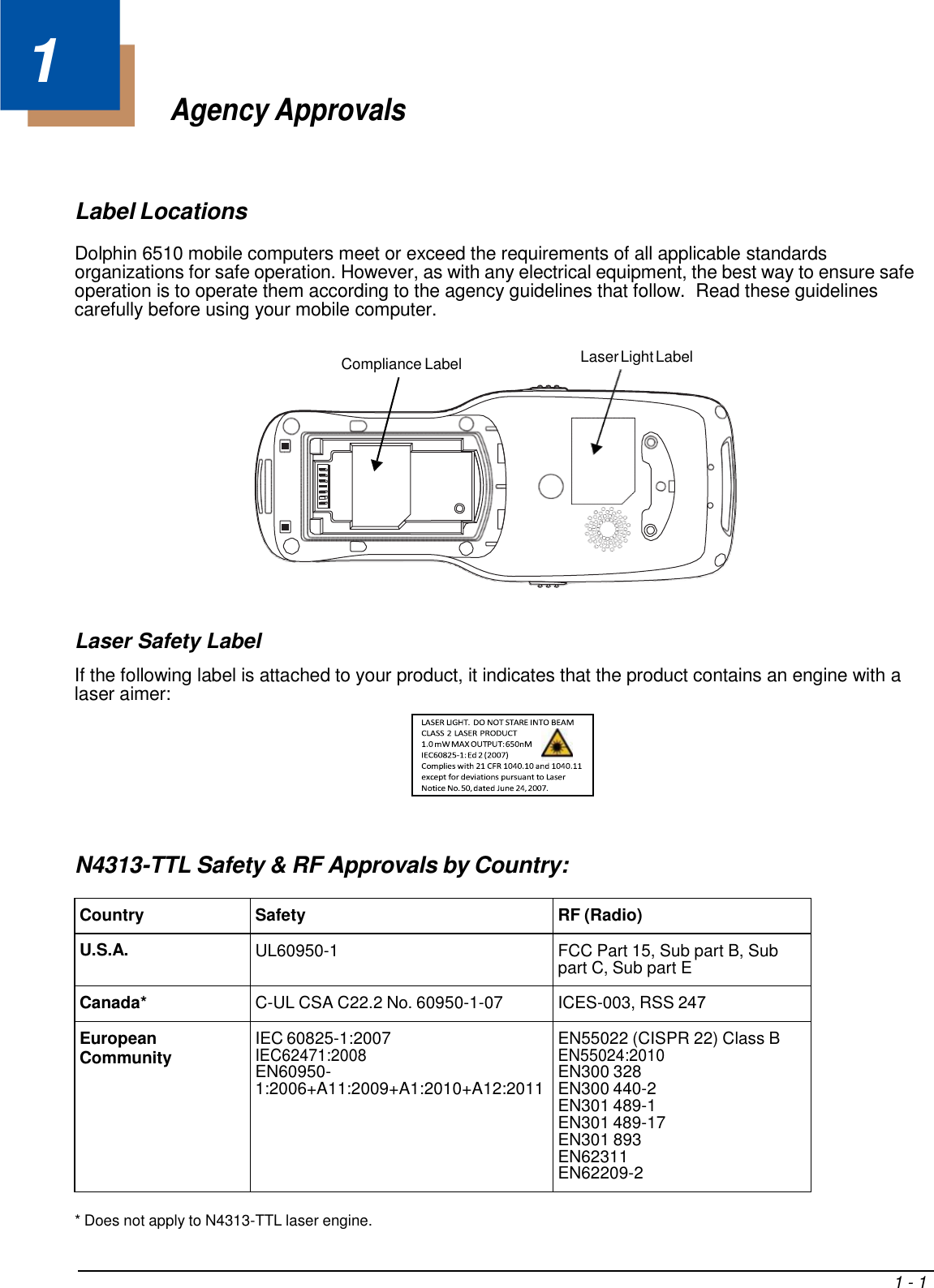

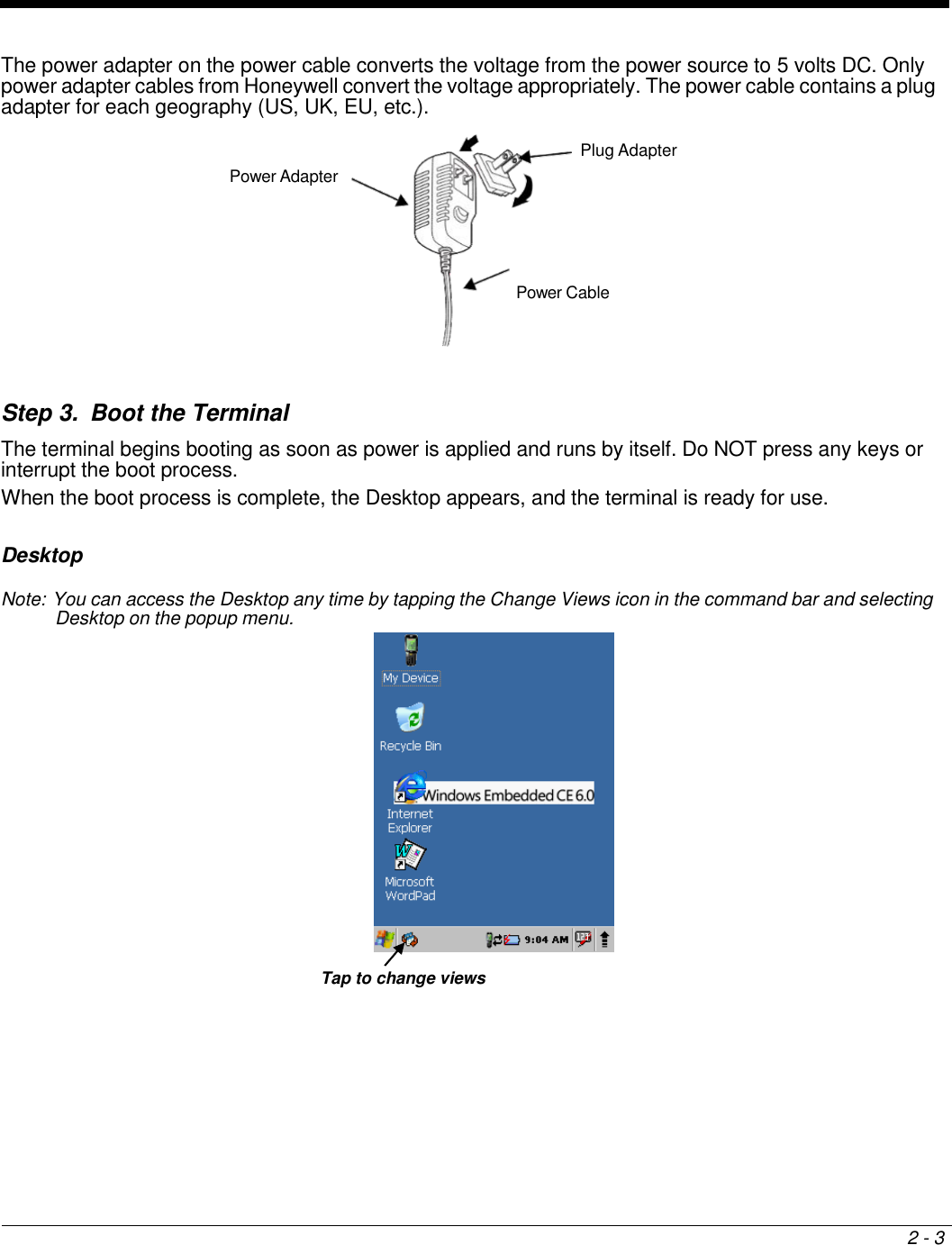
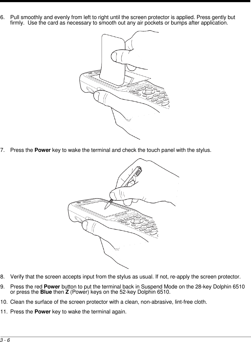
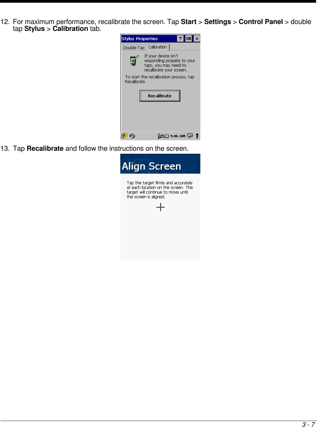
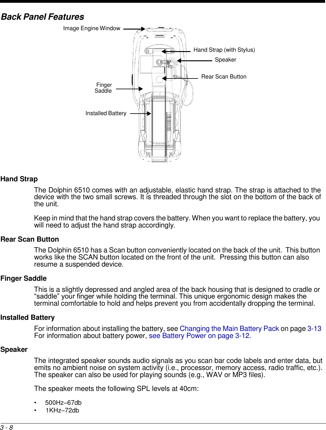
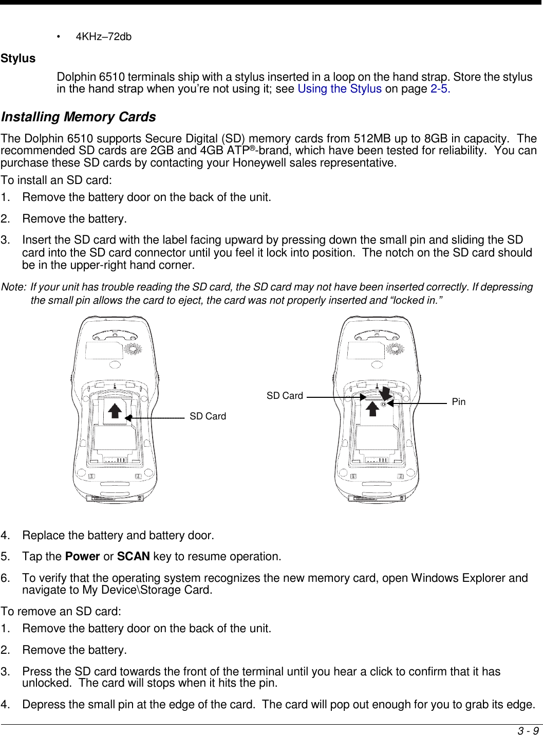
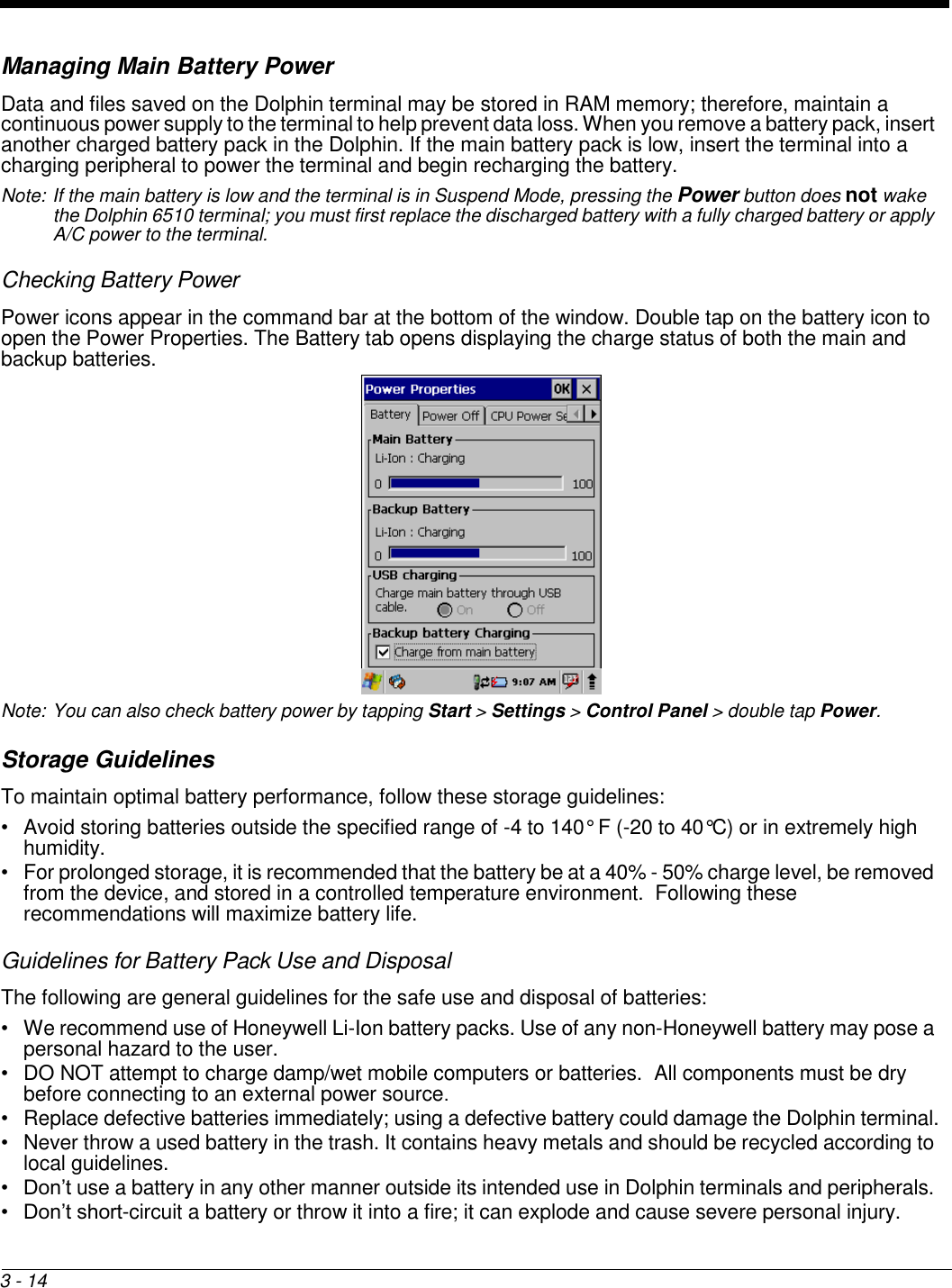
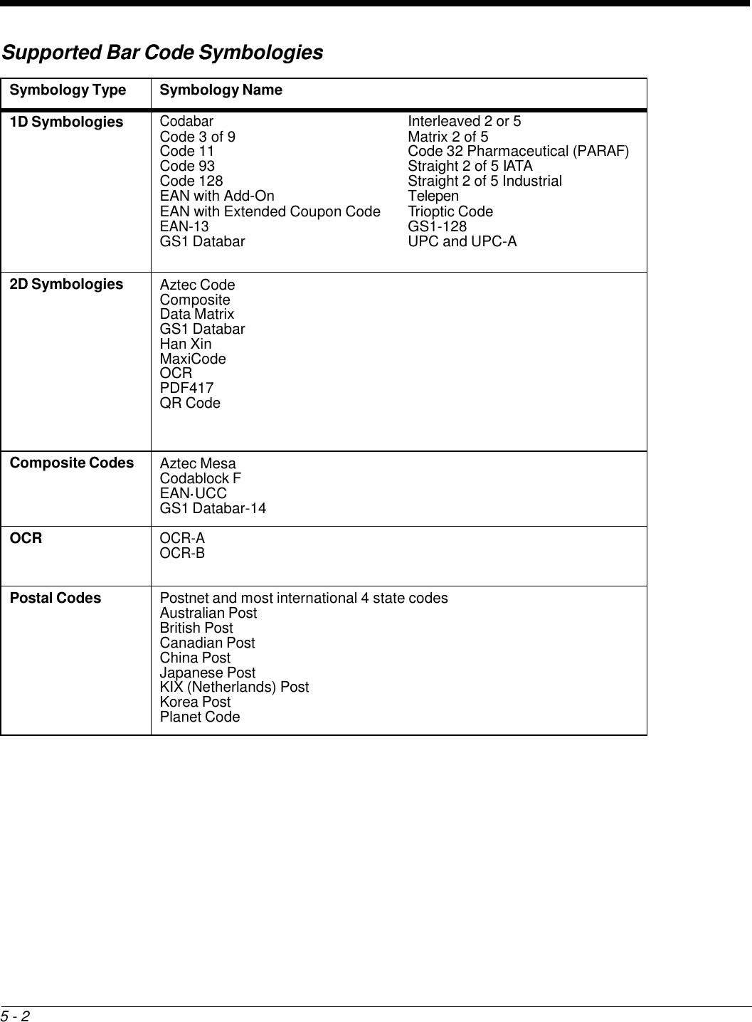
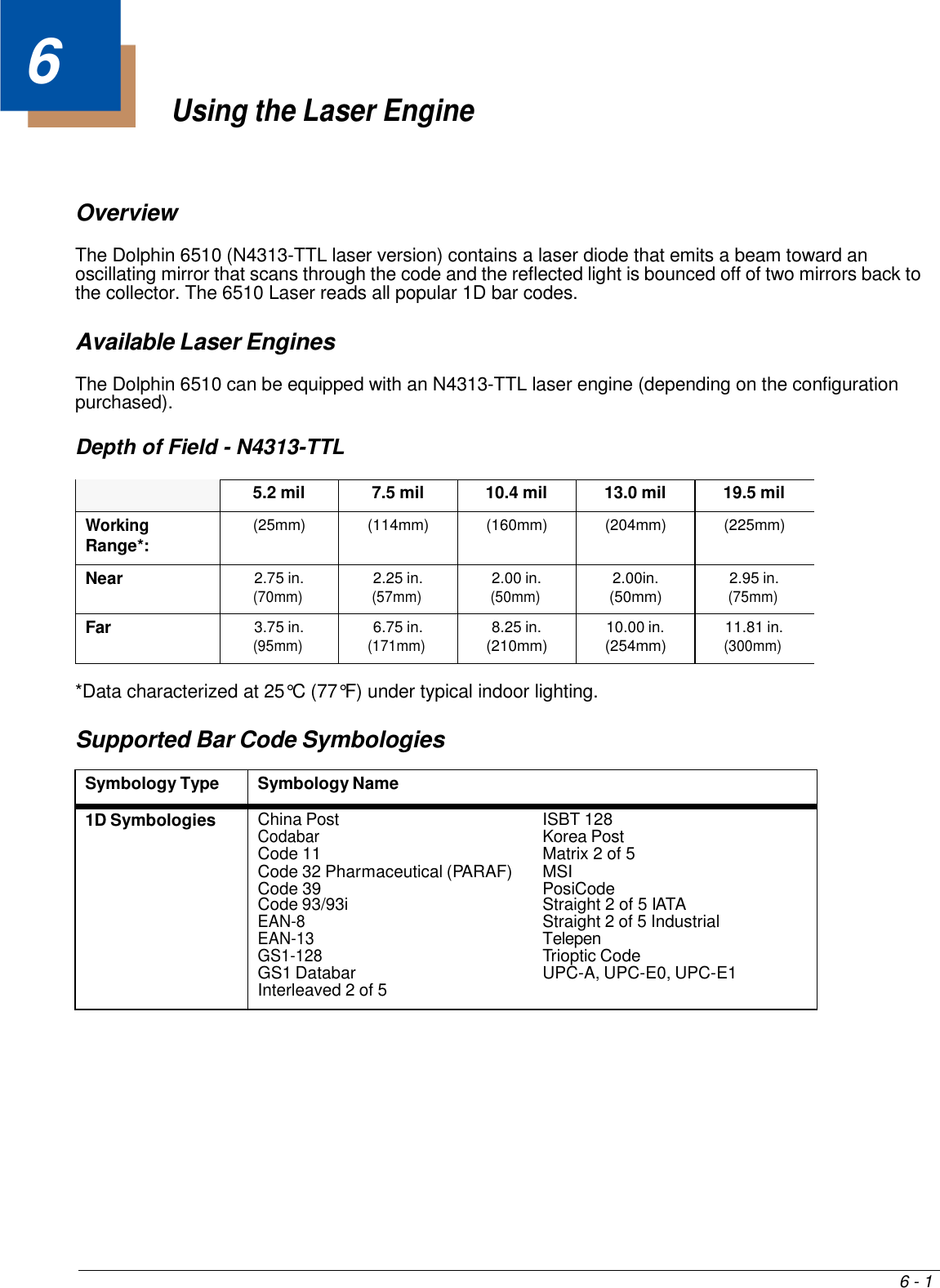
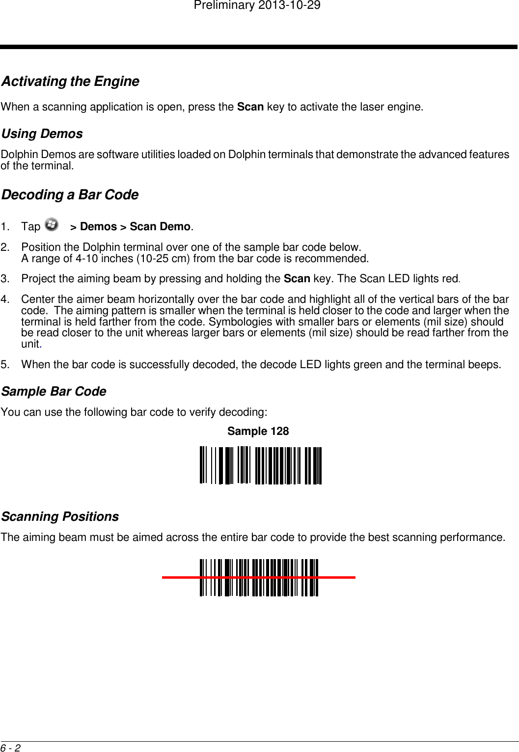
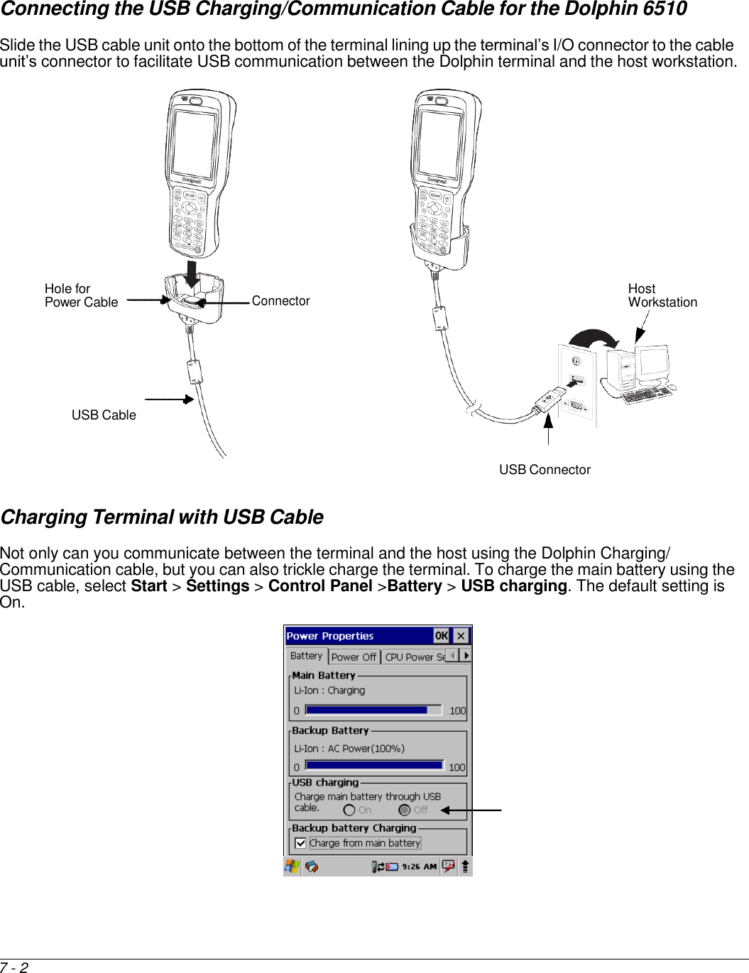
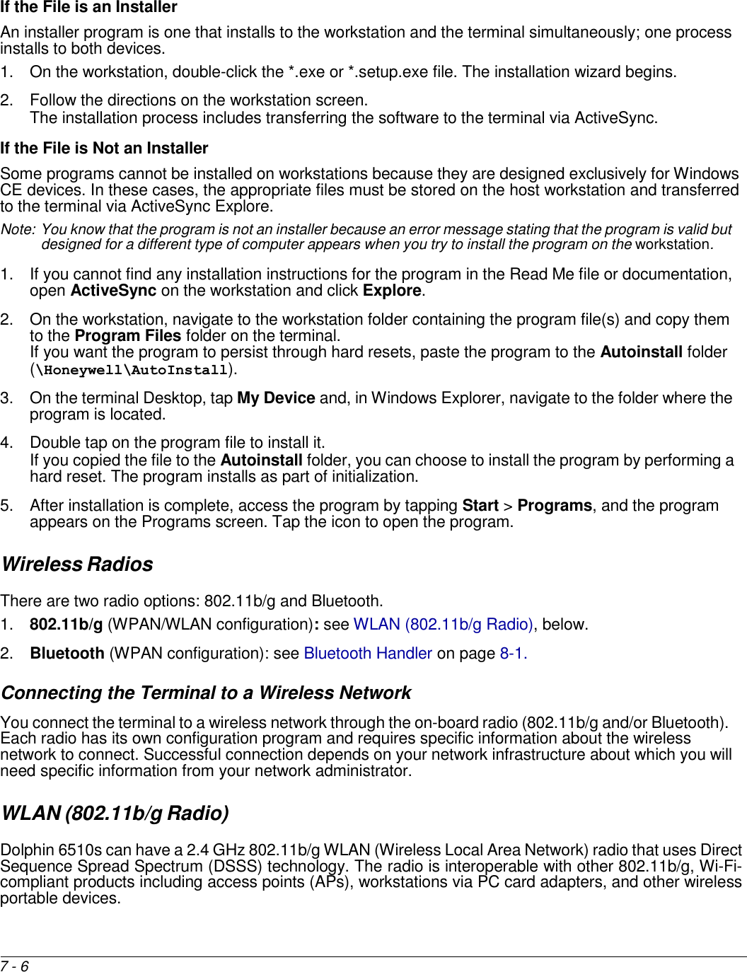
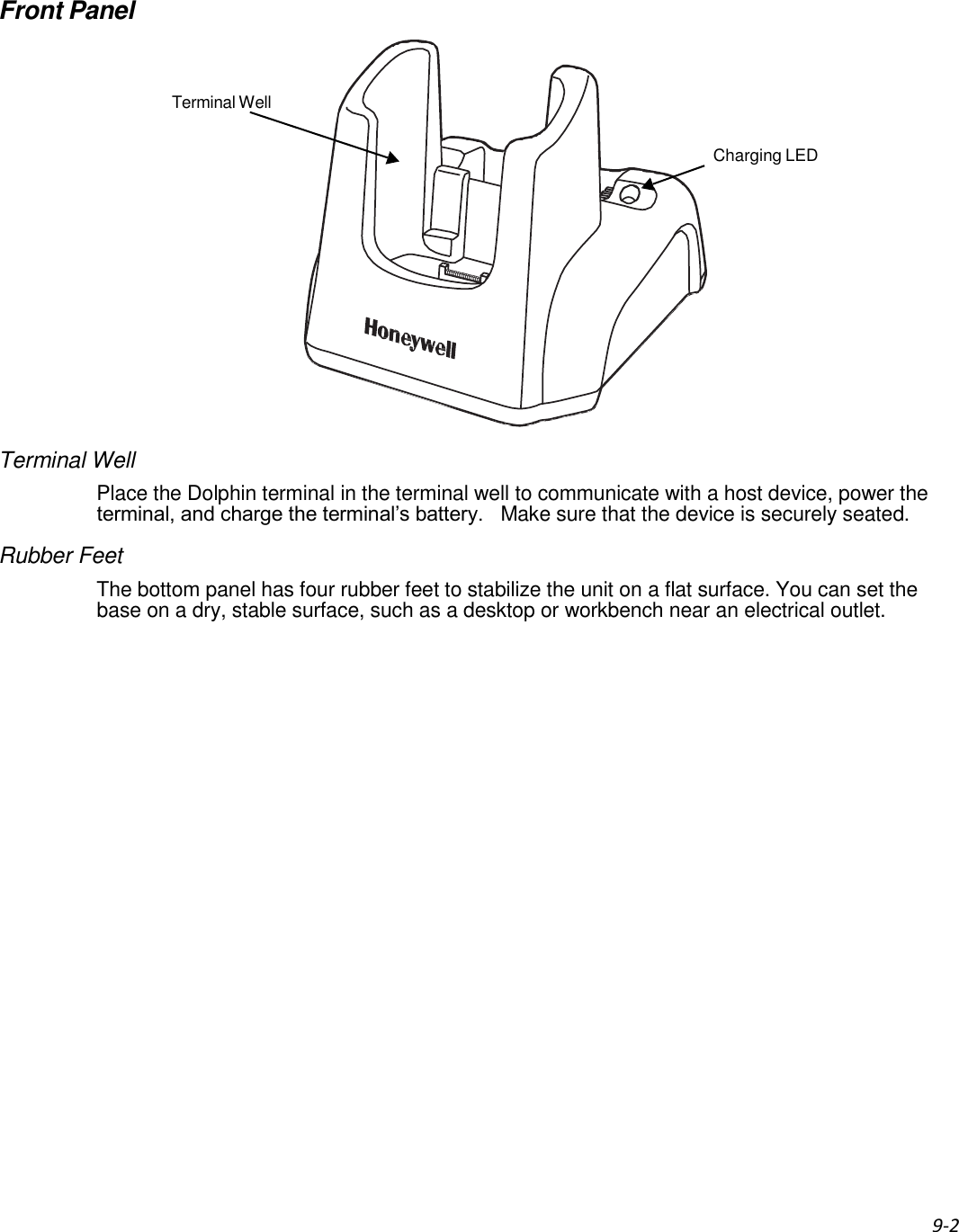
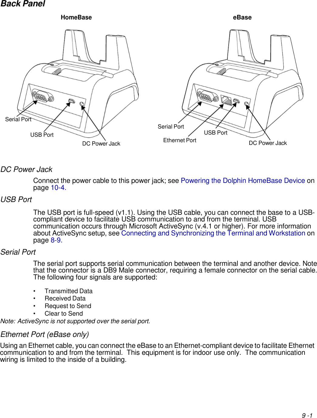
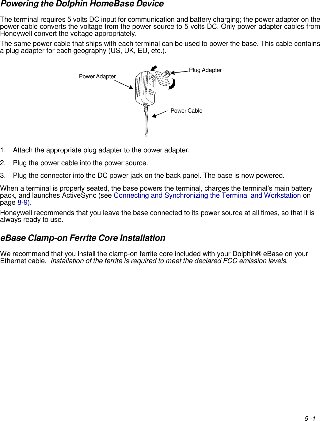
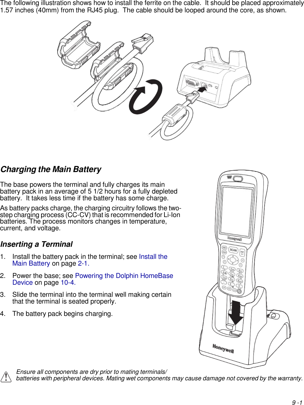
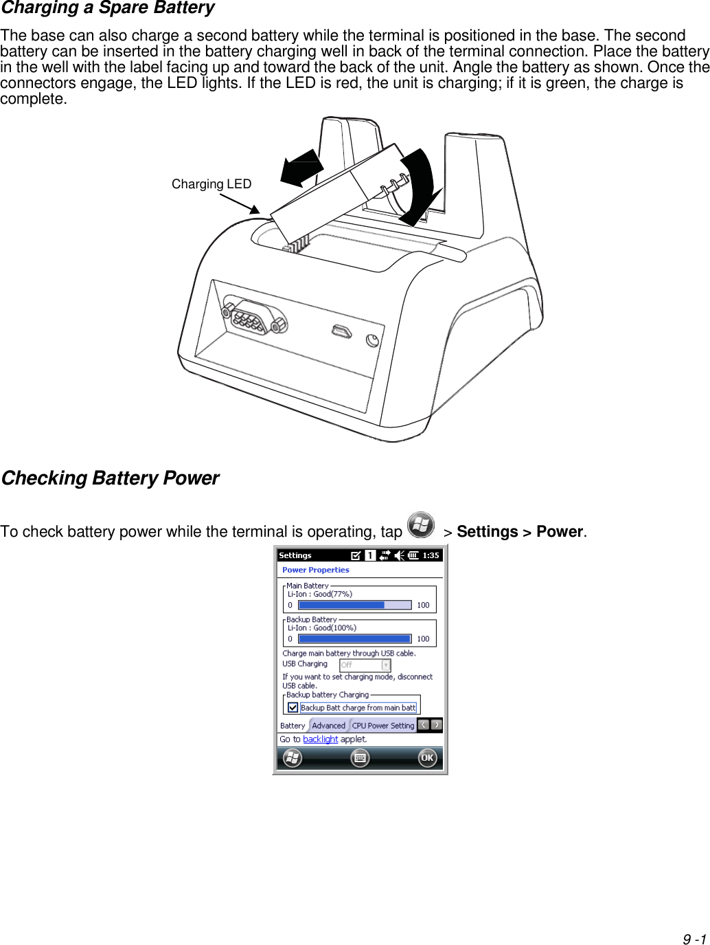
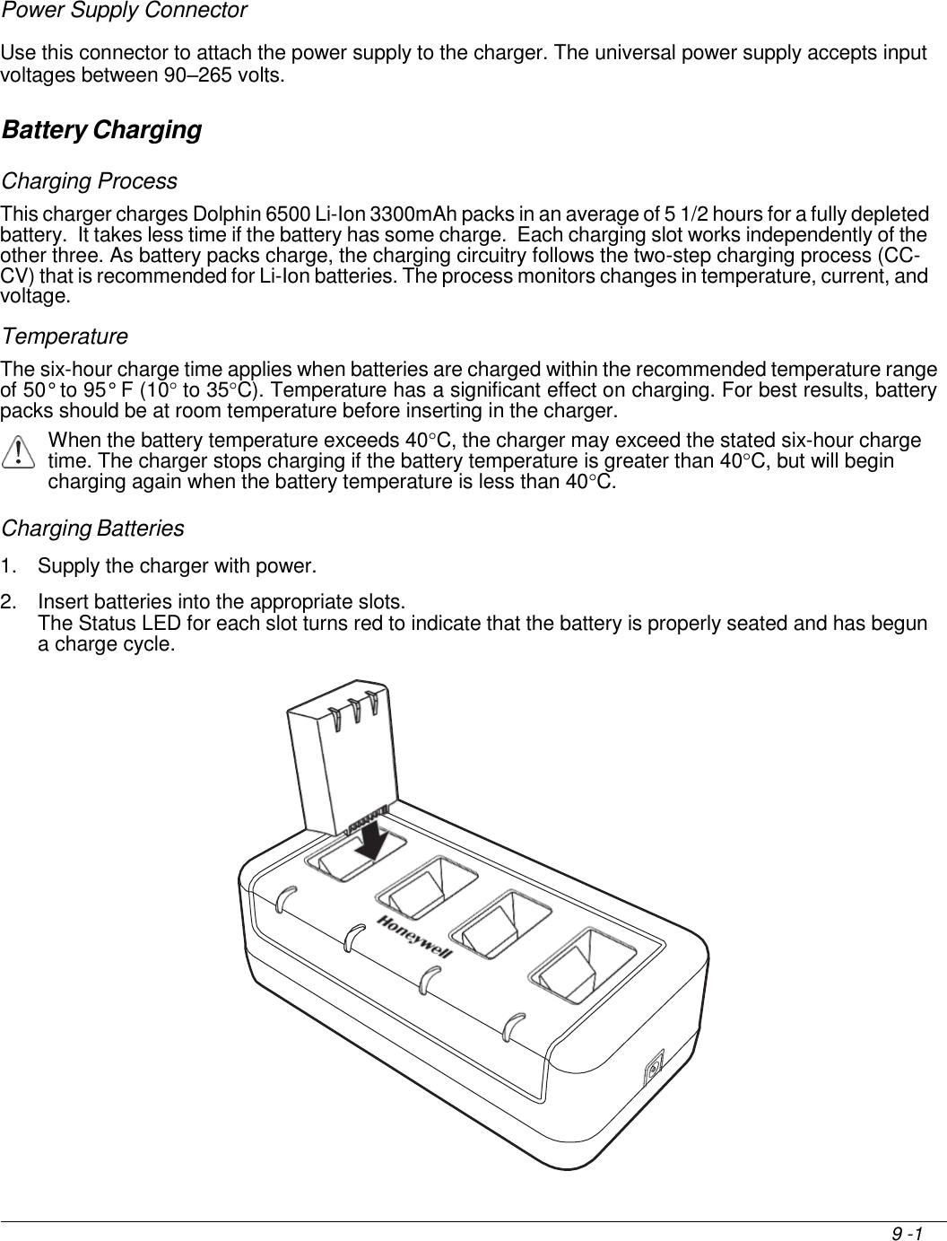
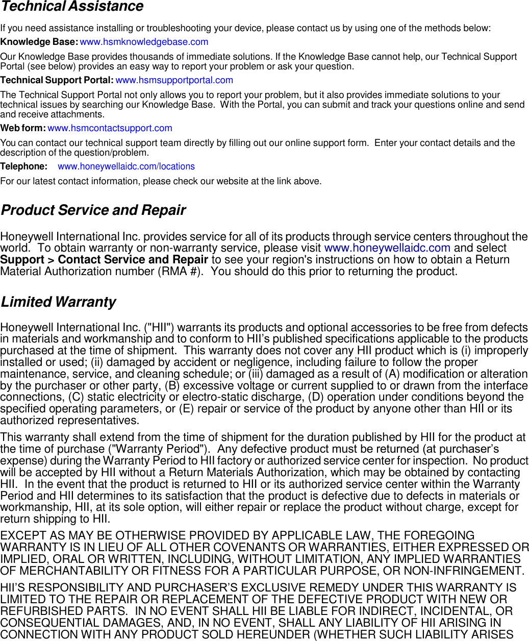
![3. Then, using the appropriate nuts and bolts, secure the DIN Rail to a stable, flat horizontal surface. DIN Rail (7.5 X 35 mm) Wall Mounting The optional wall mount bracket enables secure mounting of the base on a vertical surface. The wall mount bracket can be used in conjunction with the DIN rail but does not require the DIN Rail for use. Hardware (Provided) • M3 x 9 mm self-tapping screws, #2 Phillips, Qty. 4 • 3/8 in. x 4 in. round head toggle bolt, 2-5/8 in. usable length, Qty. 4 • 3/8 in. x 2 1/2 in. length Hex Head Lag Screw, Qty. 4 Tools Required • Drill • 7/8 in. Drill Bit (for hollow wall installations) or 1/4 in. Drill Bit (for wood stud installation) • Phillips Screw Driver Hollow Wall Installation 1. Drill four pilot holes in the wall using a 7/8 in. drill bit. 13.78 in. [35 cm] 6.5 in. [16.5 cm] Wall Mount Holes Wall Mount Bracket](https://usermanual.wiki/Honeywell/6510GP/User-Guide-2953499-Page-77.png)