Honeywell 6510GP Mobile Computer User Manual
Honeywell International Inc Mobile Computer
User Manual

Dolphin
™
6510 Mobile Computer
with Windows
®
CE 6.0
User’s Guide

Disclaimer
Honeywell International Inc. (“HII”) reserves the right to make changes in specifications and other infor-
mation contained in this document without prior notice, and the reader should in all cases consult HII to
determine whether any such changes have been made. The information in this publication does not rep-
resent a commitment on the part of HII.
HII shall not be liable for technical or editorial errors or omissions contained herein; nor for incidental or
consequential damages resulting from the furnishing, performance, or use of this material.
This document contains proprietary information that is protected by copyright. All rights are reserved.
No part of this document may be photocopied, reproduced, or translated into another language without
the prior written consent of HII.
Web Address: www.honeywellaidc.com
Trademarks
Dolphin is a trademark or registered trademarks of Hand Held Products, Inc. or Honeywell International
Inc.
Microsoft, Windows, Windows Mobile, Windows Embedded Handheld, Windows CE, Windows NT,
Windows 2000, Windows ME, Windows XP, ActiveSync, Outlook, and the Windows logo are trademarks
or registered trademarks of Microsoft Corporation.
Other product names mentioned in this manual may be trademarks or registered trademarks of their
respective companies and are the property of their respective owners.
Other Trademarks
The Bluetooth trademarks are owned by Bluetooth SIG, Inc., U.S.A. and licensed to Honeywell
International Inc.
Patents
For patent information, please refer to www.honeywellaidc.com/patents.
©2013 Honeywell International Inc. All rights reserved.

Table of Contents
Chapter 1 - Agency Approvals
Label Locations ................................................................................................................. 1-1
N4313-TTL Safety & RF Approvals by Country: ................................................................. 1-1
R&TTE Compliance Statement – 802.11a/b/g/n/ and or Bluetooth……………………. ....... 1-2
Dolphin RF Terminal—802.11a/b/g/n and/or Bluetooth ...................................................... 1-2
Chapter 2 - Getting Started
Out of the Box ................................................................................................................... 2-1
Initial Setup for Dolphin 6510 Terminals ............................................................................. 2-1
LED Indicators ............................................................................................................. 2-2
Home Screen .................................................................................................................... 2-4
Title Bar ............................................................................................................................. 2-4
Horizontal Scroll ................................................................................................................ 2-5
Horizontal Scroll ................................................................................................................ 2-6
Tile Bar .............................................................................................................................. 2-6
Pop-Up Menus .................................................................................................................. 2-6
Selecting Programs ........................................................................................................... 2-6
File Explorer ...................................................................................................................... 2-7
File Provisioning on the Dolphin 6510 ................................................................................ 2-8
Search ............................................................................................................................... 2-8
Turning Power On/Off ........................................................................................................ 2-9
Suspend Mode ............................................................................................................ 2-9
Resetting the Terminal ....................................................................................................... 2-9
Chapter 3 - Hardware Overview
Standard Terminal Configurations...................................................................................... 3-1
Dolphin Peripherals/Accessories for the Dolphin 6510 ....................................................... 3-1
USB Communication Cable for the Dolphin 6510 ............................................................... 3-2
Front Panel Features ......................................................................................................... 3-2
Using the Touch Panel ...................................................................................................... 3-3
Installing a Screen Protector ........................................................................................ 3-4
Back Panel Features ......................................................................................................... 3-4
Left Side Panel Features ................................................................................................... 3-5
Right Side Panel Features ................................................................................................. 3-6
Top Panel Features ........................................................................................................... 3-6
Bottom Panel Features ...................................................................................................... 3-7
Battery Power .................................................................................................................... 3-7
Battery Pack ................................................................................................................ 3-8
Managing Battery Power .............................................................................................. 3-9
Storage Guidelines ...................................................................................................... 3-9
Hardware Maintenance .................................................................................................... 3-10
Installing Memory Cards ............................................................................................ 3-10
Dolphin 6510 Technical Specifications ............................................................................. 3-12
iii

Chapter 4 - Using the Keypad
Overview ............................................................................................................................4-1
Navigation Keys .................................................................................................................4-1
Basic Keys .........................................................................................................................4-1
Alpha/Numeric Modes ........................................................................................................4-2
Alpha Indicators on the Number Keys ...........................................................................4-2
Function Key Combinations ................................................................................................4-2
CTRL Key Combinations ....................................................................................................4-3
Program Buttons ................................................................................................................4-3
Chapter 5 - Using the Image Engine
Overview ............................................................................................................................5-1
Available Image Engines ....................................................................................................5-1
Depth of Field ...............................................................................................................5-1
Supported Bar Code Symbologies .....................................................................................5-2
Activating the Engine .........................................................................................................5-3
Capturing Images (56XX Engine only) ................................................................................5-3
Chapter 6 - Using the Laser Engine
Overview ............................................................................................................................6-1
Available Laser Engines .....................................................................................................6-1
Depth of Field - N4313-TTL ..........................................................................................6-1
Supported Bar Code Symbologies .....................................................................................6-1
Activating the Engine .........................................................................................................6-2
Decoding a Bar Code .........................................................................................................6-2
Chapter 7 - System Settings
Overview ............................................................................................................................7-1
Clock & Alarms ..................................................................................................................7-2
Personal Menu ...................................................................................................................7-3
Buttons. ........................................................................................................................7-3
Program Buttons ..........................................................................................................7-5
System Menu .....................................................................................................................7-8
About ...........................................................................................................................7-9
Backlight ......................................................................................................................7-9
Certificates ................................................................................................................. 7-10
Encryption .................................................................................................................. 7-11
HSM SystemInfo ........................................................................................................ 7-11
Error Reporting ........................................................................................................... 7-12
Managed Programs .................................................................................................... 7-12
Memory ...................................................................................................................... 7-12
Power. ........................................................................................................................ 7-14
Regional Settings. ...................................................................................................... 7-16
Remove Programs ..................................................................................................... 7-16
Screen ............................................................................................................................. 7-18
SIP Configuration .............................................................................................................7-19
iv

Task Manager .................................................................................................................. 7-20
Chapter 8 - Communication
Connecting the Dolphin 6510-USB Communication Cable ..................................................8-1
Charging Terminal with USB Cable ....................................................................................8-1
Connections Menu ............................................................................................................ 8-3
Receiving Data ...................................................................................................................8-3
Connections Manager ........................................................................................................8-4
To Access the Connections Manager ...........................................................................8-4
Tasks ...........................................................................................................................8-5
Advanced .....................................................................................................................8-6
Dolphin Wireless Manager .................................................................................................8-7
Dolphin Wireless Manager Window ..............................................................................8-7
Enabling the Radios. ....................................................................................................8-8
Accessing Radio Configuration Utilities .........................................................................8-8
Network Cards ...................................................................................................................8-9
Connecting and Synchronizing the Terminal and Workstation ............................................8-9
Installing Additional Software ........................................................................................... 8-12
Adding Programs Using ActiveSync or Windows Mobile Device Center ...................... 8-12
Connecting the Terminal to a Wireless Network ......................................................... 8-13
Adding Programs Using the Internet ........................................................................... 8-13
Software Upgrades .......................................................................................................... 8-14
Chapter 9 - Working with the Bluetooth Radio
Enabling the Bluetooth Radio .............................................................................................9-1
Pairing and Trusted Devices ..............................................................................................9-2
Connecting to Other Bluetooth Devices ..............................................................................9-2
Transferring Files ...............................................................................................................9-4
Making the Terminal Discoverable .....................................................................................9-6
Chapter 10 - Dolphin HomeBase (Model 6500-HB)/eBase
(Model 6500-EHB) Device
Overview ..........................................................................................................................10-1
Front Panel ......................................................................................................................10-2
Back Panel ....................................................................................................................... 10-3
Powering the Dolphin HomeBase Device ......................................................................... 10-4
eBase Clamp-on Ferrite Core Installation ......................................................................... 10-4
Charging the Battery ........................................................................................................ 10-5
Charging a Spare Battery ........................................................................................... 10-6
Checking Battery Power ................................................................................................... 10-6
Technical Specifications ................................................................................................... 10-7
Chapter 11 - Dolphin 6500 Net Base Device (Model 6500-NB)
Overview ..........................................................................................................................11-1
v

Parts and Functions ......................................................................................................... 11-2
Front Panel ................................................................................................................ 11-2
Back Panel ................................................................................................................. 11-3
Bottom Panel .............................................................................................................. 11-4
Power ..............................................................................................................................11-4
Connecting Power to the Net Base ............................................................................. 11-4
Charging the Battery ........................................................................................................ 11-5
To Power a Terminal and Charge its Battery .............................................................. 11-5
Communication ................................................................................................................11-5
Software Requirements .............................................................................................. 11-5
Connecting the Dolphin Terminal to the Net Base ............................................................ 11-5
Mounting the Net Base ..................................................................................................... 11-6
Chapter 12 - Dolphin QuadCharger Device
Overview ..........................................................................................................................12-1
QuadCharger Device ....................................................................................................... 12-1
Battery Charging ..............................................................................................................12-2
Recommendations for Storing Batteries ........................................................................... 12-3
Troubleshooting ...............................................................................................................12-3
Technical Specifications ................................................................................................... 12-4
Chapter 13 - Customer Support
Technical Assistance ....................................................................................................... 13-1
Product Service and Repair .............................................................................................. 13-1
Limited Warranty ..............................................................................................................13-1
Limited Warranty Duration ................................................................................................ 13-2
How to Extend Your Warranty .................................................................................... 13-2
vi
Agency Approvals
Label Locations
Dolphin 6510 mobile computers meet or exceed the requirements of all applicable standards
organizations for safe operation. However, as with any electrical equipment, the best way to ensure safe
operation is to operate them according to the agency guidelines that follow. Read these guidelines
carefully before using your mobile computer.
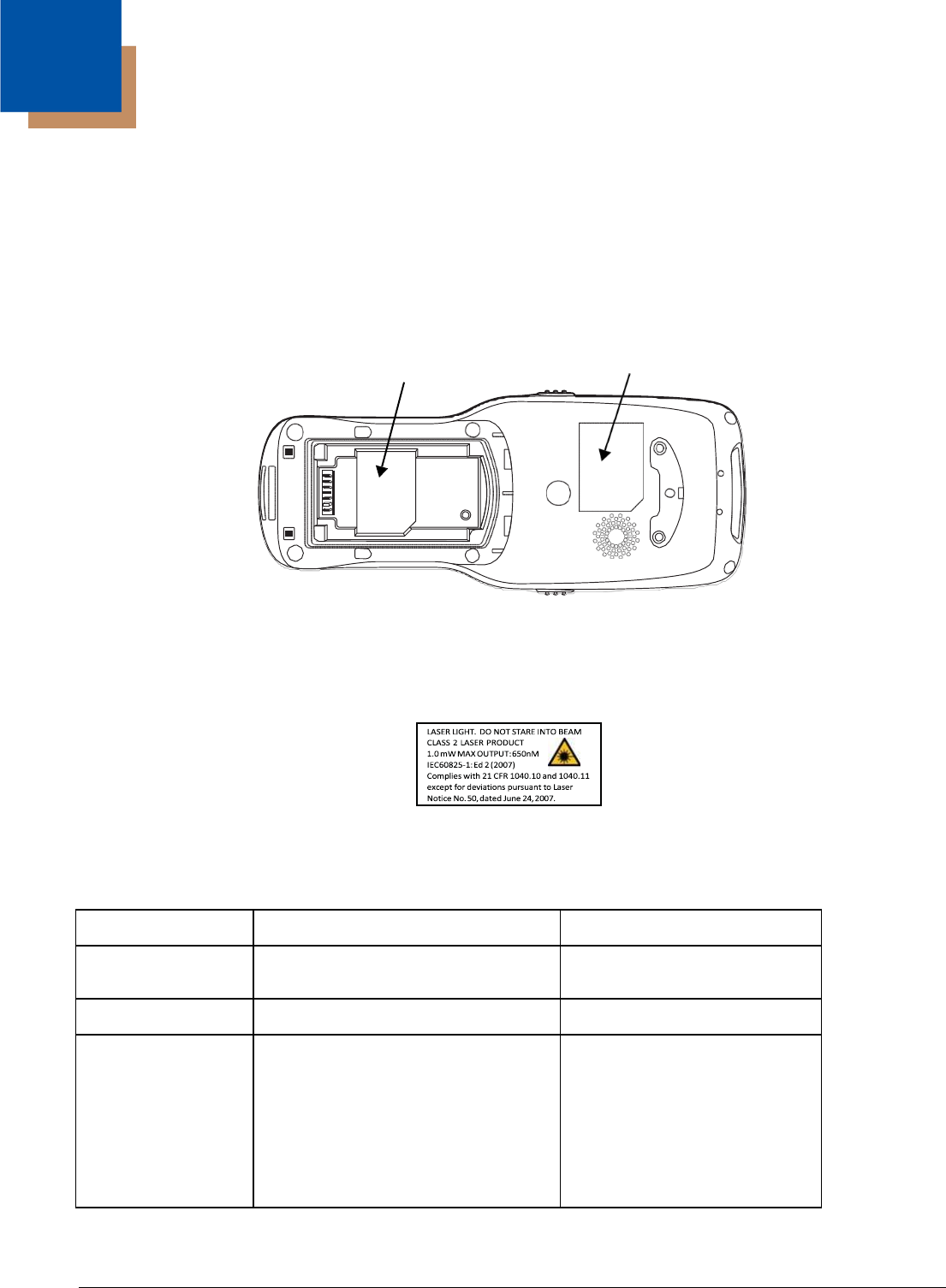
Laser Safety Label
If the following label is attached to your product, it indicates that the product contains an engine with a
laser aimer:
N4313-TTL Safety & RF Approvals by Country:
Country Safety RF (Radio)
U.S.A. UL60950-1 FCC Part 15, Sub part B, Sub
part C, Sub part E
Canada* C-UL CSA C22.2 No. 60950-1-07 ICES-003, RSS 247
European IEC 60825-1:2007 EN55022
(CISPR
22)
Class B
Community
IEC62471:2008
EN60950-
EN55024:2010
EN300 328
1:2006+A11:2009+A1:2010+A12:2011 EN300 440-2
EN301 489-1
EN301 489-17
EN301 893
EN62311
EN62209-2
* Does not apply to N4313-TTL laser engine.
1 - 1
Compliance
Label Laser
Light
Label
1

R&TTE Compliance Statement—802.11a/b/g/n and/or Bluetooth
Dolphin RF terminals are in conformity with all essential requirements of the R&TTE Directive (1999/5/
EC).
This product is marked with
2200
!
in accordance with the Class II product requirements specified
in the R&TTE Directive, 1999/5/EC. The equipment is intended for use throughout the European
Community; PAN European Frequency Range: 2.402–2.480 GHz.
Restrictions for use in France are as follows:
•Indoor use: Maximum power (EIRP*) of 100 mW for the entire 2.400–2.4835 GHz
•Outdoor use: Maximum power (EIRP*) of 100 mW for the 2.400–2.454 GHz band & maximum power
(EIRP*) of 10 mW for the 2.454–2.483 GHz band.
Frequency band 5180-5320 MHz is restricted to indoor use only.
The CE Mark on the product indicates that the system has been tested to and conforms with the
provisions noted within the 2004/108/EC Electromagnetic Compatibility Directive and the 2006/95/
EC Low Voltage Directive. Honeywell shall not be liable for use of our product with equipment (i.e.,
power supplies, personal computers, etc.) that is not CE marked and does not comply with the Low
Voltage Directive.
For further information, contact:
Hand Held Products Europe B.V.
Nijverheidsweg 9-13
5627 BT Eindhoven
The Netherlands
Warning! To prevent possible hearing damage, do not listen at high volume levels for long periods.
CB Scheme
Certified to CB Scheme IEC 60950-1.
FCC RF Radiation Exposure Statement
This equipment complies with FCC RF radiation exposure limits set forth for an uncontrolled environment.
Dolphin RF Terminal—802.11a/b/g/n and/or Bluetooth
This device complies with Part 15 of the FCC Rules. Operation is subject to the following two conditions:
(1) this device may not cause harmful interference, and (2) this device must accept any interference
received, including interference that may cause undesired operation.
This equipment has been tested and found to comply with the limits for a Class B digital device pursuant
to Part 15 of the FCC Rules. These limits are designed to provide reasonable protection against harmful
interference in a residential installation. This equipment generates, uses, and can radiate radio frequency
energy and, if not installed and used in accordance with the instructions, may cause harmful interference
to radio communications. However, there is no guarantee that interference will not occur in a particular
installation. If this equipment does cause harmful interference to radio or television reception, which can
be determined by turning the equipment off and on, the user is encouraged to try to correct the
interference by one or more of the following measures:
•Reorient or relocate the receiving antenna.
•Increase the separation between the equipment and receiver.
1 - 2

•Connect the equipment into an outlet on a circuit different from that to which the receiver is connected.
•Consult the dealer or an experienced radio/TV technician for help.
If necessary, the user should consult the dealer or an experienced radio/television technician for
additional suggestions. The user may find the following booklet helpful: “Something About Interference.”
This is available at FCC local regional offices. Our company is not responsible for any radio or television
interference caused by unauthorized modifications of this equipment or the substitution or attachment of
connecting cables and equipment other than those specified by our company. The correction is the
responsibility of the user. Use only shielded data cables with this system.
In accordance with FCC 15.21, changes or modifications not expressly approved by the party responsible
for compliance could void the user’s authority to operate the equipment.
This device and its antenna must not be co-located or operating in conjunction with any other
antenna or transmitter. To maintain compliance with FCC RF exposure guidelines for body-
worn operation, do not use accessories that contain metallic components.
CAUTION! This equipment may generate or use radio frequency energy. Changes or modifications
to this equipment may cause harmful interference unless the modifications are expressly approved in
the instruction manual. The user could lose the authority to operate this equipment if an unauthorized
change or modification is made.
Canadian Compliance
This radio transmitter has been approved by Industry Canada to operate with the antenna types listed
below with
the maximum permissible gain and required antenna impedance for each antenna type indicated.
Antenna types not included in this list,
having a gain greater than the maximum gain indicated for that type, are strictly prohibited for use with
this device.
Under Industry Canada regulations, this radio transmitter may only operate using an antenna of a type
and maximum
(or lesser) gain approved for the transmitter by Industry Canada. To reduce potential radio interference to
other users, the antenna type and its gain should be so chosen that the equivalent isotropically radiated
power (e.i.r.p) is not more than that necessary for successful communication.
This device complies with Industry Canada license-exempt RSS standard(s).
Operation is subject to the following two conditions:
(1)this device may not cause interference,
and (2) this device must accept any interference, including interference that may cause undesired
operation of the device.
Le présent émetteur radio a été approuvé par Industrie Canada pour fonctionner avec les types
d'antenne énumérés ci-dessous et ayant un gain admissible maximal et l'impédance requise pour chaque
type d'antenne. Les types d'antenne non inclus dans cette liste, ou dont le gain est supérieur au gain
maximal indiqué, sont strictement interdits pour l'exploitation de l'émetteur.
Conformément à la réglementation d'Industrie Canada, le présent émetteur radio peut fonctionner avec
une antenne d'un type et d'un gain maximal (ou inférieur)
approuvé pour l'émetteur par Industrie Canada. Dans le but de réduire les risques de brouillage
radioélectrique à l'intention des autres utilisateurs, il faut choisir le type d'antenne et son gain de sorte
que la puissance isotrope rayonnée équivalente (p.i.r.e.) ne dépasse pas l'intensité nécessaire à
l'établissement d'une communication satisfaisante.
Le présent appareil est conforme aux CNR d'Industrie Canada applicables aux appareils radio exempts
de licence.
L'exploitation est autorisée aux deux conditions suivantes :
(1)l'appareil ne doit pas produire de brouillage, et (2) l'utilisateur de l'appareil doit accepter tout brouillage
radioélectrique subi, même si le brouillage est susceptible d'en compromettre le fonctionnement.
1 - 3

Cover
Locks
Main
Batt
Getting Started
Out of the Box
Verify that your carton contains the following items:
• Dolphin 6510 mobile computer (the terminal)
• Battery pack (3.7v, Li-Ion)
• AC power supply (KSAS0120500200D5; Input: 100-240V AC, 50/60Hz 0.4 Amps; Output: 5 Volts DC, 2.0 A)
• Localized plug adapters
Note: Be sure to keep the original packaging in case you need to return the Dolphin terminal for service; see
Customer Support on page 12-1.
Initial Setup for Dolphin 6510 Terminals
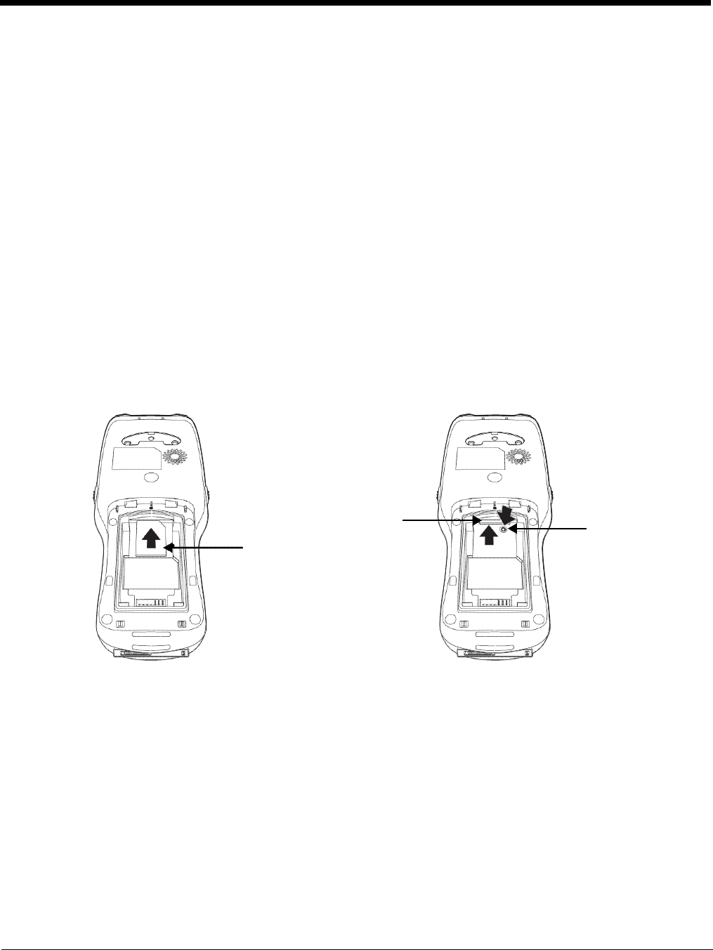
Step 1. Install the Battery
The Dolphin 6510 is shipped with the battery packaged separate from the unit. Follow the steps below to
install the battery.
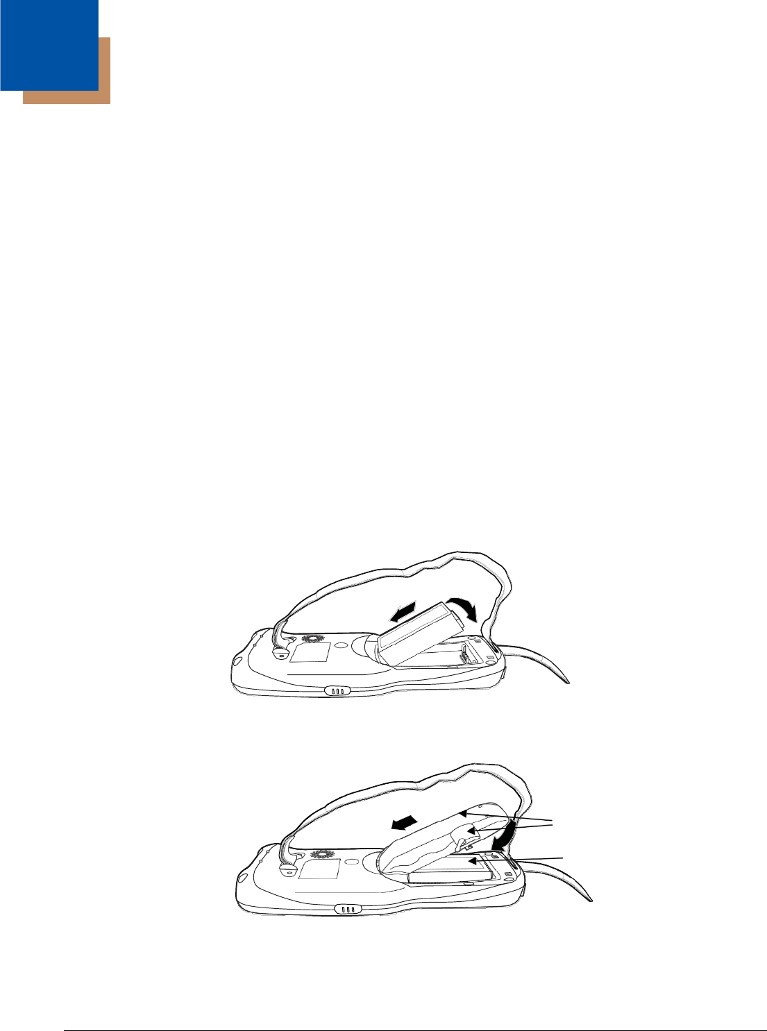
1. Release the strap making it convenient to reach the cover.
2. Remove the battery compartment cover by turning the cover locks upward and removing the cover.
3. Insert the battery into the battery well with the labels facing upward.
4. Replace the cover with a hinging motion and turn the locks downwards.
Note: The battery door must be installed prior to booting the unit.
5. Replace the hand strap.
2 - 1
2
!
We recommend use of Honeywell Li-Ion battery packs. Use of any non-Honeywell battery may result in damage not
covered by the warranty.
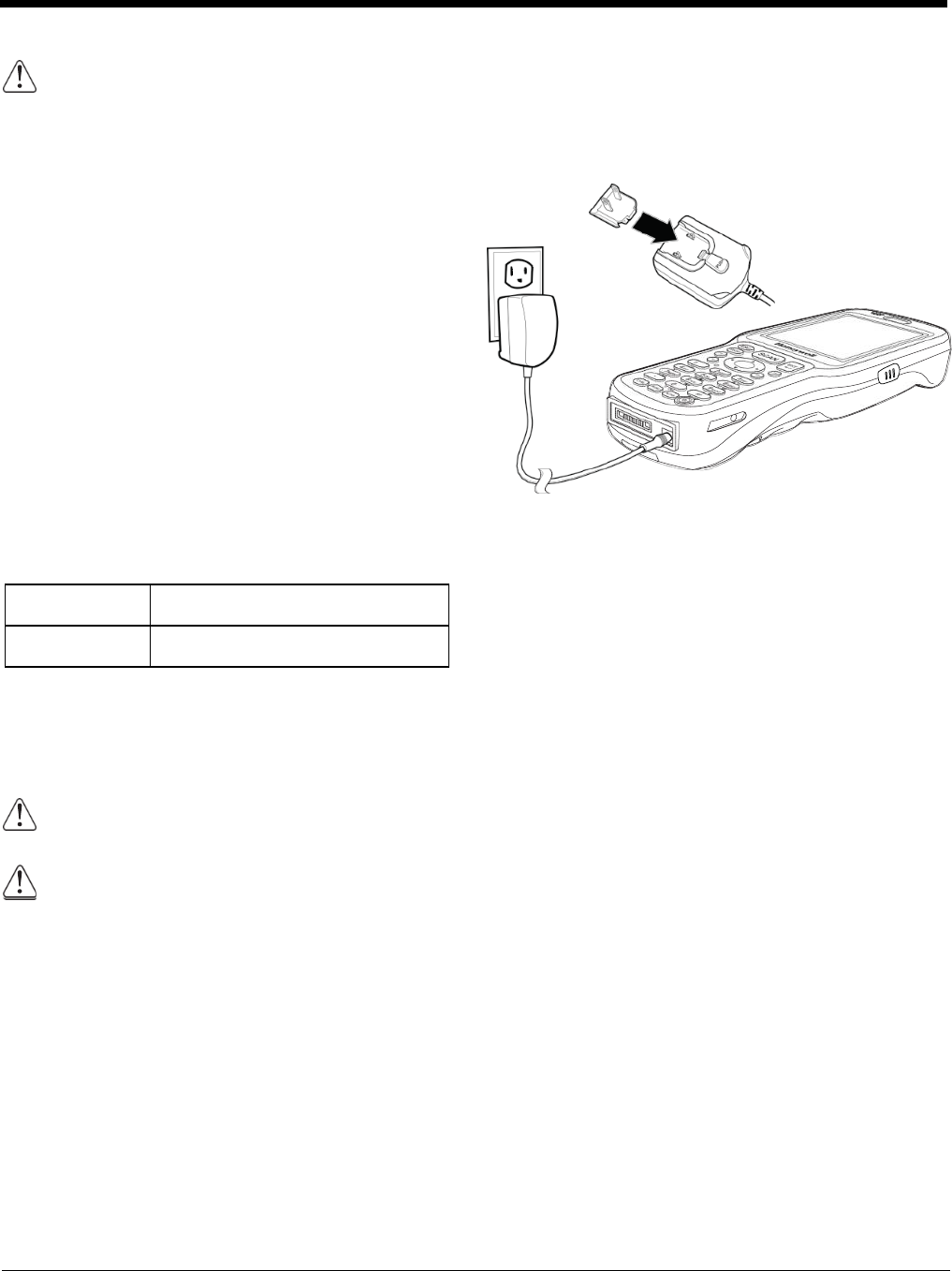
Step 2. Charge the Batteries
Dolphin 6510s ship with the battery pack
significantly discharged of power. Charge the
battery pack with the Dolphin charging cable until
the LED turns green (red while charging). The
average charge time for a fully depleted battery is
7 1/2 hours. It takes less time if the battery has
some charge.
1. Attach the appropriate plug adapter to the
plug of the power cable.*
2. Insert the plug into the appropriate power
source.
3. Plug the Dolphin power cable into the DC
Power Jack (see page 3-7) on the bottom end
of the unit.
Important:
Removing the battery from the terminal erases
all non-persistent memory.
LED Indicators
Red LED On Charging
Green LED On Battery is fully charged
*This power cable can also be used to power the
Dolphin 6510 while in the Dolphin HomeBase
(Model 6500-HB)/eBase (Model 6500-EHB)
Device (see page 10-1).
We recommend use of Honeywell peripherals, power cables, and power adapters compiled with
L.P.S. Use of any non-Honeywell peripherals, cables, or power adapters may cause damage not
covered by the warranty.
Ensure all components are dry prior to mating terminals/batteries with peripheral devices. Mating
wet components may cause damage not covered by the warranty.
2 - 2
1
2
3
The power adapter on the power cable converts the voltage from the power source to 5 volts DC. Only
power adapter cables from Honeywell convert the voltage appropriately. The power cable contains a plug
adapter for each geography (US, UK, EU, etc.).
Power Adapter
Plug Adapter
Power Cable
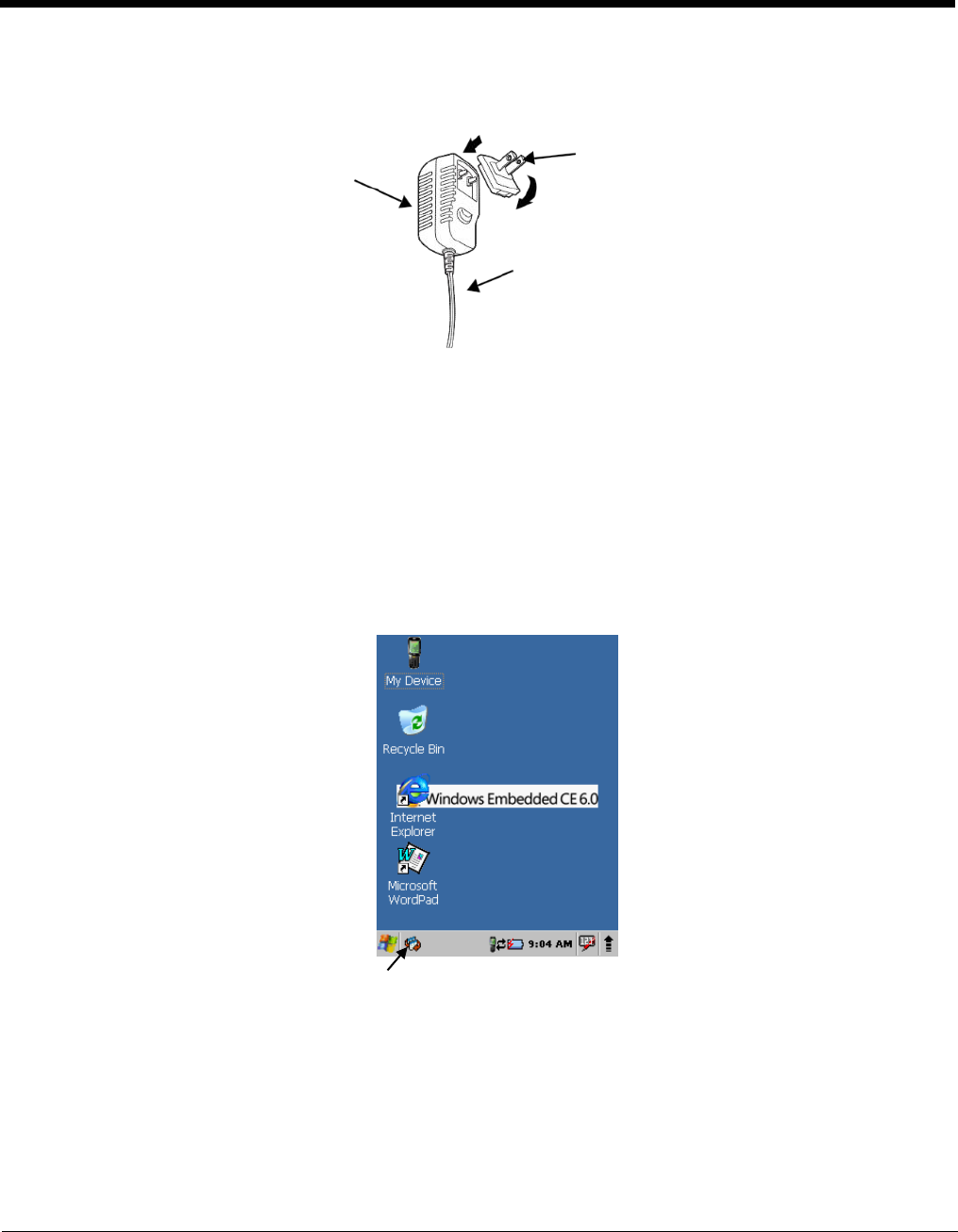
Step 3. Boot the Terminal
The terminal begins booting as soon as power is applied and runs by itself. Do NOT press any keys or
interrupt the boot process.
When the boot process is complete, the Desktop appears, and the terminal is ready for use.
Desktop
Note: You can access the Desktop any time by tapping the Change Views icon in the command bar and selecting
Desktop on the popup menu.
Tap to change views
2 - 3
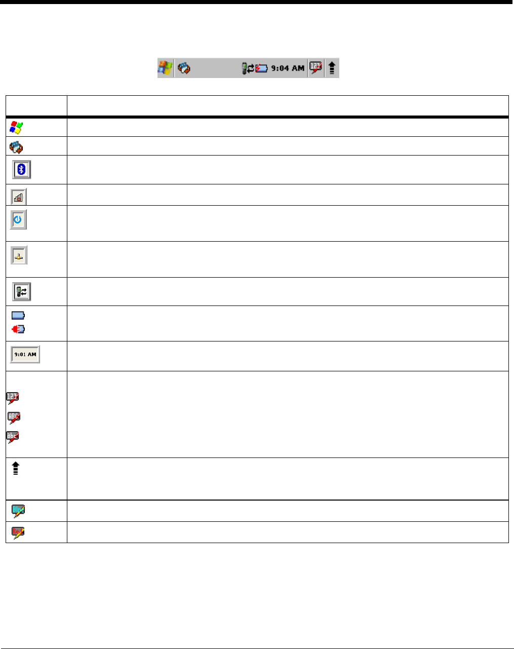
Command Bar Icons
The command bar, located at the bottom of application screens, provides access to many system
functions and programs.
Icon
Meaning
Opens the Start menu.
Tap to change views between open applications or to return to the desktop.
Accesses the Bluetooth radio. Double tap this icon to open the Bluetooth Handler (see page 8-1).
Shows signal strength of WiFi radio. (A red X indicates it is not currently associated to an AP.)
Double tap to configure your WLAN Secure Wireless Client. For complete configuration
instructions, download the Honeywell Secure Wireless (SWC) Client User’s Guide from
www.honeywellaidc.com.
Indicates Ethernet communications. When the terminal is undocked, no icon appears. When it is
docked without a cable, the icon has a red X through it. When docked with a cable connected, this
icon displays.
Indicates that the USB communication cable is connected. Double tap to display USB status
window.
Indicates the status of battery power. Double tap to open the Power control panel setting.
When this icon shows a red power plug, it indicates the device is using external power.
Displays the current time. Double tap to change the time and date.
28-key keypad - Indicates whether the keypad is standard alpha (uppercase and lowercase), all
caps alpha, or in numeric mode. Press the ALPHA button on the keypad to switch modes.
52-key keypad - Press the SFT key twice in rapid succession to toggle between upper and
lowercase as indicated by the icon. Pressing the SFT key once temporarily toggles for the next
typed key and then reverts back. You can also change from upper/lowercase by selecting the
“ABC”/”abc” indicator and selecting CAP on the keyboard that displays. Pressing a number key
results in a number appearing in the application. Pressing SFT key once and typing a number on
the keypad results in a special character appearing in the application.
The up arrow allows you to turn the Wireless LAN and Bluetooth connection on or off. It also
allows you to toggle between the Keyboard and Transcriber. When Keyboard is selected, a
keyboard is displayed so you can tap text and number keys. Transcriber recognizes handwriting
and symbols entered using the stylus.
Indicates Blue mode.
Indicates Red mode.
2 - 4

Using the Stylus
The terminal comes with a stylus included in a loop on the hand strap. Use this stylus (or your finger) to
select or enter information on the touch screen. The stylus functions as a mouse; generally, a tap is the
same as a click.
Tap
Tap the touch screen once or double tap to open menu items and select options.
Drag
Hold the stylus on the screen and drag across the screen to select text and images.
Tap & hold Tap and hold the stylus on an item and a pop-up menu appears. On the pop-up menu, tap
the action of the task you want to perform.
Use of objects, such as paper clips, pencils, or ink pens on the touch screen can damage the input
panel and may cause damage not covered by the warranty.
For more information about the touch screen, see Touch Screen Display on page 3-2.
Selecting Programs
Tap Start > Programs. To open a program, tap the icon on the menu.
Pop-Up Menus
You can quickly choose an action for an item using the pop-up menus.
1. Tap and hold the stylus on the item name. The pop-up menu appears.
2. Lift the stylus and tap the action you want to perform.
The contents of pop-up menus change according to the program you are using.
Using Windows Explorer
Use Windows Explorer to navigate through the files on your system. On the desktop, double tap the My
Device icon and Windows Explorer opens to the root level.
Move files by tapping and holding on the file, then tapping Cut, Copy or Paste on the pop-up menus that
appear.
2 - 5

Hardware Overview
Dolphin 6510 terminals include a number of standard terminal configurations as well as charging and
communication peripherals and accessories to maximize the efficiency of your application setting.
Standard Terminal Configurations
There are two standard Dolphin 6510 configurations: WPAN only and WPAN/WLAN. Both configurations
include the following options; however, the WPAN/WLAN configuration has both a Bluetooth radio and an
802.11a/b/g/n radio.
2 –6
Dolphin 6510 WPAN and WPAN/WLAN
•Microsoft Windows CE 6.0
•
TI Cortex-A8 1GHz
•
512MB RAM X 1 GB (non-volatile) Memory
•28-key numeric keypad (alpha shifted) and 52-
key full alpha and numeric keypad
•
3.5” transflective active matrix 65k color LCD
display with backlight, QVGA (240 x 320)
•
Li-Ion battery: 3.7V / 3300mAh / 12.2 Wh
•
N560x image engine with laser aiming or
N4313 laser engine
•
(WPAN) - Bluetooth radio
•
(WPAN/WLAN) - Bluetooth and
802.11a/b/g/n radio
•
Dolphin power cable (included with each
Dolphin 6510)
3
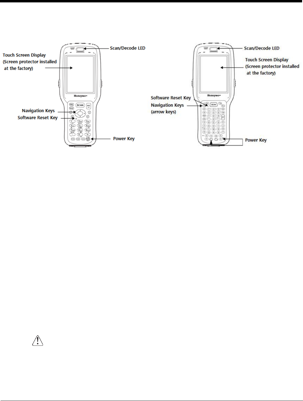
Front Panel Features
(28-key keypad (numeric)
(52-key keypad (full alphanumeric)
Scan/Decode LED
The LED lights red when you press the Scan trigger in scanning applications.
The LED lights green when a scanned bar code is successfully decoded.
The LED lights red while the main battery is charging.
The LED lights green when the main battery charging is completed.
The LED lights blue or red during soft and hard resets.
The LED is user-programmable.
Keypad
28-key numeric keypad (alpha shifted) and 52-key full alphanumeric keypads are available.
Microphone
The integrated microphone can be used for audio recording.
Touch Screen Display
The display is a 3.5” transflective active matrix, 65k color LCD display with a backlight, QVGA
(240 x 320 resolution); see Display Backlight on page 3-3. The touch panel is a 4-wire analog
resistive touch.
Dolphin 6510s ship with a screen protector already installed over the touch screen lens
to help prevent damage to the touch screen. Do NOT remove this screen protector before
initial use. Honeywell recommends using screen protectors, especially for applications
that require high volume interfacing with the touch screen. For more information, see
Using Screen Protectors on page 3-3. You can purchase additional screen protectors by
contacting your Honeywell sales representative.
2 - 7
For touch screen input, use the stylus included with the terminal or your finger. The method
you choose depends on which one is most appropriate for your application. While there is a
great deal of variation in different applications, you generally achieve greater accuracy with the
stylus for buttons or icons that are close together.
Use of objects, such as paper clips, pencils, or ink pens on the touch screen can damage
the input panel and may cause damage not covered by the warranty.
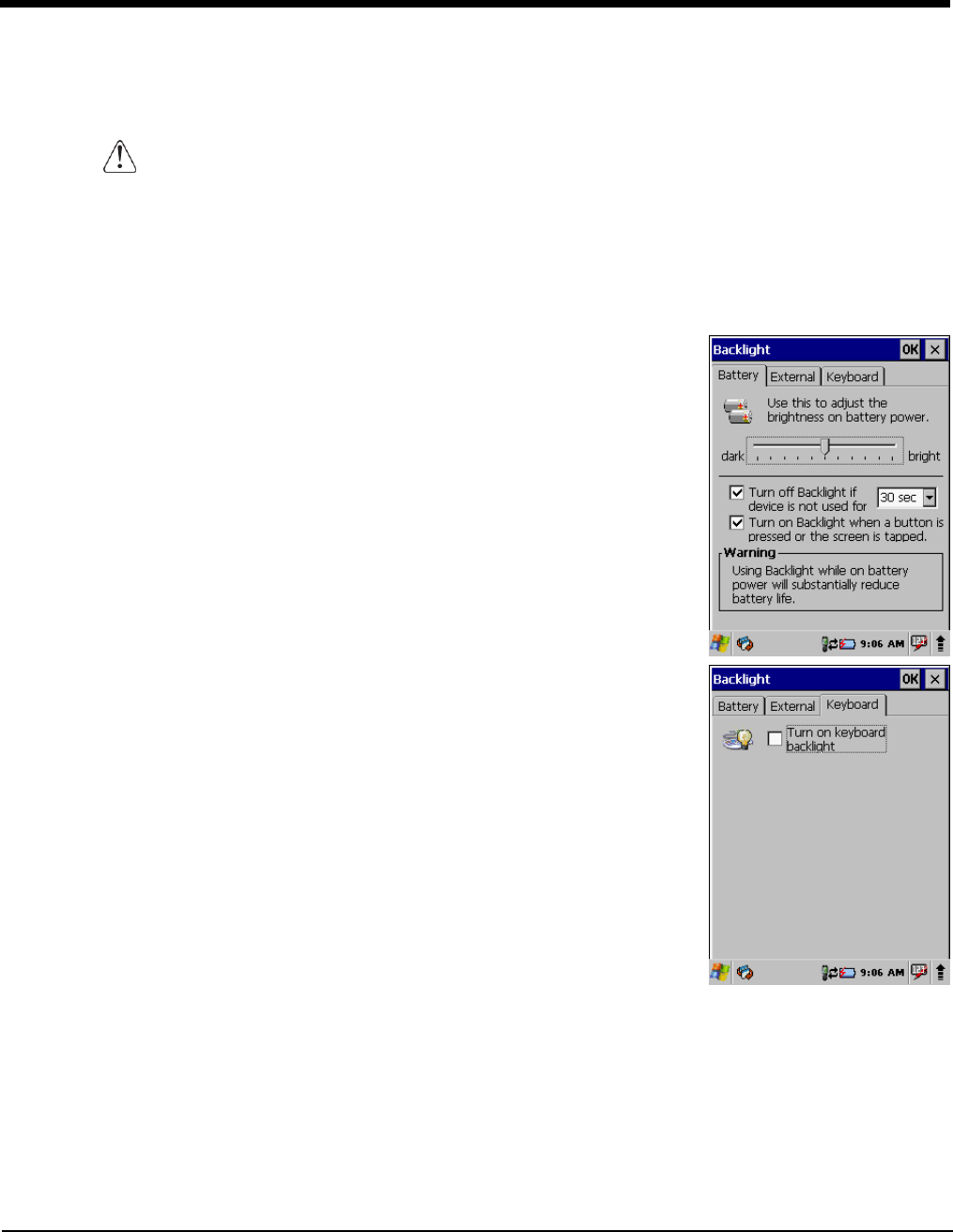
Display Backlight
The intensity of the backlight of the touch screen display may be changed, and the backlight may be
programmed to turn off after the terminal has been idle for a specified period of time.
To adjust the intensity of the backlight while on battery power, tap Start > Settings > Control Panel >
double tap Backlight.
Screen Backlight - Battery/External Power
Move the slider to adjust the screen backlight while on battery power.
You may turn the screen backlight off if the device is not used for a
designated period of time by checking the option and designating the
desired time period.
You may also turn on the screen backlight when a button is pressed or the
screen is tapped by selecting the appropriate checkbox.
Note: Using the backlight option while on battery power substantially reduces
battery
life.
You may make the same changes when on external power by tapping the
External tab.
Keyboard Backlight
To turn on the keypad backlight, check the checkbox.
The duration of backlight of keypad synchronizes with LCD backlight’s.
Using Screen Protectors
Honeywell defines proper use of the terminal touch panel display as using a
screen protector and proper stylus. Screen protectors maintain the ongoing
integrity (i.e., prevent scratching) of the touch panel, which is why their use is
recommended for applications that require a high to medium level of interface
with the touch panel.
Honeywell continues to advocate the use of screen protectors on all Dolphin terminals. We recommend
implementing a screen protector replacement program to ensure that screen protectors are replaced
periodically when signs of damage/wear are noticeable. For general use, we recommend replacing the
screen protector every thirty (30) days. However, replacement cycles vary according to the average level
of touch panel use in your application.
2 - 8
Replacement screen protectors can be purchased directly from Honeywell. Contact a Honeywell sales
representative for details.
Honeywell also mandates use of a proper stylus, which is one that has a stylus tip radius of no less than
0.8mm. Use of the Honeywell stylus included with the terminal is recommended at all times.
Honeywell’s warranty policy covers wear on the touch panel for the first 12 months provided that a screen
protector is applied and an approved stylus is used for the 12-month duration covered by the warranty.
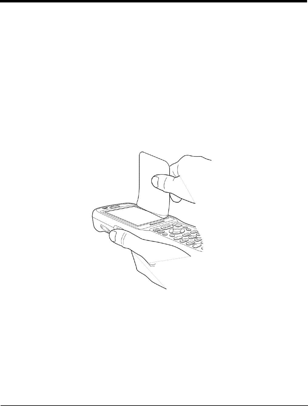
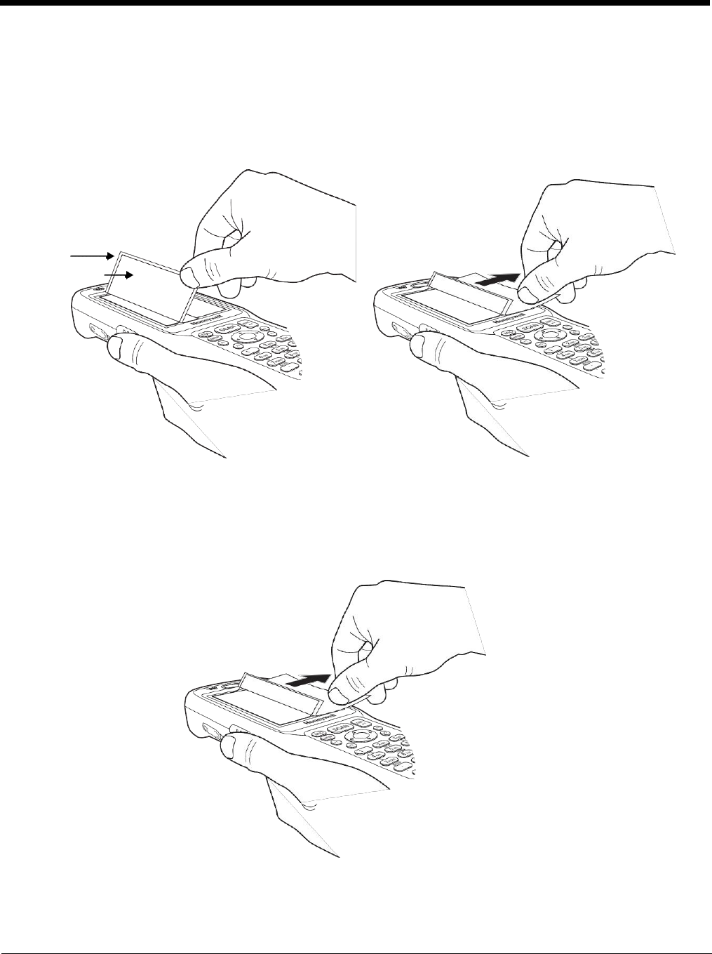
Removing the Screen Protector
Dolphin 6510s ship with a touch screen protector already installed. To replace the screen protector, you
must remove the one already installed.
1. Press the red Power button to suspend the 28-key unit or press the Blue then Z (Power) keys to
suspend the 52-key unit.
2. Using a strong, flat, plastic card (e.g., credit card) wedge the edge of the card under the existing
screen protector. Catch the edge of the screen protector and pull it up and away from the touch
panel.
Note: If you have one, you can also use the small plastic squeegees designed for touch panels.
3. Wipe the screen with a clean, non-abrasive, lint-free cloth.
Note: Use ionized air, if available, to blow additional dirt or particles off the touch panel.
Installing Your Screen Protector
When installing a new screen protector, use a flat plastic card (e.g., credit card) to apply the screen
protector smoothly and remove any air bubbles.
Note: If you have one, you can also use the small plastic squeegees designed for touch panels.
1. Press the red Power button to put the terminal in Suspend Mode on the 28-key Dolphin 6510 or
press the Blue then Z (Power) keys on the 52-key Dolphin 6510.
3 - 4
2. Clean the touch panel thoroughly with a clean, non-abrasive, lint-free cloth. Make sure nothing is on
the touch panel.
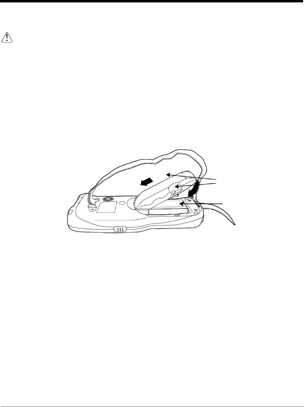
3. Release the left edge of the backing paper on the screen protector.
4. Align the exposed edge of the screen protector along the left edge of the touch panel.
Make sure that it lies flush with edges of the touch panel.
Backing
Paper
Screen Protector
Note: To reposition the screen protector, lift up gently and reapply.
5. Use the card on top of the screen protector to smooth it out as you pull on the backing paper.
3 - 5
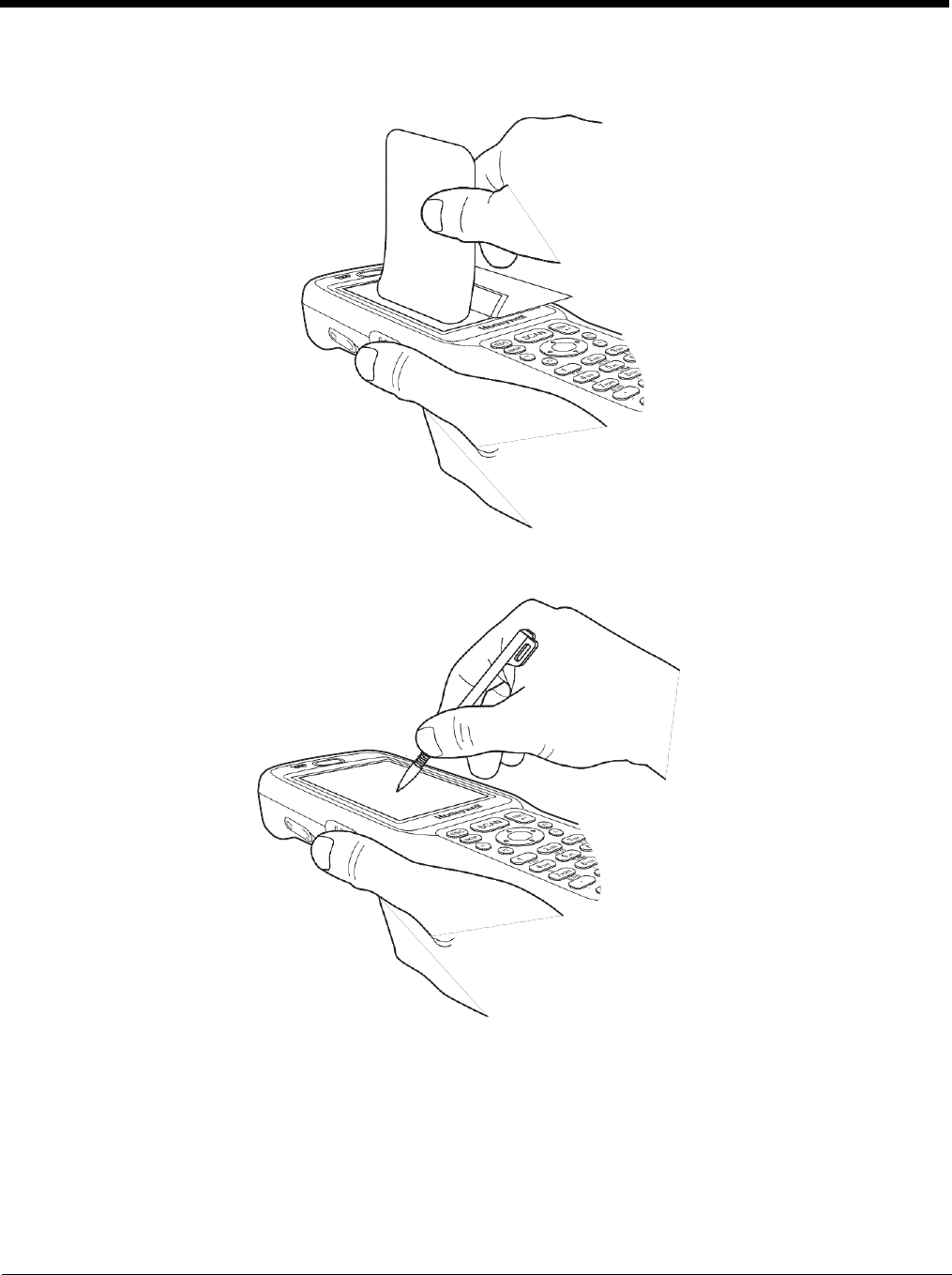
6. Pull smoothly and evenly from left to right until the screen protector is applied. Press gently but
firmly. Use the card as necessary to smooth out any air pockets or bumps after application.
7. Press the Power key to wake the terminal and check the touch panel with the stylus.
8. Verify that the screen accepts input from the stylus as usual. If not, re-apply the screen protector.
9. Press the red Power button to put the terminal back in Suspend Mode on the 28-key Dolphin 6510
or press the Blue then Z (Power) keys on the 52-key Dolphin 6510.
10. Clean the surface of the screen protector with a clean, non-abrasive, lint-free cloth.
11. Press the Power key to wake the terminal again.
3 - 6
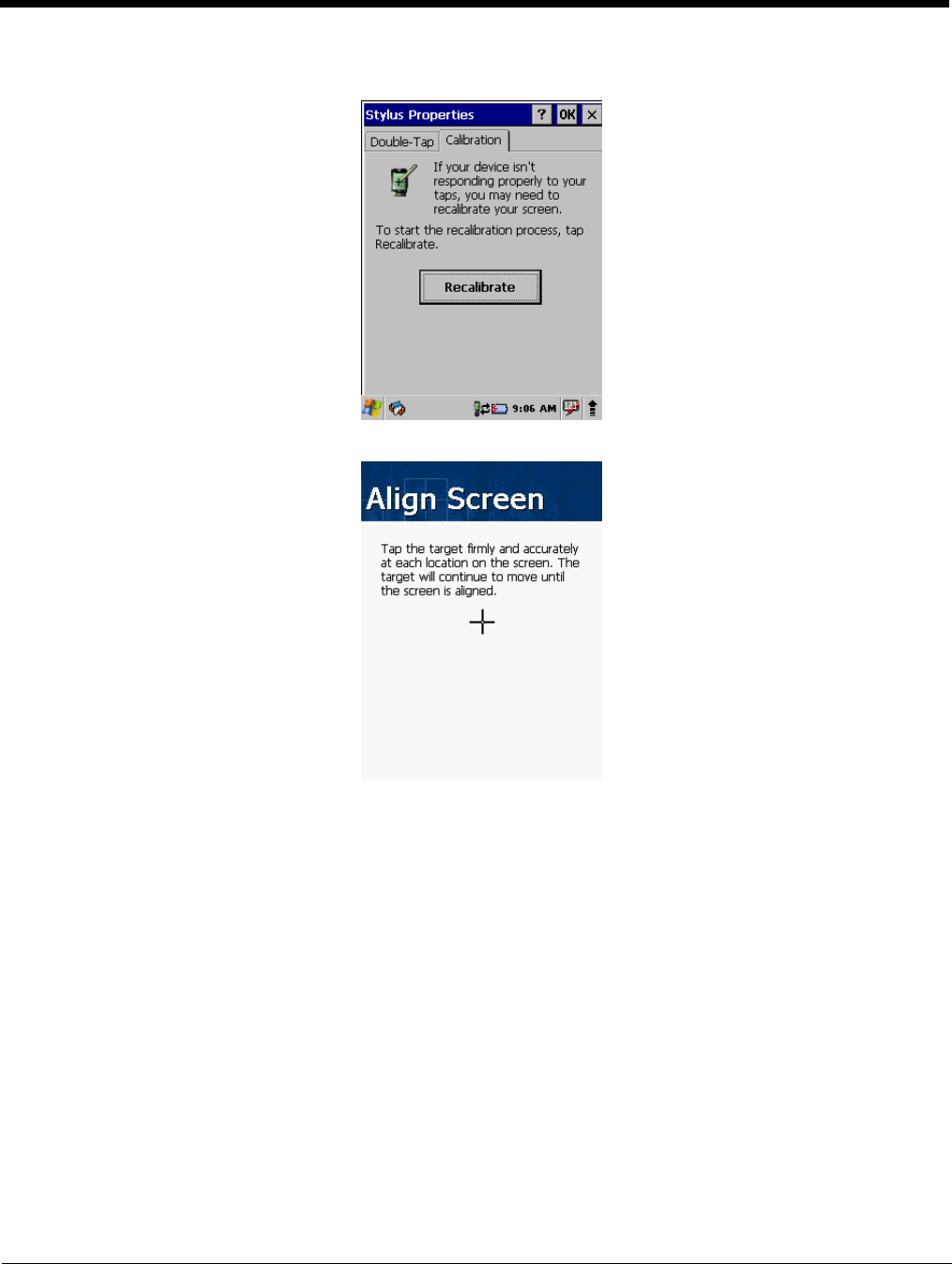
12. For maximum performance, recalibrate the screen. Tap Start > Settings > Control Panel > double
tap Stylus > Calibration tab.
13. Tap Recalibrate and follow the instructions on the screen.
3 - 7
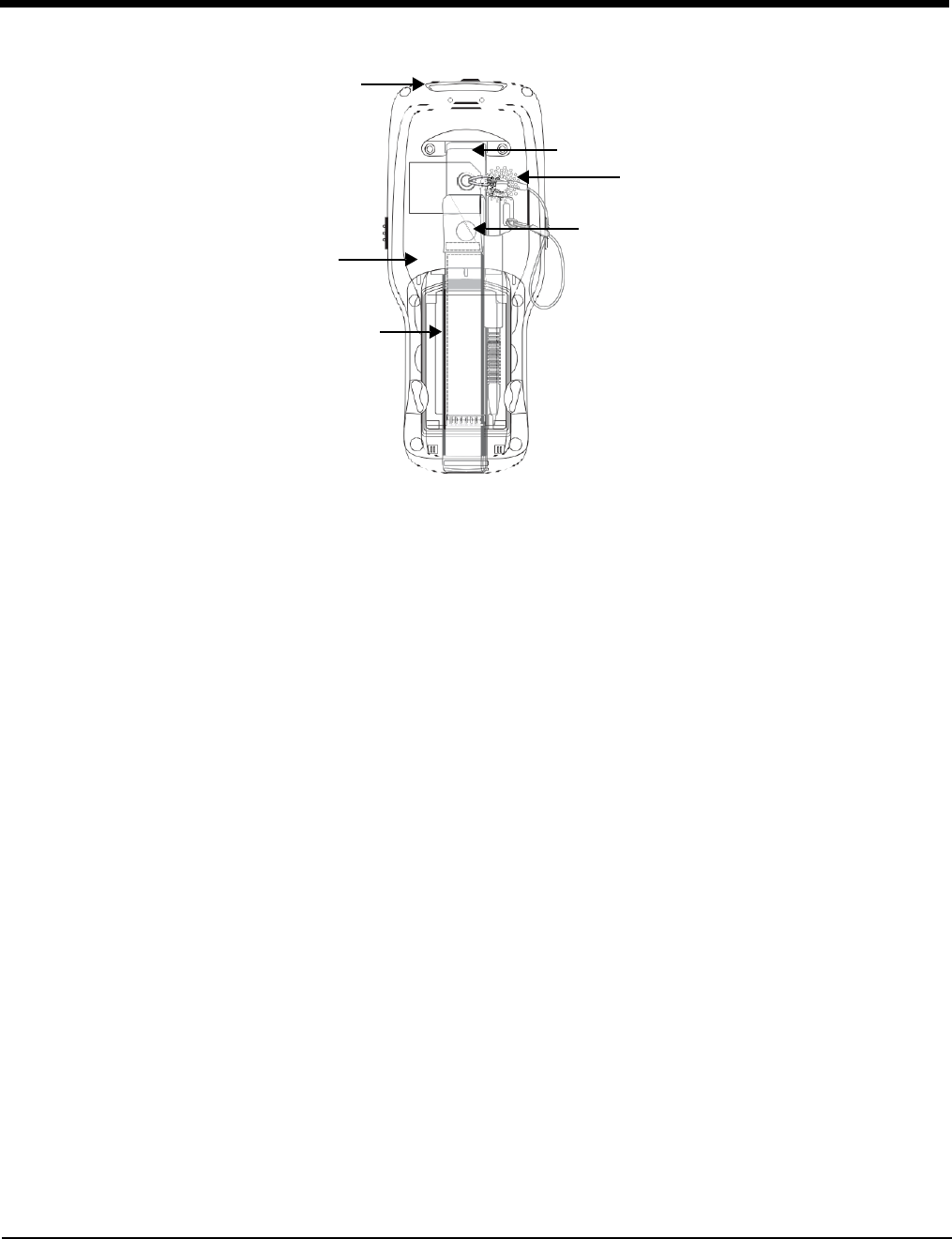
Back Panel Features
Image Engine Window
Hand Strap (with Stylus)
Speaker
Finger
Saddle
Rear Scan Button
Installed Battery
Hand Strap
The Dolphin 6510 comes with an adjustable, elastic hand strap. The strap is attached to the
device with the two small screws. It is threaded through the slot on the bottom of the back of
the unit.
Keep in mind that the hand strap covers the battery. When you want to replace the battery, you
will need to adjust the hand strap accordingly.
Rear Scan Button
The Dolphin 6510 has a Scan button conveniently located on the back of the unit. This button
works like the SCAN button located on the front of the unit. Pressing this button can also
resume a suspended device.
Finger Saddle
This is a slightly depressed and angled area of the back housing that is designed to cradle or
“saddle” your finger while holding the terminal. This unique ergonomic design makes the
terminal comfortable to hold and helps prevent you from accidentally dropping the terminal.
Installed Battery
For information about installing the battery, see Changing the Main Battery Pack on page 3-13
For information about battery power, see Battery Power on page 3-12.
Speaker
The integrated speaker sounds audio signals as you scan bar code labels and enter data, but
emits no ambient noise on system activity (i.e., processor, memory access, radio traffic, etc.).
The speaker can also be used for playing sounds (e.g., WAV or MP3 files).
The speaker meets the following SPL levels at 40cm:
• 500Hz–67db
•
1KHz–72db
3 - 8
Stylus
•
4KHz–72db
Dolphin 6510 terminals ship with a stylus inserted in a loop on the hand strap. Store the stylus
in the hand strap when you’re not using it; see Using the Stylus on page 2-5.
Installing Memory Cards
The Dolphin 6510 supports Secure Digital (SD) memory cards from 512MB up to 8GB in capacity. The
recommended SD cards are 2GB and 4GB ATP®-brand, which have been tested for reliability. You can
purchase these SD cards by contacting your Honeywell sales representative.
To install an SD card:
1. Remove the battery door on the back of the unit.
2. Remove the battery.
3. Insert the SD card with the label facing upward by pressing down the small pin and sliding the SD
card into the SD card connector until you feel it lock into position. The notch on the SD card should
be in the upper-right hand corner.
Note: If your unit has trouble reading the SD card, the SD card may not have been inserted correctly. If depressing
the small pin allows the card to eject, the card was not properly inserted and “locked in.”
SD Card
SD Card Pin
4. Replace the battery and battery door.
5. Tap the Power or SCAN key to resume operation.
6. To verify that the operating system recognizes the new memory card, open Windows Explorer and
navigate to My Device\Storage Card.
To remove an SD card:
1. Remove the battery door on the back of the unit.
2. Remove the battery.
3. Press the SD card towards the front of the terminal until you hear a click to confirm that it has
unlocked. The card will stops when it hits the pin.
4. Depress the small pin at the edge of the card. The card will pop out enough for you to grab its edge.
3 - 9
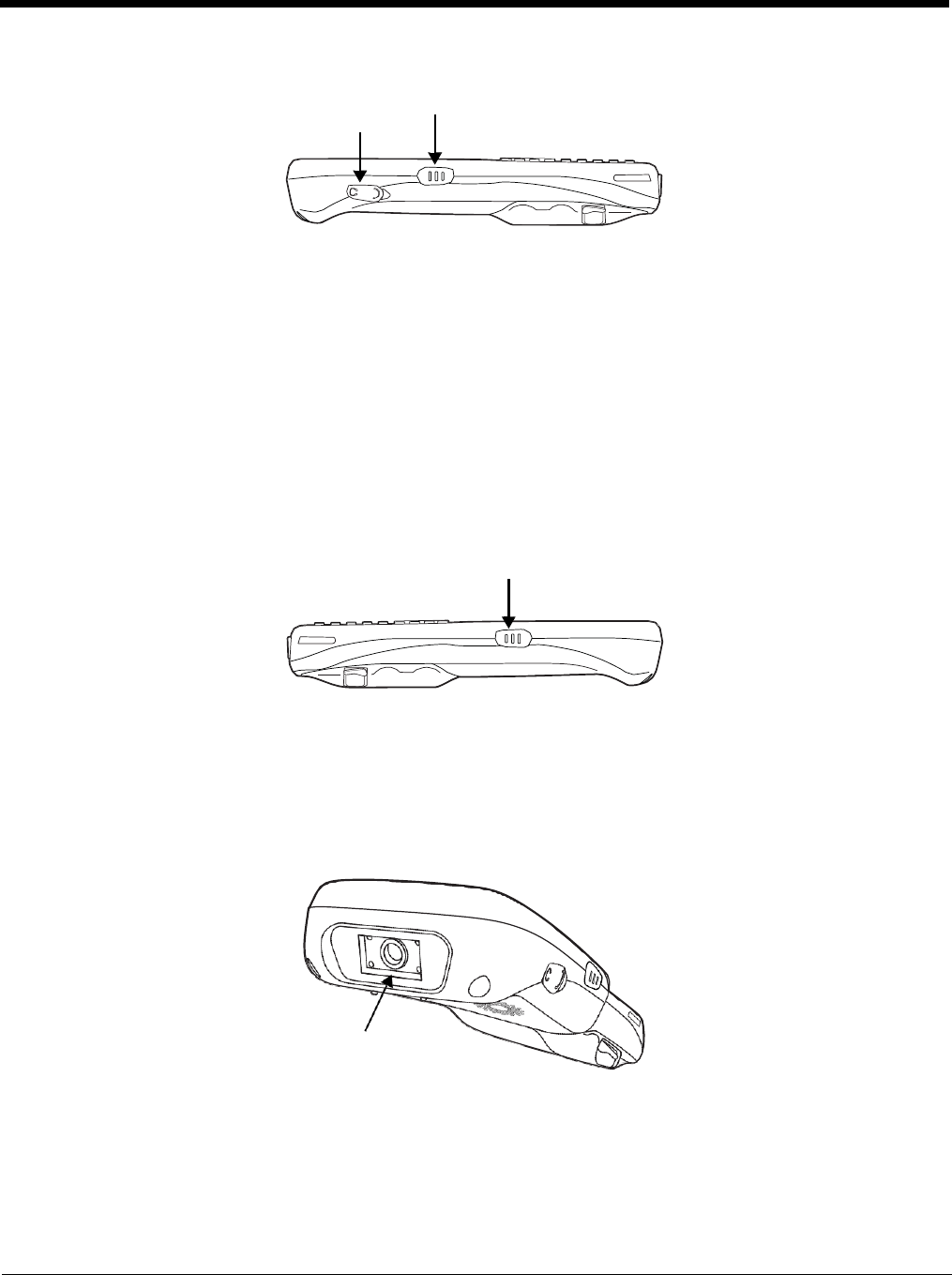
Left Side Panel Features
Side Button
Headset Jack
Side Button
There is a button like this on both side panels. You can use the Programs Buttons option in
the Control Panel to change the functionality of the side buttons.
Headset Jack
The rubber door on the right side panel provides access to the headset jack. This is a 2.5mm
audio jack that supports a headset with a mono speaker and microphone.
When closed, the side door seals the terminal from moisture and particle intrusion thus
preserving the terminal’s environmental rating.
Right Side Panel Features
Side Button
Side Button
There is a button like this on both side panels. You can use the Programs Buttons option in the
Control Panel to change the functionality of the side buttons.
Top Panel Features
Imager or Laser Aperture Window
Imager or Laser Aperture Window
The angled image engine reads and decodes most popular bar code symbologies and takes
images like a digital camera (imager engine only). For more information, see Using the Image
Engine on page 5-1 or see Using the Laser Engine on page 6-1.
3 - 10

Bottom Panel Features
I/O Connector
DC Power Jack
The DC power jack receives external power from the Dolphin power cable that is included in
the box with the terminal. When connected to the Dolphin power cable, the terminal is powered
and the main battery pack is charging.
I/O Connector
The I/O mechanical connector is designed to work exclusively with Dolphin 6510 peripherals
and cables. This connector powers the terminal, charges the main battery, and facilitates
communication. This connector supports full speed USB 1.1 communication (up to 12 Mbps)
and RS-232 communications with a maximum speed of 115Kbps and seven baud rate
settings.
Through this connector, you can communicate with a host workstation via Microsoft
ActiveSync; see ActiveSync Communication on page 7-3
The I/O connector supports the following signals:
•
DC IN
•
Transmitted Data
•
Request To Send
•
USB Host +5V
•
USB Host D+
•
USB Host D-
•
USB Host Detect
•
Clear To Send
•
Received Data
•
GND
•
RS-232 Shutdown
•
USB Client D+
•
USB Client D-
•
USB Client +5V
Note:
Signals referenced are for a DTE device.
Dolphin Peripherals/Accessories for the Dolphin 6510
The following items are sold separately and enhance your Dolphin 6510’s capabilities.
3 - 11
DC Power Jack

Dolphin HomeBase™ Device
This charging and communication cradle supports USB and RS-232 communication, enabling your
terminal to interface with the majority of enterprise systems. When a terminal is seated in a powered base,
its main battery pack charges in an average of 5 1/2 hours for a fully depleted battery. It takes less time
if the battery has some charge.
A spare battery may also be charged in the battery charging well behind the terminal.
For more information, see Dolphin HomeBase/eBase Device on page 9-1
Dolphin eBase™ Device
The Dolphin eBase is used to charge the main battery, to power the battery charging system in the
terminal, and can be used to communicate data from the terminal to a PC/laptop via the Ethernet port.
A spare battery may also be charged in the battery charging well behind the terminal.
For more information, see Dolphin HomeBase/eBase Device on page 9-1
Dolphin QuadCharger™ Device
The Dolphin QuadCharger device, a four-slot charging station for Dolphin Li-Ion battery packs, can
charge each battery in an average of 5 1/2 hours for a fully depleted battery. It takes less time if the
battery has some charge.
For more information, see Dolphin QuadCharger Device on page 10-1.
USB Communication Cable for the Dolphin 6510
The USB Communication Cable for the 6510 is used when communicating between the terminal and a
PC/laptop via the USB port. The cup-style 6510-USB cable slides onto the bottom of the device lining up
with the connector. The cable unit includes an opening for the power cable. See Connecting the USB
Charging/Communication Cable for the Dolphin 6510 on page 7-2.
Li-Ion Battery Packs
The Li-Ion battery pack provides the main power supply for the terminal. For more information, see Battery
Power on page 3-12.
For information on how to purchase these items, contact a Honeywell sales representative.
Battery Power
The intelligent battery technology inside the terminal features two types of battery power:
• The main battery pack on the back panel (see Main Battery Pack on page 3-13)
• The backup battery located inside the terminal (see Internal Backup Battery on page 3-15)
Both batteries work together to prevent data loss when the terminal is used over long periods of time.
Both batteries must be charged to full capacity before using the Dolphin 6510 for the first time!
Charge the main battery pack with the Dolphin charging cable until the LED turns green (red while
charging). The average charge time for a fully depleted main battery is 5 1/2 hours. It takes less time if
the battery has some charge.
3 - 12
Main Battery Pack
We recommend use of Honeywell Li-Ion battery packs. Use of any non-Honeywell battery may result in
damage not covered by the warranty.
The Dolphin 6510 has a Li-Ion 3.7V/3300 mAh/12.2 Wh battery pack.
The Li-Ion battery pack is the primary power source for the Dolphin terminal as well as the internal backup
battery.
Changing the Main Battery Pack
Before installing a battery pack, press the Power button on the 28-key Dolphin 6510 or press the Blue
then Z (Power) keys on the 52-key Dolphin 6510 to put the terminal in Suspend Mode (see page 3-16)
so that operations are suspended before removing the main power source. The Dolphin 6510 is shipped
with the battery separate from the unit. You will need to loosen the hand strap, remove the battery door,
insert the battery, and replace the battery door. Refer to the instructions included in Installing the Main
Battery section (page 2-1).
Note: The battery door must be installed prior to booting the unit.
Cover Locks
Main Battery
Charging Options
When the battery is installed in the terminal, you can use any of the peripherals listed below to charge the
battery.
• Dolphin HomeBase/eBase Device (see page 9-1)
• Dolphin Comm/Charge Cable; Connecting the USB Charging/Communication Cable for the Dolphin
6510 (see page 7-2) You may charge the device using the USB connection if you do not have a wall
adapter. There are two options that allow either 100mA or 500mA of current over the USB connection.
Access the option by selecting Start > Settings > Control Panel > Power > USB Charging.
To fully charge the Li-Ion battery before installing it in the terminal, use the
• Dolphin QuadCharger Device (see page 10-1) or insert the battery in the spare battery charging well
in the back of either the Dolphin HomeBase or Dolphin eBase.
Charging Time
The 3300mAh battery pack charges to full capacity in an average of 5 1/2 hours for a fully depleted
battery. It takes less time if the battery has some charge.
3 - 13
Managing Main Battery Power
Data and files saved on the Dolphin terminal may be stored in RAM memory; therefore, maintain a
continuous power supply to the terminal to help prevent data loss. When you remove a battery pack, insert
another charged battery pack in the Dolphin. If the main battery pack is low, insert the terminal into a
charging peripheral to power the terminal and begin recharging the battery.
Note: If the main battery is low and the terminal is in Suspend Mode, pressing the Power button does not wake
the Dolphin 6510 terminal; you must first replace the discharged battery with a fully charged battery or apply
A/C power to the terminal.
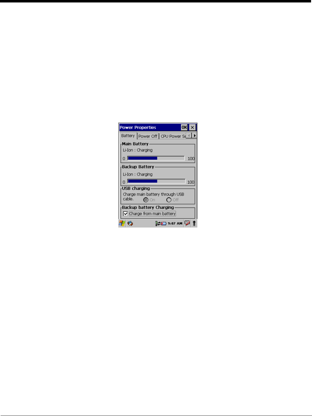
Checking Battery Power
Power icons appear in the command bar at the bottom of the window. Double tap on the battery icon to
open the Power Properties. The Battery tab opens displaying the charge status of both the main and
backup batteries.
Note: You can also check battery power by tapping Start > Settings > Control Panel > double tap Power.
Storage Guidelines
To maintain optimal battery performance, follow these storage guidelines:
• Avoid storing batteries outside the specified range of -4 to 140° F (-20 to 40°C) or in extremely high
humidity.
• For prolonged storage, it is recommended that the battery be at a 40% - 50% charge level, be removed
from the device, and stored in a controlled temperature environment. Following these
recommendations will maximize battery life.
Guidelines for Battery Pack Use and Disposal
The following are general guidelines for the safe use and disposal of batteries:
• We recommend use of Honeywell Li-Ion battery packs. Use of any non-Honeywell battery may pose a
personal hazard to the user.
• DO NOT attempt to charge damp/wet mobile computers or batteries. All components must be dry
before connecting to an external power source.
• Replace defective batteries immediately; using a defective battery could damage the Dolphin terminal.
• Never throw a used battery in the trash. It contains heavy metals and should be recycled according to
local guidelines.
• Don’t use a battery in any other manner outside its intended use in Dolphin terminals and peripherals.
• Don’t short-circuit a battery or throw it into a fire; it can explode and cause severe personal injury.
3 - 14

• Excessive discharge damages a battery. Recharge the battery when your terminal indicates low battery
power.
• If you observe that the Honeywell battery supplied is physically damaged in some way, send it to
Honeywell International Inc. or an authorized service center for inspection. Refer to the Product Service
and Repair (page 13-1) section of this guide.
• Although your battery can be recharged many times, it will eventually be depleted. Replace it after the
battery is unable to hold an adequate charge.
• If you are not sure the battery or charger is working properly, send it to Honeywell International or an
authorized service center for inspection.
Internal Backup Battery
Located inside the terminal, the backup battery is a 3.7V Lithium Polymer battery.
The internal backup battery prevents the terminal from being reset when you remove the main battery
pack. This backup battery retains RAM data and allows the real-time clock to remain operational for at
least 30 minutes. If the terminal is left without the main battery pack for more than 30 minutes, the internal
backup battery discharges and needs to be recharged to function according to specifications.
Note: Even if the internal backup battery fails, data and programs stored in Flash memory (\\Honeywell\AutoInstall)
or on an optional SD card are not lost. However, the terminal automatically cold boots when you install a fully
charged battery pack and you will need to reset the real-time clock.
Charging
The internal backup battery charges off the main battery pack and requires 2 hours charge time to backup
RAM data for 30 minutes. You can begin using the Dolphin terminal after charging the main battery for an
average of 5 1/2 hours for a fully depleted battery; however, the internal backup battery will continue to
charge off the main battery. It takes less time to charge the main battery if the battery has some charge.
To ensure that the internal backup battery functions properly, maintain a consistent power supply for the
first eight hours of terminal operation. This power supply can be external power (using a charging
peripheral) or an installed, charged battery pack or a combination of both.
Charging Guidelines
Follow these guidelines to maximize the life of the Dolphin 6510’s internal backup battery under normal
usage conditions:
• Keep a charged Li-Ion battery pack in the Dolphin terminal.
• Keep the Dolphin terminal connected to a power source when the terminal is not in use.
Resetting the Terminal
Soft Reset: Using the stylus, press the Reset button. The screen turns white and the decode/scan LED flashes
blue for approximately 10 seconds.
Hard Reset: 28-key: Press and hold the Power button and then using the stylus, press the Reset button.
52-
key: Press and hold the Blue and Z (Power) buttons and then using the stylus, press the
Reset button.
The screen turns white and the decode/scan LED flashes blue for approximately 18 seconds.
Soft Reset (Warm Boot)
A soft reset re-boots the terminal without losing RAM data, terminates all running applications, reloads
the OS, and launches Autoinstall, which installs any CAB or REG files in the \\Honeywell\AutoInstall
folder.
3 - 15

You would perform a soft reset 1) when the terminal fails to respond, 2) after installing software
applications that require a reboot, 3) after making changes to certain system settings, or 4) to install new
CAB or REG files.
The desktop appears when the Soft Reset is complete.
Hard Reset (Cold Boot)
A hard reset erases all of the data and applications stored in RAM memory, reloads the OS, resets the Real
Time Clock (RTC), and launches Autoinstall, which installs any CAB or REG files in the
\\Honeywell\AutoInstall folder.
Hard resets automatically launch a soft reset as part of the boot process if there are CAB files present.
You would perform a Hard Reset (instead of a Soft Reset) when you want to ensure the RAM memory is
also cleared. RAM memory stores settings for Internet Explorer, Outlook, and other Microsoft
applications.
Note: Set the time and date after each hard reset to ensure that the system clock is accurate. Double-click the date
on the command bar to open the Clock setting and set the time and date.
Suspend Mode
Suspend Mode suspends terminal operation. The terminal appears to be “off” when in Suspend Mode.
The terminal is programmed to go into Suspend Mode automatically when inactive for a specified period
of time. You can set this time period in the Power setting.
To suspend operation, press the red Power button to put the terminal in Suspend Mode on the 28-key
Dolphin 6510 or press the Blue then Z (Power) keys on the 52-key Dolphin 6510. To wake the device,
press the Power button. You may also press the front or rear scan keys to wake a suspended device.
Troubleshooting Suspend/Resume
If the terminal does not wake when you press the Power button on the 28-key Dolphin 6510 or press the
Blue then Z (Power) keys on the 52-key Dolphin 6510, the main battery might be too low to resume
operation. To check, remove the battery and install a fully charged battery or connect the terminal to a
Dolphin charging peripheral.
Changing the Memory Allocation
You can adjust file storage vs. program memory in System Properties.
3 - 16
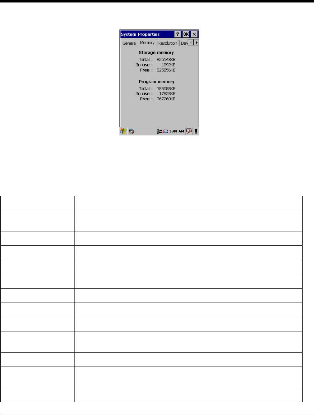
1. Tap Start > Settings > Control Panel > System > Memory tab.
Care and Cleaning of the Dolphin Terminal
When needed, clean the image or laser engine window and the LCD display with a clean, non-abrasive,
lint-free cloth. The terminal can be cleaned with a damp cloth.
Dolphin 6510 Technical Specifications
Operating System
Microsoft Windows CE 6.0
Development
Environment
Honeywell SDK for Windows® CE 6.0
Application Software
Honeywell Power Tools and Demos
Processor
TI Cortex-A8 1GHz
Memory
512MB RAM X 1 GB Flash
Expansion Memory
SD Card (full size) with capacities up to 32GByte. Recommended brand is ATP.
Display
3.5 in. transflective active matrix 65K color LCD with backlight, QVGA (240 x 320)
Backlight
LED
Engine
N560x 2D image engine with laser aimer or N4313 1D laser engine
Keypad
28-key shifted alpha numeric keypad or 52-key full alpha and numeric keypad with backlit
keys
Audio
Built-in microphone and speaker, stereo headset jack
Communication
Interface
High speed USB 2.0 (480Mbps) from cradle (or I/O cable); RS232 (115 Kbps) from cradle
Main Battery
Li-Ion battery 3.7V / 3300 mAh / 12.2 Wh (includes extended battery door)
3 - 17

Backup Battery
140mAh Li-ion Polymer.
Expected Hours of
Operation
3300mAh battery pack: 23 hours (N4313) / 22 hours (N560x)
(with scan every 2 seconds)
Battery life varies with application and use case.
Charging
5V/2A input through bottom access DC or USB/Serial
connector
Expected Charge Time
3300mAh - 5 1/2 hours for a fully depleted battery
Charging Peripherals
AC wall adapter and Charger (PSC11R-050)/Communication Cable
HomeBase–single-bay terminal charge/communicate
eBase–single-bay terminal charge/communicate (via Ethernet connection)
Quad Charger–four-slot battery pack charger (DSA-0421S-03 1)
WPAN (standard)
Bluetooth Class II (10 m) v2.1 Enhanced Data Rate (EDR) with on-board antenna. BQB
certified
WLAN (optional)
Quad Mode 802.11 a/b/g/n (11 Mbps/54 Mbps) with internal antenna
WLAN Security
WEP, 802.1x, LEAP, TKIP, MD5, EAP-TLS, EAP-TTLS, WPA-PSK, WPA v2.0, and PEAP
Operating Temperature
14° to122°F (-10° to 50°C)
Charging Temperature
32° to 104°F (0° to 40°C)
Storage Temperature
-4° to 158°F (-20° to 70°C)
Humidity
95% humidity, non-condensing
Construction
High impact resistant PC/ABS housings
Magnesium alloy internal chassis with component shock mounts
Drop
4 ft. (1.2m) multiple drops to concrete, all axis, across operating temperature range
Tumble
500 3.3 ft (1.0m) tumbles (1000 drops)
ESD
Air:
± 15k Vdc
Direct: ± 8k Vdc
Environmental Sealing
IP54 rating
Dimensions
200 mm long x 83 mm wide x 42 mm deep (7.87” x 3.27” x 1.65”) with extended battery
and hand strap.
Weight
354 g (12.5 oz) with standard battery and hand strap
380 g (13.4 oz) with extended battery and hand strap
Scanner / Decode
Capabilities
N560x 2D Imager with Adaptus Technology and Laser Aimer. Decodes all standard 1D,
2D, Postal, and OCR codes.
N4313 1D laser scanner. Decodes all standard 1D codes.
3 - 18

3 - 19
Regulatory and
Compliance Safety: UL60950-1, cUL 60950, IEC 60825-1:1993+A1:1997+A2:2001, NOM-019,
EN60950, CCC, PSE,
FCC Part 15, Sub part B, Sub Part C, ICES-003, RSS 210, EN 55022 (CISPR 22)
Class B, EN55024:1998, EN300 328, EN301 489-1, EN301 489-7, EN301 489-17, IEC
62209-2, SRRC, AIRB, ANATEL, AS/NZS4268, COFETEL
Using the Keypad
Overview
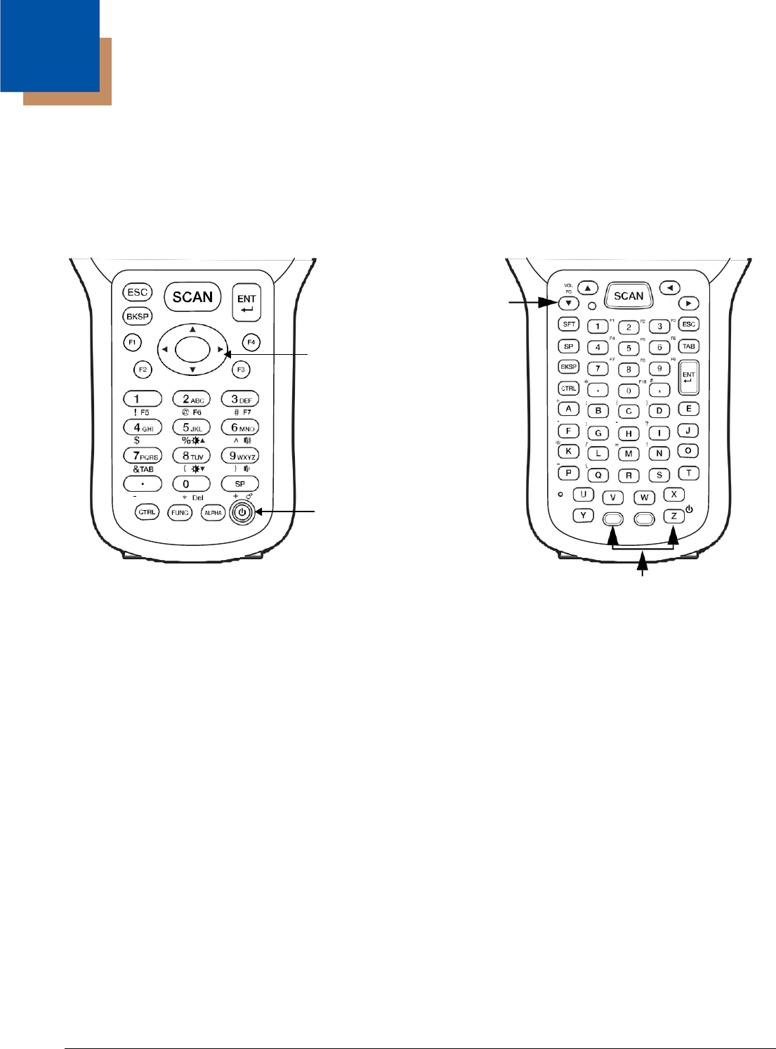
The 28-key and 52-key keypads are as follows:
28-key keypad (numeric) 52-key keypad (full alphanumeric)
Navigation keys
(arrow keys)
Navigation
keys
Power key
Power key combination
Navigation Keys
The navigation keys enable you to move the cursor up and down lines and from character to character.
4 - 1
4

Basic Keys
Name
Function
ALPHA (28-
key)
SFT (52-key)
Toggles the keyboard between alpha (upper and lowercase) and numeric
modes on the 28-key keypad. The “ABC”/”abc” indicator on the command
bar changes accordingly. Pressing SFT two times in rapid succession on a
52-key keypad toggles between upper and lowercase.
Backspace
(BKSP)
Backspace moves the cursor back one space.
If you are typing text, a character is deleted each time you press the
backspace key.
Control
(CTRL - 28-
key)
Blue key
(52-key)
Modifies the next key pressed to type specific characters (e.g., pressing
CTRL and a “2”, types an “@” sign on the 28-key keypad. Pressing the
Blue key and a “k” types an “@” sign on the 52-key keypad.
Escape
(ESC)
Cancels an action. For example, if you press the UP arrow on the
command bar and then press the ESC key, the pop-up window disappears.
Enter (ENT)
Performs the same function as the Enter key on a workstation.
Power
(Blue + Z -
52-key)
28 key: Power key suspends and resumes the terminal.
52 key: Blue + Z (Power) key suspends the terminal; just the Z (Power) key
resumes the terminal.
Scan
Activates the image engine to scan a bar code or take an image.
Space (SP)
Moves the cursor one space forward.
If you are typing text, it moves the text one space forward as well.
Alpha/Numeric Modes
28-key keypad: The keypad defaults to numeric mode. Use the ALPHA key to toggle between numeric and
alpha modes. Pressing the ALPHA key locks the keypad in numeric mode, alpha mode
(lowercase), or alpha mode (uppercase).
52-key keypad: The keypad is a full alpha and numeric keypad. Pressing the SFT key twice in rapid
succession toggles between upper and lowercase.
The command bar on the screen displays an icon that indicates the alpha/numeric status of the keypad.
Alpha Indicators on the Number Keys
Each number key displays the characters typed when you press that key in alpha mode.
4 - 2

Note that when typing in alpha mode on the 28-key Dolphin 6510, you must use the same multi-press
method you would use when typing letters on a phone keypad. Each key press types the next letter in the
sequence as displayed by the alpha indicator.
Function Key Combinations
On the 28-key keypad, hold down the Function key (FUNC) and then press a key with the blue text/icons
below it to perform specific functions.
28-key
Key Combination
Function
FUNC + 1
F5
FUNC + 2
F6
FUNC + 3
F7
FUNC + 4
Toggle the wireless radio on and off
FUNC + 5
Increase screen brightness
FUNC + 6
Increase volume
FUNC + 7
Tab
FUNC + 8
Decrease screen brightness
FUNC + 9
Decrease volume
FUNC + .
Start menu
FUNC + 0
Delete
FUNC + SP
Align the screen
(Press ESC to exit)
On the 52-key keypad, hold down the Red button and then press a key with the red text to the upper right
of it to perform specific functions.
52-key
Key Combination
Function
FUNC + 1
WordPad
FUNC + 2
Email
FUNC + 3
Windows Explorer
FUNC + 4
Internet Explorer
FUNC + 5
Pocket CMD
FUNC + 6
Control Panel
FUNC + 7
Transcriber
FUNC + 8
F8 - user programmable
4 - 3

52-key
Key Combination
Function
FUNC + 9
F9 - user programmable
FUNC + 10
F10 - user programmable
FUNC PG
Page up or down - used in conjunction
with Up and Down arrows
CTRL Key Combinations
On the 28-key keypad, hold down the Control key (CTRL) and then press a key with the red characters
below it to type the desired character.
28-key
Key Combination
Function
CTRL + 1
!
CTRL + 2
@
CTRL + 3
#
CTRL + 4
$
CTRL + 5
%
CTRL + 6
^
CTRL + 7
&
CTRL + 8
(
CTRL + 9
)
CTRL + .
- (minus)
CTRL + 0
*
CTRL + SP
+ (plus)
On the 52-key keypad, press the Blue button and then press a key with the blue text to the upper left of
it to type the desired character. You will need to press the Blue key before each special character.
52-key
Key Combination
Function
CTRL + A
+
CTRL + B
;
CTRL + C
(
CTRL + D
)
CTRL + F
-
4 - 4

52-key
Key Combination
Function
CTRL + G
:
CTRL + H
“
CTRL + I
?
CTRL + K
@
CTRL + L
/
CTRL + M
=
CTRL + N
!
CTRL + P
–
CTRL + Q
\
CTRL + U
Windows Explorer
CTRL + .
*
CTRL + ,
#
CTRL + VOL
Increase/decrease volume
Program Buttons
Buttons can be programmed to execute different functions using the Program Button program in the
Control Panel. The following buttons on the 28-key keypad are programmed for the listed function.
Key Combination
Function
F1
WordPad
F2
Email
F3
Windows Explorer
F4
Internet Explorer
4 - 5

Using the Image Engine
Overview
The Dolphin 6510 houses a compact image engine using Adaptus™ Imaging Technology that instantly
reads all popular 1D and 2D bar codes and supports omni-directional aiming and decoding. The image
engine can also capture digital images, such as signatures and pictures.
Available Image Engines
Dolphin 6510s are equipped with N560x Standard Range (N5603SR) image engines.
Depth of Field
N560x Standard Range (N5603SR)
7.5 mil
Linear
10 mil
PDF417
13 mil
UPC
20 mil
Data Matrix
20 mil
QR
32 mil
MaxiCode
Working
Range*:
(.019cm)
(.025cm)
(.033cm)
(.050cm)
(.050cm)
(.081cm)
Near
2.4 in.
(6.1cm)
1.7 in.
(4.3cm)
2.1 in.
(5.3cm)
2.9 in.
(
7.4cm)
2.0 in.
(5.1cm)
2.9 in.
(7.4cm)
Far
8.4 in.
(21.3cm)
10.5 in.
(26.7cm)
15.0 in.
(38.1cm)
14.2 in.
(36.1cm)
15.0 in.
(38.1cm)
15.3 in.
(38.9cm)
*Data characterized at 23°C and 0 lux ambient light.
5 - 1
5

Supported Bar Code Symbologies
Symbology Type
Symbology Name
1D Symbologies
Codabar
Interleaved 2 or 5
Code 3 of 9 Matrix 2 of 5
Code 11 Code 32 Pharmaceutical (PARAF)
Code 93 Straight 2 of 5 IATA
Code 128 Straight 2 of 5 Industrial
EAN with Add-On Telepen
EAN with Extended Coupon Code Trioptic Code
EAN-13
GS1-128
GS1 Databar UPC and UPC-A
2D Symbologies
Aztec Code
Composite
Data Matrix
GS1 Databar
Han Xin
MaxiCode
OCR
PDF417
QR Code
Composite Codes
Aztec Mesa
Codablock F
EAN·UCC
GS1 Databar-14
OCR
OCR-A
OCR-B
Postal Codes
Postnet and most international 4 state codes
Australian Post
British Post
Canadian Post
China Post
Japanese Post
KIX (Netherlands) Post
Korea Post
Planet Code
5 - 2

Activating the Engine
When a scanning application is open, press the Scan key to activate the image engine.
Using Demos
Dolphin Demos are software utilities loaded on all Dolphin terminals that demonstrate the advanced
features of the terminal. There are two Demos that feature the image engine: Image Demo and Scan
Demo.
To access these demos, tap Start > Programs > Demos.
• Select Scan Demo to verify decoding, or
• Select Image Demo to verify imaging (not available on device using the N4313 laser engine).
For more information about Demos, refer to the Dolphin Demos User’s Guide, which is available for
download from www.honeywellaidc.com.
Decoding
The Dolphin terminal supports two types of image decoding: full-area imaging and Advanced Linear
Decoding (ALD).
Full-area Imaging
Full-area imaging means that the Dolphin terminal supports omni-directional aiming, meaning
that a positive read can be obtained from many positions. For details, see Omni-Directional
Scanning Positions on page 5-4.
ALD
ALD provides fast reading of linear (1D) and stacked linear bar codes (PDF417). For the best
read, the aiming pattern should be centered horizontally across the bar code. When ALD is
enabled, the reader does not read matrix or postal codes.
To Decode a Bar Code
1. Tap Start > Programs > Demos > Scan Demo.
2. Position the Dolphin terminal over one of the sample bar codes on page 5-4.
A range of 4-10 inches (10-25 cm) from the bar code is recommended.
3. Project the aiming brackets by pressing and holding the Scan key. The Scan LED lights red.
4. Center the aimer crosshair over the bar code. The aiming beam should be oriented in line with the
bar code to achieve optimal decoding; Omni-Directional Scanning Positions, page 5-4
5. When the bar code is successfully decoded, the decode LED lights green and the terminal beeps.
5 - 3
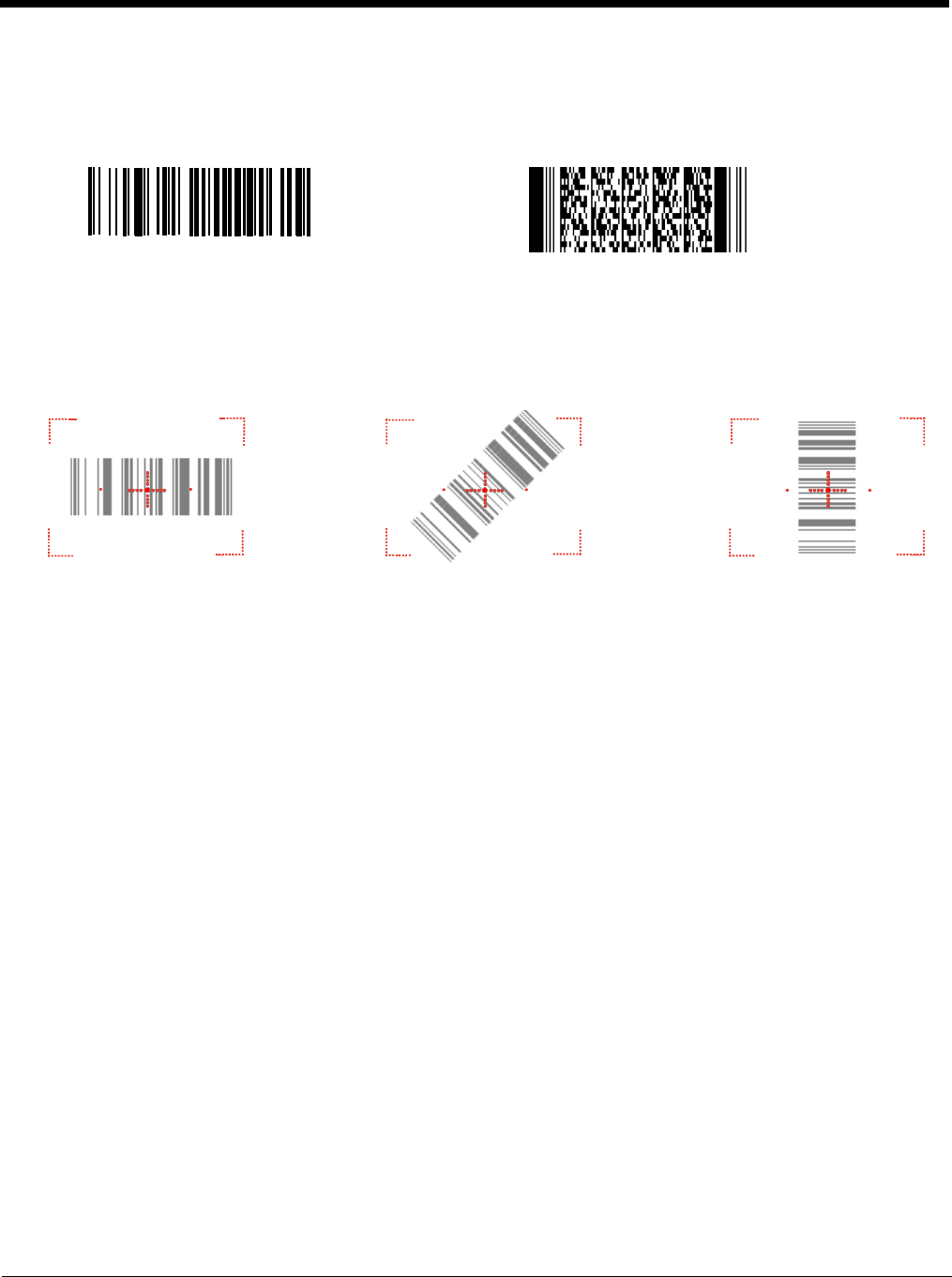
Sample Bar Codes
You can use the following bar codes to verify decoding:
Sample 128 Sample PDF417
Code 128 PDF417 Test Message
Omni-Directional Scanning Positions
The high-vis aiming pattern frames the bar code to provide you with the best scanning performance.
Note: To achieve the best read, the aiming beam should be centered horizontally across the bar code.
The aiming pattern is smaller when the terminal is held closer to the code and larger when the terminal is
held farther from the code. Symbologies with smaller bars or elements (mil size) should be read closer to
the unit whereas larger bars or elements (mil size) should be read farther from the unit.
5 - 4

Capturing Images
The image-capture process is an intuitive, split-second operation for experienced users. By following
basic guidelines, however, new users can easily develop their own technique and, with practice, quickly
learn to adapt to different application environments.
Image Preview
When the imaging process is initiated, the touch screen displays a preview of the object. This
is a live video image of what the imager is currently viewing and has a slightly degraded
appearance compared to the captured image. This is normal; the captured image has a higher
resolution.
File Formats
The Dolphin terminal is capable of saving images in a number of industry-standard file formats
(BMP, JPG and PNG). The default file format for images is a grayscale BMP.
File Size
Digital images have a maximum image size of 640 x 480 pixels and may have up to a 256
grayscale image definition. The image quality and related file size are determined by the data
compression method used by the software application used to take the image. The average
size of the image file is approximately 4-8K. However, the size of the image depends on image
content; the more complex the content, the larger the file size.
Taking an Image
1. Tap Start > Programs > Demos > Image Demo.
2. Point the Dolphin terminal at the object.
3. Press the Scan key to activate the engine. The touch screen displays a preview of the object.
4. Adjust the terminal’s position until the preview on the screen is as you want it to appear in the image.
5. Hold the terminal still and release the Scan key.
The touch screen flashes, and the captured image appears on the screen.
6. By default, the image is saved to the My Documents folder in My Device.
To save the image to another location, tap File > Save As.
High-Vis Aiming Pattern
If your Dolphin terminal is configured with the N5603SR imager, you can enable the aiming pattern for
imaging in the Image Demo application.
1. Tap Start > Programs > Demos > Imaging Demo > Setup menu > Aimer.
2. The aiming pattern is now enabled for imaging.
Uploading Images
Image files can be transmitted to a host workstation via
• Microsoft ActiveSync and a Dolphin communication peripheral
• Wireless radio: 802.11b/g and/or Bluetooth
5 - 5
6

Using the Laser Engine
Overview
The Dolphin 6510 (N4313-TTL laser version) contains a laser diode that emits a beam toward an
oscillating mirror that scans through the code and the reflected light is bounced off of two mirrors back to
the collector. The 6510 Laser reads all popular 1D bar codes.
Available Laser Engines
The Dolphin 6510 can be equipped with an N4313-TTL laser engine (depending on the configuration
purchased).
Depth of Field - N4313-TTL
5.2 mil
7.5 mil
10.4 mil
13.0 mil
19.5 mil
Working
Range*:
(25mm)
(114mm)
(160mm)
(204mm)
(225mm)
Near
2.75 in.
(70mm)
2.25 in.
(57mm)
2.00 in.
(50mm)
2.00in.
(50mm)
2.95 in.
(75mm)
Far
3.75 in.
(95mm)
6.75 in.
(171mm)
8.25 in.
(210mm)
10.00 in.
(254mm)
11.81 in.
(300mm)
*Data characterized at 25°C (77°F) under typical indoor lighting.
Supported Bar Code Symbologies
Symbology Type
Symbology Name
1D Symbologies
China Post ISBT 128
Codabar
Korea Post
Code 11 Matrix 2 of 5
Code 32 Pharmaceutical (PARAF) MSI
Code 39 PosiCode
Code 93/93i Straight 2 of 5 IATA
EAN-8
Straight 2 of 5 Industrial
EAN-13
Telepen
GS1-128
Trioptic Code
GS1 Databar UPC-A, UPC-E0, UPC-E1
Interleaved 2 of 5
6 - 1
6

Preliminary 2013-10-29
Activating the Engine
When a scanning application is open, press the Scan key to activate the laser engine.
Using Demos
Dolphin Demos are software utilities loaded on Dolphin terminals that demonstrate the advanced features
of the terminal.
Decoding a Bar Code
1. Tap > Demos > Scan Demo.
2. Position the Dolphin terminal over one of the sample bar code below.
A range of 4-10 inches (10-25 cm) from the bar code is recommended.
3. Project the aiming beam by pressing and holding the Scan key. The Scan LED lights red.
4. Center the aimer beam horizontally over the bar code and highlight all of the vertical bars of the bar
code. The aiming pattern is smaller when the terminal is held closer to the code and larger when the
terminal is held farther from the code. Symbologies with smaller bars or elements (mil size) should
be read closer to the unit whereas larger bars or elements (mil size) should be read farther from the
unit.
5. When the bar code is successfully decoded, the decode LED lights green and the terminal beeps.
Sample Bar Code
You can use the following bar code to verify decoding:
Sample 128
Scanning Positions
The aiming beam must be aimed across the entire bar code to provide the best scanning performance.
6 - 2

System Settings
Communication Options
Dolphin terminals offer several communication options including Microsoft ActiveSync and wireless
radios.
I/O Connector (Wired Communication)
The mechanical connector on the bottom panel (see DC Power Jack on page 3-11) connects
the terminal to various Dolphin communication peripherals that connect to a host workstation
via USB (1.1 or higher), thus enabling ActiveSync communication.
For more information, see ActiveSync Communication on page 7-3.
Wireless Radios (Wireless Communication)
Dolphin 6510s can be equipped with 802.11b/g and Bluetooth radios or just a Bluetooth radio.
For more information, see Wireless Radios on page 7-6.
Installing Additional Software
Dolphin terminals ship with the operating system, radio drivers, and custom Honeywell software already
installed. These are the default programs that install when your terminal first boots up. You can install
additional software programs on the terminal provided that the following parameters are met:
• the software program was created for a Windows CE device.
• the terminal has enough memory to store and run the program.
• the program has an EXE, CAB, or DLL extension.
When selecting programs, verify that the program and version of the program are designed for the
Windows CE 6.0 and the terminal’s processor. You can verify your processor by tapping Start > Settings
> Control Panel > System > General tab. Make a note of the information in the Processor field.
To install additional software, you can use the communication options described in this chapter.
• Adding Programs via ActiveSync, page 7-5.
• Adding Programs from the Internet, page 7-7.
7 - 1
7
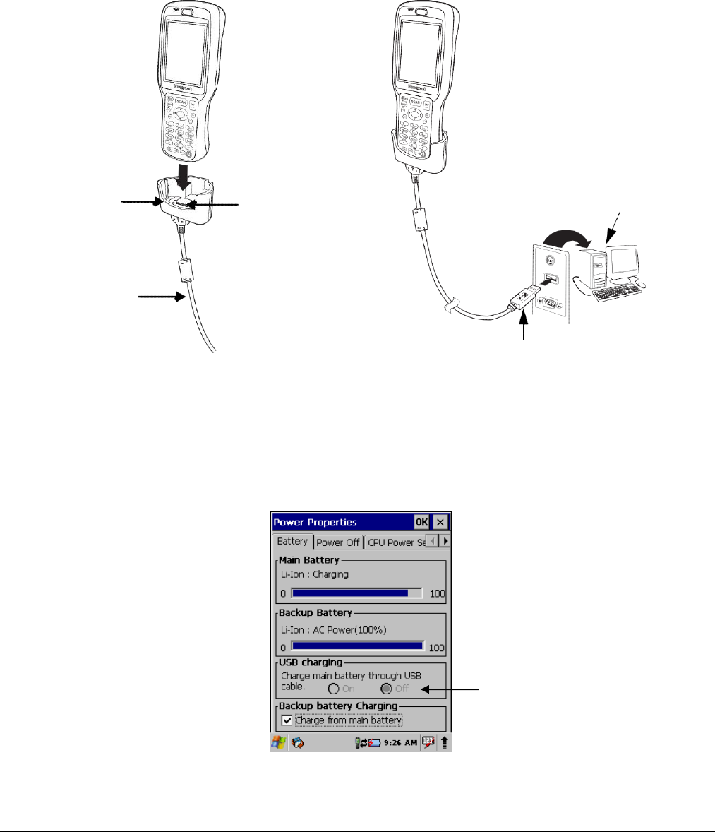
Connecting the USB Charging/Communication Cable for the Dolphin 6510
Slide the USB cable unit onto the bottom of the terminal lining up the terminal’s I/O connector to the cable
unit’s connector to facilitate USB communication between the Dolphin terminal and the host workstation.
Hole for
Power Cable
Connector
Host
Workstation
USB Cable
USB Connector
Charging Terminal with USB Cable
Not only can you communicate between the terminal and the host using the Dolphin Charging/
Communication cable, but you can also trickle charge the terminal. To charge the main battery using the
USB cable, select Start > Settings > Control Panel >Battery > USB charging. The default setting is
On.
7 - 2

ActiveSync Communication
To synchronize, ActiveSync 4.1 or higher must be installed and configured for the appropriate
communication type on the host workstation and the Dolphin terminal. Dolphin terminals ship with
ActiveSync already installed. Therefore, if ActiveSync is already installed on the host workstation, you just
need to connect the Dolphin terminal to the host workstation (via Dolphin peripheral) to initiate
communication.
Note: You can download the most current version of ActiveSync from www.microsoft.com.
When communicating via ActiveSync, your terminal is designed to be connected to the host workstation with
a Honeywell communication peripheral. We recommend use of Honeywell peripherals, power cables, and
power adapters. Use of any non-Honeywell peripherals, cables, or power adapters may cause damage not
covered by the warranty.
Communication Type
The Dolphin 6510 supports the following type of communication via ActiveSync through its DC Power
Jack (see page 3-11) on the bottom panel:
USB
The USB cable and hardware peripherals allow the Dolphin terminal to communicate with
a workstation through a USB port or to a network through a USB hub. The Dolphin terminal
supports full-speed USB communication (USB 1.1); maximum data transfer rate is 12
Mbps. The Dolphin terminal defaults to USB communication out of the box.
Hardware Requirements for Setup
• Dolphin communication peripheral
• Dolphin power cable
• USB Cable (for USB communication)
• ActiveSync v4.1 or higher installed on the host workstation
• Windows 98 Second Edition, Windows Me, Windows 2000, Windows NT (4.0 SP6 or higher) or
Windows XP computer.
Software Requirements for Communication
To sync successfully, ActiveSync must be configured for the same communication type on both the host
workstation and the Dolphin terminal. ActiveSync must be setup on your workstation before you initiate
synchronization from the terminal for the first time.
Setting Up the Host Workstation
Verify that ActiveSync is configured to use the appropriate communication type by clicking File >
Connection Settings.
For USB communication, check Allow USB connections.
7 - 3
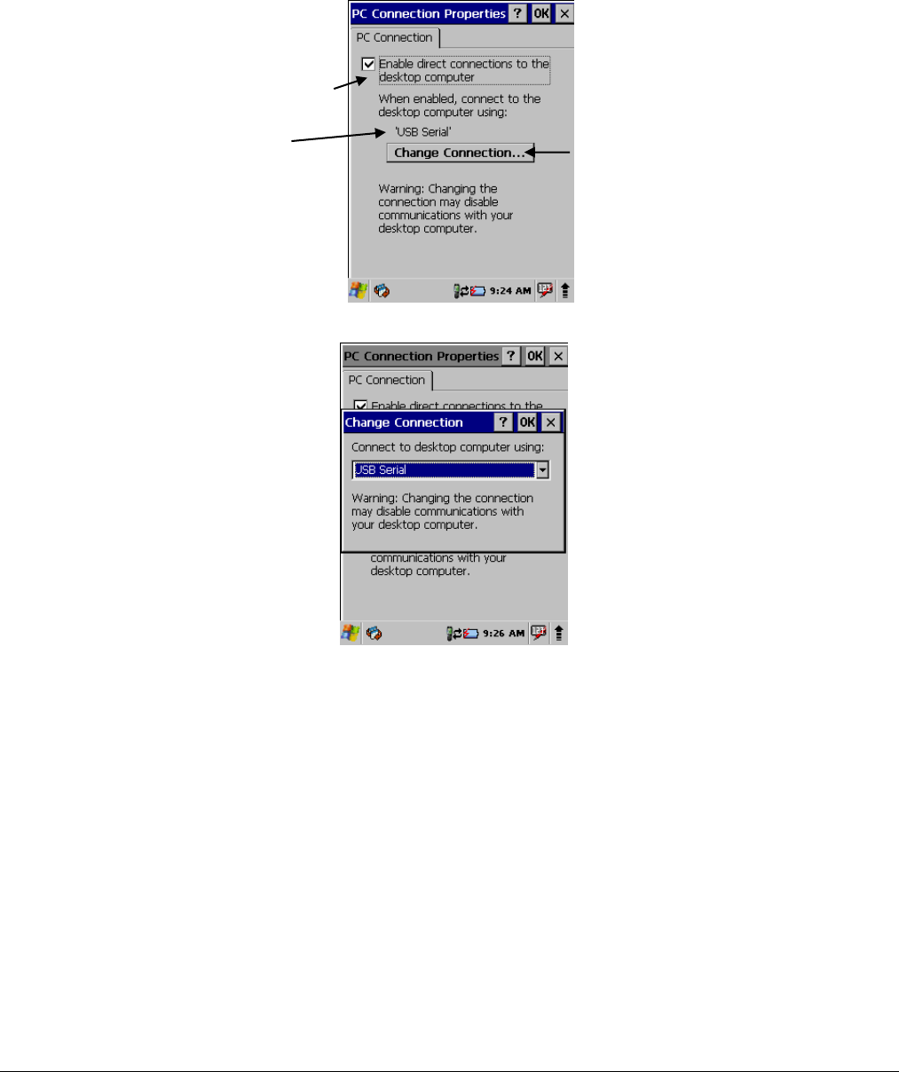
Setting Up the Dolphin Terminal
The Dolphin terminal defaults to USB communication out of the box. To verify and/or change the default
setting, tap Start > Settings > Control Panel > PC Connection.
Must be checked to connect to a workstation
Displays the current connection setting Tap to change the connection settings
Tap Change Connection to change the current settings.
Connection Options Select this option to …
‘USB
Establish a USB connection.
Communicating with the Dolphin Terminal
After setting up both the workstation and the terminal, ActiveSync connection should be automatic.
1. Connect the Dolphin terminal to a communication peripheral, such as the Dolphin HomeBase.
2. The Dolphin terminal automatically opens ActiveSync to establish a connection.
Synchronizing with the Host Workstation
After setup, synchronization begins automatically whenever the terminal’s mechanical connector
connects to a Dolphin peripheral that is connected to a host workstation with ActiveSync installed.
7 - 4
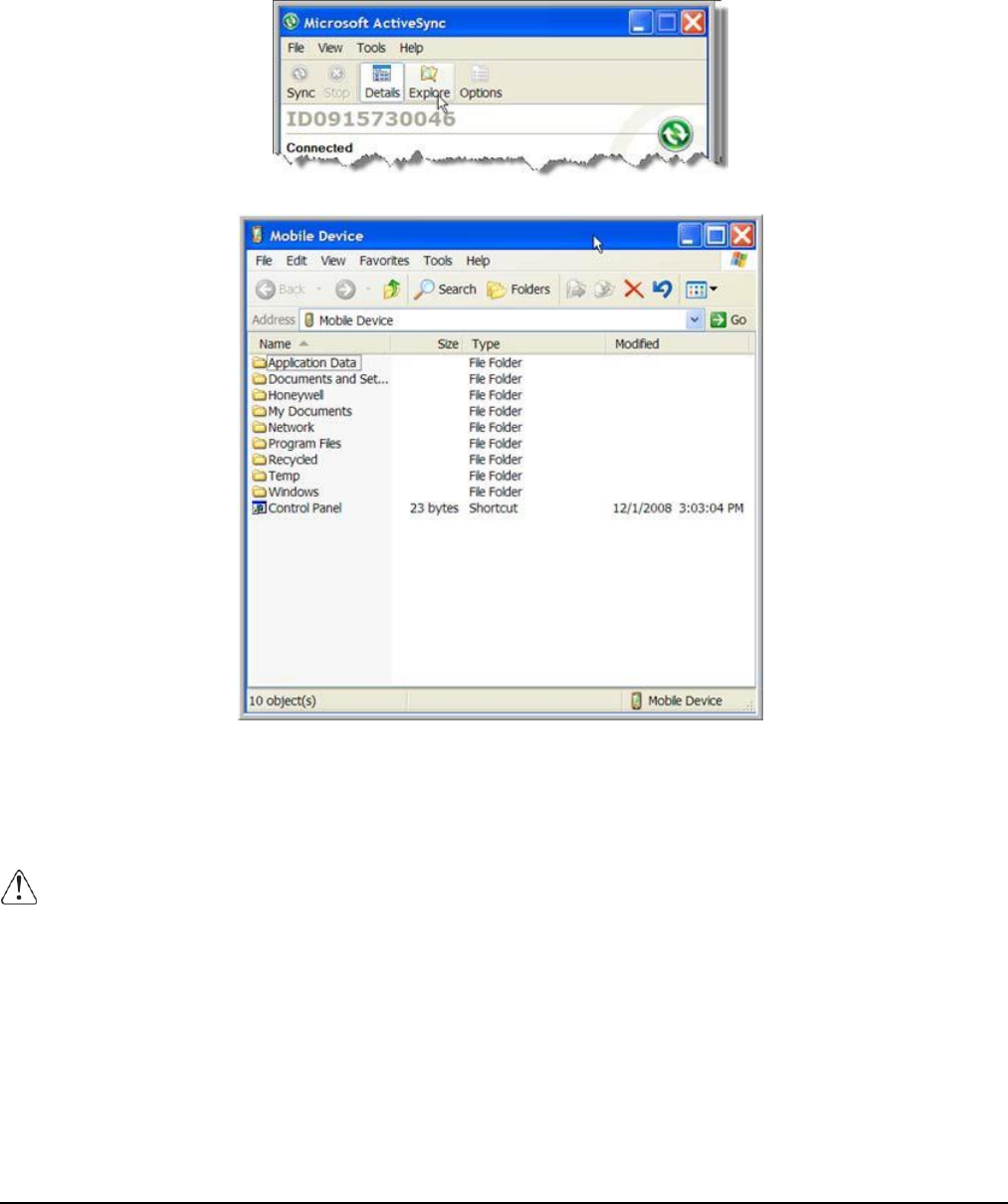
Exploring the Terminal from the Workstation
When the terminal and desktop computer are connected, open the main ActiveSync window (on the
desktop), and click Explore.
The Mobile Device folder opens in Windows Explorer.
The Dolphin terminal is now treated as a mass storage device, and transferring files is as simple as
dragging and dropping or copying and pasting as you would for moving files between folders on your hard
drive.
Adding Programs via ActiveSync
When selecting programs, verify that the program and version of the program are designed for the Windows CE 6.0 and
the terminal’s processor. You can verify your processor by tapping Start > Settings > Control Panel > System > General
tab. Make a note of the information in the Processor field.
Generally, software for Windows CE devices must be installed to the host workstation first, then
transferred to the Dolphin terminal.
1. Download the program to the workstation from either the Internet or the install CD. You may see a
single *.exe or setup.exe file, a *.cab file, or *.dll. (There may also be several versions of files for dif-
ferent device types and processors.)
2. Read any installation instructions, Read Me files, or documentation that comes with the program.
Many programs provide special installation instructions.
3. Connect the terminal to the workstation via a Dolphin communication peripheral.
7 - 5

If the File is an Installer
An installer program is one that installs to the workstation and the terminal simultaneously; one process
installs to both devices.
1. On the workstation, double-click the *.exe or *.setup.exe file. The installation wizard begins.
2. Follow the directions on the workstation screen.
The installation process includes transferring the software to the terminal via ActiveSync.
If the File is Not an Installer
Some programs cannot be installed on workstations because they are designed exclusively for Windows
CE devices. In these cases, the appropriate files must be stored on the host workstation and transferred
to the terminal via ActiveSync Explore.
Note: You know that the program is not an installer because an error message stating that the program is valid but
designed for a different type of computer appears when you try to install the program on the workstation.
1. If you cannot find any installation instructions for the program in the Read Me file or documentation,
open ActiveSync on the workstation and click Explore.
2. On the workstation, navigate to the workstation folder containing the program file(s) and copy them
to the Program Files folder on the terminal.
If you want the program to persist through hard resets, paste the program to the Autoinstall folder
(\Honeywell\AutoInstall).
3. On the terminal Desktop, tap My Device and, in Windows Explorer, navigate to the folder where the
program is located.
4. Double tap on the program file to install it.
If you copied the file to the Autoinstall folder, you can choose to install the program by performing a
hard reset. The program installs as part of initialization.
5. After installation is complete, access the program by tapping Start > Programs, and the program
appears on the Programs screen. Tap the icon to open the program.
Wireless Radios
There are two radio options: 802.11b/g and Bluetooth.
1. 802.11b/g (WPAN/WLAN configuration): see WLAN (802.11b/g Radio), below.
2. Bluetooth (WPAN configuration): see Bluetooth Handler on page 8-1.
Connecting the Terminal to a Wireless Network
You connect the terminal to a wireless network through the on-board radio (802.11b/g and/or Bluetooth).
Each radio has its own configuration program and requires specific information about the wireless
network to connect. Successful connection depends on your network infrastructure about which you will
need specific information from your network administrator.
WLAN (802.11b/g Radio)
Dolphin 6510s can have a 2.4 GHz 802.11b/g WLAN (Wireless Local Area Network) radio that uses Direct
Sequence Spread Spectrum (DSSS) technology. The radio is interoperable with other 802.11b/g, Wi-Fi-
compliant products including access points (APs), workstations via PC card adapters, and other wireless
portable devices.
7 - 6

By default, the 802.11b/g radio is powered off (i.e., disabled) “out of the box.” To power it on (i.e., enable),
press the vertical arrow (bottom, right corner of screen) and select Turn Wireless LAN On. The enable/
disable state of the radio will survive subsequent soft and hard resets. The next step is to configure the
connection parameters of the radio to connect to a wireless network.
Configuring the WLAN Radio
The WLAN radio is configured in the Honeywell WLAN Security Supplicant, which you access by double
tapping the program icon in the command bar.
For complete configuration instructions, download the Honeywell Secure Wireless (SWC) Client User’s
Guide from www.honeywellaidc.com. A link to this guide appears on the Dolphin 6510 product page.
Adding Programs from the Internet
When you have established a network connection (whether via Wireless LAN, Bluetooth, or ActiveSync,
you can access the Internet and download additional software programs.
When selecting programs, verify that the program and version of the program are designed for Windows CE6.0 and
the terminal’s processor. You can verify your processor by tapping Start > Settings > Control Panel > System >
General tab. Make a note of the information in the Processor field.
1. Open Internet Explorer and navigate to the program’s location. You may see a single *.exe or
setup.exe file, or several versions of files for different device types and processors.
2. Select the program version that matches your Dolphin terminal and processor.
3. Read any installation instructions, Read Me files, or documentation that comes with the program.
Many programs provide special installation instructions.
4. Download the program to the terminal directly from the Internet.
You would normally store the program in the \Program Files folder unless another location is
required by the program.
5. On the terminal, double tap the installer file; e.g., the *.exe file.
6. The installation wizard for the program begins.
7. Follow the directions on the screen to complete installation.
7 - 7

Bluetooth Handler
Bluetooth wireless technology is a short-range communications technology to connect
portable and/or fixed devices while maintaining high levels of security.
Enabling the Bluetooth Radio
1. Select the UP arrow in the lower, right portion of the display.
2. Tap Turn Bluetooth On.
The Bluetooth icon appears in the task bar.
Connecting to Other Devices
Before connecting to another device, make sure that the Bluetooth connection on the other
device is enabled.
1. Double tap on the Bluetooth icon in the task bar.
The Bluetooth Handler appears on the screen.
2. Tap Scan Device.
The available services of all devices / profiles in range display in the Bluetooth Handler.
Pairing Bluetooth Devices
Connecting Bluetooth devices usually requires that they be paired; the same passkey must be
entered for each device. If you want to connect the Dolphin 6510 to a device without any input
method (e.g., printers, headsets), refer to the user documentation that accompanied the
device for pairing information.
1. Tap on the desired device / profile in the Bluetooth Handler.
2. Select Trusted from the drop down
menu. Once asked if you need to
authenticate the device,
3. Tap on the Yes button.
4. Enter 4 random digits and tap Yes.
5. Enter the same digits on the other device when prompted.
6. After pairing, double tap on the selected device / profile and select Active.
Setting Up a Bluetooth Printer
1. Make sure that the Bluetooth printer is on and activated.
2. If not done so already, turn Bluetooth On (by selecting the vertical arrow on the Command
Bar).
3. Tap Serial tab.
4. Tap Scan Device, which runs a Bluetooth Inquiry, then SDP Query.
5. If you see your Bluetooth printer device displayed, you can tap Cancel to stop the search.
8 - 1
8
OR
Wait until all Bluetooth devices in range have been scanned. Then the Scan Dialog window appears.
6. Scroll through the list until your Bluetooth printer device is found. You may single tap any device
in the list to display its MAC address.
7. Highlight the Bluetooth printer device and tap the Select button.
8. When the COM port selection appears, select COM7 and tap OK.
9. If successful, the COM port and MAC address of the device appears under the list of
Registered Bluetooth Virtual COM ports.
10. Tap OK to exit the Bluetooth Handler.
11. One of the ways to test the connection to the printer is to follow the steps below:
a. Select Start > Programs > Demos > Print Demo.
b. Tap Zebra (BT) Barcodes Print.
c. If successful, the barcode prints.
Setting Up a Connection to a Mobile Phone
You can use a GSM mobile phone as a modem to connect to the Internet using GPRS (General
Packet Radio Service) data connection.
Prior to connecting the Dolphin 6510 to a mobile phone, contact your mobile phone service provider about
the GPRS configuration, coverage, and fees. Also consult the user documentation for your mobile phone
to determine if your phone supports GPRS data transfer and if it has an available Bluetooth connection.
If your phone supports 3G data transfer, you should be able to connect the Dolphin 6510 to your phone.
1. Determine if your phone is configured and connected to GPRS.
2. Activate your mobile phone’s Bluetooth feature.
3. Select Start > Settings > Network and Dial-up Connections.
4. Double tap on Make New Connections.
5. Choose Dial-up Connection and select Next.
6. Select Bluetooth.
7. Select and activate the data modem service for your phone (refer to Pairing Bluetooth Devices
(page 8-1) and press OK.
8. Select the data modem service from step 7 from the Select a Modem: drop down menu.
9. Enter a dial-up phone number. (Contact you mobile network services provider for additional
information about connecting the Internet using your mobile phone.)
10. Tap Finish.

9 -1
!
Dolphin HomeBase/eBase Device
Overview
Note: The information in this chapter applies to both the Dolphin HomeBase and Dolphin eBase devices unless
otherwise indicated.
As the hub of your Dolphin 6500 system, the Dolphin HomeBase charging and communication cradle
supports full-speed USB 1.1 and RS-232 communication with a workstation. The Dolphin eBase is
identical to the Dolphin HomeBase except it supports Ethernet communication as well as USB 1.1, and
RS-232.
Communication
The base can communicate via USB or serial RS-232 (or Ethernet for the eBase). Data transmission for
USB is up to 12 Mbps. Data transmission for serial RS-232 is up to 115 Kbps.
These bases cannot be physically connected to each other–sometimes referred to as “daisy-chaining”–
but can be networked together via serial or USB hubs.
Battery Charging
The base completes a full charge of a fully depleted main battery pack in an average of 5 1/2 hours. It
takes less time if the battery has some charge.
In addition to charging, the base powers the terminal’s intelligent battery charging system, which protects
the battery from being damaged by overcharging. The terminal senses when a battery pack is fully
charged and automatically turns off the charger. If the battery voltage drops below the charge threshold,
the charger turns on again to maintain the battery at full capacity. As a result, Dolphin terminals may be
stored in the base indefinitely without damage to the terminals, battery packs, or peripherals. For
prolonged storage, see Storage Guidelines on page 3-14. The base can also charge a second battery
while the terminal is positioned in the base. See Charging a Spare Battery on page 10-6.
Power Supply
The power cable that ships with each terminal also powers the base.
We recommend use of Honeywell peripherals, power cables, and power adapters. Use of any non-Honeywell
peripherals, cables, or power adapters may cause damage not covered by the warranty.
We recommend use of Honeywell Li-Ion battery packs. Use of any non-Honeywell battery may result in
damage not covered by the warranty.
Ensure all components are dry prior to mating terminals/batteries with peripheral devices. Mating wet
components may cause damage not covered by the warranty.
9
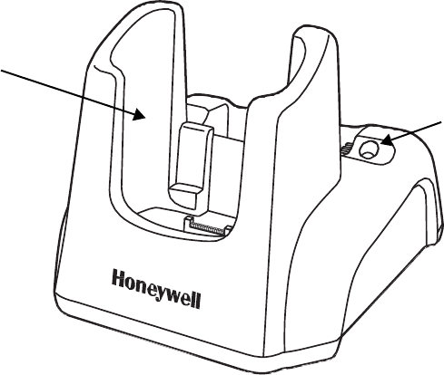
9-2
Front Panel
Terminal Well
Charging LED
Terminal Well
Place the Dolphin terminal in the terminal well to communicate with a host device, power the
terminal, and charge the terminal’s battery. Make sure that the device is securely seated.
Rubber Feet
The bottom panel has four rubber feet to stabilize the unit on a flat surface. You can set the
base on a dry, stable surface, such as a desktop or workbench near an electrical outlet.
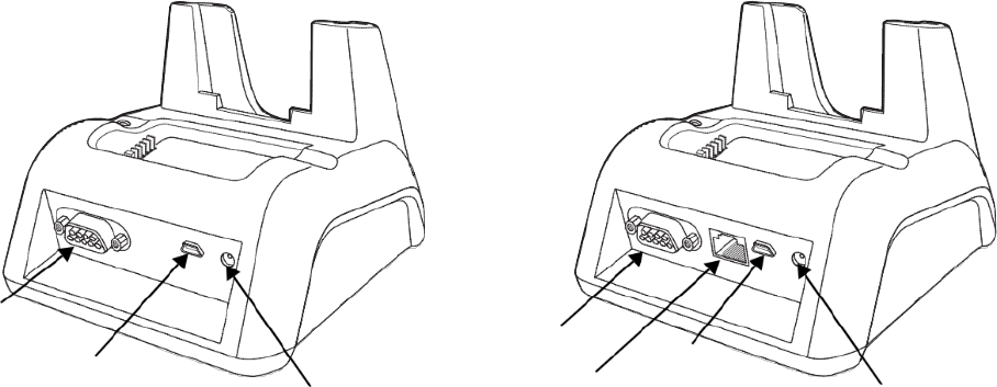
9 -1
Back Panel
HomeBase
eBase
Serial Port
USB Port
DC Power Jack
Serial Port
Ethernet Port
USB Port
DC Power Jack
DC Power Jack
Connect the power cable to this power jack; see Powering the Dolphin HomeBase Device on
page 10-4.
USB Port
The USB port is full-speed (v1.1). Using the USB cable, you can connect the base to a USB-
compliant device to facilitate USB communication to and from the terminal. USB
communication occurs through Microsoft ActiveSync (v.4.1 or higher). For more information
about ActiveSync setup, see Connecting and Synchronizing the Terminal and Workstation on
page 8-9.
Serial Port
The serial port supports serial communication between the terminal and another device. Note
that the connector is a DB9 Male connector, requiring a female connector on the serial cable.
The following four signals are supported:
•
Transmitted Data
•
Received Data
•
Request to Send
•
Clear to Send
Note: ActiveSync is not supported over the serial port.
Ethernet Port (eBase only)
Using an Ethernet cable, you can connect the eBase to an Ethernet-compliant device to facilitate Ethernet
communication to and from the terminal. This equipment is for indoor use only. The communication
wiring is limited to the inside of a building.
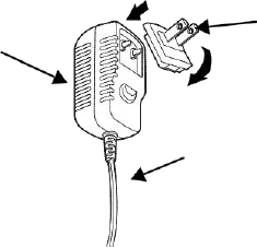
9 -1
Powering the Dolphin HomeBase Device
The terminal requires 5 volts DC input for communication and battery charging; the power adapter on the
power cable converts the voltage from the power source to 5 volts DC. Only power adapter cables from
Honeywell convert the voltage appropriately.
The same power cable that ships with each terminal can be used to power the base. This cable contains
a plug adapter for each geography (US, UK, EU, etc.).
Plug Adapter
Power Adapter
Power Cable
1. Attach the appropriate plug adapter to the power adapter.
2. Plug the power cable into the power source.
3. Plug the connector into the DC power jack on the back panel. The base is now powered.
When a terminal is properly seated, the base powers the terminal, charges the terminal’s main battery
pack, and launches ActiveSync (see Connecting and Synchronizing the Terminal and Workstation on
page 8-9).
Honeywell recommends that you leave the base connected to its power source at all times, so that it is
always ready to use.
eBase Clamp-on Ferrite Core Installation
We recommend that you install the clamp-on ferrite core included with your Dolphin® eBase on your
Ethernet cable. Installation of the ferrite is required to meet the declared FCC emission levels.
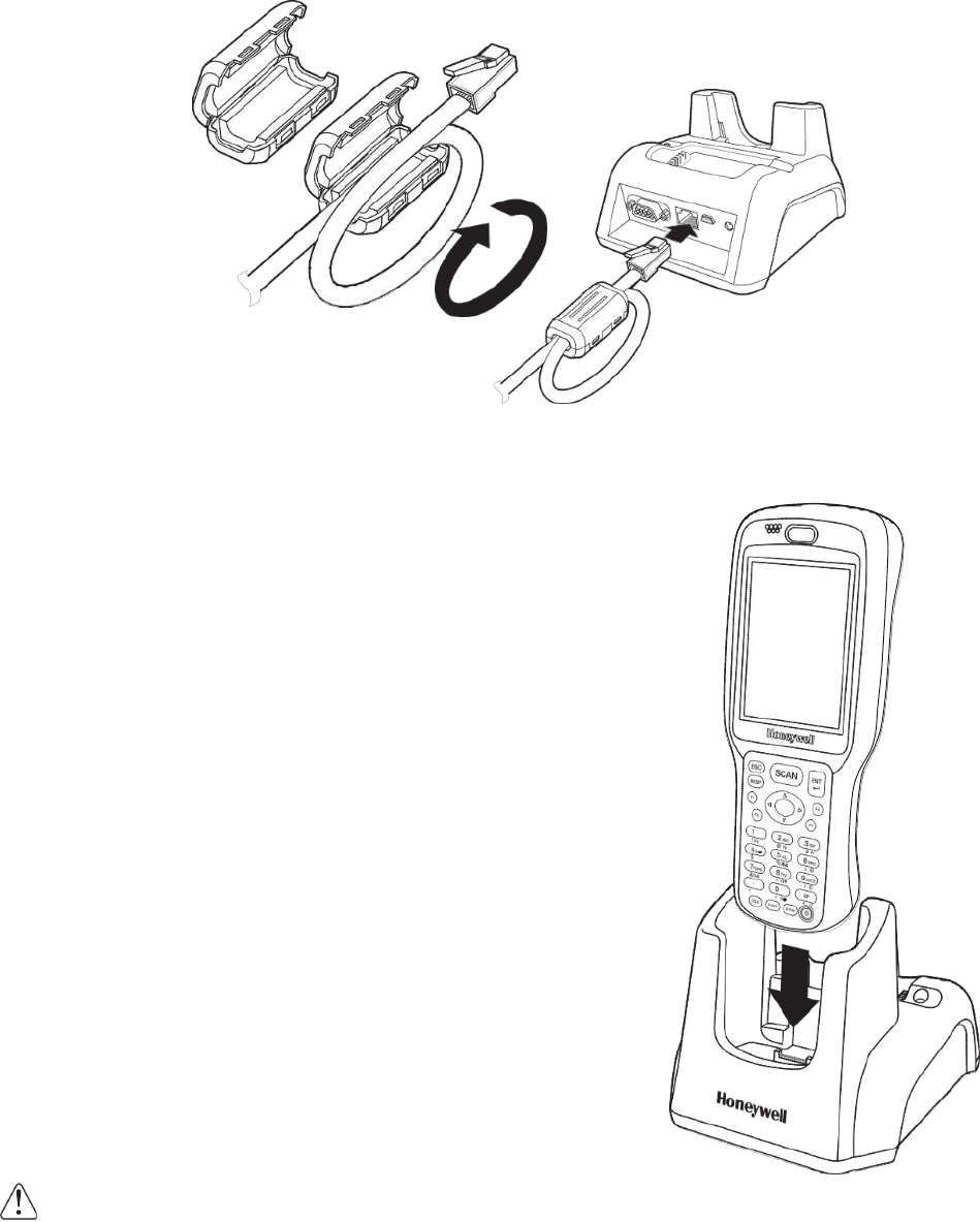
9 -1
!
The following illustration shows how to install the ferrite on the cable. It should be placed approximately
1.57 inches (40mm) from the RJ45 plug. The cable should be looped around the core, as shown.
Charging the Main Battery
The base powers the terminal and fully charges its main
battery pack in an average of 5 1/2 hours for a fully depleted
battery. It takes less time if the battery has some charge.
As battery packs charge, the charging circuitry follows the two-
step charging process (CC-CV) that is recommended for Li-Ion
batteries. The process monitors changes in temperature,
current, and voltage.
Inserting a Terminal
1. Install the battery pack in the terminal; see Install the
Main Battery on page 2-1.
2. Power the base; see Powering the Dolphin HomeBase
Device on page 10-4.
3. Slide the terminal into the terminal well making certain
that the terminal is seated properly.
4. The battery pack begins charging.
Ensure all components are dry prior to mating terminals/
batteries with peripheral devices. Mating wet components may cause damage not covered by the warranty.
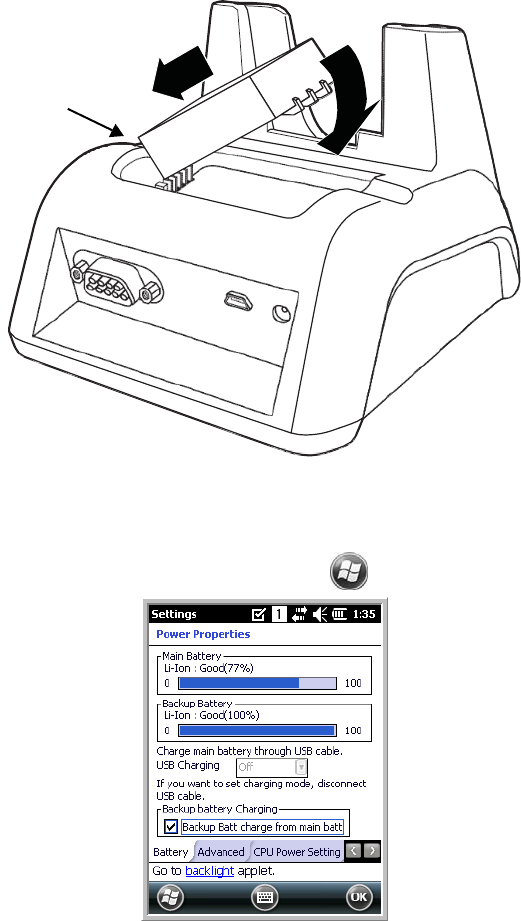
9 -1
Charging a Spare Battery
The base can also charge a second battery while the terminal is positioned in the base. The second
battery can be inserted in the battery charging well in back of the terminal connection. Place the battery
in the well with the label facing up and toward the back of the unit. Angle the battery as shown. Once the
connectors engage, the LED lights. If the LED is red, the unit is charging; if it is green, the charge is
complete.
Checking Battery Power
To check battery power while the terminal is operating, tap > Settings > Power.
Charging LED

9 -1
Technical Specifications
Structural
Dimensions
5.3 in. high X 4.5 in. wide X 3.1 in. deep (13.5 cm. X 11.4 cm. X 7.9 cm.)
Weight
Dolphin HomeBase - 11.0 oz. (313g)
Dolphin eBase - 11.3 oz (320g)
Material
Polycarbonate
Color
Black
Environmental
Operating Temperature
14° to 122°F (-10° to +50°C)
Storage Temperature
-4° to 158°F (-20° to +70°C)
Charging Temperature
32° to 104°F (0° to 40°C)
Electrical Static Discharge
Air
:
± 15k Vdc
Direct: ± 8k Vdc
Humidity
90% relative humidity (non-condensing)
Power Supply
Input (Universal)
(from the power source)
100–240 Volts, 0.3 A
50–60Hz
Included with Dolphin terminal
Output (to the base)
5 Volts DC, 2.0 A
Charging
Standard Charge
3300mAh - 5 1/2 hours for a fully depleted battery
Max Charging Current
1.8A Max
Standby Current
<100mA
Status LED
Green: charged
Red: charging
Communication
Interface
USB Mini-B Male connector supports data transmission of up to12 Mbps
OR
Standard DB9 serial connector supports data transmission up to 115 Kbps
Agency Approvals
Power Supply:
UL listed
TUV licensed
Power Supply compliant to FCC part 15, Class B
Charging:
CE Marking (EMC)
CISPR Pub 22
Fire Retardant:
UL 94-VO

9 -1
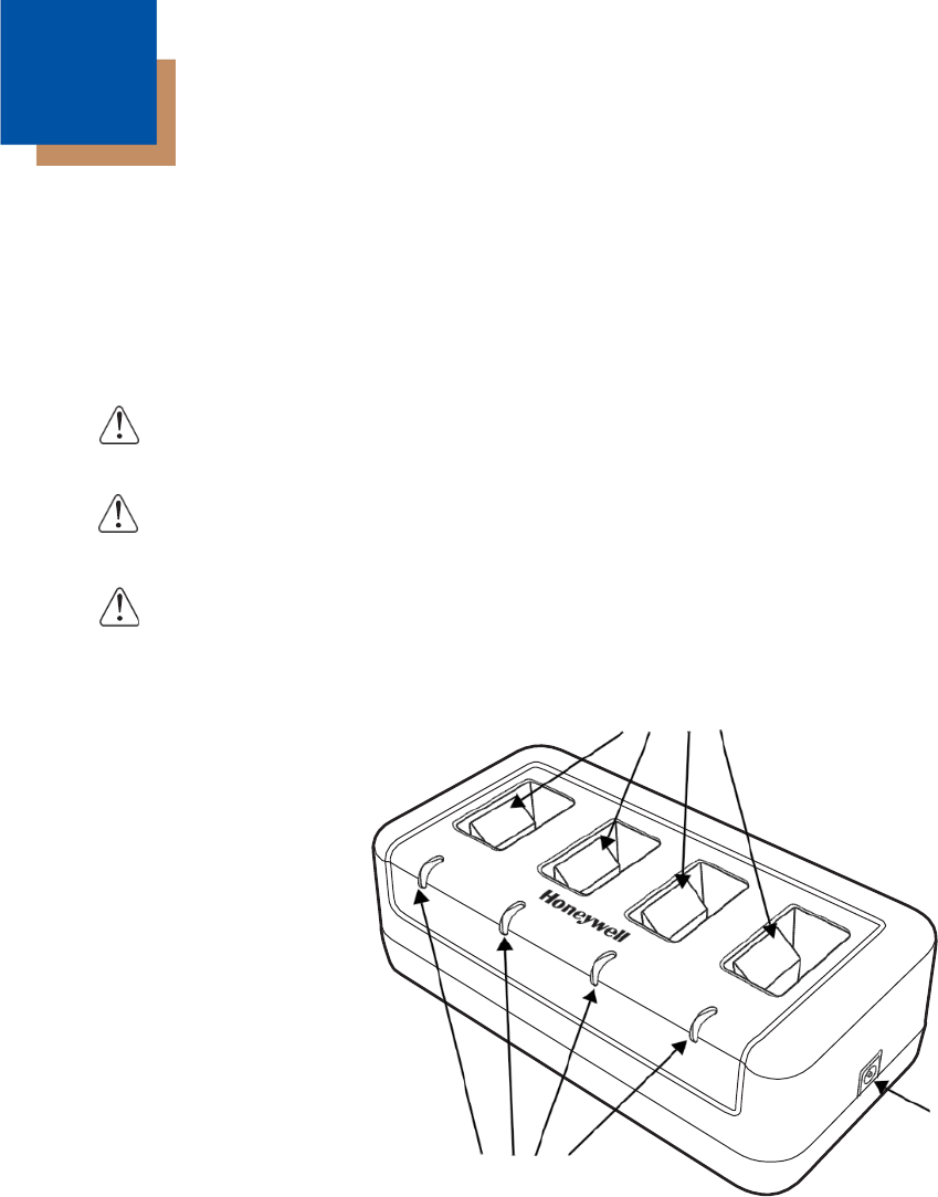
9 -1
!
Dolphin QuadCharger Device
Overview
The Dolphin QuadCharger device is a four-slot charging station that charges up to four Li-ion battery
packs in an average of 5 1/2 hours for a fully depleted battery. It takes less time if the battery has some
charge. For more details about charging, see Battery Charging on page 11-2.
We recommend use of Honeywell peripherals, power cables, and power adapters. Use of any non-Honeywell
peripherals, cables, or power adapters may cause damage not covered by the warranty.
We recommend use of Honeywell Li-Ion battery packs. Use of any non-Honeywell battery may result in
damage not covered by the warranty.
Ensure all components are dry prior to mating batteries with peripheral devices. Mating wet components may
cause damage not covered by the warranty.
QuadCharger Device
Charging Slots
Power Supply Connector
Status LEDs
Charging Slots
The charger contains four charging slots. Each slot holds one battery. When a battery is placed
in a slot, it immediately begins charging and its Status LED lights.
Status LEDs
A status LED is located at the end of each of the four battery slots. The color of the LED
indicates the charge status of the battery in the slot.
Green The battery has completed its charge cycle and is ready for use.
Red The battery is charging.
10
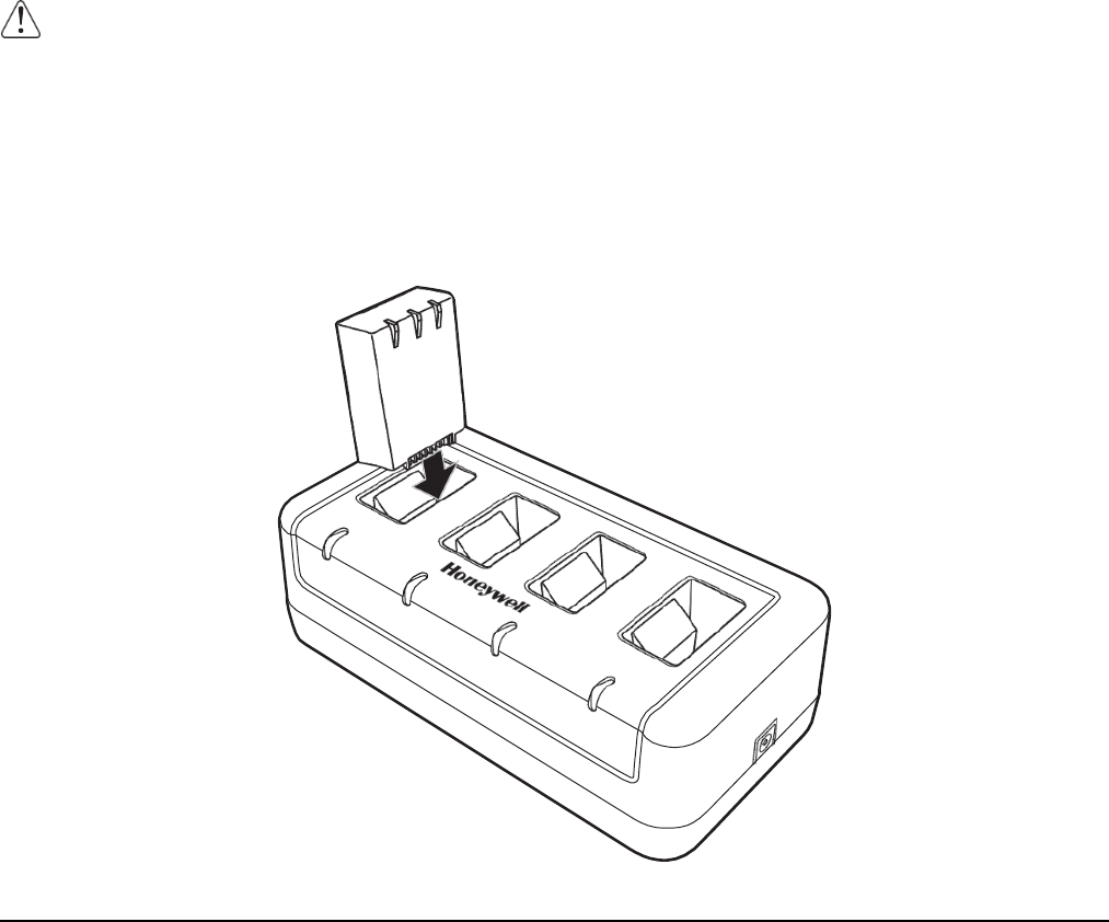
9 -1
Power Supply Connector
Use this connector to attach the power supply to the charger. The universal power supply accepts input
voltages between 90–265 volts.
Battery Charging
Charging Process
This charger charges Dolphin 6500 Li-Ion 3300mAh packs in an average of 5 1/2 hours for a fully depleted
battery. It takes less time if the battery has some charge. Each charging slot works independently of the
other three. As battery packs charge, the charging circuitry follows the two-step charging process (CC-
CV) that is recommended for Li-Ion batteries. The process monitors changes in temperature, current, and
voltage.
Temperature
The six-hour charge time applies when batteries are charged within the recommended temperature range
of 50° to 95° F (10to 35C). Temperature has a significant effect on charging. For best results, battery
packs should be at room temperature before inserting in the charger.
When the battery temperature exceeds 40C, the charger may exceed the stated six-hour charge
time. The charger stops charging if the battery temperature is greater than 40C, but will begin
charging again when the battery temperature is less than 40C.
Charging Batteries
1. Supply the charger with power.
2. Insert batteries into the appropriate slots.
The Status LED for each slot turns red to indicate that the battery is properly seated and has begun
a charge cycle.

9 -1
3. When the Status LED turns green, the battery in the slot has completed charging.
Recommendations for Storing Batteries
To maintain top performance from batteries, follow these storage guidelines:
• Avoid storing batteries outside of the specified temperature range of -4 to 104°F (-20 to 40°C) or in
extremely high humidity.
• For prolonged storage, it is recommended that the battery be at a 40% - 50% charge level, be removed
from the device, and stored in a controlled temperature environment. Following these
recommendations will maximize battery life.
Troubleshooting
If you encounter problems with the charger, refer to chart below for possible solutions. If problems persist,
contact Product Service and Repair (see page 14-1).
Problem
Issue
The Status LED does not come on
when I insert a battery pack into a
slot.
Check the power connections to the device; make sure the battery
pack is properly seated.

9 -1
Technical Specifications
Structural
Dimensions
7.3 in. long X 3.7 in. wide X 2.4 in. high
(18.5 cm. X 9.4 cm. X 6.1 cm.)
Weight
11.5 oz. (325g)
Material
Case: Polycarbonate
Color: Black
Capacity
Supports up to four Li-Ion battery packs
Environmental
Operating Temperature
32° to 104°F (0° to 40°C)
Storage Temperature
-4° to +140°F (-20° to +60°C)
Charging Temperature
32° to 104°F (0° to 40°C)
Electrical Static
Discharge
Air:
± 15k Vdc
Direct: ± 8k Vdc
Humidity
90% relative humidity (non-condensing)
Power Supply
Input (Universal)
100V-240V, 1.2 A
50-60Hz
Included
Output
5Volts DC, 4.0 A
Charging
Standard Charge
3300mAh - 5 /12 hours for a fully depleted battery
Status LEDs
Green: charged
Red: charging
Agency Approvals
Power Supply
UL listed
TUV licensed
Power Supply compliant to FCC part 15, Class B
Charging
CE Marking
CISPR Pub 22
Fire Retardant
UL94 V-0

9 -1
!
!
Dolphin 6500 Net Base Device
Overview
The Net Base enables up to four Dolphin 6500 mobile computers to communicate with a host device
over an Ethernet network. In addition, the Net Base provides a second RJ45 Ethernet port for connec-
tion to an additional device such as a printer, workstation, eBase, or another Net Base.
We recommend use of Honeywell peripherals, power cables, and power adapters. Use of any non-Honeywell
peripherals, cables, or power adapters may cause damage not covered by the warranty.
Unpacking the Net Base
Open the shipping box and inspect the package to see that the following standard items are included:
• One Dolphin Net Base Ethernet cradle
• One universal AC/DC power adapter for the Dolphin Net Base
• One power cord
You will also need to provide a standard CAT-5 Ethernet network cable. These items are needed to set
up and operate the Net Base. If any items are missing or anything appears to be damaged, contact your
Customer Account Representative.
Keep the original packaging in case you need to return the Net Base for service or to store the Net Base
while not in use.
Charge Time
The base supplies power to the intelligent battery charging system in all Dolphin terminals, which senses
when a full charge has been achieved and switches to a trickle charge to maintain the full charge.
As battery packs charge, the charging circuitry follows the two-step charging process (CC-CV) that is
recommended for Li-ion batteries. The process monitors changes in temperature, current, and voltage.
The main battery of each terminal charges in 4 hours for the standard 3.7V battery or 6 hours for the
extended 3.7V battery.
Convenient Storage
Intelligent battery charging makes this base a safe and convenient storage receptacle for your Dolphin
terminal.
Capacity
The base can hold up to 4 Dolphin terminals. Each charging well charges each terminal independently of
the other wells.
We recommend use of Honeywell Li-ion battery packs. Use of any non-Honeywell battery may result in
damage not covered by the warranty.
We recommend use of Honeywell peripherals, power cables, and power adapters. Use of any non-Honey-
well peripherals, cables, or power adapters may cause damage not covered by the warranty.
11
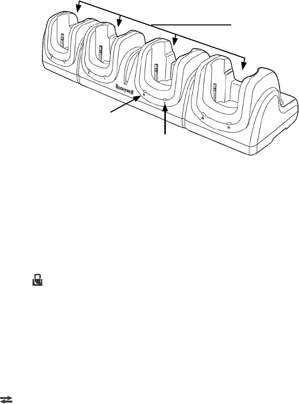
9 -1
Parts and Functions
Front Panel
Terminal Wells
The Net Base contains four terminal wells. Each well has its own dedicated Power/Dock LED
and COMM LED indicator.
Place the Dolphin terminal in any one of the four wells to communicate with a host device,
power the terminal, and charge the installed battery pack. The Net Base completely charges
the main battery in a Dolphin terminal in 4 hours for the standard 3.7V battery or 6 hours for
the extended 3.7 battery.
Power/DOCK LED
Indicates if power is supplied to the Net Base and if a terminal is docked properly in the terminal
well. Each terminal well has its own dedicated Dock LED.
This color means…
Red
The Net Base has power but no terminal is docked.
Green
The Net Base has power and the terminal is properly seated in the base.
COMM LED
The COMM LED indicates the status of connection and data transfer between the Dolphin
terminal and the Net Base. Each terminal well has its own dedicated COMM LED.
When the Dolphin terminal is docked:
This color
and status
means…
Green
Solid
A connection has been established between the Dolphin terminal
and the Net Base.
Green
Flashing
Data transfer in progress.
Note: The COMM LED does not necessarily indicate the Net Base and terminal are connected to a valid Ethernet
link. For more information, see RJ45 Ethernet Ports on page 12-3.
Terminal Wells
Power/Dock LED
COMM LED
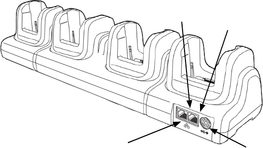
9 -1
Back Panel
Green LED Yellow LED
Two RJ45 Ethernet Ports DC Power Jack
DC Power Jack
Use the power cable from Honeywell that comes with the Net Base to supply power to this
power jack. For more information, see Power on page 12-4.
RJ45 Ethernet Ports
The Net Base contains two RJ45 Ethernet ports. You can connect the Net Base to an Ethernet-
compliant device to facilitate Ethernet communication to and from the terminal by plugging a
standard CAT-5 Ethernet cable into one of the two Ethernet ports provided. The second RJ45
Ethernet port can be used for connection to an additional device such as a printer, workstation,
eBase, or another Net Base.
Note:
The Net Base does not use a Spanning Tree Protocol (STP). When both RJ45 Ethernet ports
are used, do not connect both Net Base interfaces to the same layer 2 LAN.
Each Ethernet port has a dedicated green and yellow status LED.
This color
and status
means…
Green
Flashing
Data transfer is in progress.
Solid
A connection has been established between the Net Base and
the Ethernet.
Yellow
Solid
Ethernet is connected at 100T.
Off
Ethernet is connected at 10T.
Note: The terminal and Ethernet link must be set up properly to allow the terminal to communicate to other devices
and/or the Internet. For more information, see Connecting the Dolphin Terminal to the Net Base on page 12-5.
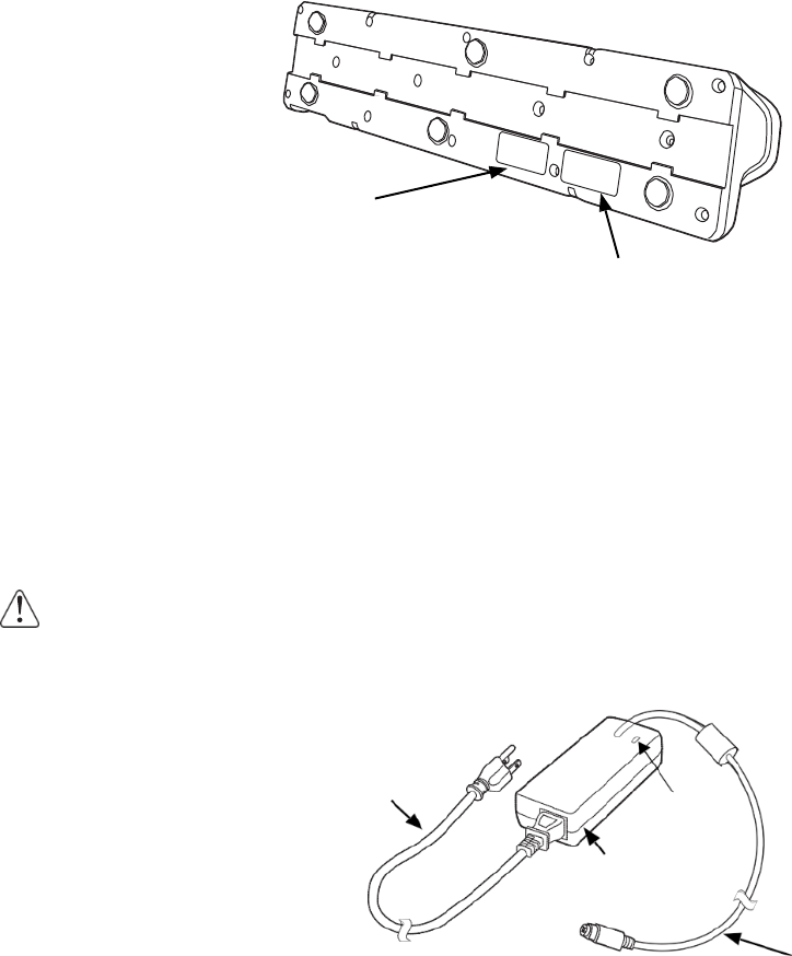
Bottom Panel
For details on how to mount the Net Base, see Mounting the Net Base on page 12-6.
MAC Address Label
Power
The terminal requires 12 Volts DC input for communications and battery charging; the power adapter on
the power cable converts the voltage from the power source to 12 volts DC. Only the Honeywell 12V/
8.5A power supply provided with the Net Base converts the voltage appropriately. The operating temper-
ature range is -10° to 50°C (14° to 122°F).
Honeywell recommends that you leave the Net Base connected to its power source at all times, so that it
is always ready to use.
We recommend use of Honeywell peripherals, power cables, and power adapters. Use of any non-Honeywell
peripherals, cables, or power adapters may cause damage not covered by the warranty.
Connecting Power to the Net Base
A/C Power Cord LED
Power
Adapter
1. Plug the A/C power cord into the power adapter.
Power Connector Cable
2. Plug the power connector cable into the power connector on the back of the Net Base.
3. Plug the A/C power cord into a standard wall outlet. The LED on the Power Adapter illuminates to
indicate power.
4. All four Power/Dock LEDs illuminate solid red to indicate the base has power. Terminal wells with
properly docked Dolphins indicate power with a green LED.
5. The base is ready to begin charging terminals.
Serial Number and Compliance
Label
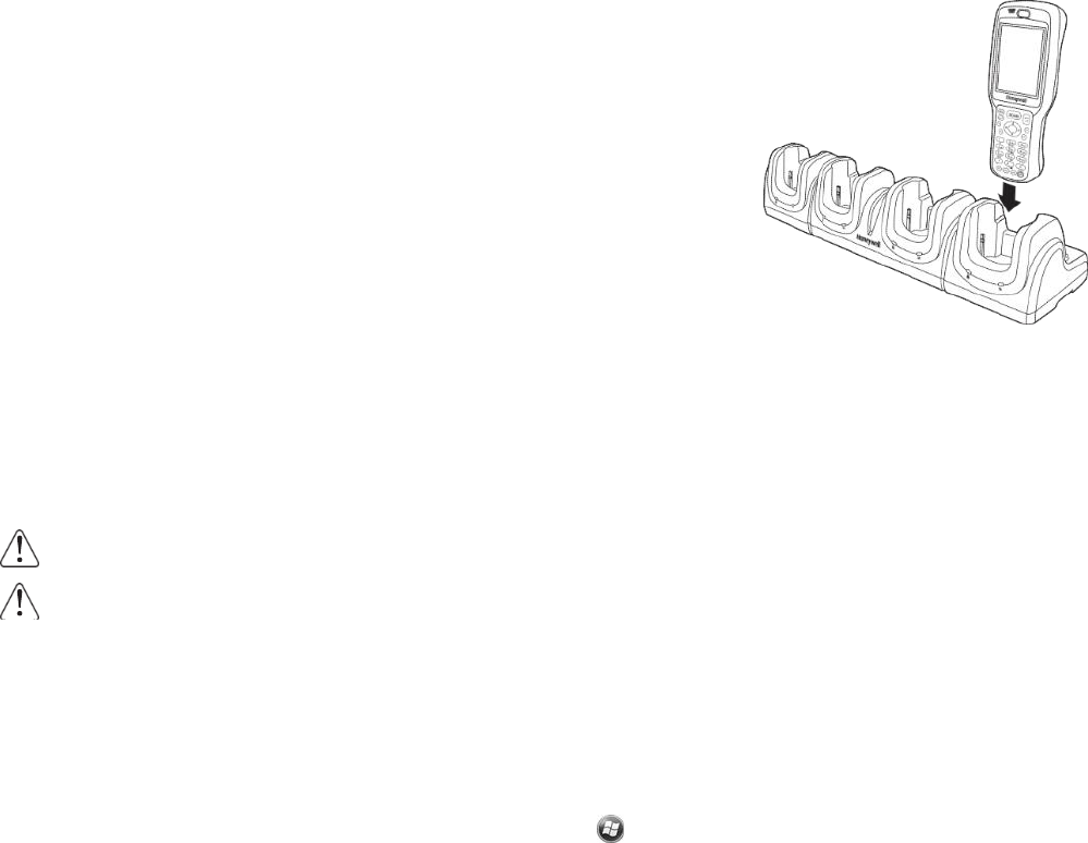
Charging the Main Battery
The base provides power to the Dolphin terminals and allows the
charging of the main batteries in the terminals. The main battery of
each terminal charges in 4 hours for the standard 3.7V battery or
5 hours for the extended 3.7V battery. The intelligent battery charging
system incorporated into all Dolphin terminals prevents overcharging,
which means that Dolphin terminals may be stored in the base indefi-
nitely without damage to the terminals, battery packs, or the base.
To Power a Terminal and Charge its Main Battery
1. Install the main battery pack in the terminal; see Install the Main
Battery on page 2-1.
2. Verify the base has power. If the Power/Dock LEDs are not illuminated, see Connecting Power to
the Net Base on page 12-4.
3. Slide the Dolphin terminal into one of the four terminal wells. The the Power/Dock LED for the well
changes to green. Charging begins immediately if required by the Dolphin terminal.
Make sure the terminal is dry before placing it in the Net Base. Do NOT place a wet terminal in the Net Base!
Doing so may cause damage not covered by the warranty.
We recommend use of Honeywell Li-Ion battery packs. Use of any non-Honeywell battery may result in dam-
age not covered by the warranty.
Communication
Software Requirements
Before you connect the Dolphin terminal to the Net Base, make sure you have the most current software
installed. To check the terminal’s system information, tap > Power Tools > SysInfo.
• The Kernel version must be 28.04 or later in terminals running Windows Embedded Handheld 6.5
Classic.
• In terminals running Windows CE 5.0, the kernel version must be 23.08 Service Pack 8 or later.
Applications on the Dolphin Terminal
Applications running on the Dolphin terminal when it is connected to the Net Base should be designed
specifically for a partially connected network. For more details, please refer to the Best Practices for Par-
tially Connected Networks document available at www.honeywellaidc.com.
Connecting the Dolphin Terminal to the Net Base
By default, the Dolphin terminal is configured to obtain IP addresses automatically using a DHCP server.
This means that in most cases, you would simply plug-and-play the unit.
1. Verify the base has power. If the Power/Dock LEDs are not illuminated, see Connecting Power to
the Net Base on page 12-4.
2. Plug the CAT-5 Ethernet cable into one of the RJ45 connectors on the back of the Net Base.

3. Plug the Ethernet cable into the network.
4. Insert the Dolphin into one of the terminal wells. The DOCK LED for the well changes from red to
green and the connection icon on the Dolphin’s title bar changes from
x
to .
5. By default, the DHCP server assigns a unique IP address to each of the Dolphin terminals docked in
the Net Base. This IP address can be used by any application on the Dolphin terminal.
Note: Instead of using the default for DHCP assigned IP addresses, the Dolphin terminal can use a statically
assigned IP address. See standard Microsoft Windows Mobile documentation for how to assign a static IP
address to a network adapter. In this case, set a static IP address for the adapter named "SMC95001 USB2.0
FAST Ethernet Drive".
Displaying the Net Base Terminal Well and Dolphin IP Address
Once the Dolphin terminal establishes communication, it uses the unique IP address assigned to the ter-
minal well it is docked in on the Net Base. If four Dolphin terminals are successfully connected, then four
different IP addresses are assigned to the adapter associated with the Dolphin terminal.
1. Tap > Power Tools > Network Utilities > IPConfig.
2. Change the Adapter to SMC95001.
3. On the Input tab, tap the Display full configuration button.
4. The Dolphin terminal retrieves and displays the IP configuration for the entire Dolphin terminal and
the Net Base terminal well where the Dolphin is docked.
5. Locate the IpAddress field in the IP configuration list.
Mounting the Net Base
Set the Net Base on a dry, stable surface, such as a desktop or workbench near an electrical outlet. Be
sure to provide enough workspace with good lighting for the user to view and operate the Dolphin termi-
nal while it is in the Net Base. When choosing a location, bear in mind that the mounting location must
allow users easy access to the terminal wells, the Ethernet ports, and the power jack.
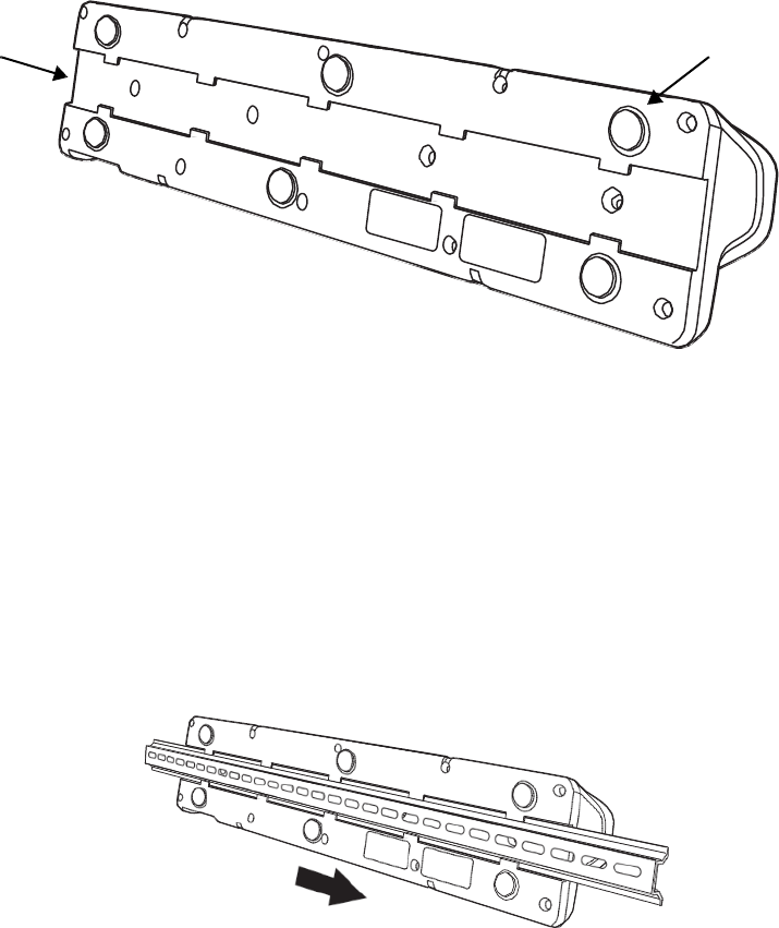
Bottom Panel
DIN Rail Slot Rubber Feet, Qty. 6
Desk Mounting
The DIN Rail (7.5 X 35 mm) slot on the bottom panel enables secure mounting on a horizontal surface.
Hardware Required
• 3/16 in. dia x 5/8 in. long pan head screw
• 1/2 in. OD x 7/32 in. ID x 3/64 in. thick
• 3/16 in. dia nut
Installing the DIN Rail
1. Slide the DIN Rail into the DIN Rail slot on the bottom panel of the base.
2. Turn the base and DIN Rail right side up.
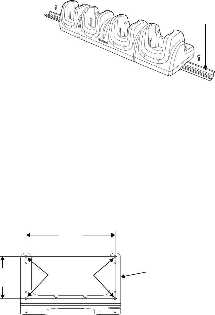
3. Then, using the appropriate nuts and bolts, secure the DIN Rail to a stable, flat horizontal surface.
DIN Rail (7.5 X 35 mm)
Wall Mounting
The optional wall mount bracket enables secure mounting of the base on a vertical surface. The wall
mount bracket can be used in conjunction with the DIN rail but does not require the DIN Rail for use.
Hardware (Provided)
• M3 x 9 mm self-tapping screws, #2 Phillips, Qty. 4
• 3/8 in. x 4 in. round head toggle bolt, 2-5/8 in. usable length, Qty. 4
• 3/8 in. x 2 1/2 in. length Hex Head Lag Screw, Qty. 4
Tools Required
• Drill
• 7/8 in. Drill Bit (for hollow wall installations) or
1/4 in. Drill Bit (for wood stud installation)
• Phillips Screw Driver
Hollow Wall Installation
1. Drill four pilot holes in the wall using a 7/8 in. drill bit.
13.78 in.
[35 cm]
6.5 in.
[16.5 cm]
Wall Mount Holes Wall Mount Bracket
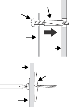
2. Slide the bolt through the wall bracket, and thread the toggle nut onto
the bolt.
3. Press the ends of the toggle nut together, and insert the bolt/nut into the
pilot hole until the nut clears inside wall surface. The toggle nut should
spring open preventing the screw from being removed.
4. Repeat steps 2 and 3 for each of the remaining mounting holes.
5. Tighten all four bolts to secure the bracket to the wall.
6. Once the bracket is installed, secure the base to the wall bracket, see
Securing the Base to the Wall Bracket for detailed instructions.
Wood Stud Installation
1. Drill four pilot holes in the wall/wood stud using the 1/4 in. drill bit.
Bolt
Bracket
Wall
Bracket
Toggle Nut
Wall
Open
Toggle Nut
2. Secure the bracket to the wall using the four Hex Head Lag Screws provided.
3. Once the bracket is installed, secure the base to the wall bracket, Securing the Base to the Wall
Bracket for detailed instructions.
Securing the Base to the Wall Bracket
You can secure the base to the wall bracket using the optional DIN rail.
Hardware Required
• DIN Rail, Qty. 1
• 3/16 in. dia x 5/8 in. long pan head screw, Qty. 2
• 1/2 in. OD x 7/32 in. ID x 3/64 in. thick washer, Qty. 2
• 3/16 in. dia nut, Qty. 2
1. Position the DIN Rail on the wall bracket, as shown below.
2. Slide the screw through the slot on the DIN Rail and the mounting hole in the bracket.
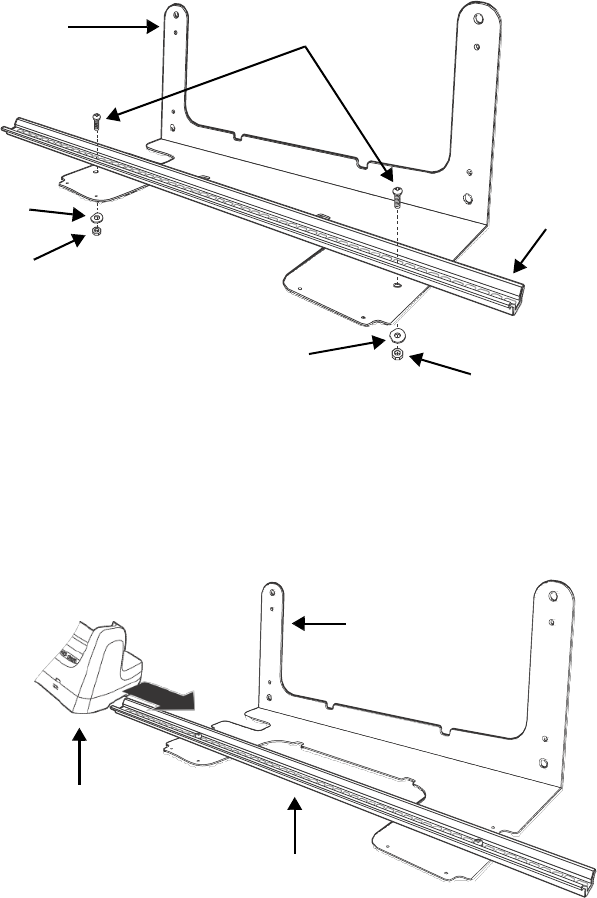
3. Slide the washer onto the screw and tighten the nut to secure the assembly.
Wall Bracket, Qty. 1 Screw, Qty. 2
Washer, Qty. 1
Nut, Qty. 1
DIN Rail, Qty. 1
Washer, Qty. 1
Nut, Qty. 1
4. Remove the rubber feet on the bottom of the Net Base.
5. Slide the base onto the DIN Rail using the slot on the bottom of the base.
Wall Bracket
Wall Bracket
DIN Rail
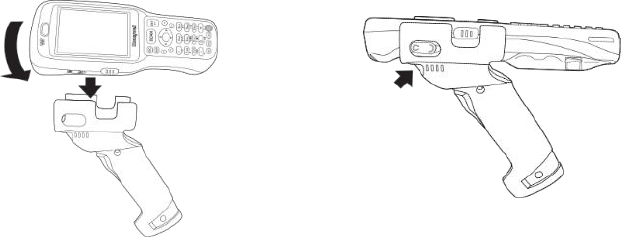
Overview
The optional slide-on handle provides a productivity-enhancing solution for applications that require high
volume scanning, such as inventory management and stock replenishment.
Removing the Hand Strap
Prior to installing the Dolphin 6500 handle on the terminal, you must remove the hand strap.
1. Release the hook and loop portion of the strap and feed it through the opening at the bottom end of
the terminal.
2. Remove the two screws that secure the top of the strap to the terminal.
3. Store the strap and screws for future use.
Installing the Handle/Removing the Handle
1. Place the terminal at an angle and snap it into place lining up the green buttons and headset jack on
the sides of the terminal with the openings in the handle.
2. Using the attached screws, secure the handle to the terminal. The screws line up with the screw
holes from the hand strap. To remove terminal, remove the screws and twist the terminal slightly
and pull up.
Tighten screws

Technical Assistance
If you need assistance installing or troubleshooting your device, please contact us by using one of the methods below:
Knowledge Base: www.hsmknowledgebase.com
Our Knowledge Base provides thousands of immediate solutions. If the Knowledge Base cannot help, our Technical Support
Portal (see below) provides an easy way to report your problem or ask your question.
Technical Support Portal: www.hsmsupportportal.com
The Technical Support Portal not only allows you to report your problem, but it also provides immediate solutions to your
technical issues by searching our Knowledge Base. With the Portal, you can submit and track your questions online and send
and receive attachments.
Web form: www.hsmcontactsupport.com
You can contact our technical support team directly by filling out our online support form. Enter your contact details and the
description of the question/problem.
Telephone:
www.honeywellaidc.com/locations
For our latest contact information, please check our website at the link above.
Product Service and Repair
Honeywell International Inc. provides service for all of its products through service centers throughout the
world. To obtain warranty or non-warranty service, please visit www.honeywellaidc.com and select
Support > Contact Service and Repair to see your region's instructions on how to obtain a Return
Material Authorization number (RMA #). You should do this prior to returning the product.
Limited Warranty
Honeywell International Inc. ("HII") warrants its products and optional accessories to be free from defects
in materials and workmanship and to conform to HII’s published specifications applicable to the products
purchased at the time of shipment. This warranty does not cover any HII product which is (i) improperly
installed or used; (ii) damaged by accident or negligence, including failure to follow the proper
maintenance, service, and cleaning schedule; or (iii) damaged as a result of (A) modification or alteration
by the purchaser or other party, (B) excessive voltage or current supplied to or drawn from the interface
connections, (C) static electricity or electro-static discharge, (D) operation under conditions beyond the
specified operating parameters, or (E) repair or service of the product by anyone other than HII or its
authorized representatives.
This warranty shall extend from the time of shipment for the duration published by HII for the product at
the time of purchase ("Warranty Period"). Any defective product must be returned (at purchaser’s
expense) during the Warranty Period to HII factory or authorized service center for inspection. No product
will be accepted by HII without a Return Materials Authorization, which may be obtained by contacting
HII. In the event that the product is returned to HII or its authorized service center within the Warranty
Period and HII determines to its satisfaction that the product is defective due to defects in materials or
workmanship, HII, at its sole option, will either repair or replace the product without charge, except for
return shipping to HII.
EXCEPT AS MAY BE OTHERWISE PROVIDED BY APPLICABLE LAW, THE FOREGOING
WARRANTY IS IN LIEU OF ALL OTHER COVENANTS OR WARRANTIES, EITHER EXPRESSED OR
IMPLIED, ORAL OR WRITTEN, INCLUDING, WITHOUT LIMITATION, ANY IMPLIED WARRANTIES
OF MERCHANTABILITY OR FITNESS FOR A PARTICULAR PURPOSE, OR NON-INFRINGEMENT.
HII’S RESPONSIBILITY AND PURCHASER’S EXCLUSIVE REMEDY UNDER THIS WARRANTY IS
LIMITED TO THE REPAIR OR REPLACEMENT OF THE DEFECTIVE PRODUCT WITH NEW OR
REFURBISHED PARTS. IN NO EVENT SHALL HII BE LIABLE FOR INDIRECT, INCIDENTAL, OR
CONSEQUENTIAL DAMAGES, AND, IN NO EVENT, SHALL ANY LIABILITY OF HII ARISING IN
CONNECTION WITH ANY PRODUCT SOLD HEREUNDER (WHETHER SUCH LIABILITY ARISES

FROM A CLAIM BASED ON CONTRACT, WARRANTY, TORT, OR OTHERWISE) EXCEED THE
ACTUAL AMOUNT PAID TO HII FOR THE PRODUCT. THESE LIMITATIONS ON LIABILITY SHALL
REMAIN IN FULL FORCE AND EFFECT EVEN WHEN HII MAY HAVE BEEN ADVISED OF THE
POSSIBILITY OF SUCH INJURIES, LOSSES, OR DAMAGES. SOME STATES, PROVINCES, OR
COUNTRIES DO NOT ALLOW THE EXCLUSION OR LIMITATIONS OF INCIDENTAL OR
CONSEQUENTIAL DAMAGES, SO THE ABOVE LIMITATION OR EXCLUSION MAY NOT APPLY TO
YOU.
All provisions of this Limited Warranty are separate and severable, which means that if any provision is
held invalid and unenforceable, such determination shall not affect the validity of enforceability of the
other provisions hereof. Use of any peripherals not provided by the manufacturer may result in damage
not covered by this warranty. This includes but is not limited to: cables, power supplies, cradles, and
docking stations. HII extends these warranties only to the first end-users of the products. These
warranties are non-transferable.
Limited Warranty Duration
• The duration of the limited warranty for terminals with an integrated imager is one year.
• The duration of the limited warranty for touch screens is one year.
• The duration of the limited warranty for Dolphin HomeBase, Dolphin Mobile Mount, Dolphin
ChargeBase, Dolphin Mobile Charger, and Dolphin QuadCharger is one year.
• The duration of the limited warranty for batteries is one year.
Use of any battery from a source other than Honeywell may result in damage not covered by the
warranty. Batteries returned to Honeywell International Inc. in a reduced state may or may not be
replaced under this warranty. Battery life will be greatly increased when following the battery
instructions in this user’s guide.
How to Extend Your Warranty
Honeywell International Inc. offers a variety of service plans on our hardware products. These
agreements offer continued coverage for your equipment after the initial warranty expires. For more
information, contact your Sales Representative, Customer Account Representative, or Product Service
Marketing Manager from Honeywell International Inc., or your Authorized Reseller.