Honeywell 660W HSOM660 User Manual Installation Guide
Honeywell International Inc HSOM660 Installation Guide
Contents
- 1. User Manual
- 2. User Manual_Installation Guide
- 3. User manual
User Manual_Installation Guide

Page 1 of 7
Honeywell Internal
HSOM660
Installation guide.
Contains Information proprietary to
Honeywell, Inc.

Page 2 of 7
Honeywell Internal
Dolphin® SOM Installation Description
1.0 SYSTEM OVERVIEW
The Dolphin® SOM Radio Module is offered with “Android 7.1” based operating
system. The hardware will be made up of the basic system
components shown
in Figure 1 below. The unit will be available per the following matrix:
The SOM module has radios for LTE (+ 2G, 3G, 4G), GPS, 802.11a/b/g/n/ac
WLAN and Bluetooth 2.0/4.0/5.0. The WLAN and Bluetooth radio modules in
the product will have a shared antenna. Similar to a Smartphone, the device
can be used up to head or
in speakerphone mode.
2.0 Baseline Terminal Features
The following is a detailed list of the base terminal features.
•
Operating System Android 7.1 or later
•
Qualcomm
®
SDM660 Octa Core 2.2GHz Processor
•
RAM Memory: 4GB LPDDR4 SDRAM (discrete)
•
FLASH Memory: 32 GB MLC eMMC Managed NAND
•
4-bit micro Secure Digital Card Interface
•
Dual SIM Support
•
High Speed USB Client / High Speed USB Host / Charging Connector (IO connector - 10
pos)
•
Integrated gyroscope
•
Bluetooth Radio with Internal Antenna
•
802.11a/b/g/n/ac Radio with Internal Antenna
•
GPS Support with Internal Antenna
•
WWAN Radio features air interface support for a single global SKU with support for voice &
internal antennas:
3.0 Regulatory Compliance
This product regulatory compliance information is shown in Regulatory sheet document.
Page 3 of 7
Honeywell Internal
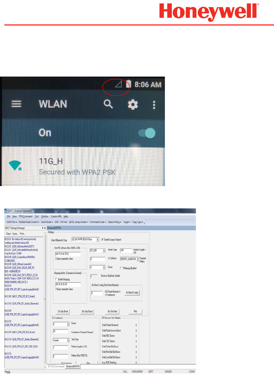
4.0 User Utility
Support end user mode and RF continuous transmit mode with the driver and tool.
User mode:
RF mode:
WAN
Page 4 of 7
Honeywell Internal
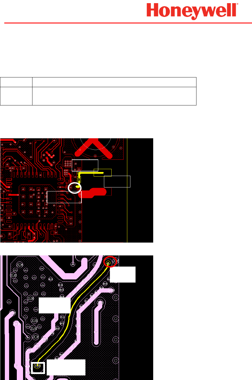
5.0 Layout Instruction and Antenna
OEM Integrators must follow the instructions and limitations for the chosen antenna schemes
exactly as stated below..
Antenna PIFA antenna
RF trace Corresponding 50-ohm characteristic impedance,
the length and
routing as following structure.
WLAN chain0/BT:
Top layer:
Inner layer
Maintains a solid ground plane under the RF signal trace, and use strip-line structure for inner layer
of the PCB, and ensure the ground return path is uninterrupted.
305 mil
SOM
pin
120mi
to top
to inner
ANT
Page 5 of 7
Honeywell Internal
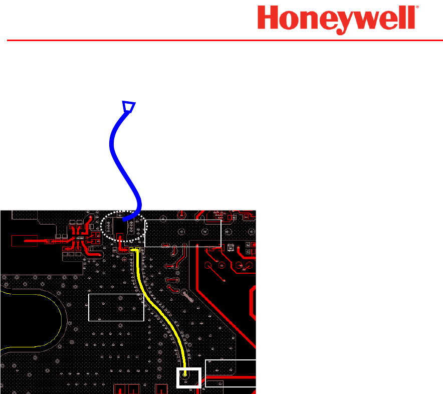
WLAN chain1:
Top layer:
Maintains a solid ground plane under the RF signal trace, and use strip-line structure for inner layer
of the PCB, and ensure the ground return path is uninterrupted.
504 mil
50 ohms Coaxial
cable to antenna,
1020 mil.
Connector
SOM pin

Page 6 of 7
Honeywell Internal
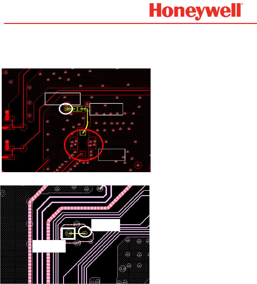
WAN main:
Top layer:
Inner1 layer:
Inner2 layer:
Maintains a solid ground plane under the RF signal trace, and use strip-line structure for inner layer
of the PCB, and ensure the ground return path is uninterrupted.
95
mil
to inner
1
ANT
to inner
2
to
top
59 mil
to inner
1
SOM
pin
375 mil
Page 7 of 7
Honeywell Internal
WAN Aux (RX only):
Top layer:
Inner layer:
Maintains a solid ground plane under the RF signal trace, and use strip-line structure for inner layer
of the PCB, and ensure the ground return path is uninterrupted.
ANT
137 mil
to inner
to
top
SOM
pin