Honeywell 7400-352 Wireless Hand Held Computer/ Bar Code Scanner User Manual Manual
Honeywell International Inc Wireless Hand Held Computer/ Bar Code Scanner Manual
Manual
Dolphin® 7400
Hand Held Computer
User’s Guide
PRELIMINARY

Patents
The Dolphin 7400 mobile computer is covered by the following U.S Patent:
D439,898 S.
The IMAGETEAM 4250 image engine is covered by one or more of the following
U.S. Patents: 3,991,299; 4,570, 057; 5,021,642; 5,038,024; 5,081,343;
5,095,197; 5,144,119; 5,144,121; 5,182,441; 5,187,355; 5,187,356; 5,218,191;
5,233,172; 5,258,606; 5,286,960; 5,288,985; 5,420,409; 5,463,214; 5,541,419;
5,569,902; 5,591,956; 5,723,853; 5,723,868; 5,773,806; 5,773,810; 5,780,834;
5,784,102; 5,786,586; 5,825,006; 5,837,985; 5,838,495; 5,900,613; 5,914,476;
D400,199; 5,292,418; 5,932,862; 5,942,741; 5,949,052; 5,965,863; 5,992,744;
6,045,047; 6,060,722.
Other U.S. and foreign patents pending.
Disclaimer
Hand Held Products reserves the right to make changes in specifications and
other information contained in this document without prior notice, and the reader
should in all cases consult Hand Held Products to determine whether any such
changes have been made. The information in this publication does not represent
a commitment on the part of Hand Held Products.
Hand Held Products shall not be liable for technical or editorial errors or omissions
contained herein; nor for incidental or consequential damages resulting from the
furnishing, performance, or use of this material.
This document contains proprietary information which is protected by copyright.
All rights are reserved. No part of this document may be photocopied,
reproduced, or translated into another language without the prior written consent
of Hand Held Products.
2001 Hand Held Products All rights reserved.
Web Address: http://www.handheld.com

iii
•
•
•
•
•
•
7DEOHRI&RQWHQWV
Chapter 1 Introduction ............................................................... 7
Safety ..................................................................................................8
Required Safety Labels.........................................................8
Batch Terminals.....................................................................8
If Your Dolphin 7400 has a radio.........................................9
FCC Compliance ...................................................................9
Regulatory and Safety Agency Approvals ........................11
Batteries............................................................................................12
Care and Cleaning of the Dolphin .................................................12
Chapter 2 Getting Started......................................................... 13
Accessories for the Dolphin ............................................................13
Dolphin 7400 Models and Options.................................................14
Image Engine Options and Bar Code Symbologies Supported...14
Using Dolphin 7400 for the First Time..........................................15
Chapter 3 Dolphin 7400 Overview .......................................... 25
System Features...............................................................................25
Processor ..............................................................................25
Operating System ................................................................25
Memory ................................................................................25
Radio options .......................................................................25
Front Panel Features.......................................................................26
LEDs .....................................................................................26
1/4 VGA Display..................................................................27
ON/SCAN Key .....................................................................27
Cursor Key...........................................................................27
Audio Signals .......................................................................27
Keyboard..............................................................................27
RF Antenna..........................................................................28
Back Panel Features........................................................................29
Imaging Engine....................................................................29
Battery Well .........................................................................30
Hand Strap...........................................................................30
Battery Charging Contacts.................................................30
Communication................................................................................30
Micro-DB9 RS-232 Port......................................................30
IrDA Port .............................................................................30
Phone Jack ...........................................................................30

iv
•
•
•
•
•
•
Power ................................................................................................30
5 VDC Port..........................................................................30
Batteries................................................................................30
Internal NiHM Backup Battery .........................................31
Main Battery Pack...............................................................31
Managing Battery Power................................................................31
Using the Power Control Panel ..........................................32
Servicing the Battery Pack .................................................33
Charging the Battery Pack .................................................34
Storing Batteries ..................................................................34
Chapter 4 Learning to Operate Dolphin 7400.......................... 35
Entering Data...................................................................................35
Via the Touchscreen Input .................................................35
Via the Keyboard.................................................................35
Using the Image Reader......................................................35
Communication................................................................................36
Communication Media........................................................36
Software Communication Programs .................................36
Using the Keyboard.........................................................................37
Using the Cursor Keys ........................................................38
Using the Modifier Keys .....................................................39
Other Special Keys..............................................................39
Key Combinations...............................................................40
Navigating the Keyboard................................................................41
Using the Modem.............................................................................43
Chapter 5 Dolphin 7400 RF Terminal ..................................... 45
Configuring Your Dolphin 7400 RF Terminal.............................46
Client Utilities for the Dolphin 7400 802.11b Radio.........47
Configuring the Radio.........................................................48
Host Connectivity ............................................................................49
Thick-Client Terminal Emulation .....................................49
Thin-Client Terminal Emulation.......................................50
Chapter 6 HomeBase/IntelliBase/USB HomeBase................ 51
Hub of the System............................................................................51
Power Conditioning.............................................................51
Convenient Storage .............................................................51
HomeBase/IntelliBase/USB HomeBase Parts and Functions......52
Front Panel...........................................................................52
Back Panel............................................................................53
Bottom Panel of HomeBase/IntelliBase.............................55
Powering the Dolphin Terminal.....................................................56
Charging A Dolphin Terminal...........................................56

v
•
•
•
•
•
•
Deep-Cycling Batteries........................................................56
Setting Up For Communications with the HomeBase/IntelliBase57
Installing The Dolphin HomeBase/IntelliBase..................57
Configuring the Dolphin Terminal....................................59
Setting Up For Communications With The USB HomeBase ......60
Communicating with the Dolphin Terminal.................................62
Mounting the HomeBase/IntelliBase/USB HomeBase.................62
Chapter 7 7400 QuadCharger................................................... 67
Dolphin 7400 QuadCharger Parts and Function .........................67
Top Panel..............................................................................67
Rear Panel............................................................................68
Charging Batteries In The QuadCharger.....................................69
Setting Up The QuadCharger ............................................69
Supplying Power To The QuadCharger............................69
Inserting and Removing Battery Packs.............................69
Servicing The Battery Pack ................................................70
Storing Batteries ..................................................................71
Troubleshooting...............................................................................71
Chapter 8 Dolphin® Mobile IntelliBase™ .............................. 73
...............................................................................................73
Power Conditioning.............................................................73
Mobile IntelliBase Parts and Functions ........................................74
Front Panel...........................................................................74
Rear Panel............................................................................75
Bottom Panel of Mobile IntelliBase ...................................76
Powering the Dolphin Terminal.....................................................77
Charging A Dolphin Terminal...........................................77
Deep-Cycling Batteries........................................................77
Setting Up For Communications with the Mobile IntelliBase.....77
Installing The Dolphin Mobile IntelliBase........................78
Configuring the Dolphin Terminal....................................80
Chapter 9 Developing Applications......................................... 83
Chapter 10 Warranty, Support and Service.............................. 85
Limited Warranty ...........................................................................85
How Problems Should Be Handled................................................86
Return Information.........................................................................87
How To Extend Your Warranty ....................................................88
Application Support........................................................................89
Chapter 11 Appendix A ........................................................... 91

vi
•
•
•
•
•
•
Using the Modifier Keys .................................................................92
43-Key Alpha/Numeric Keyboard .................................................92
Key Combinations...............................................................93
35 Key Numeric/Alpha....................................................................94
Key Combinations...............................................................95
56 Key Full Alpha Numeric............................................................96
Key Combinations...............................................................97
Chapter 12 Appendix B............................................................ 99
Dolphin 7400 Scan Maps.................................................................99

7
•
•
•
•
•
•
Introduction
Congratulations on the purchase of your new Dolphin® 7400/7450
hand held computer. You have made a wise choice in selecting the
Dolphin, a device known worldwide for its ergonomic shape, light
weight and single-handed data collection features.
The patented shape of the Dolphin 7400 allows true, one-handed
operation and fits either hand comfortably while the Dolphin 7450’s
integrated pistol-grip handle provides comfortable ergonomics and
intuitive point-and-shoot scanning for extended periods of use.
Built to last, the Dolphin’s ruggedly built case houses a 206MHz RISC
processor and Windows® CE™ operating system that is easily
programmable with standard programming tools, like Microsoft®
Windows® CE™ eMbedded Visual Tools, which includes eMbedded
Visual C/C++® and eMbedded Visual Basic®. The terminal provides
ample, secure storage for data and applications with its 32MB RAM
and 32 MB FLASH memory configuration. Up to 256MB additional
memory for data storage is available with an optional compact flash
card.
Dolphin 7400/7450 is one of the most durable devices available, and
is designed to withstand repeated five-foot drops onto a concrete
floor. It also resists extreme temperatures, humidity levels and dust
conditions.
The Dolphin’s collection of features also includes: long-lasting Nickel
Metal Hydride (NiMH) batteries, a large easy-to-read 240 x 320 1/4
VGA backlit display that can display text or graphics, a natural scan
and viewing angle, a low-power, high-resolution digital image engine
for omni-directional and auto-discrimination decoding of linear
barcodes, Stacked Linear and matrix codes and provides OCR
(Optical Character Recognition) functionality and an optional
Advanced Long Range laser scanner. The Dolphin 74007450 may
also be equipped with an 802.11b direct sequence radio for real-time
data collection applications.
Load up the Dolphin with your custom software application and the
ultimate data collection solution for your business fits in the palm of
your hand.
The Dolphin 7400 Handheld Computer/HomeBase™ User Guide is
designed to provide you with the information you need to make the
most of your new Dolphin terminal. Sections on the basics, safety,
battery use, accessories, and service make this guide a complete
source of information.
1
8
•
•
•
•
•
•
Safety
The Dolphin 7400/7450 handheld computer meets or exceeds the requirements of
all applicable standards organizations for safe operation. However, as with any
electrical equipment, the best way to ensure safe operation is to know the
possible risks.
The following safety guidelines are designed to protect both you and others
around you. Please read them carefully before using your Dolphin terminal.
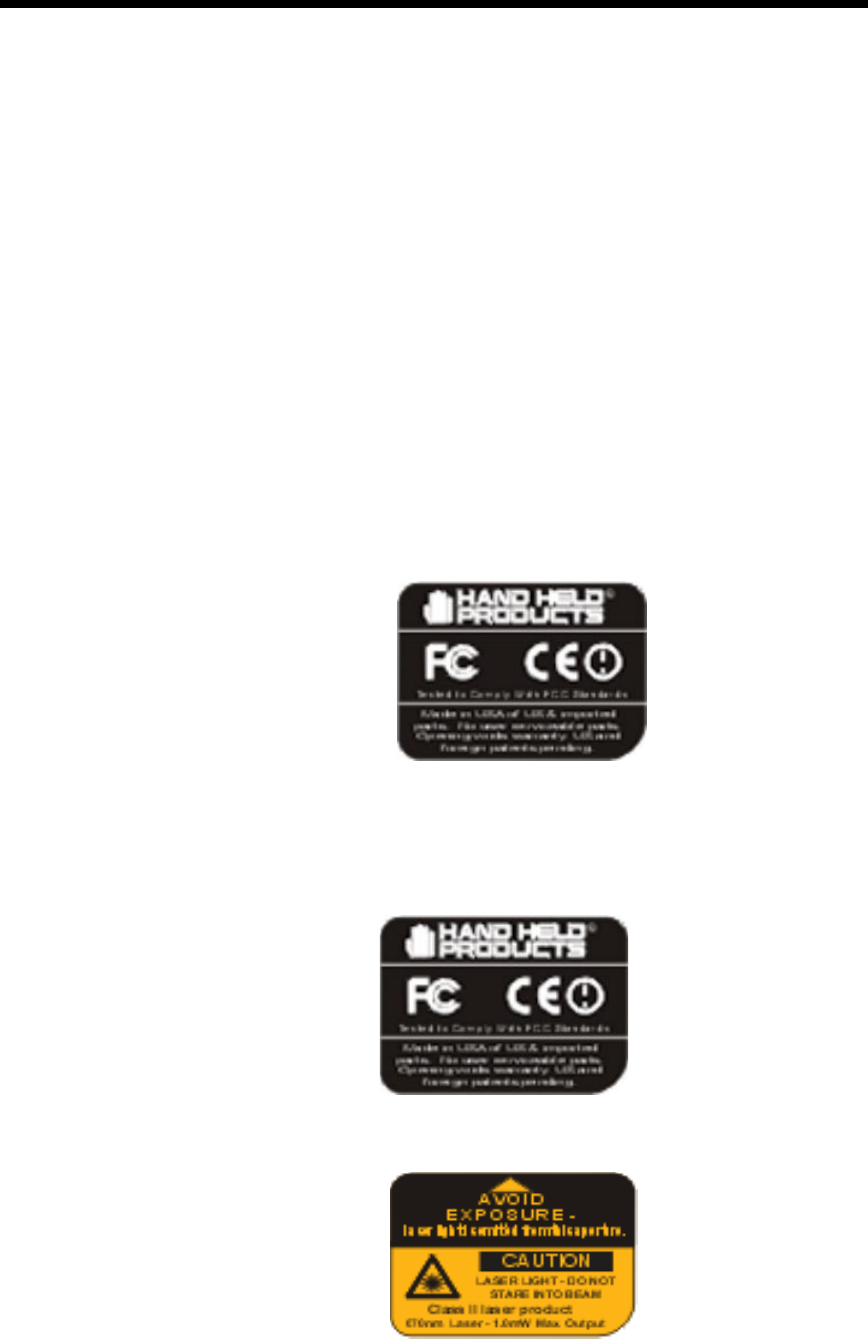
Required Safety Labels
Batch Terminals
The following is the required safety label that appears on the back panel of the
Dolphin 7400/7450 batch terminal equipped with an imager:
The following are the required safety labels that appear on the back panel of the
Dolphin 7400/7450 batch terminal equipped with a scanner:
9
•
•
•
•
•
•
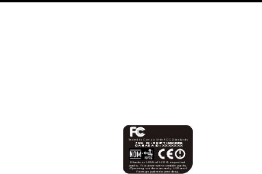
If Your Dolphin 7400/7450 has a radio
The Dolphin® 7400/7450 RF terminal is designed to comply with the most current
applicable standards on safe levels of RF energy developed by the Institute of
Electrical and Electronics Engineers (IEEE) and the American National Standards
Institute (ANSI) and has been recommended for adoption by the Federal
Communications Commission (FCC).
The following is the the required safety label that appears on the back panel of the
Dolphin 7400/7450 RF terminal:
FCC Compliance
Dolphin 7400/7450 Batch Terminal
The Dolphin 7400/7450 Batch complies with part 15 of the FCC rules. Operation
is subject to the following two conditions:
1. Devices may not cause harmful interference.
2. Devices must accept any interference received, including interference that may cause
undesired operation.
Dolphin 7400/7450 RF Terminal with Cisco 352 Radio
This device complies with Part 15 of the FCC Rules. Operation is subject to
thefollowing two conditions:(1) this device may not cause harmful interference,
and (2)this device must accept any interference received, including interference
that may cause undesired operation.
This equipment has been tested and found to comply with the limits for a Class B
digital device pursuant to Part 15 of the FCC Rules. These limits are designed to
provide reasonable protection against harmful interference in a residential
installation. This equipment generate uses and can radiate radio frequency
energy and if not installed and used in accordance with the instructions may
cause harmful interference will not occur in a particular installation. If this
equipment does cause harmful interference to radio or television reception, which
can be determined by turning the equipment off and on, the user is encouraged to
try to correct the interference by one or more of the following measures:
•
Reorient or relocate the receiving antenna.
•
Increase the separation between the equipment and receiver.

10
•
•
•
•
•
•
•
Connect the equipment into an outlet on a circuit different from that to which the
receiver is connected.
•
Consult the dealer or an experienced radio/TV technician for help.
If necessary, the user should consult the dealer or an experienced radio/television
technician for additional suggestions. The user may find the following booklet
helpful: "Something About Interference." This is available at FCC local regional
offices. Our company is not responsible for any radio or television interference
caused by unauthorized modifications of this equipment or the substitution or
attachment of connecting cables and equipment other than those specified by our
company. The correction will be the responsibility of the user. Use only shielded
data cables with this system.
CAUTION: To comply with FCC RF exposure compliance requirements, a separation
distance of at least 0 cm must be maintained between the antenna of this
device and all persons (excluding hands, wrists, feet and ankles), during normal
operation.
This device and its antenna must not be co-located or operating in conjunction with
any other antenna or transmitter.
This device is not specified or designed for body-worn configurations. Use of any
body-worn accessories may not ensure compliance with the FCC RF exposure
guidelines.

11
•
•
•
•
•
•
Regulatory and Safety Agency Approvals
The CE mark on the product indicates that the system has been tested to and
conforms with the provisions noted within the 89/336/EEC Electromagnetic
Compatibility Directive and the 73/23/EEC Low Voltage Directive.
For further information please contact,
Hand Held Products (UK) Ltd.
1 st Floor
Dallam Court Dallam Lane
Warrington, Cheshire WA2 7LT
England
Hand Held Products shall not be liable for use of our product with equipment
(i.e.,power supplies, personal computers, etc.) that is not CE marked and does
not comply with the Low Voltage Directive.
Pacemakers, Hearing Aids and Other Electrically Powered Devices
Most manufacturers of medical devices adhere to the IEC 601-1-2 standard. This
standard requires devices to operate properly in an EM Field with a strength of
3V/m over a frequency range of 26 to 1000MHz.
The maximum allowable field strength emitted by the Dolphin is 0.3V/m according
to Subpart B of Part 1 of the FCC rules. Therefore, the Dolphin RF will have no
effect on medical devices that meet the IEC specification.
Microwaves
The radio in the Dolphin RF terminal operates on the same frequency band as a
microwave oven. Therefore, if you use a microwave within range of the Dolphin
RF terminal you may notice performance degradation in your wireless network.
However, both your microwave and your wireless network will continue to
function.
Parameter Specification
U.S.A.
Canada
Europe
Others
FCC Part 15, Class B
IEC 0003
EN 55022 (CISPR22) Class B
ETS 300 826 Type Certified
EMC 89/336/EEC
EN 50082-1:1997, EN55024
RF Approvals
U.S.A
Canada
Europe
FCC Part 15.247
RSS 210 Certified
ETS 300 328 Certified

12
•
•
•
•
•
•
The Dolphin Batch terminal does not contain a radio, and therefore, is not affected
by microwave ovens.
Batteries
The following are general guidelines for the safe use and disposal of batteries:
•
Use only the battery supplied with your Dolphin or a replacement battery
supplied, recommended, or approved by Hand Held Products, Inc.
•
Replace a defective battery immediately as it could damage the Dolphin
terminal.
•
Never throw a used battery in the trash. It contains heavy metals and should be
recycled according to local guidelines.
•
Don’t short-circuit a battery or throw it into a fire. It can explode and cause
severe personal injury.
•
Excessive discharge damages a battery. Recharge the battery when your
Dolphin indicates low battery power.
•
Although your battery can be recharged many times, it will eventually be
depleted. Replace it after the recommended usage period (about 600 charge
cycles for the 2700 mAh NiMH battery) or if the battery is unable to hold an
adequate charge.
•
If you are not sure the battery or charger is working properly, please send it to
Hand Hand Products or an authorized Hand Held Products service center, for
inspection.
The Dolphin handheld computer meets or exceeds all applicable standards and
has been manufactured to the highest level of quality.
Care and Cleaning of the Dolphin
When needed, clean the image engine window and the LCD display with a clean
non-abrasive, lint-free cloth.

13
•
•
•
•
•
•
*HWWLQJ6WDUWHG
The Dolphin 7400 is a hand held computer/imager designed for easy,
single-handed data collection. The terminal is equipped with a
StrongARM™ 206MHz RISC processor built to run the Windows
CE™ operating system.
Dolphin 7400 hand helds are available with different types of 2D
imagers, wireless radios, and memory configurations to meet most
any automated data collection requirement. Dolphin 7400 hand held
computers may also be equipped with a low power, high speed, V.90
56K FAX/modem to allow communications via an analog phone line.
Offered with memory configurations of 16 MB RAM and 16 MB
FLASH or 32 MB RAM and 32 MB FLASH, the device has three
keyboard options and a 240 x 320 pixel, backlit 1/4 VGA display. The
display also is available with a touch-screen.
The Dolphin 7400 platform is equipped with an integrated imager.
The imager can take images like shipping manifests, recipient
signatures, while at the same time, decode OCR (Optical Character
Recognition) fonts. The imager can also decode standard linear and
two-dimensional symbologies.
*
The Dolphin 7400 is part of a data collection system that includes
accessories specifically designed for vehicle, desktop and hub
operations. Accessories available include serial and networkable
communications/charging cradles, vehicle mounted charging/
communication cradles.
You can use these accessories with the Dolphin:
Dolphin 7400 HomeBase™ Dolphin terminal charging and
communication station, includes power adapter.
Dolphin 7400 Quad Battery Charger™ Charges four batteries in under
three hours and conditions in under eight hours
Dolphin HomeBase™ Power Adapter Replacement power adapter for
Dolphin HomeBase.
Note: Use only power adapters approved for use by Hand Held Products.
Failure to do so may result in improper operation or damage to the unit.
NiMH Battery Pack Nickel Metal Hydride (NiMH) 2700mAh
rechargeable battery for the Dolphin.

14
•
•
•
•
•
•
RS-232 Serial Cable Allows Dolphin 7400 to connect to other computer systems
for file transfer or to connect Dolphin 7400 terminal using the terminal’s serial RS-
232 interface.
Contact your Value-Added Reseller for more information. For details about how to
install or use any of these accessories, refer to the documentation provided with
the product.
!""20
Hand Held Product’s family of Dolphin 7400 hand held portable data collection
terminals includes these models:
The Dolphin® 7400 Batch terminal is a Windows CE™ programmable hand held
computer with a unique, ergonomic shape designed for single-handed use. The
standard Dolphin 7400 is available with 16 MB RAM and 16 MB FLASH and an
integrated digital imager. Both the RAM and FLASH are upgradeable to 32MB.
The terminal's RS-232 connector supports external plug-in scanners, land line
modems and printers. It also features an IrDA infrared transceiver for data
communicate to portable printers and cradles.
The Dolphin® 7400 RF terminal integrates the basic functionality of the Batch
terminal with an 802.11b direct sequence radio that allows the terminal to
communicate with a host computer via radio wireless local area network (WLAN).
)1)0$)
Dolphin 7400 terminals may be equipped with one of three image engines
options:
•
LX: scans from 2.0 to 15.0 in. (5.1 to 38.1 cm.)
•
LR: scans from 1.9 to 9.4 in. (4.8 to 23.9 cm.)
•
HD: scans from 1.6 to 3.9 in. ( 4.1 to 9.9 cm.)
1D symbologies supported are: Code 3 of 9, Interleaved 2 of 5, EAN, Codabar,
Code 11, Code 128, Code 93, TLC39, Universal Product Code (UPC).
2D symbologies supported are: PDF417, MaxiCode, Data Matrix, Vericode, RSS,
EAN.UCC, Aztec, QR Code, Code 49.
Composite codes supported are: RSS-14, CODABLOCK, Aztec Mesa.
OCR codes supported include: OCR A and OCR B.
Postal codes supported include: Postnet and most international 4 state codes,
PLANET CODE, BPO 4 STATE, Canadian 4 State, DUTCH POSTAL,
AUSTRALIAN 4 STATE, JAPANESE POSTAL.

15
•
•
•
•
•
•
3) !""#
Follow these steps to begin using your Dolphin 7400 terminal.
1. Unpack and check the terminal and documentation.
2. Charge the main battery pack and internal back-up battery.
3. Turn the Dolphin on.
4. Calibrate the screen, set the date/time, and user information.
5. Verify that your Dolphin 7400 terminal is working properly.
43-$$-$
Inspect the package to see that the following standard items and accessories (if
ordered) are included in the standard Dolphin 7400 kit:
•
Dolphin 7400 hand held computer/bar code scanner
•
Battery (2700 mAh, Nickel Metal Hydride [NiMH])
•
Dolphin 7400 HomeBase
•
RS-232 Serial Cable
•
AC-DC Power Adapter for Dolphin Terminal/HomeBase
•
Dolphin 7400 Software Development Kit & User’s Guide CD-ROM
Note: Be sure to keep the original packaging in the event that the Dolphin terminal or
HomeBase should need to be returned for service.
($))2-
WARNING
Use only 2700 mAh NiMH battery packs provided by Hand Held Products. The
use of any other battery pack in the Dolphin terminal will void your warranty and may result
in damage to the Dolphin terminal or battery.
The terminal’s NiMH battery is shipped discharged of all power so you must
charge it before using it for the first time. To charge the main battery pack:
1. Place the main battery pack in the Dolphin 7400 terminal.
2. Place the terminal in the terminal well of the Dolphin HomeBase™. Time to
Charge: 3.5 hours for the main battery; 8 hours for the back-up battery
As the main battery pack charges, the internal back-up battery also charges. For
the initial charging cycle, it is recommended that the terminal be charged for
approximately 8 hours to allow adequate charging time for the back-up battery.
Not doing so may result in the terminal becoming unstable should the unit lose
power and the back-up battery is required. The back-up battery maintains the
RAM and clock when the NiMH main battery pack is discharged or removed from
the terminal.
For maximum battery life, you must service, or deep cycle, the main battery pack
twice before initial use. It is also recommended that you service the battery once
per month. Refer to the section on Battery Management in Chapter 3 for further
information.

16
•
•
•
•
•
•
),-
Follow these steps to install the Dolphin 7400 battery pack.
1. The Dolphin 7400 ships with the handstrap installed. Hold the terminal with the
front panel (keyboard) facing down. Push the clip of the handstrap down and
away from the terminal to unhook it; move the strap up and away from the bat-
tery compartment.
2. Insert the end without the locking tab into the top of the battery opening and
snap the battery into place with a hinging motion. The battery case serves as
the back cover of the Dolphin.
3. Reattach the handstrap by positioning it down over the battery case and sliding
the clip back into the place at the bottom end of the 7400.
4. The terminal will initialize and, after a few seconds, will show the splash screen
for the Dolphin 7400 demo program.
+),-
Follow these directions to remove the Dolphin battery pack.
1. Hold the Dolphin with the front panel (keyboard) facing down.
2. Remove the handstrap by pushing its clip down and forward to unhook it from
the terminal; move the strap away from the battery compartment.
3. Push the locking tab on the battery pack up and pull the battery out from the
Dolphin terminal with a hinging motion.
&)0*0
)0##
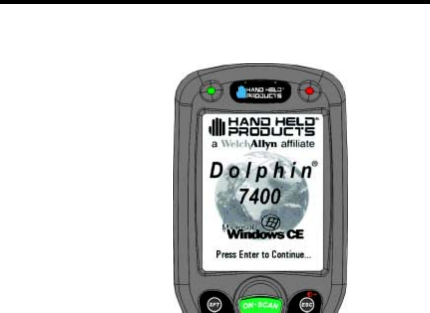
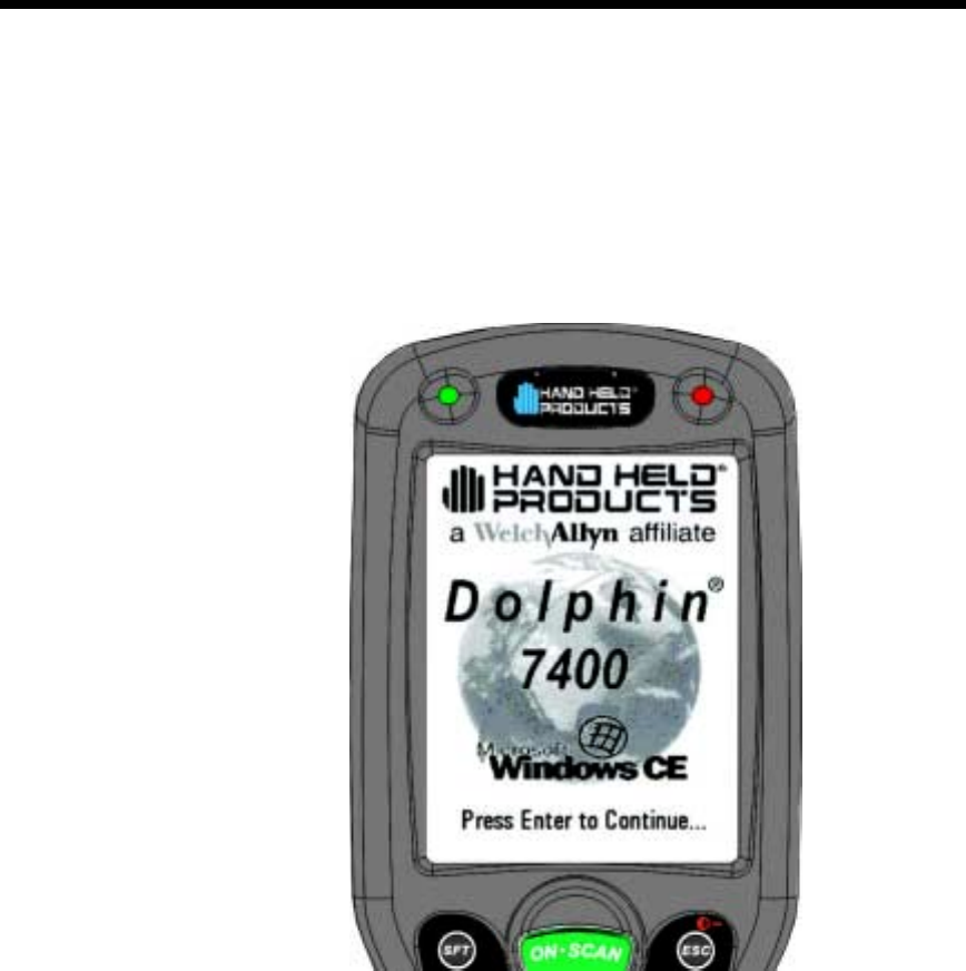
Turning on the Dolphin 7400 for the first time is a cold boot. Follow these steps to
turn on your Dolphin 7400 terminal.
1. Install the charged battery pack in the Dolphin.
2. The red LED will come on and the green LED will blink for approximately three
seconds.
NOTE: DO NOT PRESS ANY KEYS WHILE THE TERMINAL IS BOOTING
UP.
3. The terminal will initialize and after a few seconds will display the Dolphin 7400
splash screen shown below:
17
•
•
•
•
•
•
5-)#2
The Dolphin 7400 terminal is never actually turned off. To conserve power, the
Dolphin suspends operation, or goes into “sleep mode” when it is inactive for a
programmed period of time, as defined by your application. The screen is blank
when the Dolphin is in “sleep mode.” Press the ON/SCAN key to wake the
Dolphin terminal from sleep mode and you can start working where you left off.
The Dolphin terminal also goes into sleep mode if you remove the main battery
pack. To wake the Dolphin terminal from sleep mode, install a charged battery
and press the ON/SCAN key.
WARNING If the main battery and back-up battery are ever fully discharged of power,
the terminal will cold boot. The terminal will be restored to its original state. All data
stored in RAM memory also will be lost.
Dolphin 7400 Splash Screen
18
•
•
•
•
•
•
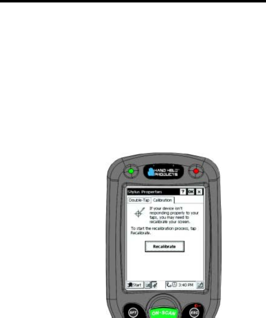
!$).)627
8
$)
If your Dolphin 7400 is equipped with a touchscreen, you need to calibrate the
screen after a cold boot. After the Dolphin 7400 Welcome Splash Screen appears,
you will be prompted to calibrate the screen. Follow the directions on the screen to
calibrate the screen. After calibrating the screen, you will be prompted to set the
date and time on the terminal. The Dolphin 7400 Demo Program main menu
appears after you set the date and time.
Stylus Properties Screen
19
•
•
•
•
•
•
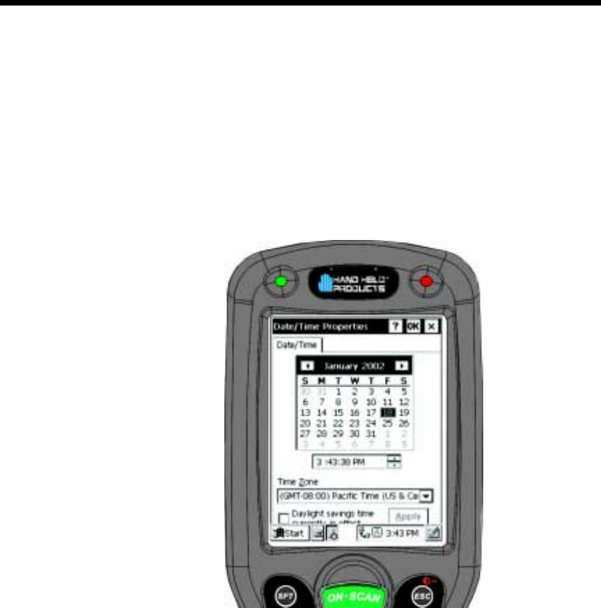
)6
Use the Windows® CE Date/Time function to set the correct date and time for
your Dolphin 7400 terminal. Use the Dolphin 7400 mouse utility to navigate
through the screens if your terminal does not have a touchscreen. For more
information about the mouse utility, see Navigating the Keyboard in Chapter 4.
Note: Exit the mouse utility before adjusting the contrast.
Touchscreen-equipped terminals:
1. From Control Panel, select Date/Time to set the date and time for your termi-
nal.
2. Touch OK to accept the settings and to exit Date/Time. The main screen for
the Dolphin 7400 demo will come up on the screen.
Terminals without touchscreens:
1. Use the Cursor keys to navigate to Date/Time and then press <Enter> to open
Date/Time Properties.
2. Use the Cursor and Tab keys to navigate around the screen and to set the date
and time for your terminal.
3. Press <Enter> to return to the Control Panel.
Date/Time Properties Screen
20
•
•
•
•
•
•
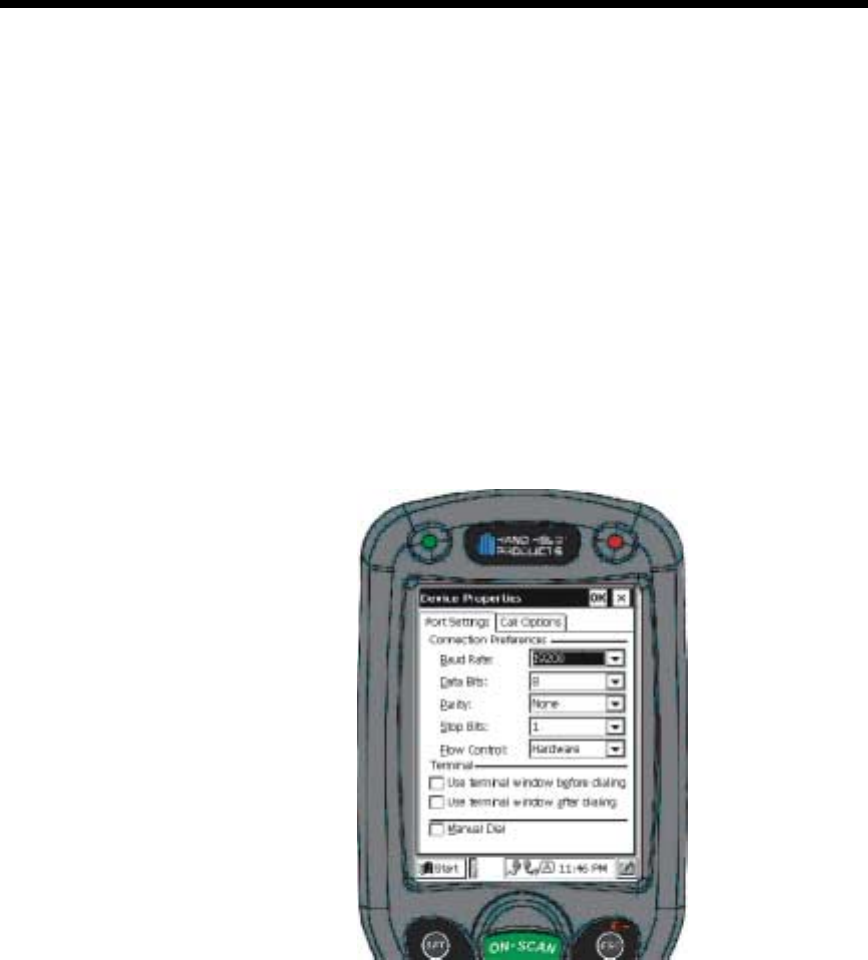
$))2
If your Dolphin 7400 hand held computer is equipped with a modem, follow these
configuration instructions. Use the Dolphin 7400 mouse utility to navigate through
the configuration process if your terminal does not have a touchscreen. For more
information about the mouse utility, see Navigating the Keyboard in Chapter 4.
1. From the Start menu, select Programs>Communication>Remote Networking.
2. Select Make New Connection. Type in name for the connection. Select Dial-
Up Connection and touch Next.
3. Select the modem from the drop-down menu, CIRRUS LOGIC 56K MODEM
and then touch Configure.
4. Set the option on Port Settings tab as shown below and then touch OK.
5. Touch Next and enter the country code, area code and phone number in the
appropriate fields. Touch Finish and the terminal will return to the Connection
window.
For information on using the modem, see Using the Modem in Chapter 4.
'9) !""5-),
After the main battery pack is charged and installed and you have calibrated the
the screen and set the time and date, the Dolphin 7400 terminal is ready to use.
Choose the IMAGE DEMO or SCAN DEMO to verify that the terminal is operating
properly.

21
•
•
•
•
•
•
Touchscreen-equipped terminals:
To take an image:
1. Touch the IMAGE DEMO button.
2. Touch F1 (red key + Q) to view the set-up utility for the IMAGE DEMO.
3. Press <ON/SCAN> button and the image you take will appear on the terminal’s
screen.
4. Touch Back to go back to the main menu of the Dolphin 7400 Demo Program.
5. Press <ESCAPE> to exit the demo.
To scan a bar code label:
1. Touch the SCAN DEMO button.
2. Touch F1 (red key + Q) to view the set-up utility for the SCAN DEMO.
3. Press the <ON/SCAN> button, aim the terminal at a bar code and the red
SCAN LED will illuminate. The green SCAN LED will illuminate and the termi-
nal will beep when a good scan is obtained. Information about the barcode
scanned will appear on the screen.
4. Touch Back to go back to the main menu of the Dolphin 7400 Demo Program.
5. Press <ESCAPE> to exit the demo.
Terminals without touchscreens:
To take an image:
1. Using the Cursor keys, navigate down to the IMAGE DEMO button and press
an <ENTER> key.
2. Touch F1 (red key + Q) to view the set-up utility for the IMAGE DEMO.
3. Press ON/SCAN button and the image you take will appear on the terminal’s
screen.
4. Press <ESCAPE> to go back to the main menu of the Dolphin 7400 Demo Pro-
gram.
To scan a bar code label:
1. Using the Cursor keys, navigate down to the SCAN DEMO button and press
an <ENTER> key.
2. Touch F1 (red key + Q) to view the set-up utility for the SCAN DEMO.
3. Press ON/SCAN button, aim the terminal at a barcode and the red SCAN LED
will illuminate. The green SCAN LED will illuminate and the terminal will beep
when a good scan is obtained. Information about the barcode scanned will
appear on the screen.
4. Press <ESCAPE> to go back to the main menu of the Dolphin 7400 Demo Pro-
gram.

22
•
•
•
•
•
•
)7$8
Under some conditions, you may need to reset the Dolphin 7400 terminal with a
cold boot. These may include:
•
Resetting a locked up operating system or terminal
•
Resetting the terminal back to factory defaults
•
Resetting the terminal after a bootloader, keyboard, and kernel upgrade.
To perform a cold boot:
1. Press and hold the Control (CTRL) and the Escape (ESC) keys for about 10
seconds, then release.
2. Release the keys and the terminal will reset. The red LED will come on and the
green LED will blink for approximately 3 seconds.
3. The terminal will behave as described in the section about Turning the Dolphin
On for the First Time.
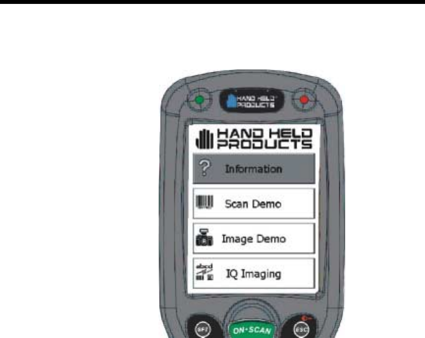
)758
There are times when you may need to warm boot the Dolphin 7400 terminal such
as after loading a software application that requires a warm boot after installing
new software. To warm boot the Dolphin 7400 terminal:
1. Press and hold the Control (CTRL) and the SHIFT (SFT) keys for about 10
seconds, then release.
2. Release the keys and the terminal will reset. The red LED will come on and the
green LED will blink for approximately 3 seconds.
3. The terminal will initialize and after a few seconds will display the main menu
screen for the Dolphin 7400 Demo Program shown below:
23
•
•
•
•
•
•
Dolphin 7400 Demo Program Main Menu Screen

24
•
•
•
•
•
•

25
•
•
•
•
•
•
Dolphin 7400 Overview
System Features
Processor
The Dolphin® 7400/7450 terminal is equipped with a StrongARM™
206MHz RISC microprocessor that runs on a 100 MHz BUS and is
the most powerful Windows® CE platform on the market.
Operating System
Microsoft® Windows® CE is a compact, highly efficient, scalable
operating system. Its open architecture and minimal memory
requirements facilitates development of applications for energy-
efficient data collection devices like the Dolphin 7400/7450 terminal.
The graphical interface also makes the device more user-friendly.
Memory
Main Board
The memory configuration for the Dolphin 7400/7450 terminal is
32MB RAM and 32 MB FLASH.
Compact Flash Card
The Dolphin 7400/7450 terminal has one Type I compact flash card
socket for additional application and data storage capacity. Additional
modular compact flash upgrades of 64 MB, 128 MB, and 256 MB are
available through an authorized Hand Held Products service center.
The compact flash card socket is not user accessible to preserve the
Dolphin 7400/7450 terminal’s environmental rating.
Radio options
The Dolphin 7400/7450 terminal has one Type II PCMCIA card slot to
allow for an interface with 2.4 GHz 802.11b Direct Sequence radio
networks and Wi-Fi™ certified products. Radio options currently
available include the Cisco® 342 (FCC #LDK102035) and Cisco®
352 (FCC #HD5-7400-352) series network cards.
3
26
•
•
•
•
•
•
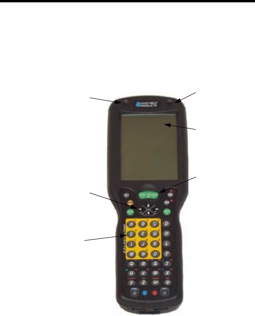
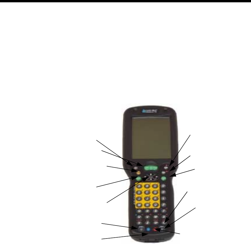
#,#
This section describes features on the Dolphin 7400 terminal front panel.
1
The red light emitting diode (LED) located at the upper right corner of the LCD
display is SCAN LED. This LED illuminates when the user presses the ON/SCAN
key and activates the scan engine. The green LED located at the upper left corner
of the LCD display is DECODE LED. This LED illuminates when the bar code
software successfully decodes a bar code. Both LEDs are software
programmable.
Decode LED Scan LED
1/4 VGA Display
(Optional
Touchscreen)
Cursor Key
ON/SCAN Key
Keypad with
epoxy-coated keys

27
•
•
•
•
•
•
46!9:*
The Dolphin 7400 screen is a 240 x 320 pixel 1/4 VGA display. The
electroluminescent backlight allows you to view the display in low light conditions.
To conserve power, the backlight may be programmed to automatically turn off
after a prescribed amount of time. The contrast may be adjusted with the contrast
keys.
The Dolphin 7400 display may be equipped with a touchscreen that can be
activated with a stylus or finger.
0;6$*;<
The ON/SCAN key is centrally located for easy use with the right or the left hand.
$<
The centrally located cursor key allows full Windows® navigation.
*)
The Dolphin 7400 terminal has an internal speaker that sounds audio signals as
you scan bar code labels and enter data. Signals are emitted at a sound level of
80 dB sound pressure level at two feet. The operating frequency range is 500 Hz
up to 8 kHz. The speaker can also be used for playing sounds using WAV files.
<
The Dolphin 7400 terminal’s keyboard features epoxy-coated keys and is backlit
for easy use in dark and dim lighting conditions. The keyboard’s yellow
background enhances the readability of the numeric keys. The centrally located
ON/SCAN key and other important keys allow for easy imaging, bar code
scanning and application navigation. All keyboard versions are suited for right-
handed and left-handed use.
28
•
•
•
•
•
•
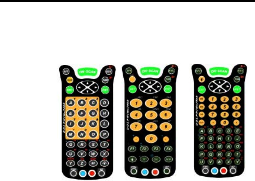
There are three keyboard options for the Dolphin 7400:
•
43-key alphanumeric
•
35-key numeric/alpha only
•
56-key alphanumeric
#*
The Dolphin 7400 RF terminal’s antenna is a unity gain, quarter-wave, monopole
antenna.
43-key
alpha/numeric keyboard 35-key numeric/alpha
keyboard
56-key
alpha/numeric
keyboard
29
•
•
•
•
•
•
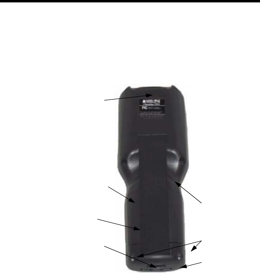
-,#
This section describes features on the Dolphin 7400 back panel. All versions of
the 7400 terminal have similar back panels except for the safety labels specific to
how the the terminal is equipped.
))1)
Dolphin 7400 terminals are equipped with an imaging engine that reads and
decodes linear, stacked linear (PDF417) and 2D matrix bar code symbologies.
With the latest CMOS-based technology, the engine works like a digital camera
and adds functionality and value to the Dolphin 7400 by adding additional
capabilities, such as digital image capture, signature capture and reading OCR
characters. Digital images taken with the 7400 terminal have a maximum image
size of 640 x 480 pixels and may have up to a 256 gray scale image definition.
Files formats supported image storage include Bitmap (bmp), JPEG (jpg) and
Portable Network Graphics (png).
A clear window with anti-reflective, scratch-proof coating covers the imaging
engine to protect it from dust and dirt.
Battery Well
Battery
RS-232 Port
IrDA Port
Hand Strap
Battery Charging
Contacts
Image Engine

30
•
•
•
•
•
•
5
The Battery well is a recessed area on the back of the Dolphin that holds the 2700
mAh NiMH battery pack.
/
The integrated elastic hand strap provides the user with a comfortable, secure
grip on the terminal. If desired, the strap may be removed.
$))$
When the Dolphin is placed in the main well of the Dolphin HomeBase, the
Dolphin’s battery pack is charged through these gold-plated contacts.
$
2=>=(&(,
The industry-standard RS-232 port allows the user to connect with peripherals,
such as printers, serial modems and desktop computers for serial communication
to the Dolphin 7400 terminal. The maximum speed is 115kbps with seven baud
rate settings.
*,
The IrDA (Infrared Communications) Port allows the Dolphin to communicate
through the Dolphin HomeBase/IntelliBase to a host serial device. The maximum
speed is 115kbps.
,?-
The optional phone jack is located on the back of Dolphin 7400 terminals
equipped with a low power, high speed, V.90 56K FAX/modem to allow
communications via an analog phone line.
,%
'9$,
This port connects the Dolphin 7400 to DC power for powering peripheral devices
and charging the main and backup batteries.
Power is fed through the RS-232 communications port.
CAUTION: Use only the 3.6V battery packs provided by Hand Held Products. The
use of any other battery pack in the Dolphin 7400 terminal will void your warranty
and may result in damage to the Dolphin terminal or battery.

31
•
•
•
•
•
•
There are two batteries in the Dolphin:
Internal NiMH Backup Battery Located inside the Dolphin, this battery backs
up the RAM and clock when the NiMH main battery is discharged or removed
from the terminal. The internal backup battery is not user replaceable.
NiMH Battery Pack The battery pack is the primary power source for operating
the Dolphin terminal.
;/2-
The Dolphin’s internal backup battery prevents the terminal from being reset if you
need to remove and replace the main battery pack. The battery retains RAM data
and allows the real-time clock to remain operational for up to 30 minutes when the
battery pack is removed. For the initial charging cycle, it is recommended that the
terminal be charged for approximately 8 hours to allow adequate charging time for
the back-up battery. Not doing so may result in the terminal becoming unstable
should the unit lose power and the backup battery is required.
If the backup battery becomes discharged of power after the initial charge cycle, it
will require a minimum of 5 hours of charging time to perform and maintain the
system as described above.
The internal backup battery is charged by the Dolphin’s main battery pack. If the
terminal is left without the main battery pack for more than 30 minutes, the internal
backup battery needs to be recharged.
Note: Data and programs stored in FLASH remain safe even if the internal backup
battery fails. However, you must reset the real-time clock using the Windows CE
Time and Date function.
Follow these guidelines to maximize the life of the Dolphin’s backup battery:
•
Keep a charged NiMH battery pack in the Dolphin. The internal battery will prematurely
discharge if there is not at least a partially charged battery in the terminal.
•
Put the Dolphin in the HomeBase when the terminal is not in use.
2,-
The 3.6V, 2700 mAh Nickel-Metal-Hydride (NiMH) battery pack is the primary
power source for the Dolphin. Other NiMH batteries may be approved by Hand
Held Products to work with your Dolphin. Contact Hand Held for more
information.
The 2700 mAh NiMH battery is designed to operate in a temperature range of -10
to 50 °C (14 to 122° F). For maximum performance, charge the batteries between
10 and 35 °C (50 and 95° F).
2)),%
Data and files saved on the Dolphin 7400 terminal may be stored in RAM so it is
important for you to maintain a continuous power supply to the terminal. When the
main battery pack becomes low, the Low Battery Charge icon will appear in the
notification tray at the bottom of the screen. The Critical icon will appear when the
battery is critically low. There is also a Low Battery icon that will appear when the
back-up battery is low.

32
•
•
•
•
•
•
Letting the back-up battery become fully discharged will cause you to lose all
data. Therefore, you should keep a charged battery pack in the Dolphin at all
times to conserve the internal back-up battery. When you remove a battery pack,
insert another charged pack in the Dolphin. The internal battery will prematurely
discharge if there is not at least a partially charged battery in the terminal.
A battery status indicator will display in the notification tray when the battery is low
or critically low. If there is no indicator, the battery is adequately charged.
If the main battery is low and the terminal is in sleep mode, pressing the ON/
SCAN button will not wake up the Dolphin terminal; you must replace the spent
pack with a fully charged battery.
3),%$,
The Power control panel displays information about current battery status and
allows you to set options that can conserve battery power.
There is also a battery usage indicator displayed. This indicator represents the
total cumulative time that the current main battery pack has been in use. If the
main battery is replaced with a different battery pack, the indicator will reset to
0:00. (If the main battery is removed and then the same battery placed back into
the terminal, the counter will not reset as it is tracking cumulative time on a
particular battery - each battery is uniquely identified by a serial number). Also, if
the terminal is placed in a HomeBase and is running on external power, the
indicator will cease counting. When the terminal is removed from the HomeBase,
the timer will resume.
To open the Power control panel:
Touchscreen-equipped terminals:
1. Tap the Start button, tap Settings, and then tap Power. If the power plug icon is on the
task bar, double-tap it.
2. Tap the Battery or Power Off tab.
3. Select your preferences. For more information, read the following paragraphs, or tap the
Help button in the upper right corner of the screen.
4. Tap OK to save the changes and exit or tap the Close (X) button in the upper right cor-
ner to exit without saving the changes.
Non-touchscreen terminals:
1. Use the cursor keys to navigate to the last program icon on the desktop.
2. Press the Tab and then the Enter key to open the Start menu.
3. Use the cursor keys to navigate to the Settings menu and then press Enter.
4. Press Enter again to select the Control Panel.
5. Use the Cursor keys to navigate to Power and then press Enter to open Power Proper-
ties.
6. Use the Cursor and Tab keys to navigate between the Battery and Power Off tabs and
to select your preferences.
7. Press Enter to return to the Control Panel.
8. Press ALT to open the File menu and use the Cursor key to navigate to Close.
9. Press Enter to close the Control Panel.
33
•
•
•
•
•
•
+),-
For maximum battery life, you must service, or deep cycle, the battery twice
before initial use. It is also recommended that you service the battery once per
month. To deep cycle, insert the battery into the Dolphin 7400 QuadCharger or
use the Battery Conditioning Utility.
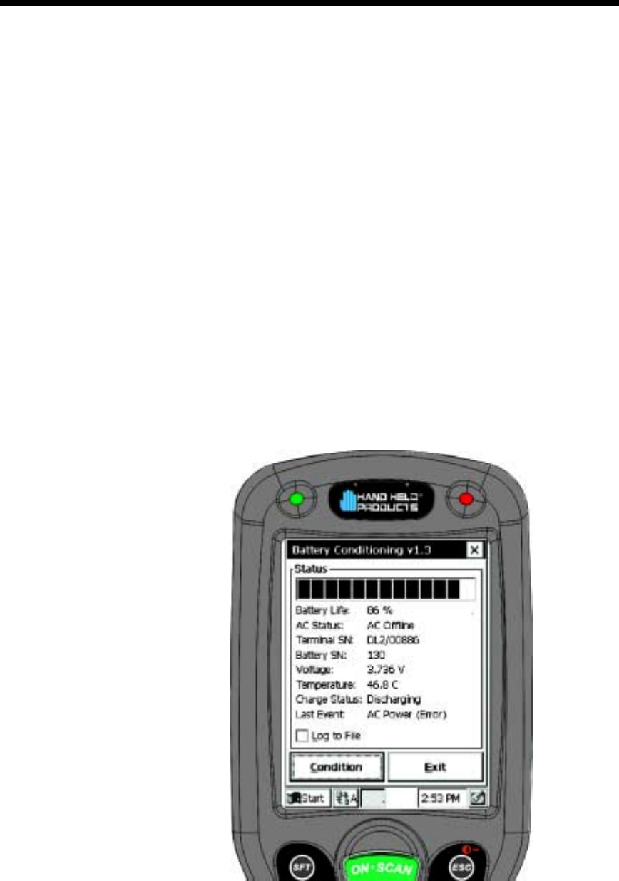
The Battery Conditioning Utility is used to condition or deep cycle a battery in the
Dolphin 7400 terminal. The discharge/charge cycle will minimize battery memory
effects and ensure the battery data is correct. A complete discharge/charge cycle
may take up to 15 hours for a fully charged battery. The actual cycle time will vary
depending on the battery state when the cycle was initiated.
Follow these instructions to use the Battery Conditioning Utility to deep cycle the
battery before initial use:
1. Put the battery pack in the Dolphin terminal.
2. Connect the Dolphin 7400 terminal to external power. After starting the Battery Condi-
tioning Utility, it will indicate an error, as shown below, if the terminal is not on AC
power.
3. Select Start>Programs>HHP>BattCondition to start the Battery Condition Utility.
Battery Conditioning Utility AC Power Error

34
•
•
•
•
•
•
4. Touch the ‘Condition’ button (or the ‘C’ key on non-touchscreen terminals) to start the
battery conditioning process. The process will begin in approximately 60 seconds.
5. Touch the ‘Abort’ button (or the ‘A’ key on non-touchscreen terminals) to abort the bat-
tery conditioning process.
For more information on using the Quad Battery Charger, see the Quad Battery
Charger User’s Guide.
$)),-
You can charge the Dolphin’s main battery pack with one of the following
methods:
•
Placing the battery pack in the Dolphin 7400 terminal and then placing the terminal in the
terminal well of the Dolphin HomeBase.
•
Placing the battery pack in the Dolphin 7400 Quad Battery Charger.
)
To maintain top performance from batteries, follow the guidelines below when
storing them:
Avoid storing batteries outside of the specified range of -4 to 104° F (-20 to 40°C)
or in extremely high humidity.
For prolonged storage, do not keep batteries stored in a charger that is connected
to a power source.
During long-term storage, battery deactivation may tend to occur which may
cause charging to stop early during recharging after storage. This issue can be
handled by charging and discharging the battery several times. Also, the first
charging after prolonged storage may yield a lower than normal capacity. While
this will vary depending on the storage conditions, charging and discharging the
battery several times will almost completely restore capacity.

35
•
•
•
•
•
•
/HDUQLQJWR2SHUDWH'ROSKLQ
1)
Data can be entered into the Dolphin 7400 in a variety of ways,
including the optional touchscreen, keyboard, image engine, via radio
or the optional modem.
9
If equipped, you can use the Dolphin 7400 terminal’s touchscreen to
operate the terminal and enter data.
To enter data, use a stylus to select menu options, functions, etc.
Note: For touchscreen input, only use a stylus or your finger. Use of other
objects, such as paper clips, pencils, ink pens can damage the
touchscreen and will void the warranty.
9<
Data can be entered into the Dolphin 7400 terminal via the keyboard.
The Dolphin 7400 has three keyboard options: 43-key alpha/
numeric, 35-key numeric/alpha, and 56-key full alpha/numeric.
To enter data, press the appropriate key and the corresponding
number or letter appears on the screen.
See Appendix A for a list of keyboard shortcuts for navigating the
keyboard.
A mouse utility is also available to help with navigating around the
Dolphin 7400 terminal screen.*
* Exit the mouse utility prior to adjusting the contrast.
3))
Dolphin 7400 terminals equipped an image reader can read 1D and
2D bar codes, OCR characters and capture images, such as
signatures.
The imager has a viewfinder that projects a bright red aiming beam.
Center the aiming beam over the bar code for the best read though a
good read can be obtained from most any position.

36
•
•
•
•
•
•
$
$2
Via the RS232 Port
The industry-standard RS-232 port supplies 5 volts of power and allows the user
to connect external scanners and printers to the Dolphin 7400 terminal.
Via the IrDA Port
The IrDA port allows the Dolphin 7400 to send data via pulses of light to and from
other IrDA-compliant devices, such as printers and PCs.
Via the Radio
The Dolphin 7400 RF is equipped with a 2.4 GHz 802.11b-compliant direct
sequence spread-spectrum local area network (LAN) radio.
Via the Modem
The Dolphin 7400 may be equipped with a low power, high speed, V.90 56K FAX/
modem to allow communications via an analog phone line.
%$,)
Microsoft® ActiveSync®
In the Dolphin 7400 development environment, Microsoft® ActiveSync® is a tool
for developers. It allows CE devices like the 7400 to connect to and exchange
data with a desktop computer.
RAS
Short for Remote Access Services, a feature built into Windows NT® that enables
users to log into an NT-based LAN using a modem, X.25 connection or WAN link.
RAS is fully supported and allows the use of PPP or SLIP connections for network
connectivity.
37
•
•
•
•
•
•
3)<
3)<
The Dolphin 7400’s keyboard has special keys and key combinations that you use
to type characters or perform functions. See the chart in Appendix A for key
combinations for keyboard functions and special characters that use these keys.
Dolphin 7400 43-Key Front View
ON/Scan Key
Escape Key
Enter Key
Backlight Key
Alt Key
Modifier Key
Number Lock
Key
Shift Key
Cursor Keys
Control Key
Tab Key
Enter Key
Modifier Key
38
•
•
•
•
•
•
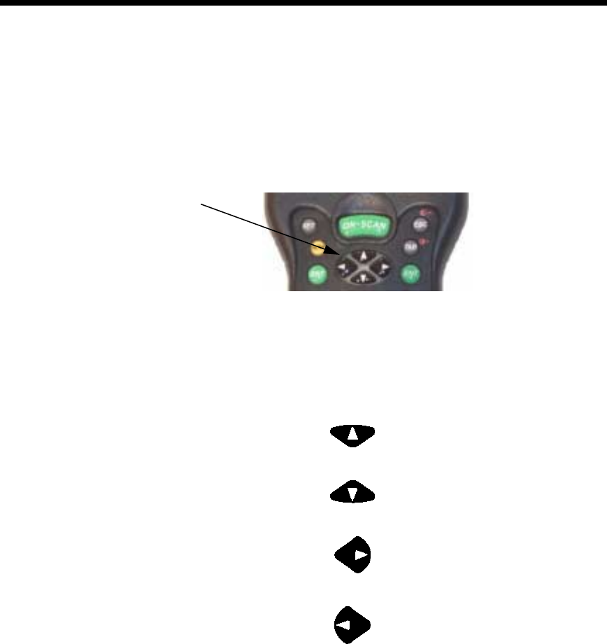
Cursor Keys
3)$<
Use the cursor keys to navigate around on an application screen. The use of
these keys can vary depending on the application.
Cursor Keys
To Use This Cursor Key Press Description
Arrow up Moves cursor up one row
or line.
Arrow down Moves cursor down one
row or line.
Arrow right Moves cursor one
character to the right.
Arrow left Moves cursor one
character to the left.

39
•
•
•
•
•
•
3)2<
All three versions of the Dolphin 7400’s keyboard feature the standard Windows
modifier keys, Alt, Ctl and Shift. For single-handed operation, the Shift key only
modifies the next key pressed; it must be pressed and released before each key
you wish to make lower case. For multiple lower case characters, hold the Shift
key down with one hand while typing with the other. Functions of the Alt and Ctl
keys are dependent on the software application in use.
There are two additional modifier keys located on the bottom row of the keyboard.
Use these keys in combination with other keys to type the corresponding color-
coded characters and functions. The Red and Blue keys only modify the next key
pressed; these keys must be pressed and released before each key you wish to
modify to the Blue or Red case. See the chart in Appendix A for key combinations
for keyboard functions and special characters that use these keys.
0<
ON/SCAN Key
The ON/SCAN key “wakes” the terminal from sleep mode. Its position also allows
convenient one-handed image-taking and/or barcode scanning.
Shift (SFT)
The Shift key toggles the keyboard from upper case alphabet mode to lower case
alphabet mode and back. Caps Lock may also be toggled by: pressing the red
modifier key followed by the Shift key or double-tapping the Shift key. When Caps
Lock is toggled off, the Shift key makes characters upper case; when it is toggled
on, the Shift key makes keys lower case.
Enter (ENT)
The Enter key confirms data entry.
Escape (ESC)
The Escape key performs a cancel action.
Tab
The Tab key moves the cursor to the next tab stop or the next control on a form.
Modifier Keys

40
•
•
•
•
•
•
Light
The Light key toggles the LCD and keyboard backlights on and off.
Number Lock (NUM)
This key is included only on the 43-key keyboard option which defaults to
alphabetic mode. The Number Lock key toggles between the alphabetic and
numeric modes.
Alpha Lock (ALPHA)
This key is included only on the 35-key keyboard option which defaults to numeric
mode. The Alpha key toggles between the numeric and alphabetic modes.
Backspace (BKSP)
This key appears on both the 35 and 56-keyboard options. The Backspace key
moves the cursor back one space for each time the key is pressed. Backspace is
a shifted function on the 43-key keyboard version. To delete a single character,
press Red key + SP. To delete multiple characters, press Red key + SP and hold
down the SP key.
Delete (DEL)
This key appears on both the 35 and 56-keyboard options. The Delete key deletes
one character for each time the key is pressed. Delete is a shifted function on the
43-key keyboard version.
<$
There are some keyboard functions and special characters not defined on the
Dolphin 7400 keyboard. See the charts in Appendix A for the key combinations
used to access these functions and special characters on your terminal.
41
•
•
•
•
•
•
;+))<
The Dolphin 7400 terminal has a mouse utility to simplify navigating around the
screen, especially for non-touchscreen equipped terminals.
Note: Exit the mouse utility prior to adjusting the contrast.
To activate the mouse utility at any time in any window, double-tap the blue
modifier key and the mouse pointer will appear in the middle of the screen as
shown in the screen shot below. To deactivate the mouse, double-tap the blue
modifier key again and the mouse pointer will disappear.
Use the cursor keys to navigate around the screen. For a left mouse click, press
either one of the ENT keys. Use a left mouse click to select an item or launch a
program.For a right mouse click, use the TAB key . When you use a right mouse
click, a menu of items pops up and tells you what actions you can perform, and
shows you shortcuts. To open files or applications with a double click, tap the ENT
key twice in rapid succession.
In mouse mode, you can also scroll the active window for dialog boxes that are
not formatted for the 1/4 VGA display. Move the cursor to one of the four screen
edges and continue to hold down the arrow key to initiate the scrolling feature.

42
•
•
•
•
•
•
To adjust the double-click speed for the mouse utility, go to Control
Panel>Settings>Stylus. Follow the directions on the Double-Tap tab to adjust the
settings. Note: The Double-Tap setting for the stylus also applies to the mouse.

43
•
•
•
•
•
•
3)2
If your Dolphin 7400 is equipped with the optional integrated modem, you can
allow communications via an analog phone line for dial-up applications. A phone
jack is built into the back of the Dolphin 7400.
To communicate via the modem, remove the rubber plug from the phone jack and
plug in the analog phone line. Note: The rubber plug should be inserted in the
phone jack when it is not in use to protect the integrity of the connector.
If you have not already configured the modem, refer to Configuring the Modem in
Chapter 2.
To make a connection:
1. From the Control Panel, select Start>Programs>Communication>Remote Networking.
2. Enter your User Name and Password.
3. Touch Dial Properties and select Tone Dialing. Note: Check Dialing Patterns and edit,
if necessary, ie, if 9 or the area code must be dialed with local calls.
4. Touch Connect.
Phone Jack on rear of Dolphin 7400
Phone Jack

44
•
•
•
•
•
•

45
•
•
•
•
•
•
'ROSKLQ5)7HUPLQDO
The Dolphin 7400 RF terminal integrates the basic functionality of
the Batch terminal with a radio frequency interface that allows the
terminal to communicate with a host computer via a wireless local
area network (WLAN).
The Dolphin 7400 terminal has one PCMCIA Type II integrated card
slot to allow for an interface with 2.4 GHz 802.11b Direct Sequence
radio networks and other WiFi® certified products . The radio uses
direct sequence spread spectrum (DSSS) technology, which spreads
its signal continuously over a wide frequency band, and provides an
Ethernet-like data rate of up to 11 megabits per second. The radio
may also provide up to 128-bit Wired Equivalent Privacy (WEP)
encryption. WEP is used to encrypt and decrypt data signals
transmitted between Wireless LAN (WLAN) devices. It is an optional
security encryption mechanism defined within the 802.11 standard
that makes a wireless LAN link as secure as a traditional wired link.
The optional WEP security mechanism is available with 128-bit or 40-
bit encryption.
Dolphin 7400 RF is interoperable with other 802.11b WiFi®-compliant
products to allow network expansion as needed. It can be connected
to other devices, such as printers and PCs via PC-card adapters.
Refer to Chapters 1 and 2 in this manual for more on basic operation
of the Dolphin terminal.
46
•
•
•
•
•
•
$)) !""#
When you cold-boot the Dolphin 7400 RF terminal, the red LED comes on and
green LED blinks and after approximately 3 seconds, the Dolphin 7400 welcome
screen shown below will appear.
Dolphin 7400 Welcome Screen
47
•
•
•
•
•
•
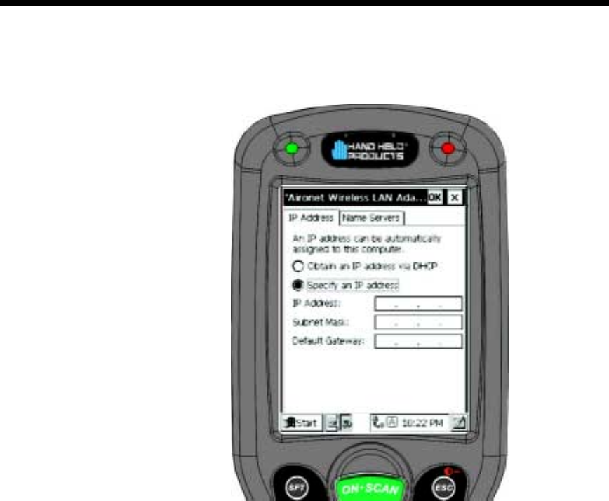
Touch <Enter> and the screen below will show on the terminal:
After obtaining an IP address via DHCP or specifying the terminal’s IP address,
you will be prompted to calibrate the touchscreen and then to set the date and
time. Follow the directions on the screen to complete these tasks. For more
information, see Chapter 2, Getting Started.
$3 !""@"(A44
The following utilities are available for configuring your Dolphin 7400 terminal
802.11b radio:
Aironet Client Utility (ACU) - Configures the radio for use in a wireless network
Client Encryption Manager (CEM) - Configures a Wired Equivalent Privacy (WEP)
key for the radio
Cisco Link Status (CLS) - Enables you to view the current status of your client
adapter
Client Statistics Utility (CSU) - Enables you to view statistics that indicate how data
is being received and transmitted by your client adapter
This document covers the basics of the Aironet Client Utility (ACU). For more
detailed information on these and the other utilities, please refer to the following
Aironet Wireless LAN Adapter Screen
48
•
•
•
•
•
•
documents at www.cisco.com, “Overview of the Client Utilities for Windows CE”
and “Using the Client Utilities for Windows CE”.
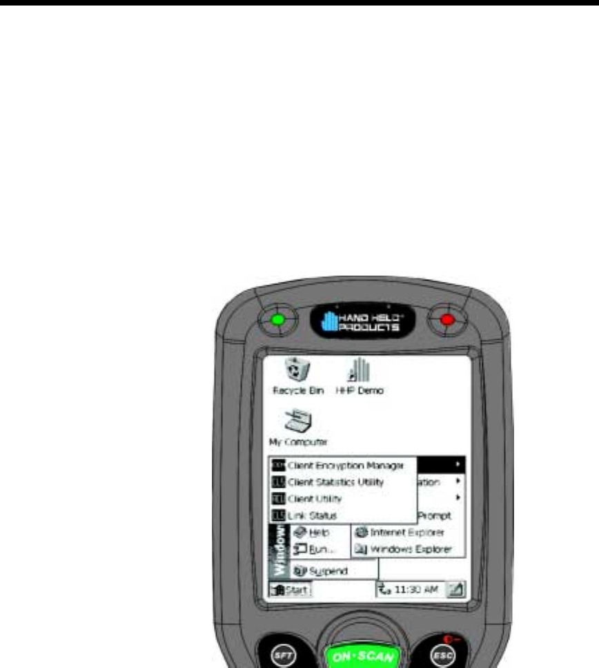
$))
To configure the radio for use in the wireless network, select
Start>Programs>Cisco>Client Utility. The Aironet Client Utility (ACU) enables you
to change the configuration parameters of the Dolphin 7400 terminal 802.11b
radio.
Cisco Client Utilities
49
•
•
•
•
•
•
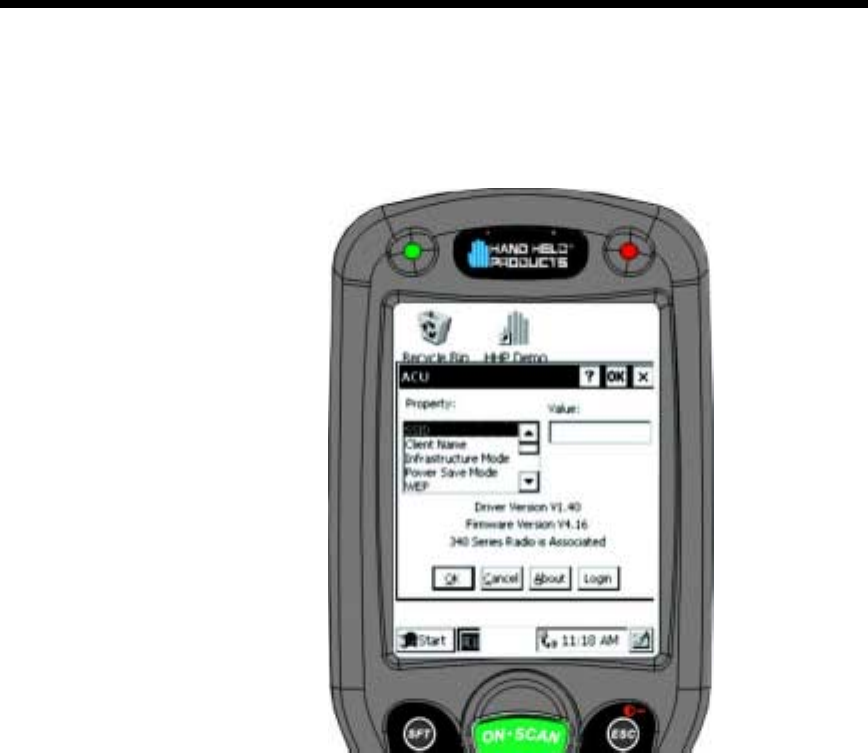
In the Aironet Client Utility (ACU) dialog box shown below, enter the radio specific
information for your Dolphin 7400 terminal. When finished, touch OK at the bottom
of the ACU screen to save any changes you have made.
For more information on specific radio settings for the Cisco Aironet Client
Utilities, go to www.cisco.com and retrieve the document called “Using the Client
Utilities for Windows CE.”
/$+
Hand Held Products offers several host connectivity options for Dolphin 7400 RF
wireless LAN solutions. Direct Connect TN Client software is a thick-client solution
that connects Dolphin 7400 RF computers directly to host applications via
TN3270, TN5250 or TNVT terminal emulation using industry-standard TCP/IP
protocol. Another option is a three-tier client server solution, or thin-client
implementation, for 3270, 5250 and VT100/220 terminal emulation that uses a
Universal Gateway. The Gateway establishes communication to a host such as
an AS400 and maintains communication to both the Dolphin 7400 RF terminal
and the host.
-=$1
PowerNet TN Client (telnet client) software allows the Dolphin 7400 RF terminal to
communicate directly with applications running on AS/400, ES/9000, HP/6000 or
other hosts connected to an Ethernet backbone and that support TCP/IP. The
TNVT, TN3270, and TN5250 emulations use TCP/IP to communicate from the
Aironet Client Utility Screen

50
•
•
•
•
•
•
Dolphin 7400 RF terminal through the access point to the host. There is no
network controller or server.
=$1
Hand Held Products’ thin-client terminal emulation solution uses a Universal
Gateway to provide host connectivity. The Universal Gateway connects to the
hosts such as AS/400, ES/9000 and HP/6000 via Ethernet and communicates to
the application via Ethernet for 3270, 5250 or telnet for DEC VT220 terminal
emulation environments.
See Chapter 10 of the PowerNet Twin Client Reference Manual for more on the
overlays for the Dolphin 7400.

51
•
•
•
•
•
•
/
As the hub of your Dolphin system, the HomeBase/IntelliBase/USB
HomeBase performs three important functions – power conditioning,
communications and storage. Three versions of the charging/
communications cradle are available:
•HomeBase
for communicating with PC-based equipment using a
half duplex serial mode
•IntelliBase
for communicating with devices such as printers and
modems without integrated IrDA protocol software
•USB HomeBase
for communicating directly with a USB-
compatible host computer
,%$)
The HomeBase/IntelliBase/USB HomeBase provides power to the
Dolphin terminal to enable the terminal to charge its battery.
6*0$
The infrared, or Ir communications port, on the HomeBase/IntelliBase
connects with the IrDA port on the Dolphin terminal. With no pins or
contacts to break, Ir will work reliably for years. Reliable data
communications at speeds of up to 115k baud can be transmitted by
the HomeBase/IntelliBase; data transmission rates with the USB
HomeBase are up to 4Mbps are possible but, at this time, are limited
to 115 kbps as the Dolphin 7400 does not currently support 4 Mbps
data transfer.
The IntelliBase infrared connection to the terminal uses IrDA-
compliant hardware and software for a standard reliable connection.
Communications between the HomeBase and other devices occur a
half duplex serial mode. Half duplex refers to the transmission of data
in just one direction at a time.
The USB HomeBase enables direct communication with USB-
compatible host computers at rates of up 115 kbps. The USB
HomeBase also is IrDA 1.3 compliant.
The HomeBase/IntelliBase/USB HomeBase cannot be “daisy-
chained”.
$+)
The HomeBase/Intellibase/USB HomeBase is a safe and convenient
storage receptacle for the Dolphin terminal.
52
•
•
•
•
•
•
/663/,#
#,
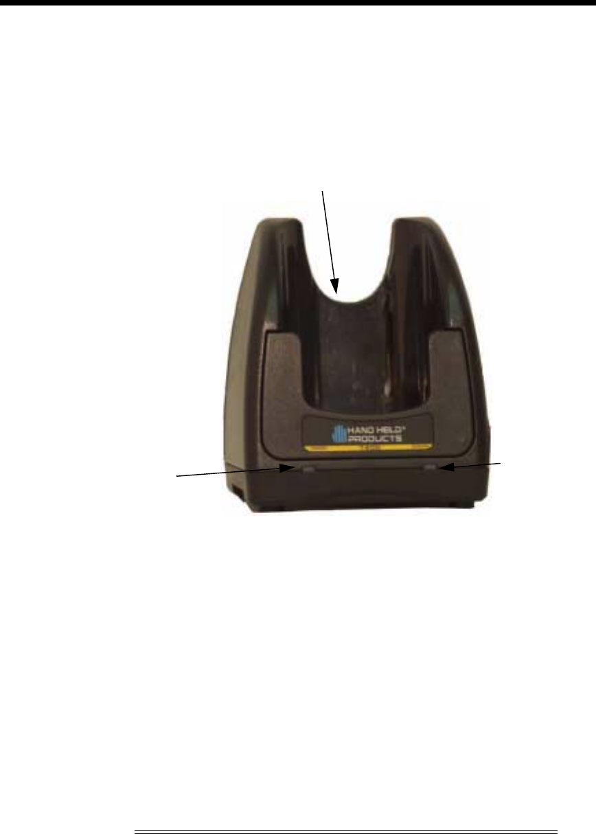
The front panel of the HomeBase/IntelliBase/USB HomeBase has one slot:
Dolphin Terminal Well Place the Dolphin in this well to communicate with a host
device and to charge the Dolphin’s battery.
LEDs There are two LEDs on the front panel of the HomeBase/IntelliBase/USB
HomeBase
1. Dock LED Turns solid green when the Dolphin Terminal is properly seated into the
Dolphin HomeBase.
2. COMM LED Indicates the status of data transfer between the Host Device and the
Dolphin Terminal as described below:
Front View of HomeBase/IntelliBase/USB HomeBase
Comm LED Description
Red LED
Data is being sent from the Host Device to the
Dolphin
HomeBase.
Green LED
Data is being sent from the Dolphin HomeBase
to the Host Device.
Orange LED
Data is being sent at high data rates.
DOCK
LED
COMM
LED
Terminal Well
53
•
•
•
•
•
•
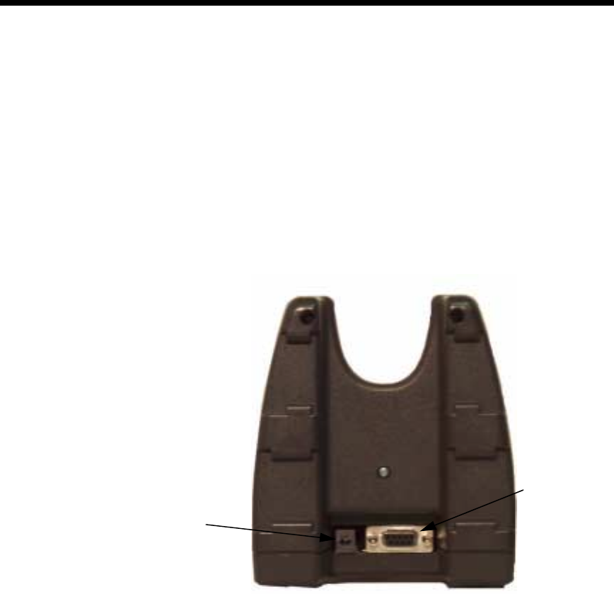
-,
/6
I
There is a 5V DC power supply connector and an RS-232 connector:
Power supply connector Use this connector to attach a power supply to the
HomeBase. The power supply provides 5V DC input for communications and
battery charging.
RS-232 Communications Port Use a standard serial cable to connect this port to a
host RS-232 device.
Rear View of Dolphin HomeBase/IntelliBase
Power Supply
Connector
RS-232
Connector
54
•
•
•
•
•
•
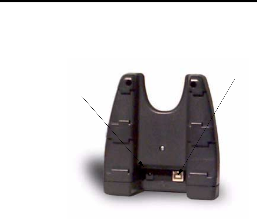
3/
There is a 5V DC power supply connector and a USB connector:
Power supply connector Use this connector to attach a power supply to the
HomeBase. The power supply provides 5V DC input for communications and
battery charging.
USB Communications Port Use a USB full-speed detachable cable to connect this
downstream device port to an upstream USB Host or Hub. The USB HomeBase is
USB 1.3 compliant.
Rear View of Dolphin USB HomeBase
Power Supply
Connector
USB
Connector
55
•
•
•
•
•
•
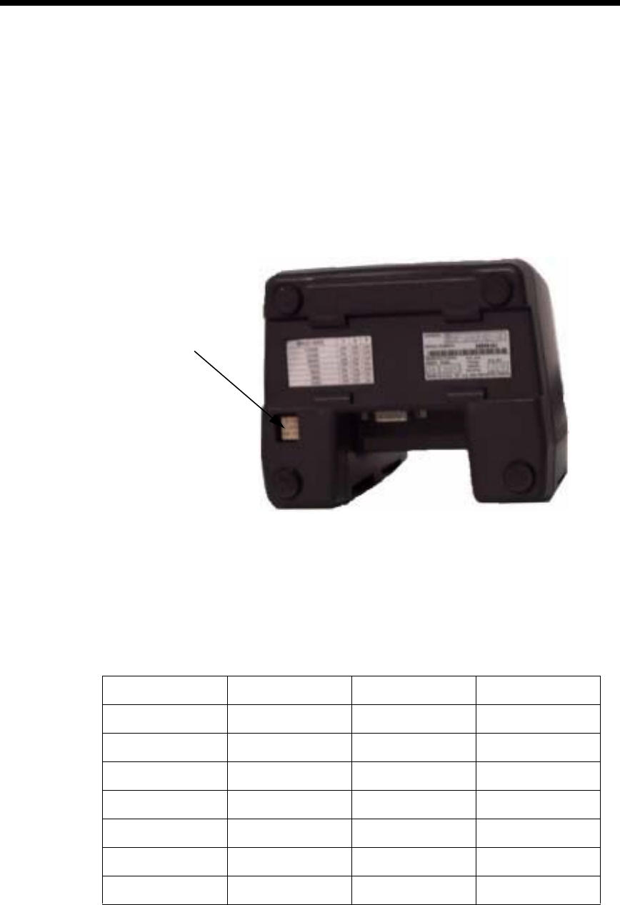
,/6
A Baud Rate switch used to select the communication baud rate is located on the
bottom of the HomeBase/IntelliBase. The Baud Rate Switch on the the
HomeBase is a three-position switch; four-position on the IntelliBase. Switch
position and the corresponding baud rates are shown in the chart below.
The USB HomeBase does not require a baud rate switch.
Bottom View of HomeBase/IntelliBase
Baud Rate Switch 1 Switch 2 Switch 3
115200 OFF OFF OFF
57600 ON OFF OFF
38400 OFF OFF ON
19200 OFF ON OFF
9600ONONOFF
4800 ON OFF ON
2400 OFF ON ON
Baud Rate
Switch

56
•
•
•
•
•
•
,%)
When seated in the HomeBase/IntelliBase/USB HomeBase, the Dolphin terminal
receives the power it needs to charge the battery and to run its internal circuitry.
The Dolphin terminal can be stored indefinitely in the HomeBase/IntelliBase/USB
HomeBase without damage to the terminal or the HomeBase/IntelliBase/USB
HomeBase. Keep the HomeBase/IntelliBase/USB HomeBase plugged in so that
the Dolphin terminal battery pack stays fully charged.
$))*
The HomeBase/IntelliBase/USB HomeBase supplies charging power to the
Dolphin terminal so that the terminal can monitor the charging of its battery pack.
This charging method protects the battery from being damaged by overcharging.
Therefore, the Dolphin terminal may be stored indefinitely in the HomeBase/
IntelliBase/USB HomeBase without damage to the terminal, the battery pack, or
the HomeBase/IntelliBase/USB HomeBase.
To charge a Dolphin terminal, follow these steps:
1. Insert a battery pack into the Dolphin terminal.
2. Place the terminal, imager/laser engine window up and the LCD visible, in the Terminal
Well of the HomeBase/IntelliBase/USB HomeBase.
3. Let it glide down into the well until it stops.
4. Once the Dolphin terminal is properly seated, the Dock LED on the
HomeBase/IntelliBase/USB HomeBase will be solid GREEN.
=$)
For maximum battery life, Hand Held Products recommends that you deep-cycle
(service) the battery twice before initial use and then, once a month thereafter.
Since the Dolphin 7400 HomeBase/Intellibase/USB HomeBase do not have deep-
cycling capabilities, it is recommended that you use the Battery Conditioning
Utility software or Dolphin 7400 Quad Battery Charger. See the Battery
Management section in Chapter 3 for more information.
Baud Rate Switch 1 Switch 2 Switch 3 Switch 4
OFFONONN/A
ON OFF OFF N/A
ON OFF ON N/A
ON ON OFF N/A
ON ON ON N/A

57
•
•
•
•
•
•
)3#$%/6
The HomeBase/IntelliBase supports RS-232 communications through the RS-232
Communications Port located on the back of the device. The HomeBase/
IntelliBase translates the RS-232 signals from the host computer into infrared
signals to communicate with the Dolphin Terminal.
The HomeBase/IntelliBase RS-232 interface allows the Dolphin terminal to
communicate to a personal computer, modem, or any standard RS-232 device
using a standard serial cable and communications software.
HomeBase
The HomeBase is for users needing a half duplex serial communications
connection. Any device capable of using half duplex RS-232 communications can
be connected to the HomeBase for communications. To use this mode, set the
baud rate switches to the desired communications speed and the Ir-enable switch
to on (See Table 2).
IntelliBase
The IrDA 1.0 software stack is integrated into the IntelliBase to allow
communication between the cradle and devices such as modems or printers that
are not IrDA ready or do not communicate with a half duplex serial protocol. This
allows any full or half duplex RS-232 device to communicate through the
IntelliBase with no IrDA protocol software. See Table 2 for the baud rate switch
settings.
)/6
To use the HomeBase/IntelliBase, you need the following equipment:
•
HomeBase/IntelliBase
•
Serial cable
•
Power supply
Set the Dolphin HomeBase/IntelliBase on a dry, stable surface, such as a desktop
near an electrical outlet. Be sure to provide enough workspace with good lighting
for the user to view and operate the Dolphin terminal while it is in the HomeBase/
IntelliBase.
Connecting the Cables
Connect the HomeBase/IntelliBase to the host computer or other device by
plugging an RS-232 serial cable into the RS-232 Communications Port on the rear
of the HomeBase. The wiring of your cable depends on whether the other device
is set up as a DCE (Data Communications Equipment) or DTE (Data Terminal
Equipment) device.
The HomeBase/IntelliBase Communication Port is configured as a DCE device.
To communicate with a DTE device such as a computer, use a standard (or
straight-through) RS-232 cable. To communicate with a DCE device, use either a
null modem adapter in line with a standard RS-232 cable, or a null-modem serial
cable.

58
•
•
•
•
•
•
You can make your own cables by following the pin configuration in the chart
below. To do so, you must determine if your host RS-232 device is 9-pin or 25-
pin, and whether it is configured as a DCE or DTE device.
The HomeBase/IntelliBase cannot daisy-chained.
Connect the power supply to the HomeBase/IntelliBase. Plug the AC transformer
into the Dolphin HomeBase/IntelliBase 5 Volt DC power supply connector. The
AC wall transformer provided can power only one HomeBase/IntelliBase. Hand
Held Products recommends that you leave the Dolphin HomeBase/IntelliBase
connected to its power source at all times, so that it is always ready to use.
Set the baud rate switch. Refer to Tables 2 or 3 according whether you are using
the HomeBase or the IntelliBase to the communication mode you are going to
use.
Pin Configuration
HomeBase /Host
Port (DCE) IBM AT
DB9 (DTE) IBM XT
DB25
(DTE)
Modem
DB25 (DCE)
Pin / Input Signal
2 / (RD) 2 3 2
3 / (TD) 3 2 3
5 / (SG) 5 7 7
4 / (DTR) 4 20 6
6 / (DSR) 6 6 20
7 / (RTS) 7 4 5
8 / (CTS) 8 5 4
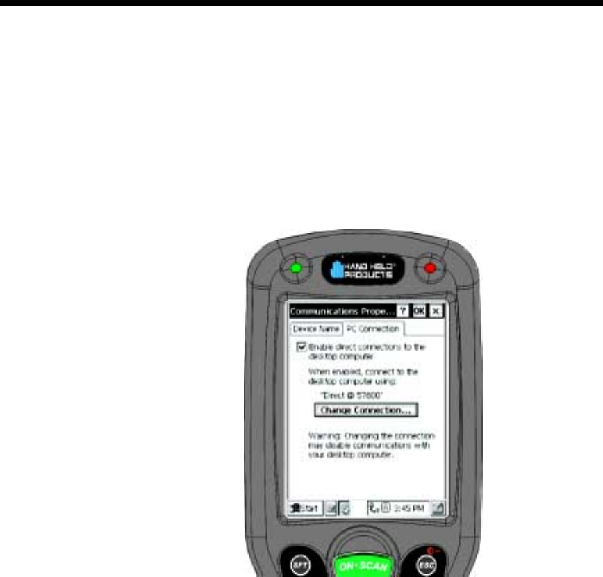
59
•
•
•
•
•
•
$))
The Communication Properties must be configured on Dolphin 7400 terminal in
order for it to communicate with the HomeBase/IntelliBase/USB HomeBase.
To set Communication Properties:
1. Select Start>Settings>Control Panel>Communication Settings.
2. Select the PC Connection tab.
Communication Properties
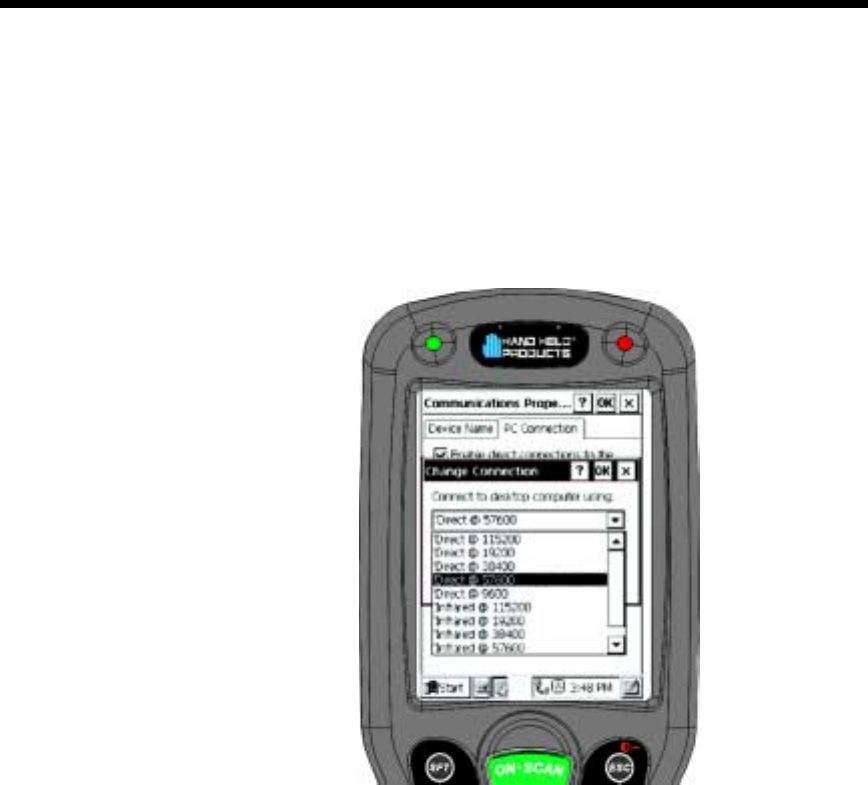
60
•
•
•
•
•
•
3. Select Change Connection and choose the desired option for connecting to the desktop
computer. Choose Direct if you are using a serial connection; choose Infrared for a
HomeBase connection; and IrDA for HomeBase/IntelliBase IrDA connection or USB
IrDA connection. and click OK.
4. Place the Dolphin 7400 in the HomeBase/IntelliBase/USB HomeBase.
5. On the Dolphin 7400 desktop, double-tap on ActiveSync.
)3#$53/
To use the USB HomeBase, you need the following equipment:
•
USB HomeBase
•
USB Cable
•
Power Supply
•
CD with USB-IrDA drivers
•
Windows® 98, Windows® Me or Windows® 2000 computer.
Note: The USB HomeBase does not support Windows
NT®
To install the USB HomeBase, follow these steps:
1. Plug in the power supply and connect it to the back of the USB HomeBase.
2. Plug the USB cable into the back of the USB home base.
3. Plug the other end of the USB cable into your PC.
Change Connection Screen
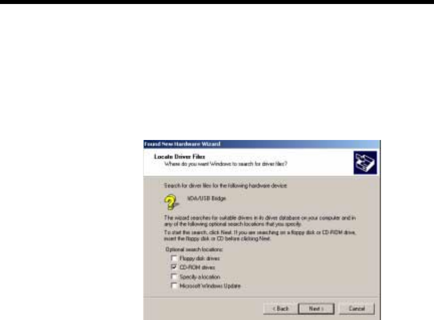
61
•
•
•
•
•
•
At this point, a dialog box appears on your PC instructing you that the system has
detected new hardware and it is searching for the Hand Held Products USB-IrDA
driver. Unless you have previously installed the USB HomeBase, the OS will be
unable to find one and the Found New Hardware Wizard screen shown below will
display on your PC’s screen.
In the "Locate Drive Files" dialog, check the CD-ROM drives checkbox and insert
the driver CD provided into the CD tray on your PC. There are sub-directories in
this directory for each type of Windows OS supported. Select stirusb.sys file in
the correct sub-directory for your PC:
•
w2k - Windows® 2000
•
win98 - Windows® 98
•
winme - Windows® Me
At this point, the hardware is installed and operating. You may need to reset your
PC to complete the installation process. You can verify that the USB driver is
functioning by watching the COMM LED on the USB home base. It should be
flashing red approximately every three seconds.
Once the USB home base is installed, you can use ActiveSync to connect to a
Dolphin 7400. These instructions assume that ActiveSync v3.1 is installed on your
PC.
In the ActiveSync connection settings, add checkmark to "Allow serial cable or
infrared connection to this COM port" and select "Infrared Port (IR)" for the COM
port as shown below. Do not check "Allow USB connection with this desktop
computer". It has no effect for the USB HomeBase.
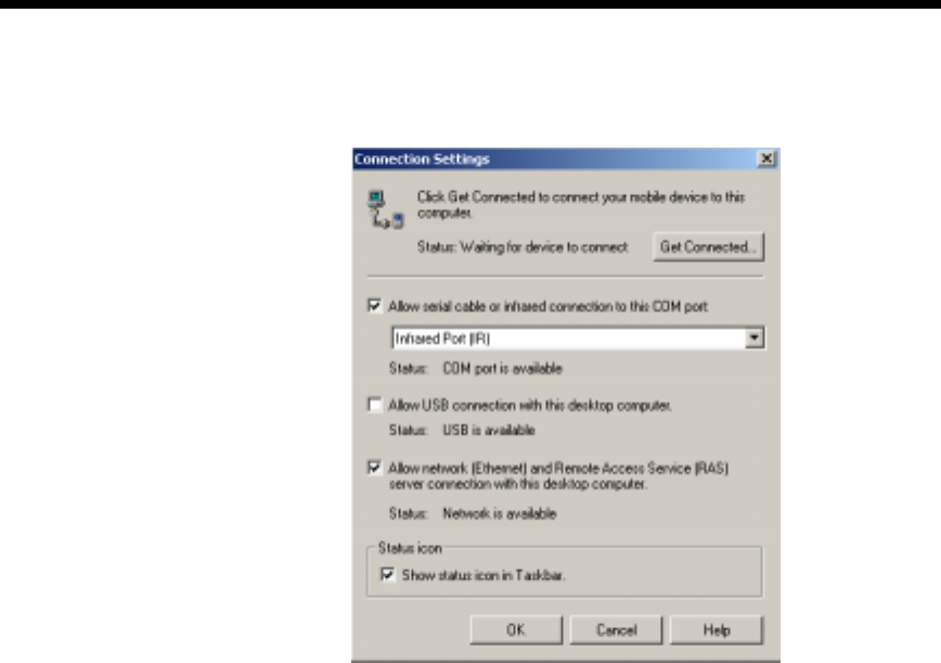
62
•
•
•
•
•
•
To configure the Dolphin 7400 terminal for communications, see the previous
section on Configuring the Dolphin Terminal.
$)%
To communicate with the Dolphin and any other devices connected to the
HomeBase/IntelliBase/USB HomeBase:
1. Insert the Dolphin into the terminal well of the HomeBase/IntelliBase/USB HomeBase.
If the Dolphin is in sleep mode, it will awaken into active state.
2. The DOCK LED on the HomeBase/IntelliBase/USB HomeBase will turn on. If the Dol-
phin does not turn on, or the LED does not light up, make sure that it is properly seated
in the terminal well and that the power supply is properly connected to the HomeBase/
IntelliBase/USB HomeBase and plugged into a functioning AC outlet.
3. Start your application on the Dolphin terminal or the host computer. Data can then
begin transmitting between the terminal and the devices connected to the Dolphin
HomeBase/IntelliBase/USB HomeBase.
When data transfer begins, the COMM LED on the Dolphin HomeBase/
IntelliBase/USB HomeBase will blink red and green. If the HomeBase/IntelliBase/
HomeBase will not communicate with the Dolphin, check the port connections to
ensure that the HomeBase/IntelliBase/USB HomeBase is correctly configured.
2)/663/
The HomeBase/IntelliBase/USB HomeBase may be desk or wall-mounted for
convenience and storage.
ActiveSync Connection Settings
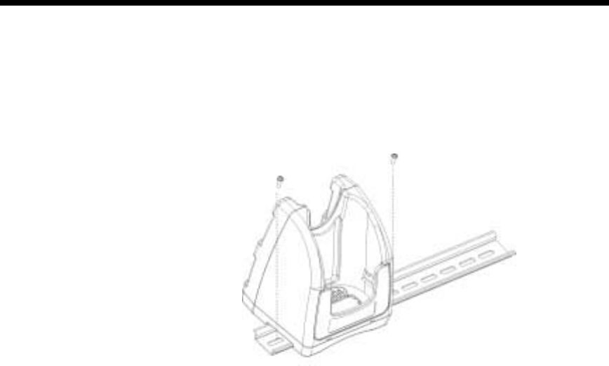
63
•
•
•
•
•
•
-2)B
The HomeBase/IntelliBase/USB HomeBase has a DIN rail (7.5 X 35 mm) slot on
the bottom to allow for secure desk attachment of the unit if desired.
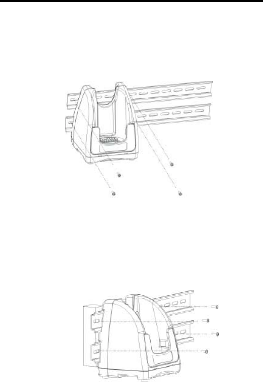
64
•
•
•
•
•
•
52)B
The HomeBase/IntelliBase/USB HomeBase also has two DIN rail (7.5 X 35mm)
slots on the back to allow for secure wall mounting of the unit if desired.
When using right-angle style RS-232 connector cable, the DIN rails may be
mounted directly to the wall. When using standard RS-232 connector cables, it is
recommended that the rails be mounted to the wall using a 25mm (1 in.) spacer to
allow for appropriate strain relief of the cables.
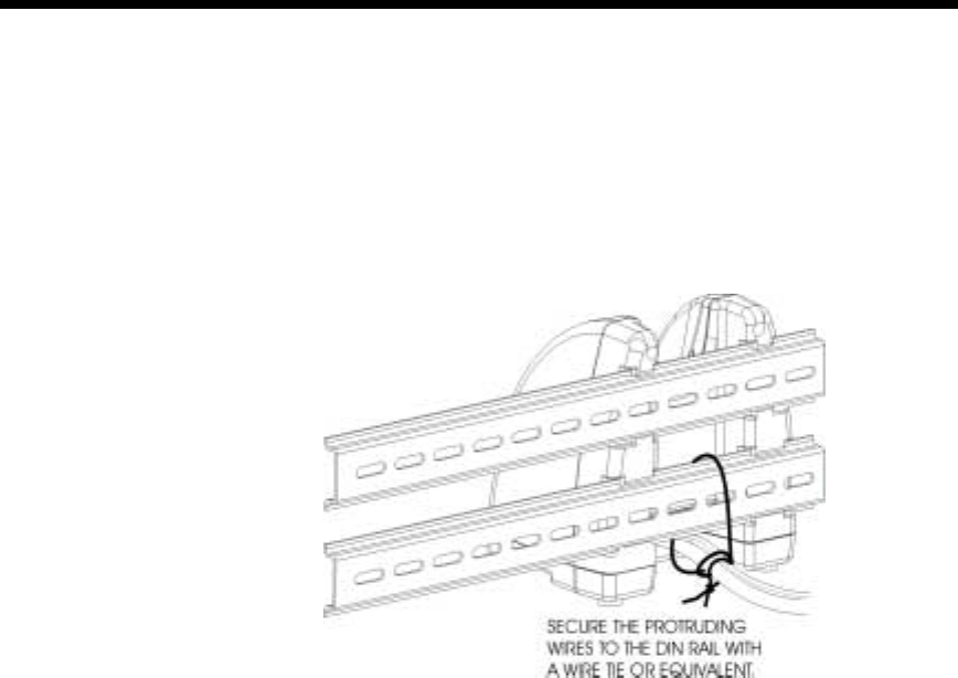
65
•
•
•
•
•
•
In either case, after wall mounting, it is recommended that the cables be secured to
the DIN rail through use of a wire tie to prevent damage to the HomeBase/
IntelliBase/USB HomeBase unit in case accidental or excessive force is applied to
the cables.

66
•
•
•
•
•
•
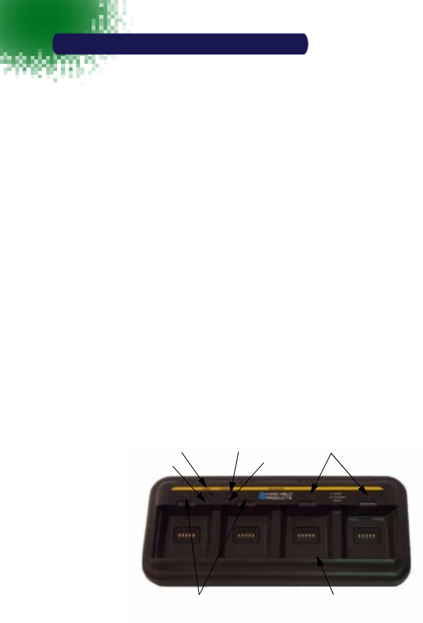
67
•
•
•
•
•
•
4XDG&KDUJHU
The Dolphin® 7400 QuadCharger provides intelligent battery
management for NiMH (Nickel Metal Hydride) Dolphin 7400 battery
packs.
The charger fully charges as many as four NiMH batteries in 2.5
hours. Charging slots work independently to control charging and
discharging of individual battery packs. The QuadCharger is
compatible with all models in the Dolphin® 7400 family of handheld
computers.
As battery packs charge, the charging circuitry uses a three-step
process that senses changes in temperature and voltage and drops
to a trickle charge when the packs are fully charged. This feature
allows the user to leave batteries in the charger indefinitely, which
maintains the batteries at peak capacity without damage. The
charger also resets and calibrates battery pack data to accurately
show battery status on the Dolphin display.
The QuadCharger also conditions and calibrates batteries for longer,
more consistent performance.
!""C$),#
,
Charging Pocket
Status LEDs
Status LEDs
Condition Switch
& Condition LED
Power Switch
& Power LED
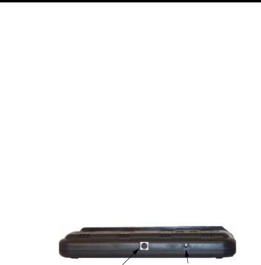
68
•
•
•
•
•
•
Charging Pocket
The QuadCharger has four charging pockets for charging and/or conditioning
batteries for your Dolphin 7400 terminal.
Power Switch
Press and hold the Power Switch for approximately one second, then release, to
turn on the Dolphin 7400 QuadCharger. The Power Switch LED is green when the
unit is on. To turn the charger off, press and hold the Power Switch for about two
seconds and then release. This feature prevents the unit from being accidently
turned off during use or on when not in use.
Condition Switch
Press the Condition Switch to start a battery conditioning cycle. The orange
Conditon Switch LED flashes during the conditioning cycle.
Status LEDs
A Status LED is located above each of the four battery pockets.
,
Power Supply Connector
Use this connector to attach a power supply to the Quad Charger. The universal
power supply accepts input voltages between 90-265 volts.
Communications Port
The communications port is for factory use only in programming the Quad
Charger.
Rear Panel of Dolphin 7400 Quad Charger
Power Supply ConnectorCommunications Port

69
•
•
•
•
•
•
$))C$)
Follow these steps to charge batteries in the QuadCharger:
1. Set up the charger for use
2. Supply power
3. Insert batteries
CAUTION: Do not attempt to recharge any battery pack in the Dolphin 7400
QuadCharger that is not manufactured by HHP especially for this device. To do so
will void your warranty and could damage the Dolphin 7400 QuadCharger.
)3C$)
The Dolphin 7400 QuadCharger should be setup on any dry, stable surface. DIN
rail slots on the bottom panel allow the charger to be wall or desktop-mounted for
easily adapting the unit to your environment.
The charger must be connected to a power source for any type of operation.
),%C$)
CAUTION: Using a non-HHP power cord voids your warranty and could result in
serious damage to the Dolphin 7400 QuadCharger’s circuitry.
Locate the AC power cord that came with the Dolphin 7400 QuadCharger. Plug
the cord into the power supply connector on the back of the unit and, then plug the
power cord into a wall socket.
Press and hold the Power Switch for approximately one second, then release, to
turn on the Dolphin 7400 QuadCharger. The GREEN power LED will illuminate
and the charger will undergo a self-diagnostic test.
)+),-
To insert a battery pack, place the end of the battery without the locking tab into
the bottom of the charging pocket and snap the battery into place with a hinging
motion. Once the battery is properly seated, the orange status LED for that
particular pocket will illuminate.
For best results, battery packs should be at room temperature before recharging
them; temperature has a marked effect on charging. The recommended
temperature range is 50° to 95° F (10° to 35° C).
The LEDs indicate the charging status of batteries as described in the chart
shown on the next page:
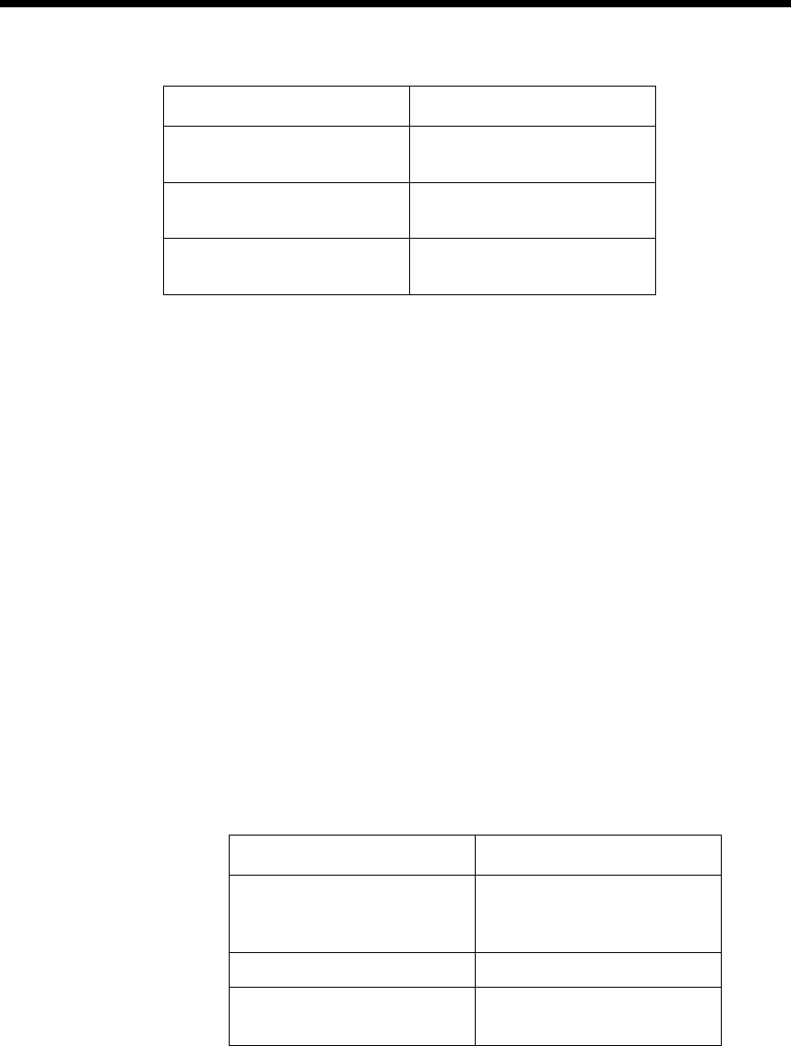
70
•
•
•
•
•
•
To remove a battery pack, push the locking tab down and pull the battery out from
the charging pocket with a hinging motion.
+),-
To service battery packs, insert batteries into the charging pockets and press the
Condition button. The Condition LED will flash during the conditioning cycle. This
starts an automatic process where batteries are completely discharged and then
recharged to full capacity in eight hours. The Condition and Calibrate cycle resets
and calibrates battery data so that the user gets longer, more consistent
performance from the batteries. HHP recommends that battery packs should be
serviced, or calibrated once a month.
Because the Dolphin 7400 QuadCharger is accumulating battery pack information
during the entire Condition and Calibrate cycle, it is important not to remove the
battery until the cycle has been completed and the Condition LED is no longer
flashing. Batteries inserted after the “Condition and Calibrate” switch has been
depressed will receive a standard charge. The chart below describes the Status
LEDs during the Condition and Calibrate cycle:
Status LED Description
Green Charging is complete and
battery is ready for service.
Orange Battery is being charged at a
maximum charge rate
Red Error was encountered during
charge cycle
Status of LEDs during Charging Cycle
Status LED Description
Solid Green
Cycle is complete. Battery
remains in trickle charge until
removed from the charger.
Flashing Orange Battery is being conditioned
Solid Red Error was encountered during
charge cycle
Status of LEDs during Condition and Calibrate Cycle

71
•
•
•
•
•
•
)
To maintain top performance from batteries, follow the guidelines below when
storing them:
Avoid storing batteries outside of the specified range of -4 to 104° F ( -20 to 40°C)
or in extremely high humidity.
For prolonged storage, do not keep batteries stored in a charger that is connected
to a power source.
During long-term storage, battery deactivation may tend to occur which may
cause charging to stop early during recharging after storage. This issue can be
handled by charging and discharging the battery several times. Also, the first
charging after prolonged storage may yield a lower than normal capacity. While
this will vary depending on the storage conditions, charging and discharging the
battery several times will almost completely restore capacity.
)
If you encounter problems with the Dolphin 7400 QuadCharger, refer to chart
below for possible solutions. If problems persist, please contact Hand Held
Products Technical Support.
Problem Issue
The ‘CHARGING” LED does not
come on when I insert a battery pack
into the Dolphin 7400 QuadCharger
Check the power connections on the
Dolphin 7400 QuadCharger. Also
check to ensure the POWER switch
is ON and the battery pack is
properly seated.
The red status LED comes on during
charging. Try to charge the battery in one of the
other charging pockets. If the red
Status LED comes on again, then the
problem is associated with the
battery pack. If the red status stays
with the charging pocket, the problem
is associated with the charging
circuity.
The red status LED remains on
without a battery in the charging
pocket.
An error occurred during the self-
diagnostic test for that particular
charging pocket. Call Hand Held
Products Technical Support.

72
•
•
•
•
•
•

73
•
•
•
•
•
•
'ROSKLQ0RELOH,QWHOOL%DVH|
,%$)
The Mobile IntelliBase provides power to the Dolphin terminal to
enable the terminal to charge its battery.
6*0$
The infrared, or Ir communications port, on the Mobile IntelliBase
connects with the IrDA port on the Dolphin terminal. With no pins or
contacts to break, Ir will work reliably for years. Reliable data
communications at speeds of up to 115k baud can be transmitted by
the Mobile IntelliBase.
The Mobile IntelliBase infrared connection to the terminal uses IrDA-
compliant hardware and software for a standard reliable connection.
$+)
The Mobile IntelliBase is a safe and convenient storage receptacle for
the Dolphin terminal.
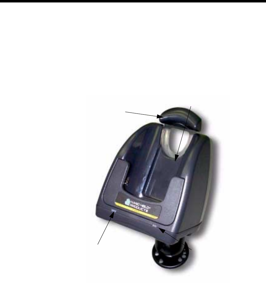
74
•
•
•
•
•
•
2,#
#,
The front panel of the Mobile IntelliBase has one slot:
Dolphin Terminal Well Place the Dolphin in this well to communicate with a host
device and to charge the Dolphin’s battery.
LEDs There are two LEDs on the front panel of the Mobile IntelliBase.
1. Dock LED Turns solid green when the Dolphin Terminal is properly seated into the
Dolphin Mobile IntelliBase.
Front Panel of Dolphin Mobile IntelliBase
Terminal
Well
DOCK LED COMM
LED
Spring-Arm
Assembly
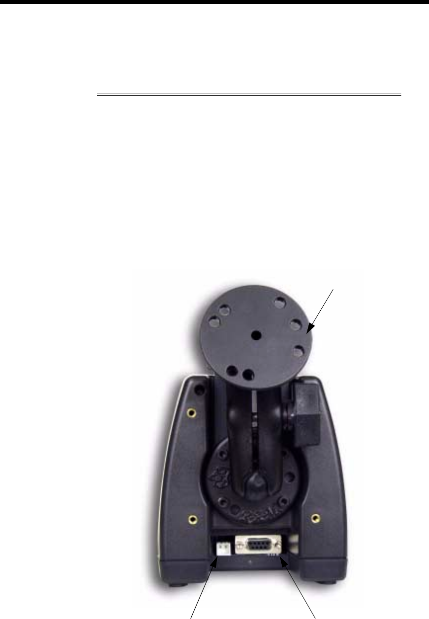
75
•
•
•
•
•
•
2. COMM LED Indicates the status of data transfer between the Host Device and the
Dolphin Terminal as described below:
,
Comm LED Description
Red LED
Data is being sent from the Host Device to the
Dolphin
Mobile IntelliBase.
Green LED
Data is being sent from the Dolphin Mobile
IntelliBase to the Host Device.
Orange LED
Data is being sent at high data rates.
Rear Panel of Dolphin Mobile IntelliBase
RS-232
Communications
Port
Power Supply
Connector
Mounting Bracket

76
•
•
•
•
•
•
There is a power supply connector and an RS-232 connector:
Power supply connector Use this connector to attach a power supply to the Mobile
IntelliBase. The power supply provides power for communications and battery
charging.
RS-232 Communications Port Use a standard serial cable to connect this port to a
host RS-232 device.
,2
A four-position Baud Rate switch, located on the bottom of the Mobile IntelliBase,
is used to select the communication baud rate. Switch position and the
corresponding baud rates are shown in the chart below.
!"#$#
Baud Rate Switch 1 Switch 2 Switch 3 Switch 4
OFFONONON
ON OFF OFF ON
ON OFF ON ON
ON ON OFF ON
ON ON ON ON
% !"#&
Baud Rate Switch 1 Switch 2 Switch 3 Switch 4
OFFONONOFF
ON OFF OFF OFF
ON OFF ON OFF
ON ON OFF OFF
ON ON ON OFF

77
•
•
•
•
•
•
,%)
When seated in the Mobile IntelliBase, the Dolphin terminal receives the power it
needs to charge the battery and to run its internal circuitry.
The Dolphin terminal can be stored indefinitely in the Mobile IntelliBase without
damage to the terminal or the Mobile IntelliBase. Keep the Mobile IntelliBase
plugged in so that the Dolphin terminal battery pack stays fully charged.
$))*
The Mobile IntelliBase supplies charging power to the Dolphin terminal so that the
terminal can monitor the charging of its battery pack. This charging method
protects the battery from being damaged by overcharging. Therefore, the Dolphin
terminal may be stored indefinitely in the Mobile IntelliBase without damage to the
terminal, the battery pack, or the Mobile IntelliBase.
To charge a Dolphin terminal, follow these steps:
1. Insert a battery pack into the Dolphin terminal.
2. Place the terminal, imager engine window up and the LCD visible, in the Terminal Well
of the Mobile IntelliBase.
3. Let it glide down into the well until it stops.
4. Once the Dolphin terminal is properly seated, the Dock LED on the
Mobile IntelliBase will be solid GREEN.
=$)
For maximum battery life, Hand Held Products recommends that you deep-cycle
(service) the battery twice before initial use and then, once a month thereafter.
Since the Dolphin 7400 Mobile Intellibase does not have deep-cycling capabilities,
it is recommended that you use the Battery Conditioning Utility software or
Dolphin Quad Battery Charger. See the Battery Management section in Chapter 3
for more information.
)3#$%2
The Mobile IntelliBase RS-232 interface allows the Dolphin terminal to
communicate to a personal computer, modem, or any standard RS-232 device
using a standard serial cable and communications software.
The IrDA 1.0 software stack is integrated into the Mobile IntelliBase to allow
communication between the cradle and devices such as modems or printers that
are not IrDA ready or do not communicate with a half duplex serial protocol. This
allows any full or half duplex RS-232 device to communicate through the
IntelliBase with no IrDA protocol software. See Tables 2 or 3 for the baud rate
switch settings.
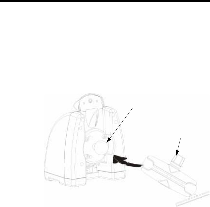
78
•
•
•
•
•
•
)2
Mounting the Mobile IntelliBase Spring Arm Assembly
The adjustable mounting bracket holds the terminal securely in place and gives
the user a variety of options for mounting the Mobile IntelliBase. See the
directions below for mounting the bracket.
To attach the bracket:
1. Loosen the turnscrew located on the side of the bracket.
2. Attach the bracket to the ball joint on the back of the Mobile IntelliBase and tighten the
turnscrew.
Ball joint
Turnscrew

79
•
•
•
•
•
•
Connecting the Cables
Connect the Mobile IntelliBase to the host computer or other device by plugging
an RS-232 serial cable into the RS-232 Communications Port on the rear of the
Mobile IntelliBase. Plug the other end of the RS-232 serial cable into the correct
port on the host RS-232 device.
The wiring of your cable depends on whether the other device is set up as a DCE
(Data Communications Equipment) or DTE (Data Terminal Equipment) device.
The Mobile IntelliBase Communication Port is configured as a DCE device. To
communicate with a DTE device such as a computer, use a standard (or straight-
through) RS-232 cable. To communicate with a DCE device, use either a null
modem adapter in line with a standard RS-232 cable, or a null-modem serial
cable.
You can make your own cables by following the pin configuration in the chart
below. To do so, you must determine if your host RS-232 device is 9-pin or 25-
pin, and whether it is configured as a DCE or DTE device.
),%2
The Mobile IntelliBase can be powered from either a 12 or 24 volt DC source.
Power is connected to the input power connector located on the rear of the Mobile
IntellieBase.
Hand Held Products recommends that you leave the Mobile IntelliBase connected
to its power source at all times, so that it is always ready to use.
Pin Configuration
HomeBase /Host
Port (DCE) IBM AT
DB9 (DTE) IBM XT
DB25
(DTE)
Modem
DB25 (DCE)
Pin / Input Signal
2 / (RD) 2 3 2
3 / (TD) 3 2 3
5 / (SG) 5 7 7
4 / (DTR) 4 20 6
6 / (DSR) 6 6 20
7 / (RTS) 7 4 5
8 / (CTS) 8 5 4
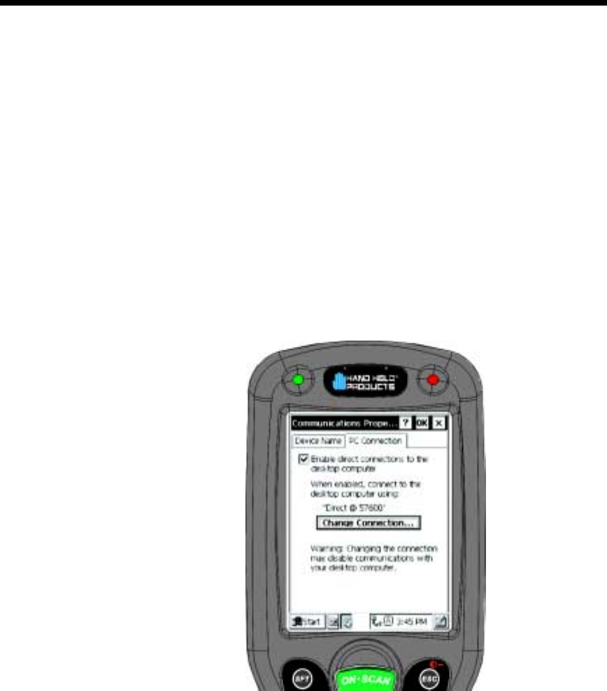
80
•
•
•
•
•
•
)
After connecting the cables and supplying power to the Mobile IntelliBase, set the
baud rate switch. Refer to the Baud Rate Tables earlier in this section for
guidance on setting the switch.
$))
The Communication Properties must be configured on Dolphin 7400 terminal in
order for it to communicate with the Mobile IntelliBase.
To set Communication Properties:
1. Select Start>Settings>Control Panel>Communication Settings.
2. Select the PC Connection tab.
Communication Properties
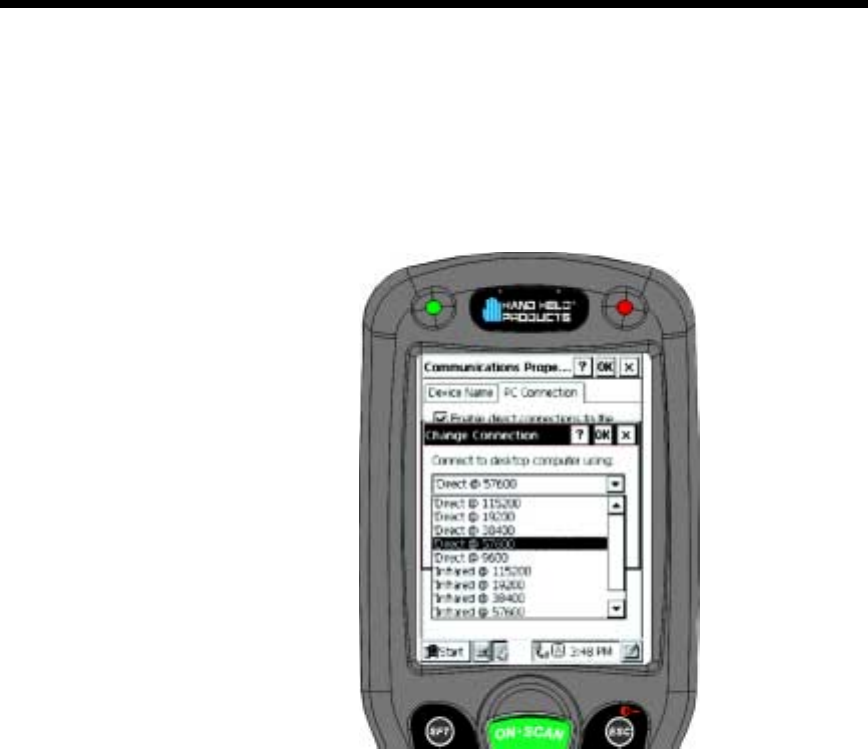
81
•
•
•
•
•
•
3. Select Change Connection and choose the desired option for connecting to the desktop
computer. Choose IrDA for Mobile IntelliBase IrDA connection and click OK.
4. Place the Dolphin 7400 in the Mobile IntelliBase.
5. On the Dolphin 7400 desktop, double-tap on ActiveSync.
Change Connection Screen

82
•
•
•
•
•
•

83
•
•
•
•
•
•
'HYHORSLQJ$SSOLFDWLRQV
Applications for the Dolphin 7400 handheld computer are developed
in the Microsoft® Windows® CE environment.
Microsoft Windows CE is a compact, highly efficient, scalable
operating system designed for embedded systems and products. Its
modular platform allows developers flexibility to customize it for a
variety of small footprint and mobile 32-bit devices. Windows CE
supports various hardware peripherals, devices and networking
systems. These include keyboards, touchscreens, serial ports,
Ethernet connections, and storage devices, such as PC cards.
The Dolphin 7400 platform contains most components of the basic
Windows® CE kernel except for Pocket Word, Pocket Excel and
Pocket Outlook. The kernel is the central module of the operating
system. It is the part of the operating system that loads first, and it
remains in main memory. Because it stays in memory, it is important
for the kernel to be as small as possible while still providing all the
essential services required by other parts of the operating system and
applications. Data synchronization also is not supported as the
Dolphin 7400 terminal is not designed for use as a single target.
To get started with developing applications for your Dolphin 7400
terminal, see the Dolphin 7400 Developer’s Getting Started Guide.
For more information, about Windows CE, check out these websites:
Microsoft Pocket PC (www.pocketpc.com) - General information
Chris De Herrera’s Windows CE website (www.cewindows.net) -
General information and FAQs
MSDN (msdn.microsoft.com/embedded) - Technical articles,
developer documentation and downloads
VBCE.com (www.vbce.com) - eMbedded Visual Basic information
and FAQs
VCCE.com (www.vcce.com) - eMbedded Visual Basic information
and FAQs

84
•
•
•
•
•
•

85
•
•
•
•
•
•
:DUUDQW\6XSSRUWDQG6HUYLFH
5
Welch Allyn Data Collection, Inc., d/b/a Hand Held Products ("HHP")
warrants its products to be free from defects in materials and
workmanship and to conform to HHP’s published specifications
applicable to the products purchased at the time of shipment. This
warranty does not cover any HHP product which is (i) improperly
installed or used; (ii) damaged by accident or negligence, including
failure to follow the proper maintenance, service, and cleaning
schedule; or (iii) damaged as a result of (A) modification or alteration
by the purchaser or other party, (B) excessive voltage or current
supplied to or drawn from the interface connections, (C) static
electricity or electro-static discharge, (D) operation under conditions
beyond the specified operating parameters, or (E) repair or service of
the product by anyone other than HHP or its authorized
representatives.
This warranty shall extend from the time of shipment for the duration
published by HHP for the product at the time of purchase ("Warranty
Period"). Any defective product must be returned (at purchaser’s
expense) during the Warranty Period to HHP’s factory or authorized
service center for inspection. No product will be accepted by HHP
without a Return Materials Authorization, which may be obtained by
contacting HHP. In the event that the product is returned to HHP or
its authorized service center within the Warranty Period and HHP
determines to its satisfaction that the product is defective due to
defects in materials or workmanship, HHP, at its sole option, will
either repair or replace the product without charge, except for return
shipping to HHP.
EXCEPT AS MAY BE OTHERWISE PROVIDED BY APPLICABLE
LAW, THE FOREGOING WARRANTY IS IN LIEU OF ALL OTHER
COVENANTS OR WARRANTIES, EITHER EXPRESSED OR
IMPLIED, ORAL OR WRITTEN, INCLUDING, WITHOUT
LIMITATION, ANY IMPLIED WARRANTIES OF
MERCHANTABILITY OR FITNESS FOR A PARTICULAR
PURPOSE.
HHP’S RESPONSIBILITY AND PURCHASER’S EXCLUSIVE
REMEDY UNDER THIS WARRANTY IS LIMITED TO THE REPAIR
OR REPLACEMENT OF THE DEFECTIVE PRODUCT. IN NO
EVENT SHALL HHP BE LIABLE FOR INDIRECT, INCIDENTAL, OR
CONSEQUENTIAL DAMAGES, AND, IN NO EVENT, SHALL ANY
LIABILITY OF HHP ARISING IN CONNECTION WITH ANY
PRODUCT SOLD HEREUNDER (WHETHER SUCH LIABILITY
ARISES FROM A CLAIM BASED ON CONTRACT, WARRANTY,
TORT, OR OTHERWISE) EXCEED THE ACTUAL AMOUNT PAID
TO HHP FOR THE PRODUCT. THESE LIMITATIONS ON
LIABILITY SHALL REMAIN IN FULL FORCE AND EFFECT EVEN

86
•
•
•
•
•
•
WHEN HHP MAY HAVE BEEN ADVISED OF THE POSSIBILITY OF SUCH
INJURIES, LOSSES, OR DAMAGES. SOME STATES, PROVINCES, OR
COUNTRIES DO NOT ALLOW THE EXCLUSION OR LIMITATIONS OF
INCIDENTAL OR CONSEQUENTIAL DAMAGES, SO THE ABOVE LIMITATION
OR EXCLUSION MAY NOT APPLY TO YOU.
All provisions of this Limited Warranty are separate and severable, which means
that if any provision is held invalid and unenforceable, such determination shall
not affect the validity of enforceability of the other provisions hereof.
The limited duration of the warranty for the Dolphin 7400 terminal is as described
below:
•
Terminals with an integrated imager are covered by a two-year limited warranty.
If equipped with a touch screen display, the display is covered by a one-year
limited warranty. If equipped with a Type II PCMCIA integrated radio card, the
radio card is covered by a one-year limited warranty.
The limited duration of the warranty for the Dolphin HomeBase/IntelliBase, USB
HomeBase, Mobile IntelliBase and QuadCharger is for one year.
The limited duration of the warranty for batteries is one year. The battery life will
be greatly increased when following the specific battery instructions in the user
guide. Rechargeable batteries are highly susceptible to “battery memory” and if
instructions are not followed, the amount of hours of usage and the life of the
battery are greatly reduced.
Batteries returned to Hand Held Products in this reduced state may or may not be
replaced under this warranty.
Hand Held Products, Inc. extends these warranties only to the first end-users of
the products. These warranties are non-transferable.
/%,/
Should the Dolphin terminal or any of the peripherals prove to be defective within
the stated warranty period from the of date of purchase, return the product, as
described in the RMA procedures below, and we will, at our option, repair or
replace the product, to whatever extent HHP deems necessary to restore the
product to proper operating condition, without any charge to you.

87
•
•
•
•
•
•
If you purchased the product from an Authorized Hand Held Products Reseller,
contact the Reseller with the unit’s serial number. Your Reseller will contact Hand
Held, on your behalf, to arrange for the unit to be serviced.
If you purchased the product directly from Hand Held, or have been instructed by
your Reseller to contact Hand Held directly, call the Customer Services
Department in your area to request a Repair Maintenance Authorization (RMA)
number.
Note: An RMA number is not needed for service at the Europe, the Middle East, Africa
or United Kingdom repair facilities.
North America:
(TEL) 1-(800)-782-4263
(FAX)+1-(704)-566-9904
Latin America
(TEL)+1-(941)-263-7600
(FAX)+1-(941)-263-9689
Europe, Middle East and Africa:
(TEL)+31-40 24 24 486
(FAX)+31-40 24 25 672
The United Kingdom:
(TEL)+44 (0) 1925 240 055
(FAX)+44 (0) 1925 245 225
Asia Pacific
(TEL) +852 2511 3050
(FAX) +852 2511 3557
You must have an RMA number to receive service from the repair facility for North
and South America, Asia and the Pacific Rim. Failure to obtain an RMA number
before shipping your product to this repair facility can delay the processing of your
repair request.
When calling for service at any of our repair facilities, please be prepared to give
the following information:
· Product's type and serial number
· Brief description of problem
· Dated Proof-of-Purchase

88
•
•
•
•
•
•
Place the product in its original packaging with a copy of your original invoice and
ship the product prepaid to the appropriate address below:
North and South America, Asia, Pacific Rim:
Hand Held Products
Products Services Department
7510 East Independence Blvd., #100
Charlotte, NC 28227-9411
RMA Number:__________________________
Europe, Middle East and Africa :
Hondsruglaan 87D
5628 DB Eindhoven
The Netherlands
The United Kingdom :
Dallam Court
Dallam Lane Warrington
Cheshire WA2 7LT
United Kingdom
If your equipment is still covered under the initial end-user’s product warranty,
please notify the Product Services Representative when you call. Please include
a copy of the original invoice in the package to avoid possible service delays. For
your protection, we recommend you insure any equipment being sent to HHP.
After repair or replacement of the equipment, Hand Held Products will ship the
product, at our cost, to your location. Non-warranty repairs will be returned, at the
customer’s expense, unless otherwise requested. Units currently under a service
agreement will be shipped per the service agreement.
Please make note of the RMA number (if required) before shipping and the
product’s serial number for future reference.
/%1D5
Hand Held Products offers a variety of service plans on our hardware products.
These agreements offer continued coverage for your equipment after the initial
warranty expires. For more information, contact your Hand Held sales
representative, customer account representative or the Product Service Marketing
Manager or your Authorized Reseller.

89
•
•
•
•
•
•
*
If you have a question or problem with your Dolphin terminal or Dolphin
HomeBase, you can get technical assistance from Hand Held’s Application
Support department.
Application Support - North and South America, Asia and Pacific Rim:
(TEL) 1-(800) 782-4263
(FAX) 1-(704) 532-4191
8:30 a.m. and 5:30 p.m., Eastern Time, Monday through Friday
Application Support - Europe, Middle East and Africa:
(TEL)+31-40 24 24 486
(FAX)+31-40 24 25 672
9 a.m. - 5 p.m., Central European Time, Monday through Friday
Application Support - The United Kingdom:
(TEL)+44 1925 240 055
(FAX)+44 1925 631 280
9 a.m. - 5:30 p.m., UK Time, Monday through Friday

90
•
•
•
•
•
•

91
•
•
•
•
•
•
$SSHQGL[$
Use the keyboard shortcuts in the chart below to navigate the Dolphin
7400 terminal’s keyboard.
Windows Keyboard Shortcuts
Press To
CTRL + C Copy
CTRL + X Cut.
CTRL + V Paste.
CTRL + Z Undo.
DELETE Delete.
CTRL + RIGHT ARROW Move the insertion point to the beginning
of the next word.
CTRL + LEFT ARROW Move the insertion point to the beginning
of the previous word.
CTRL + DOWN ARROW Move the insertion point to the beginning
of the next paragraph.
CTRL + UP ARROW Move the insertion point to the beginning
of the previous paragraph.
SHIFT with any of the arrow keys Select more than one item in a window or
on the desktop, or select text within a
document.
CTRL+A Select all.
ALT+ENTER View properties for the selected item.
ALT+TAB Switch between open items.
ALT+ESC Cycle through items in the order they were
opened.
CTRL+ESC Display the
Start
menu.
ALT+Underlined letter in a menu name Display the corresponding menu.
Underlined letter in a command name on
an open menu Carry out the corresponding command.
BACKSPACE View the folder one level up in My
Computer or Windows Explorer.
ESC Cancel the current task.

92
•
•
•
•
•
•
3)2<
The Dolphin 7400 terminal keyboard features the standard Windows modifier
keys, Alt, Ctrl and Shift. The Shift key only modifies the next key pressed; it must
be pressed before each key you wish to make lower case. For single-handed
operation, the Shift key only modifies the next key pressed; it must be pressed
before each key you wish to make lower case. For multiple lower case characters,
hold the Shift key down with one hand while typing with the other. Functions of the
Alt and Ctrl keys are dependent on the software application in use.
There are two additional modifier keys located on the bottom row of the keyboard.
Use these keys in combination with other keys to type the corresponding color-
coded characters and functions. The Red and Blue keys only modify the next key
pressed; these keys must be pressed and released before each key you wish to
modify to the Blue or Red case. See the charts below for key combinations that
access the functions and special characters using these keys.
!&=<*6;<
Blue Key Functions & Characters For 43-Key Alpha/Numeric
Keyboard
Key Combination Function/Special Character
Double tap Blue key Activate/Deactivate Mouse Utility
Blue key + D - (minus)
Blue key + H _ (underscore)
Blue key + L =
Blue key + P +
Blue key + Q ;
Blue key + R :
Blue key + S *
Blue key + T /
Blue key + U @
Blue key + X \

93
•
•
•
•
•
•
* Exit the mouse utility prior to adjusting the contrast.
<$
Use the key combinations listed below to access certain keyboard functions or to
use special characters that are not defined on the 43-key version of the Dolphin
7400 keyboard.
Red Key Functions & Characters For 43-Key Alpha Shifted
Numeric Keyboard
Key Combination Function/Special Character
Red key + ESC Lightens Contrast*
Red key + TAB Darkens Contrast*
Red key + SFT Toggles on Caps Lock
Red key + Q F1
Red key + R F2
Red key + S F3
Red key + T F4
Red key + U F5
Red key + V F6
Red key + W F7
Red key + X F8
Red key + Y START
Red key + Z INS (insert)
Red key + SP BKSP (backspace)
Red key + BACKLIGHT KEY DEL (delete)
Key Combinations Using NUM & SFT Keys
Key/Key Combination Function/Special Character
NUM + SFT + A !
NUM + SFT + B @
NUM + SFT + C #
NUM + SFT + E $
NUM + SFT + F %
NUM + SFT + G ^
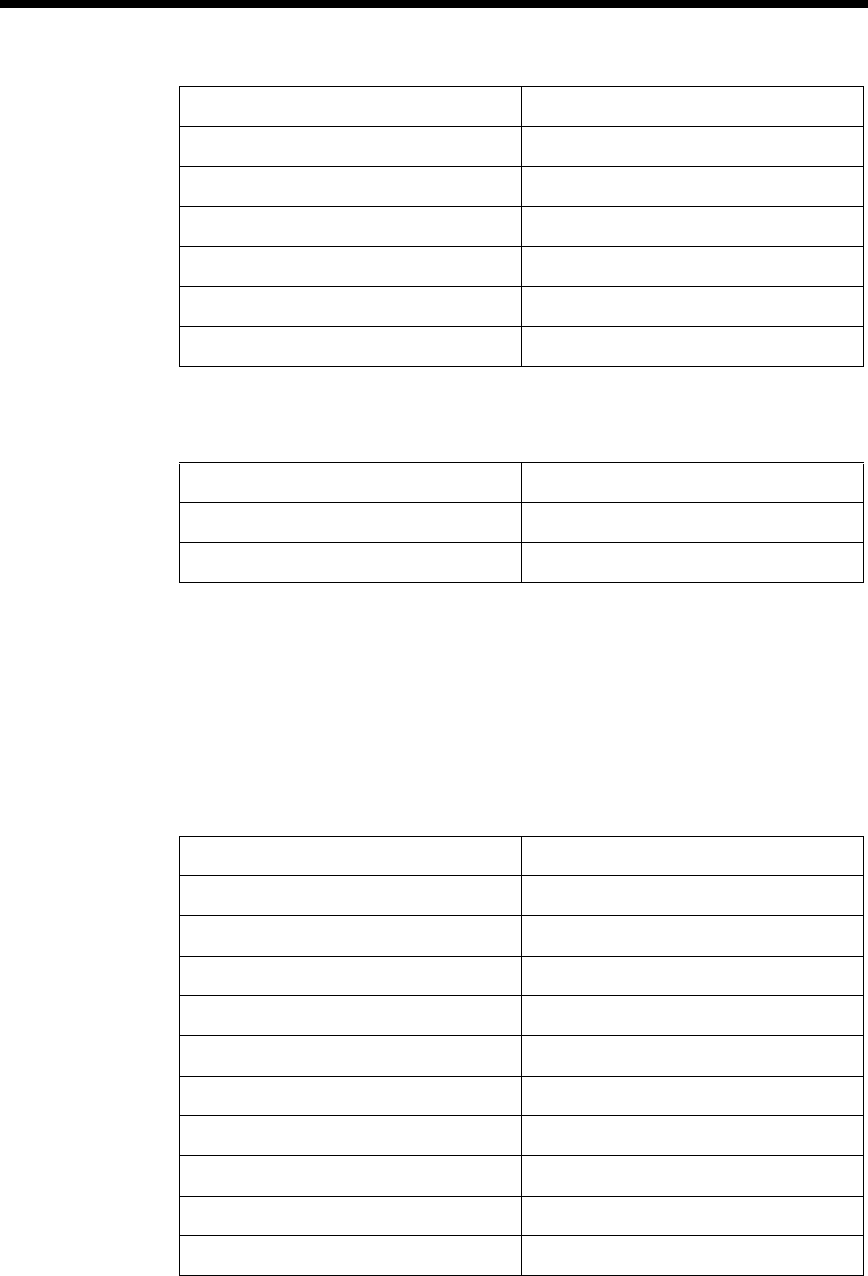
94
•
•
•
•
•
•
&'<;6*
NUM + SFT + I &
NUM + SFT + J *
NUM + SFT + K (
NUM + SFT + M >
NUM + SFT + N )
NUM + SFT + O <
Key Combinations Using Blue & SFT Keys
Key/Key Combinations Function/Special Characters
Blue + SFT + T ?
Blue + SFT + X |
Key Combinations Using NUM & SFT Keys
Key/Key Combination Function/Special Character
Blue Key Functions & Characters For 35-Key Numeric/Alpha
Keyboard
Key Combination Function/Special Character
Double tap Blue key Activate/Deactivate Mouse Utility
Blue key + . +
Blue key + , -
Blue key + F1 ;
Blue key + F2 :
Blue key + F3 /
Blue key + F4 \
Blue key + SP _
Blue key + DEL @
Blue key + 0 (zero) =

95
•
•
•
•
•
•
<$
Use the key combinations listed below to access certain keyboard functions or to
use special characters that are not defined on the 35-key version of the Dolphin
7400 keyboard.
Key Combinations Using ALPHA & SFT Keys
Key/Key Combination Function/Special Character
ALPHA + SFT + 1 !
ALPHA + SFT + 2 @
ALPHA + SFT + 3 #
ALPHA + SFT + 4 $
ALPHA + SFT + 5 %
ALPHA + SFT + 6 ^
ALPHA + SFT + 7 &
ALPHA + SFT + 8 *
ALPHA + SFT + 9 (
ALPHA + SFT + 0 )
ALPHA + SFT + . (period) >
ALPHA + SFT + , (comma) <
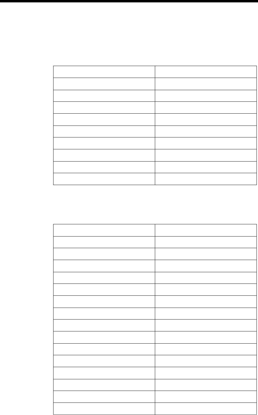
96
•
•
•
•
•
•
'E<#*;
Blue Key Functions & Characters For 56-Key
Full Alpha Numeric Keyboard
Key Combination Function/Special Character
Double tap Blue key Activate/Deactivate Mouse Utility
Blue key + . +
Blue key + , -
Blue key + A ;
Blue key + B :
Blue key + C /
Blue key + D \
Blue key + E _
Blue key + F @
Red Key Functions & Characters for 56-Key
Full Alpha Numeric Keyboard
Key Combination Function/Special Character
Red key + ESC Lightens Contrast*
Red key + TAB Darkens Contrast*
Red key + SFT Toggles on Caps Lock
Red key + A F1
Red key + B F2
Red key + C F3
Red key + D F4
Red key + E F5
Red key + F F6
Red key + G F7
Red key + H F8
Red key + I F9
Red key + J F10
Red key + K F11
Red key + L F12

97
•
•
•
•
•
•
* Exit the mouse utility prior to adjusting the contrast.
<$
Use the key combinations listed below to access certain keyboard functions or to
use special characters that are not defined on the 56-key version of the Dolphin
7400 keyboard.
Red key + M F13
Red key + N F14
Red key + O F15
Red key + P F16
Red key + Q F17
Red key + R F18
Red key + S F19
Red key + T F20
Red key + U F21
Red key + V F22
Red key + W F23
Red key + X F24
Red key + Y Z
Key Combinations Using SFT & Number Keys
Key/Key Combination Function/Special Character
SFT + 1 !
SFT + 2 @
SFT + 3 #
SFT + 4 $
SFT + 5 %
SFT + 6 ^
SFT + 7 &
SFT + 8 *
SFT + 9 (
Red Key Functions & Characters for 56-Key
Full Alpha Numeric Keyboard
Key Combination Function/Special Character

98
•
•
•
•
•
•
SFT + 0 )
SFT + . (period) >
SFT + , (comma) <
Key Combinations Using SFT & Number Keys
Key/Key Combination Function/Special Character
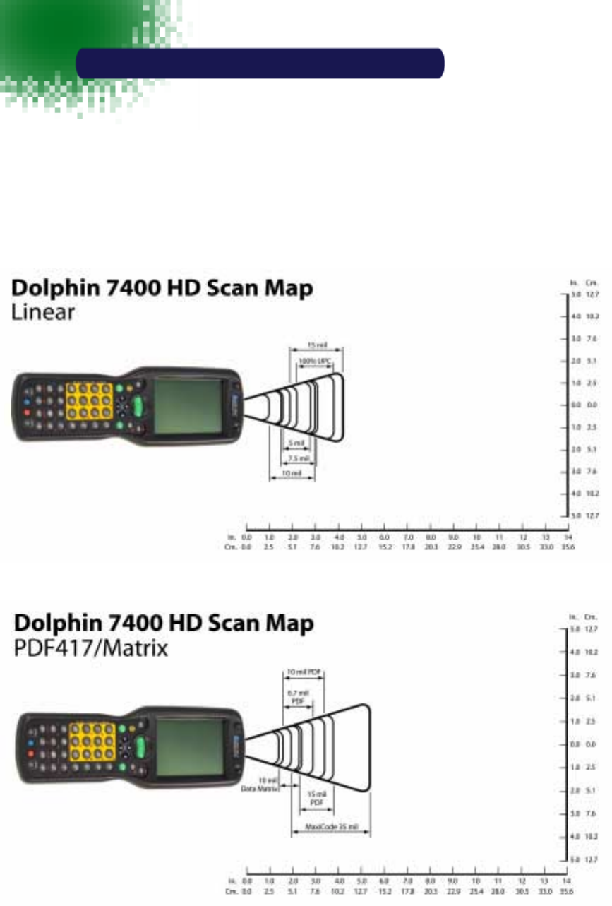
99
•
•
•
•
•
•
$SSHQGL[%
!""2
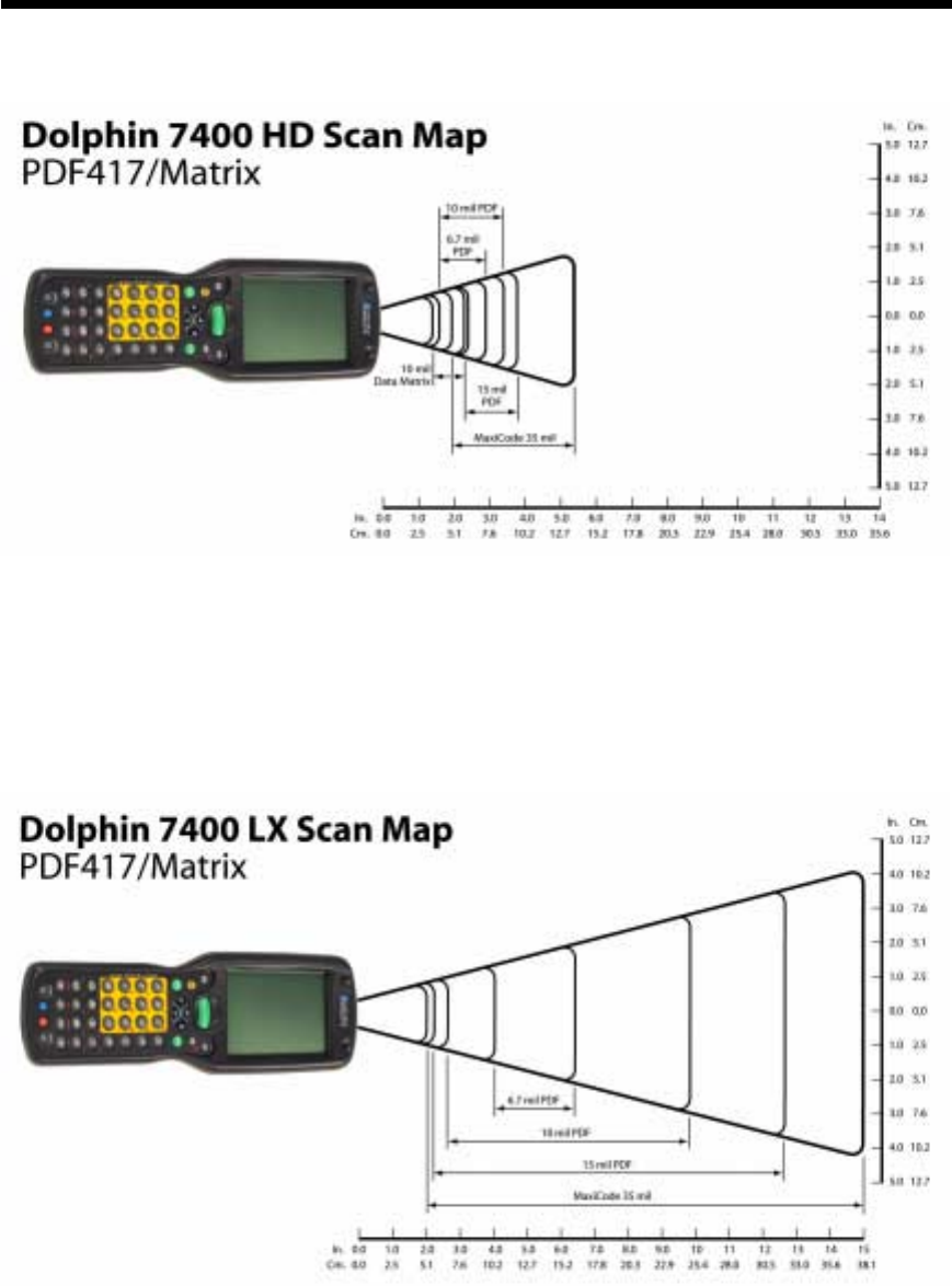
100
•
•
•
•
•
•

4619 Jordan Road
P.O. Box 188
Skaneateles Falls, NY 13153-0187
7400/UG Rev h