Honeywell 7800LG Dolphin® 7800 Mobile Computer User Manual 2 of 2
Honeywell International Inc Dolphin® 7800 Mobile Computer 2 of 2
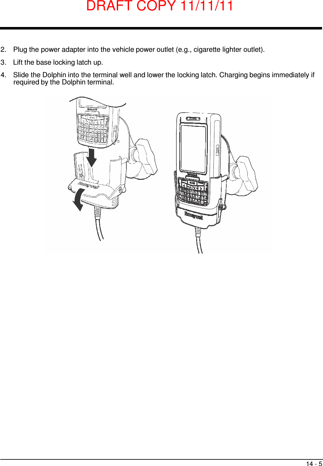
UserManual.wiki
>
Honeywell
>
7800LG User Manual
>
user manual 2 of 2
Contents
1.
user manual 1 of 2
2.
user manual 2 of 2
user manual 2 of 2
Navigation menu
Upload a User Manual
Namespaces
Wiki Guide
HTML
PDF
Info
Views
User Manual
Discussion / Help
Navigation


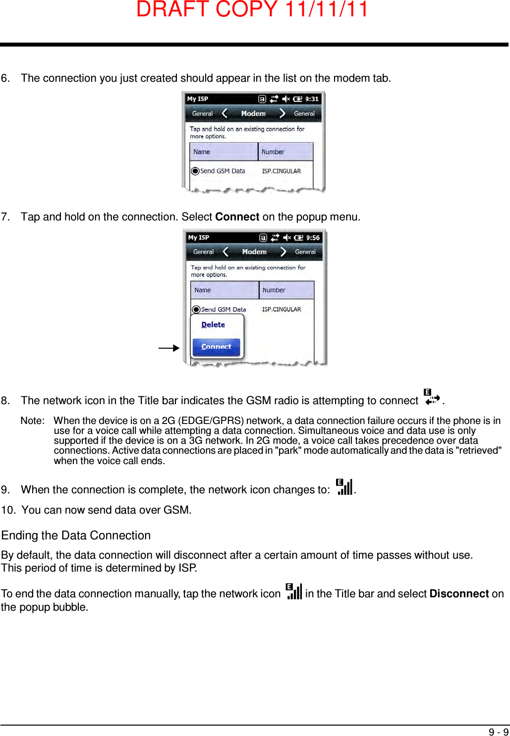


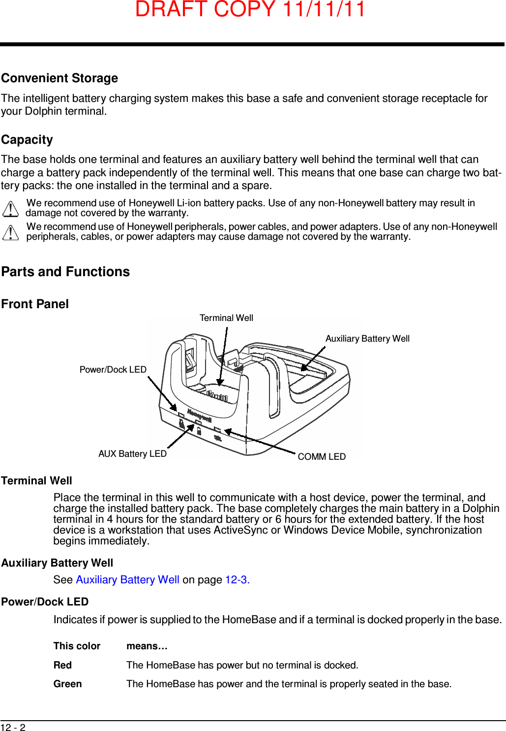
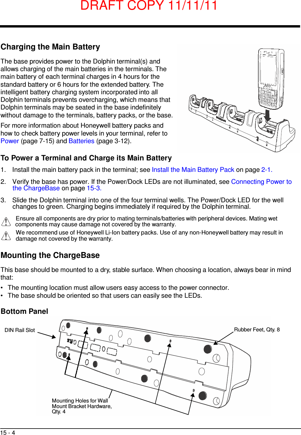
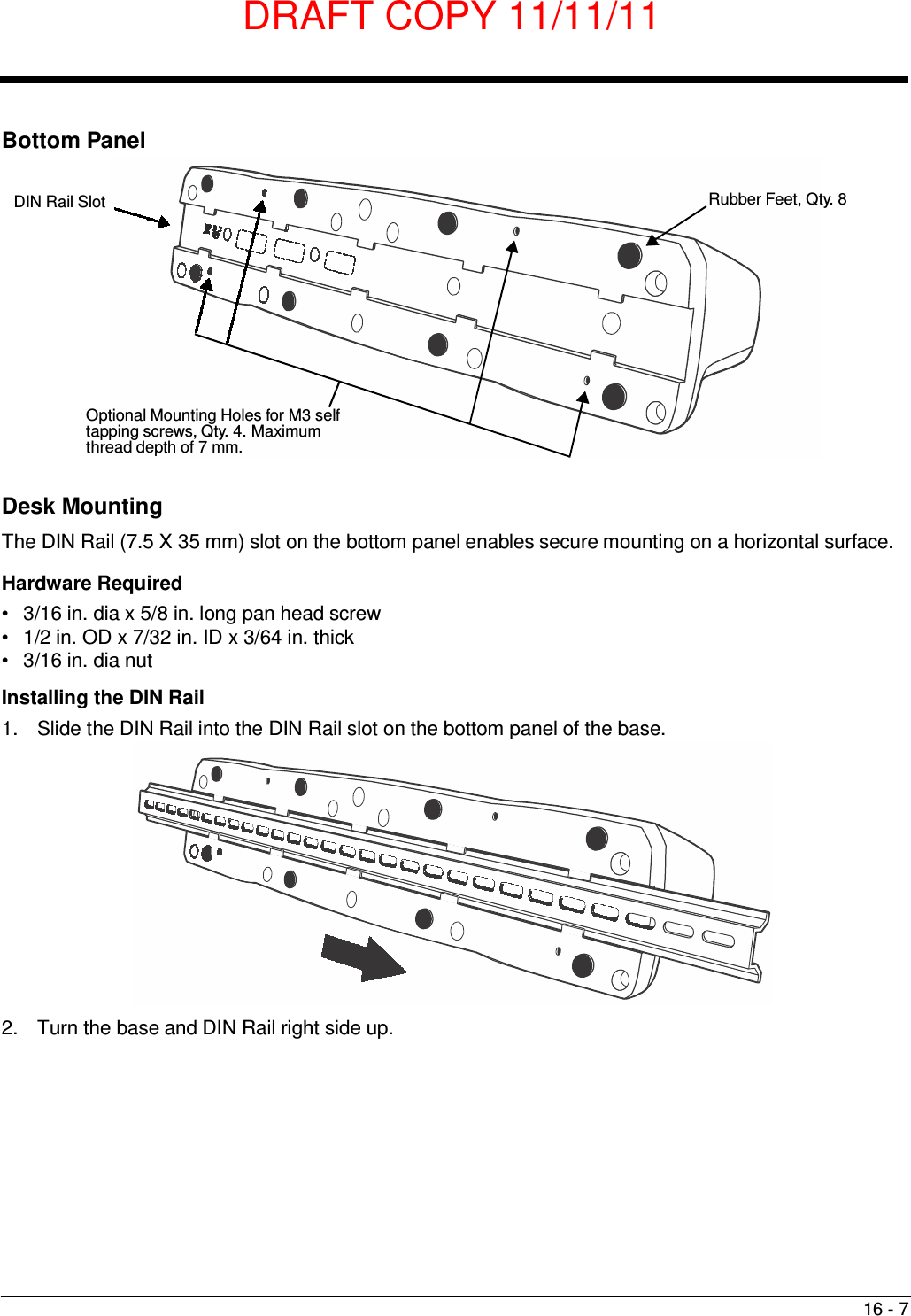
![DRAFT COPY 11/11/11 12 - 7 Mounting the HomeBase Set the base on a dry, stable surface, such as a desktop or workbench near an electrical outlet. Be sure to provide enough workspace with good lighting for the user to view and operate the Dolphin terminal while it is in the base. When choosing a mounting location, bear in mind that the location must allow users' easy access to the Auxiliary Battery Well and the back panel of the HomeBase where the USB port and the power jack are located. Optional Hardware Mount On the bottom of the HomeBase there are four mounting holes with a maximum depth of 7 mm that can be used to secure the base to a horizontal surface such as a desktop or workbench using M3 self tap- ping screws. Optional Mounting Holes for M3 self tapping screws, Qty. 4. Maximum thread depth of 7 mm. 101 mm [3.98 in.] 98 mm [3.86 in.] CL 90 mm [3.54 in.]](https://usermanual.wiki/Honeywell/7800LG.user-manual-2-of-2/User-Guide-1588433-Page-47.png)

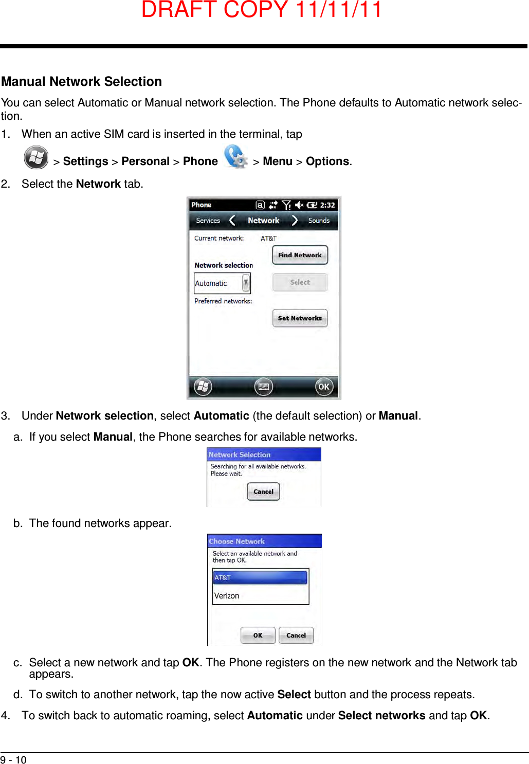
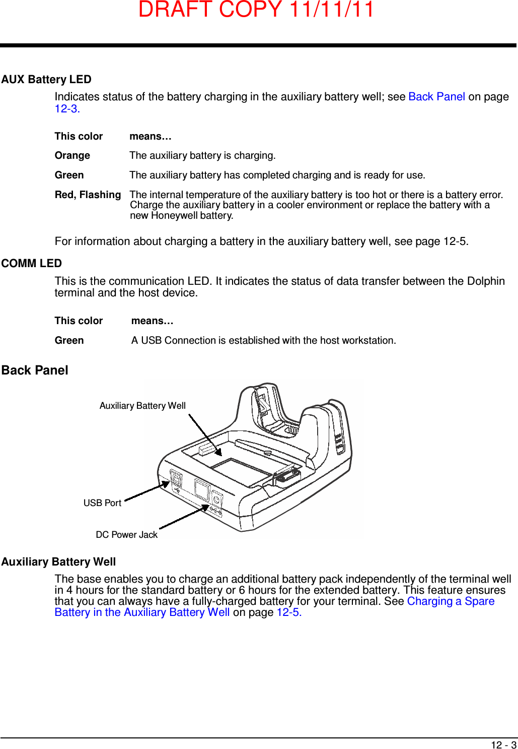
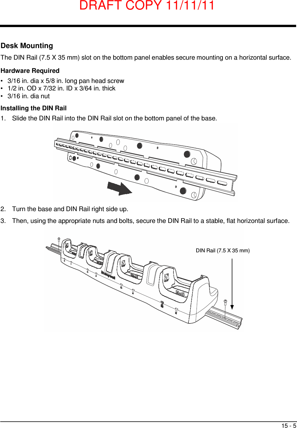
![DRAFT COPY 11/11/11 13 - 8 Optional Hardware Mount On the bottom of the HomeBase there are four mounting holes with a maximum depth of 7 mm that can be used to secure the base to a horizontal surface such as a desktop or workbench using M3 self tap- ping screws. Optional Mounting Holes for M3 self tapping screws, Qty. 4. Maximum thread depth of 7 mm. 101 mm [3.98 in.] 98 mm [3.86 in.] CL 90 mm [3.54 in.]](https://usermanual.wiki/Honeywell/7800LG.user-manual-2-of-2/User-Guide-1588433-Page-56.png)


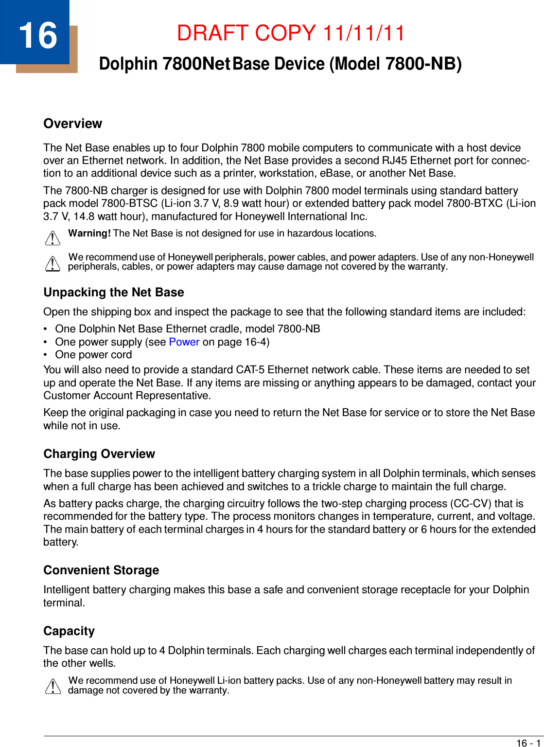

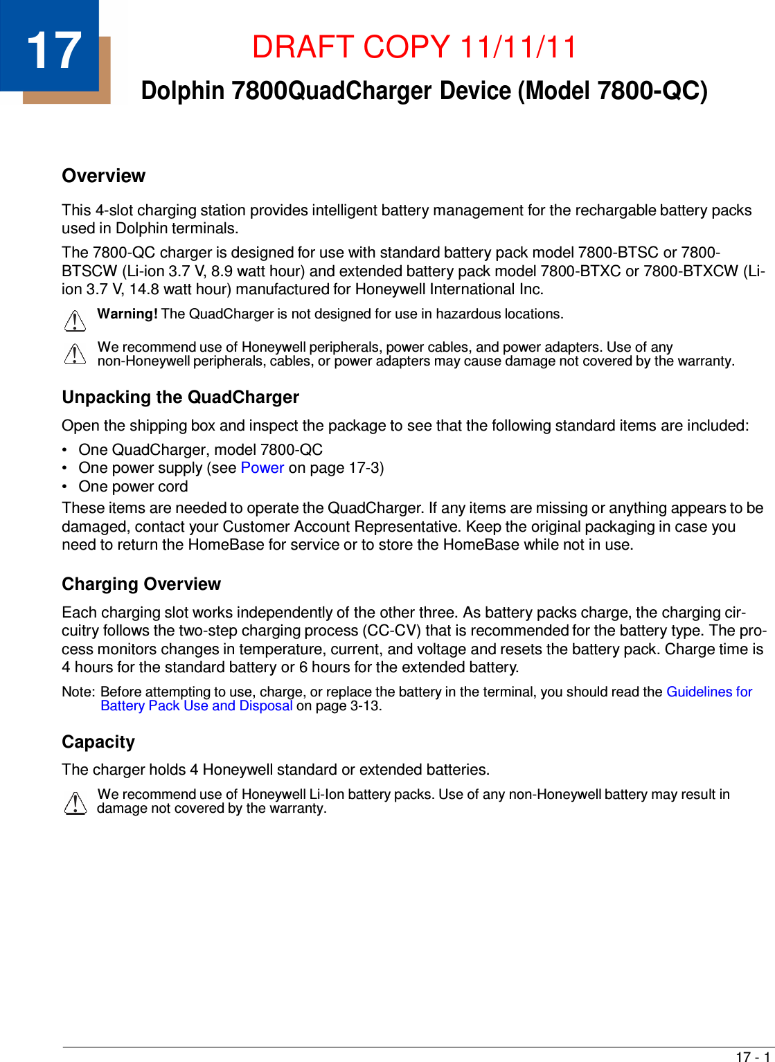
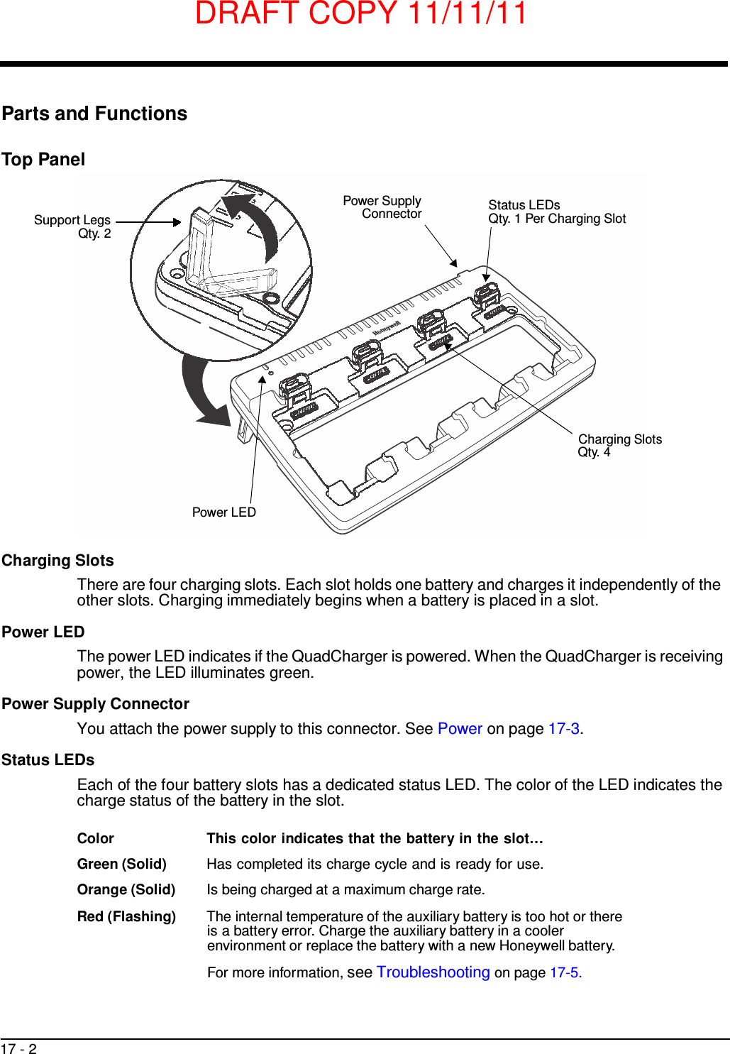
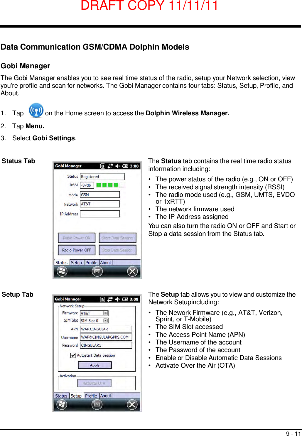
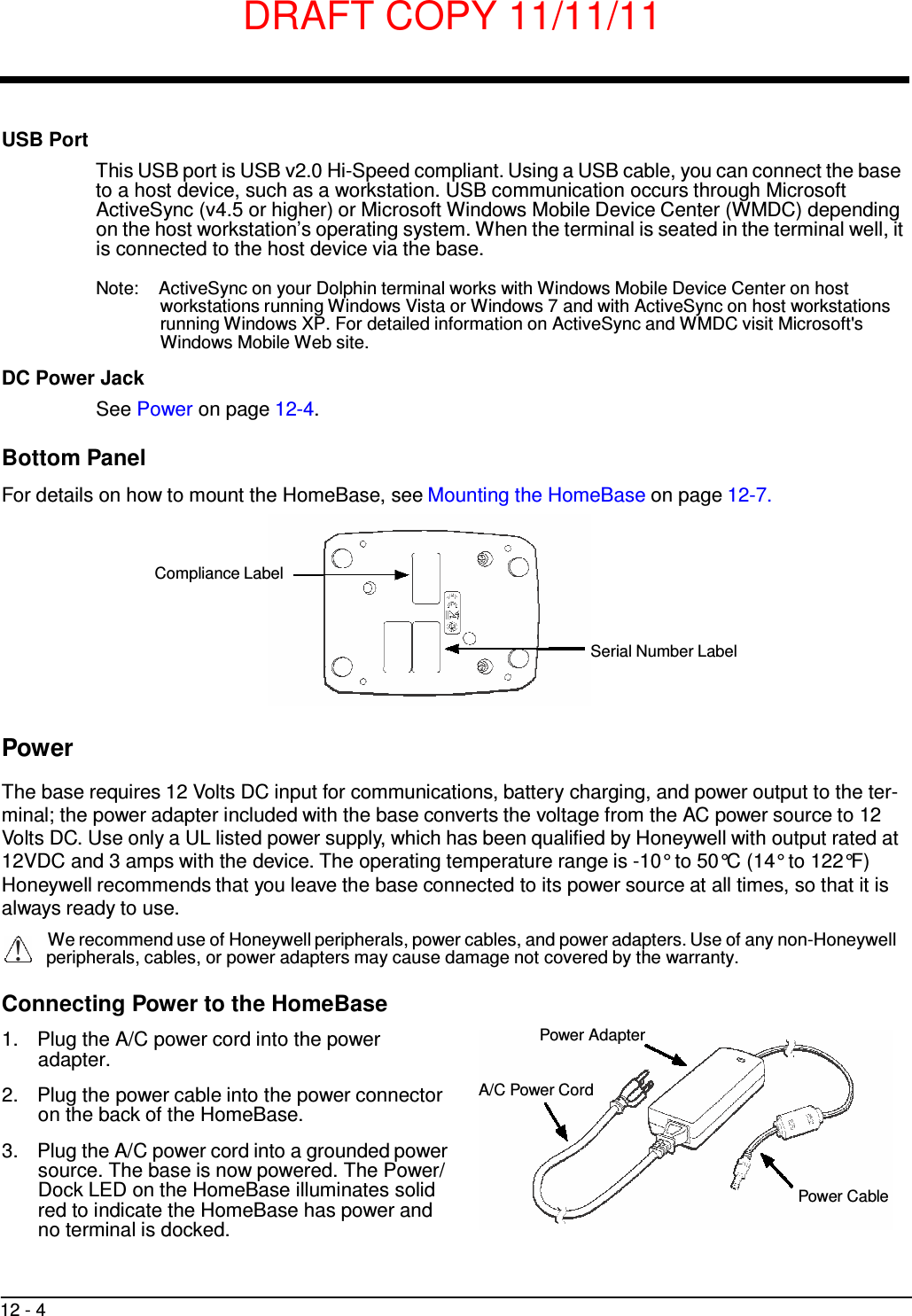
![DRAFT COPY 11/11/11 17 - 4 Mounting the QuadCharger The charger should be located on a dry, stable surface and can be mounted on a flat, horizontal surface such as a desktop or workbench. When choosing a location, always bear in mind that: • the mounting location must allow users easy access to the power connector. • the charger should be oriented so that users can easily insert and remove battery packs and see the status LEDs. Optional Hardware Mount Bottom Panel 268.6 mm [10.57 in.] 93 mm [3.66 in.] 45mm [1.77 in.] B B A A 60 mm [2.36 in.] 90 mm [3.54 in.] B B Optional Mounting Holes Option Size Qty. A 6 mm [0.24 in.] Dia. thru hole for #6 Flat Head Phillips Dry- wall-to-Wood Screws 2 B Mounting holes for M3 self tapping screws, maximum thread depth of 7 mm 4](https://usermanual.wiki/Honeywell/7800LG.user-manual-2-of-2/User-Guide-1588433-Page-80.png)