Honeywell 7800LW Dolphin® 7800 Mobile Computer User Manual
Honeywell International Inc Dolphin® 7800 Mobile Computer
UserManual.wiki
>
Honeywell
>
7800LW User Manual
>
user manual
Contents
1.
user manual
2.
User Manual
user manual
Navigation menu
Upload a User Manual
Namespaces
Wiki Guide
HTML
PDF
Info
Views
User Manual
Discussion / Help
Navigation


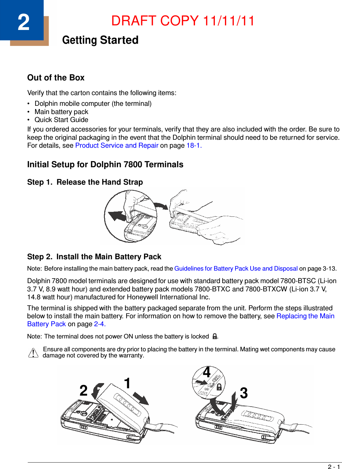
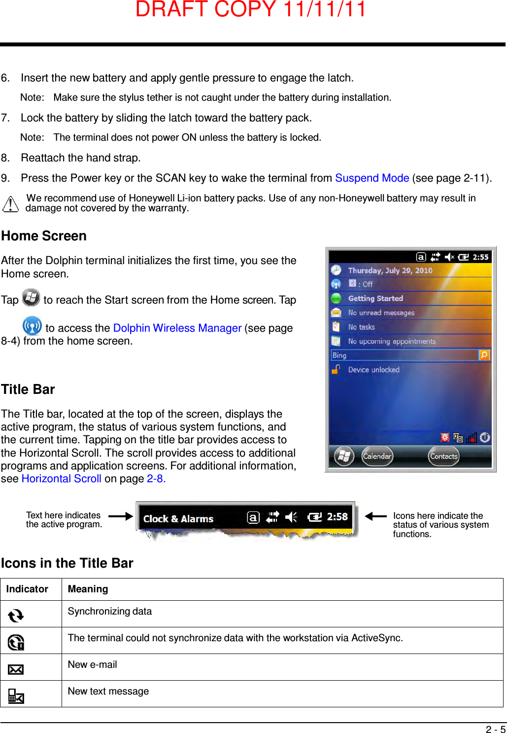
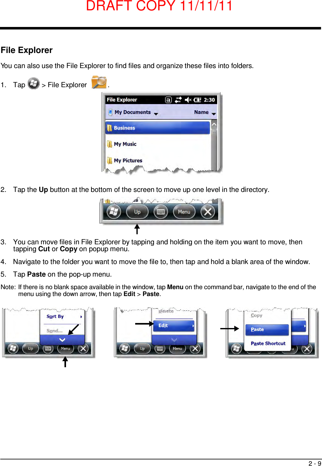


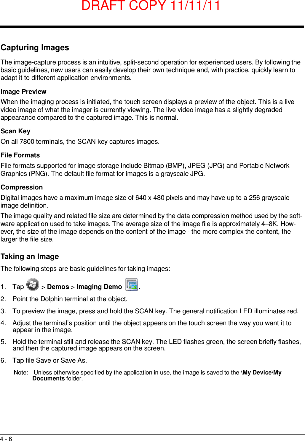
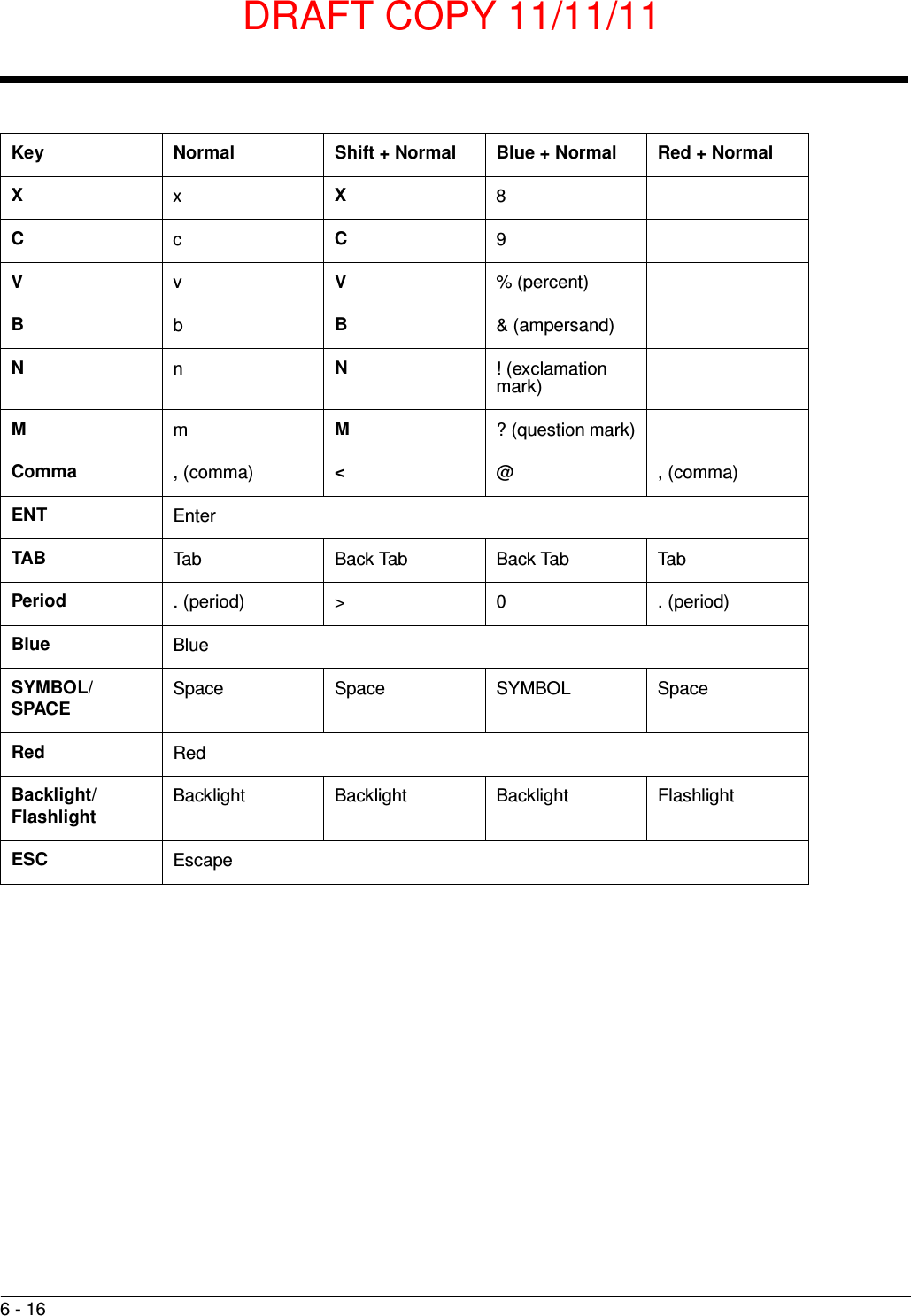
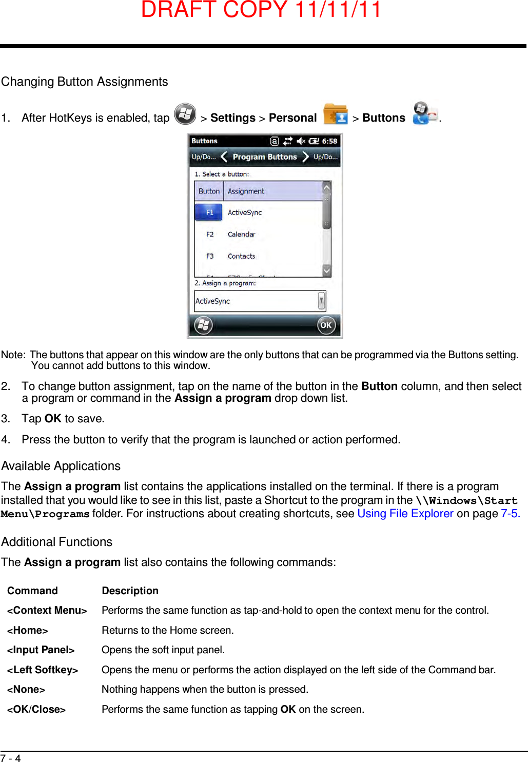
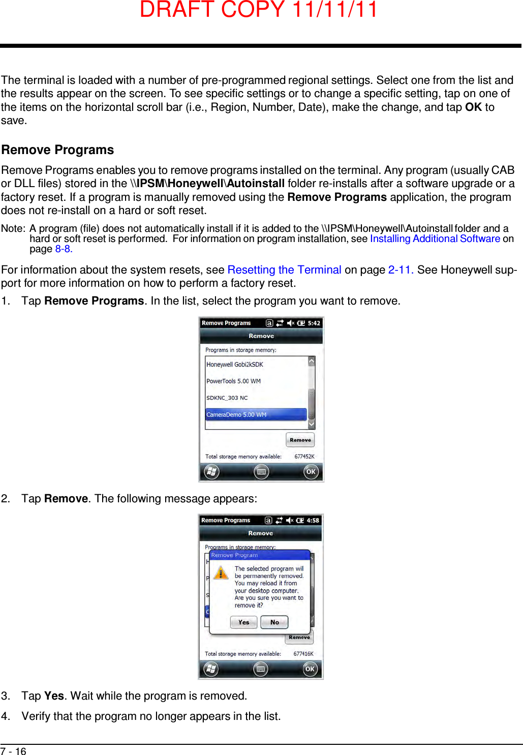
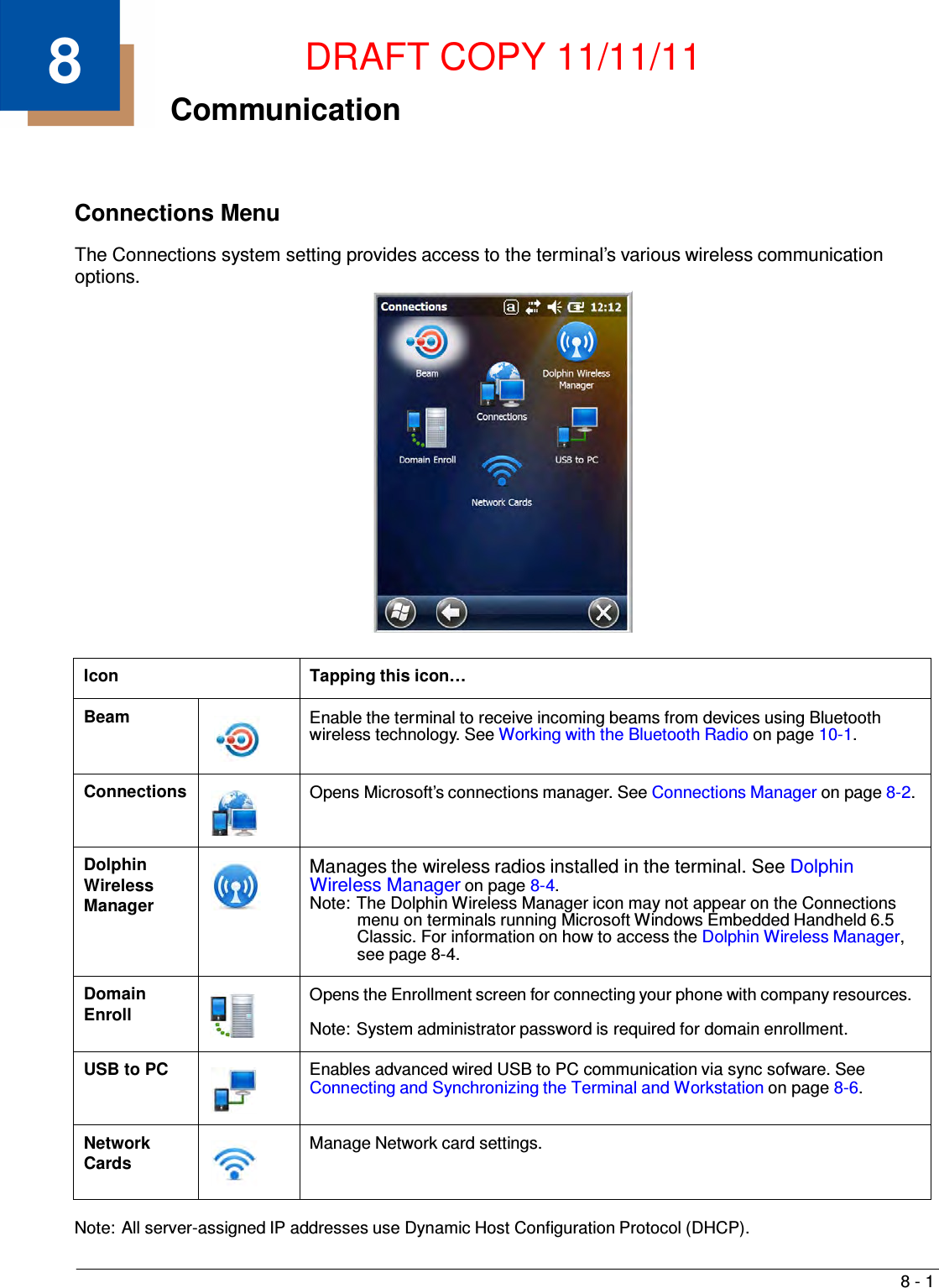
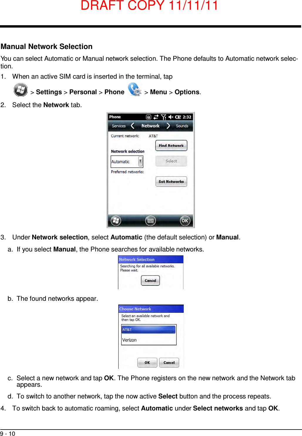
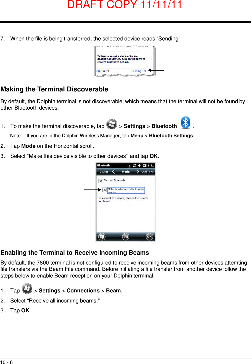
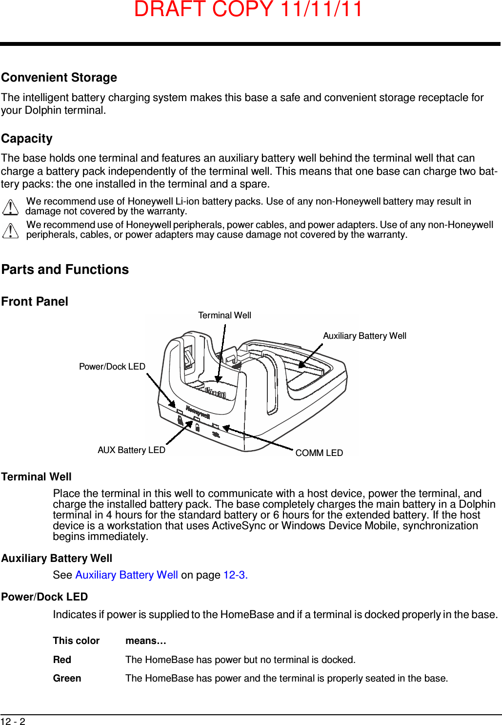
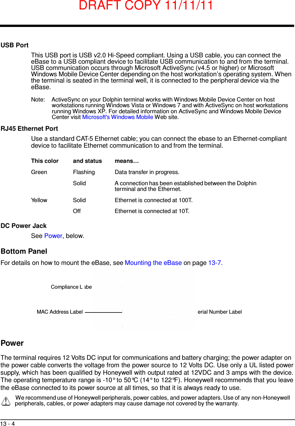
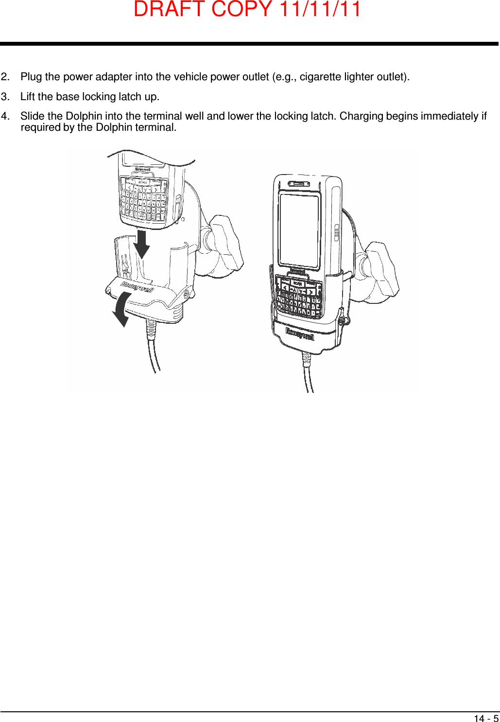
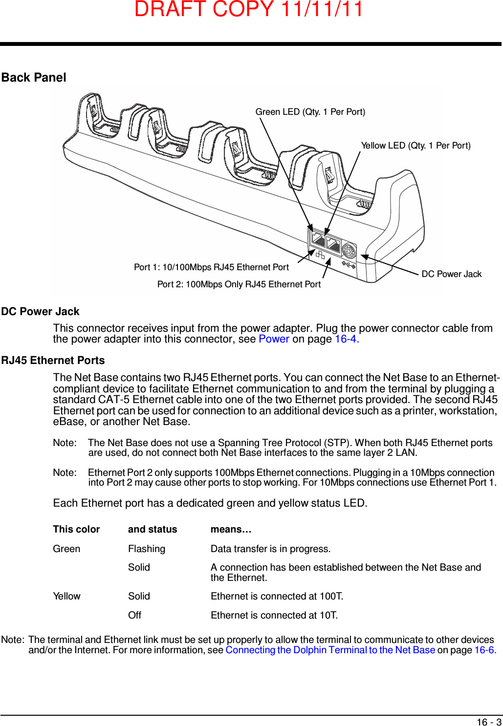
![DRAFT COPY 11/11/11 3 - 14 Internal Backup Battery Located inside the terminal is a 3.6 Volt nickel metal hydride (NiMH) backup battery. The backup battery prevents the terminal from being reset if you need to replace the main battery pack. It retains RAM data during the battery pack exchange. A fully charged backup battery provides 5 minutes of data backup time. Note: A fully charged backup battery preserves RTC content for approximately 168 hours when the terminal is in suspend mode and the main battery is not installed or completely depleted of charge. If at any time the backup battery becomes fully discharged of power (e.g., the terminal is left without the main battery pack for more than 5 minutes), the terminal resets when power is supplied. All files are retained, but you may need to restart any running applications. In addition, a fully discharged backup battery requires a minimum of 24 hours of charging time to reach a full charge. Note: Data and programs stored in Flash memory are not lost even if the internal backup battery fails. Charging The internal backup battery is powered by the main battery pack. Therefore, charging the internal battery requires a charged main battery pack be installed in the terminal and the terminal be connected to a charging device. The internal backup battery must be fully charged before using the terminal for the first time. Honeywell recommends charging the Dolphin terminal for at least 24 hours prior to initial use to ensure the internal backup battery is fully charged. After that, if the internal backup battery becomes fully discharged of power, it requires a minimum of 24 hours of charging time to function normally. Guidelines for Use Follow these guidelines to maximize the life of the internal backup battery: • Keep a charged battery pack in the terminal; the backup battery prematurely discharges if there is not at least a partially charged battery in the terminal. • Keep the terminal connected to power when the terminal is not in use. Managing Battery Power Letting the backup battery become fully discharged causes the terminal to lose all data in RAM. Honey- well recommends, you keep a charged battery pack in the terminal at all times to help prevent data loss. The internal battery discharges prematurely if there is not at least a partially charged battery in the termi- nal. When you remove a battery pack, insert another charged battery pack in the terminal immediately. Default Critical and Low Battery Points When the terminal is running on battery power (as opposed to external power), warnings are displayed when the battery reaches critical and low battery points. The warning points are determined by the fol- lowing registry entry: [HKEY_LOCAL_MACHINE\ControlPanel\Power] There are two DWORD values in this registry entry: MedState and LowState. The default values for these entries are as follows:](https://usermanual.wiki/Honeywell/7800LW.user-manual/User-Guide-1582941-Page-42.png)
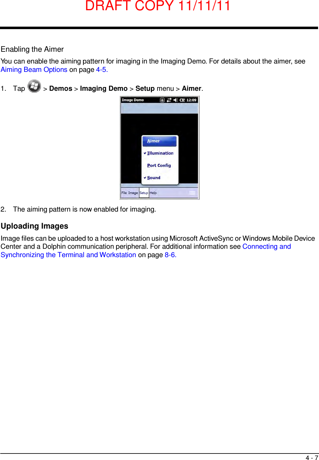


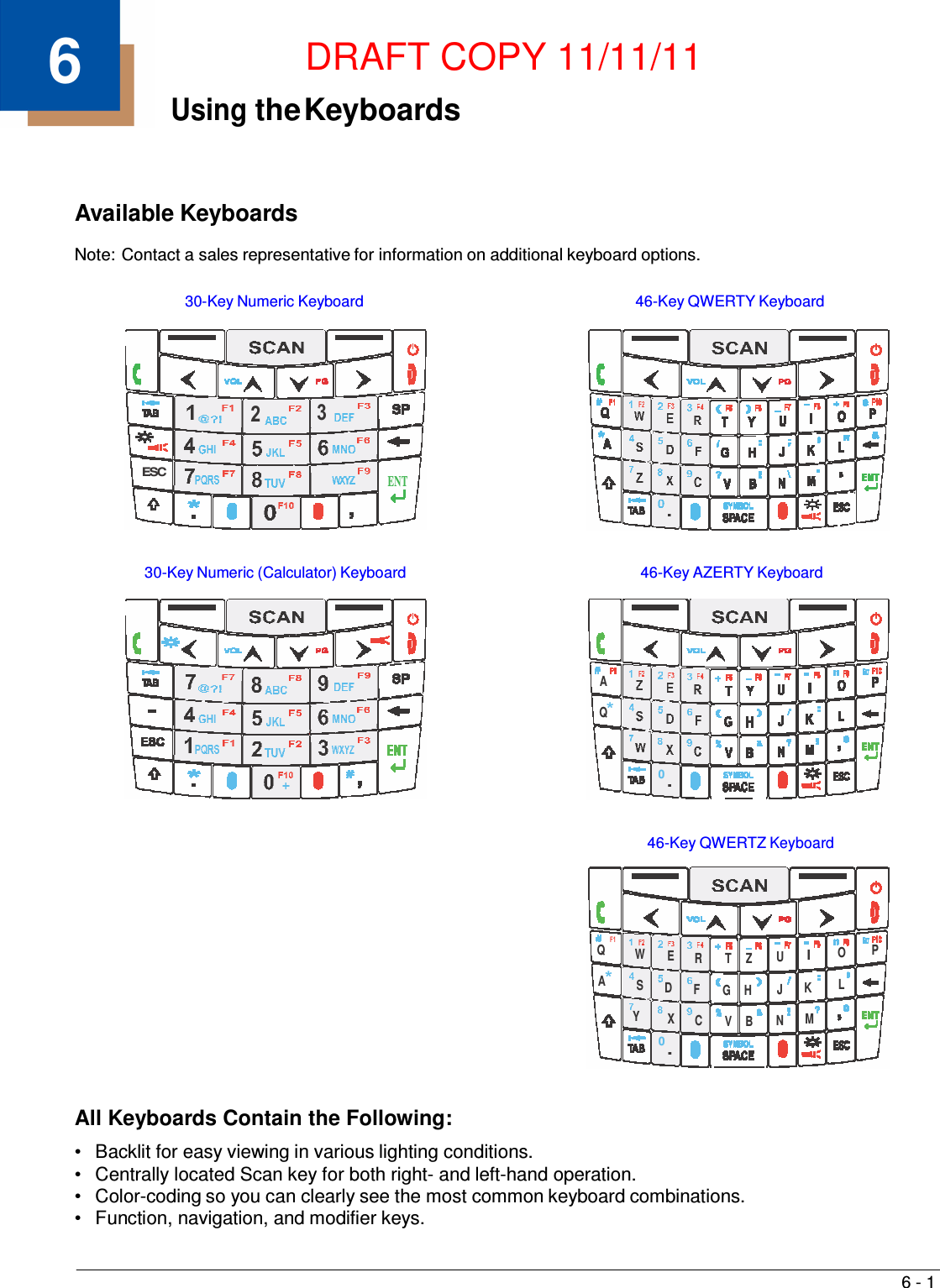
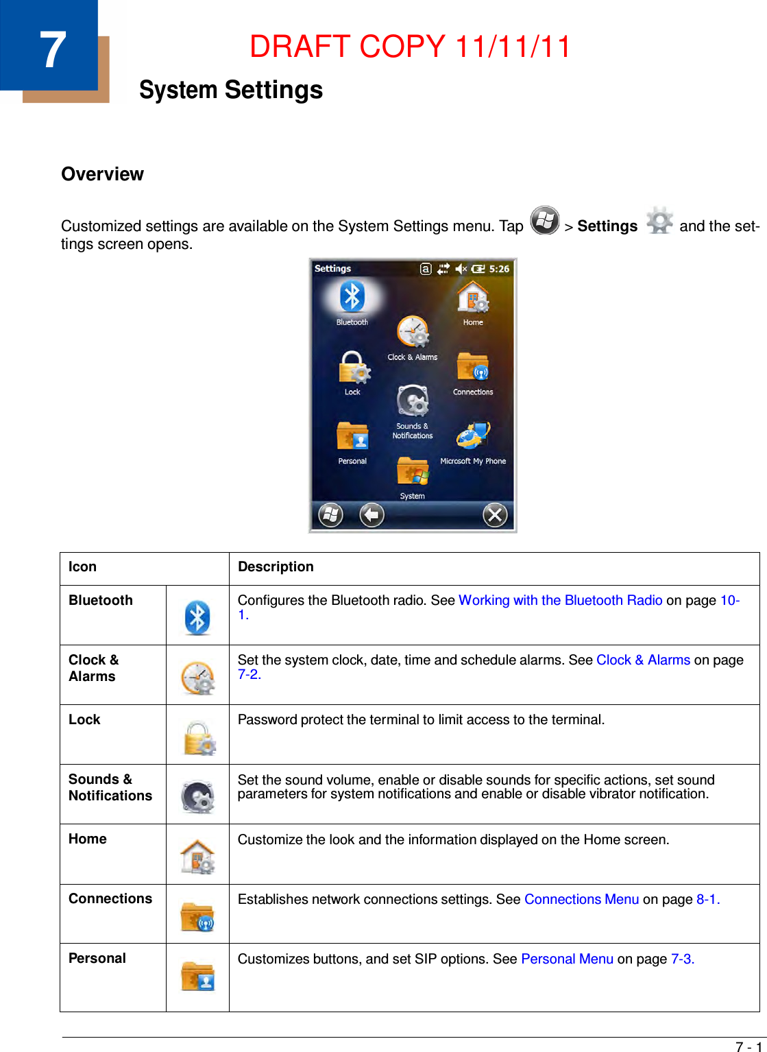
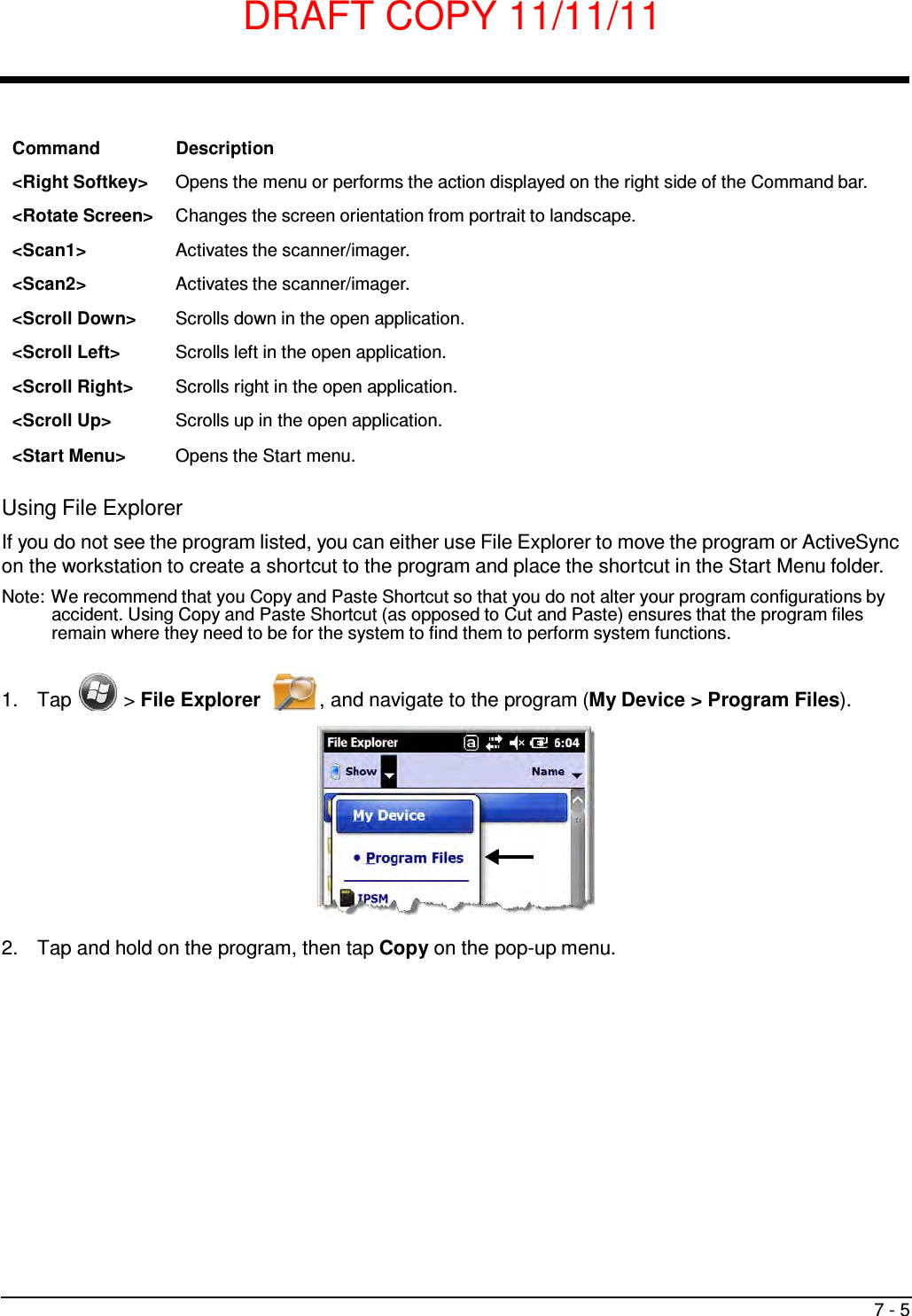
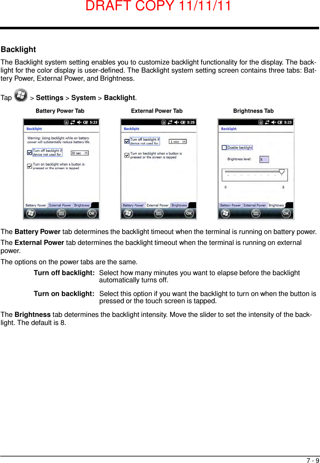
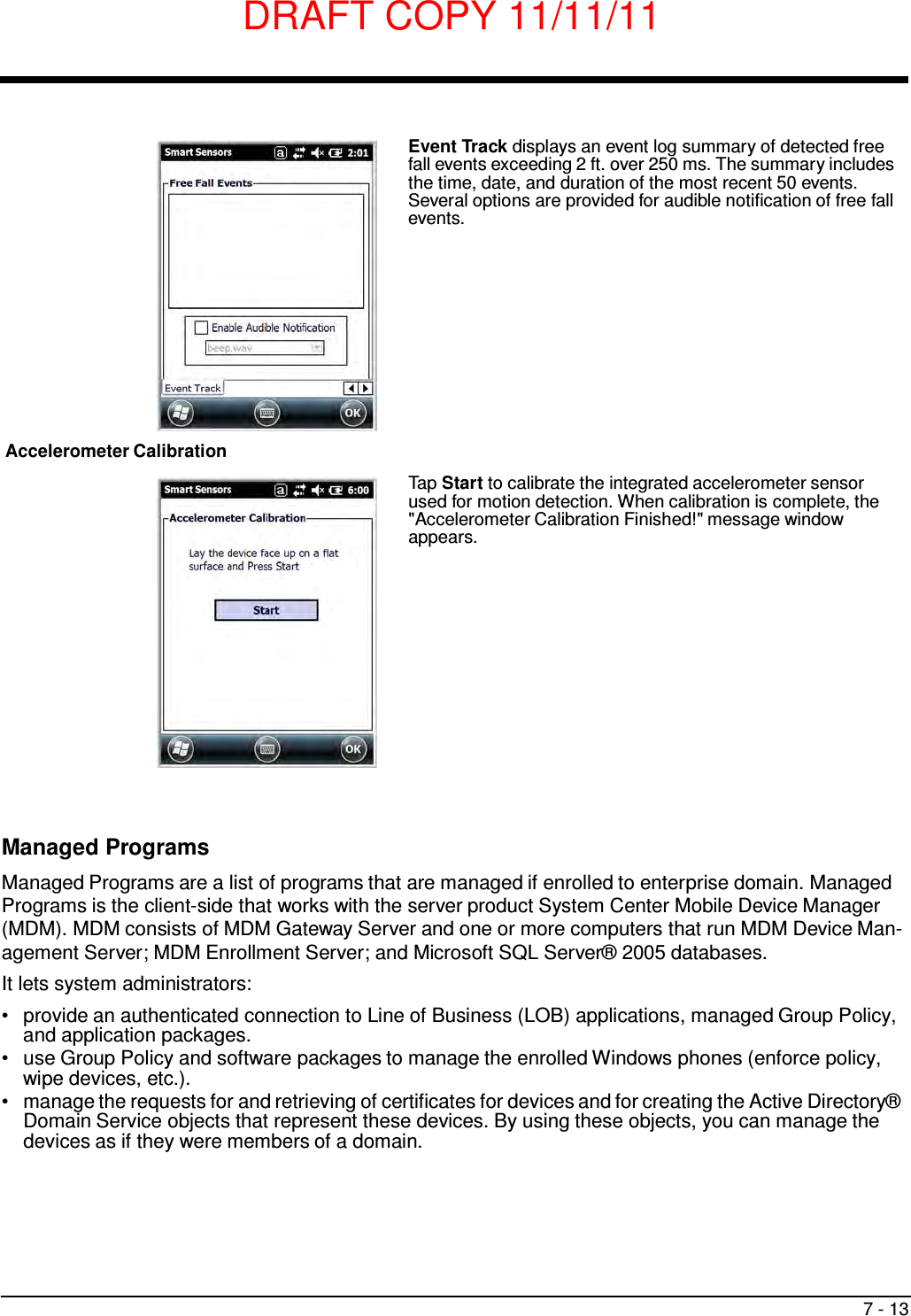
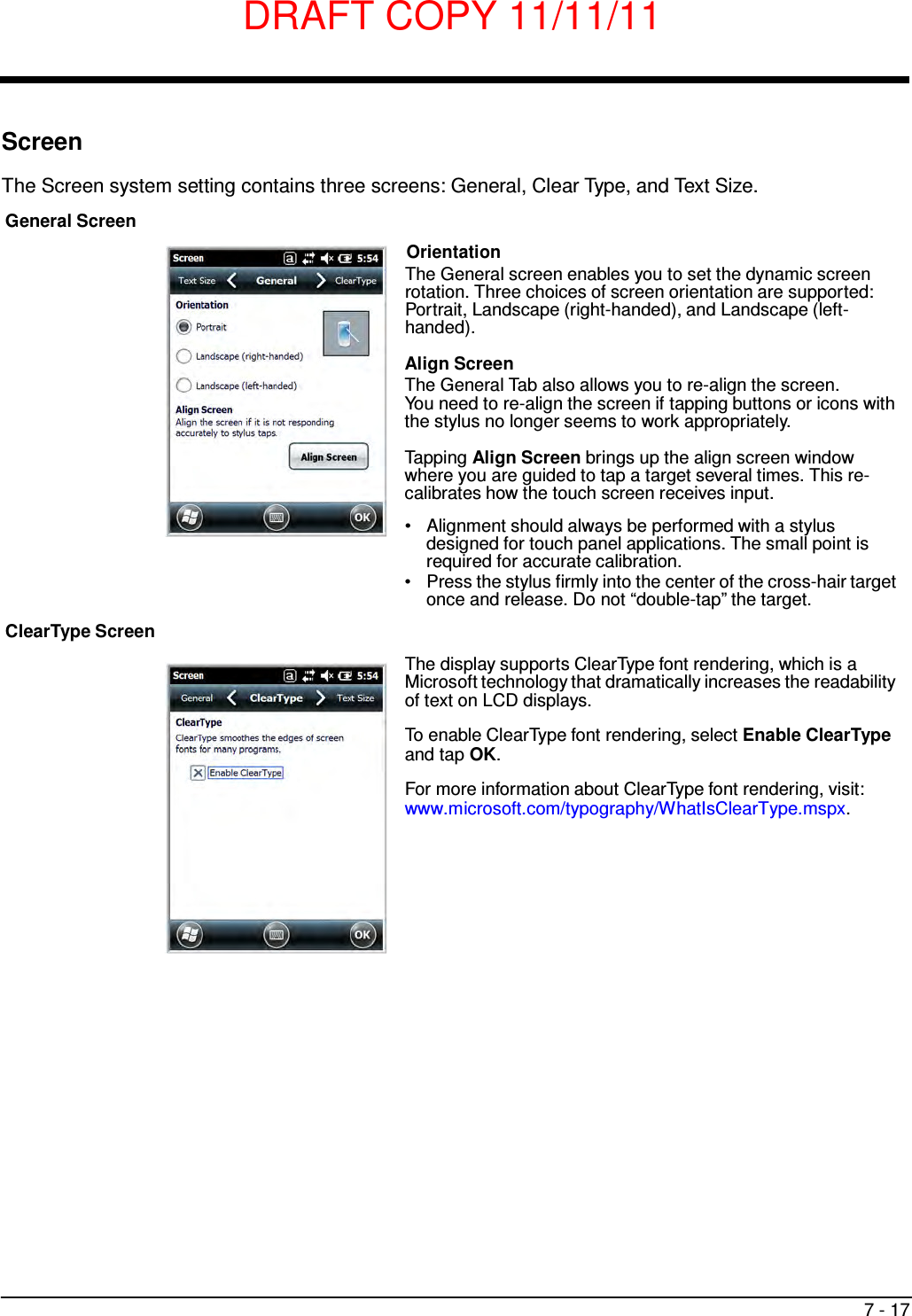

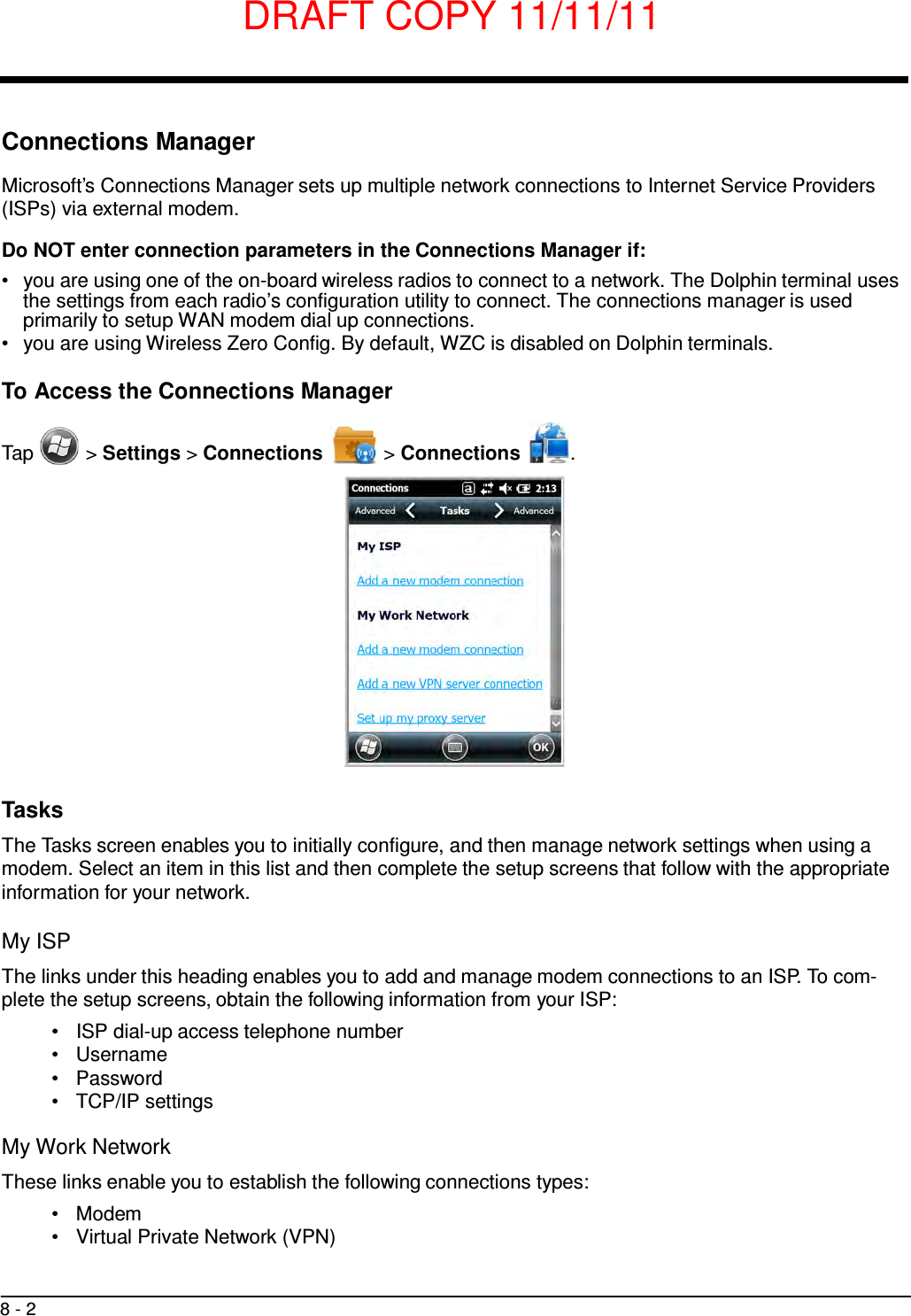
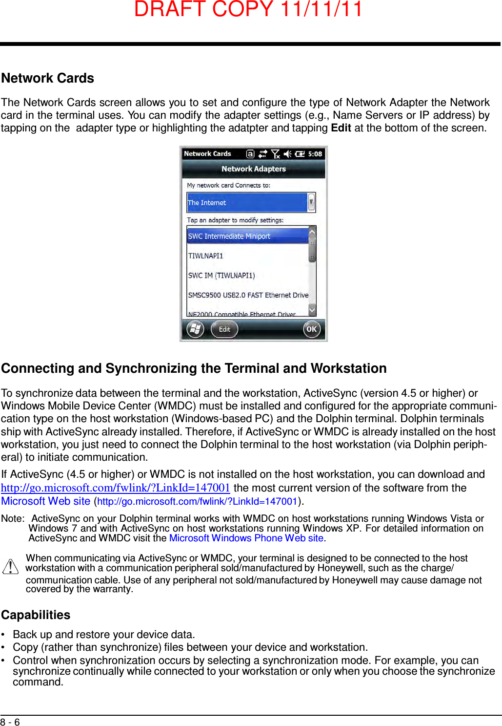
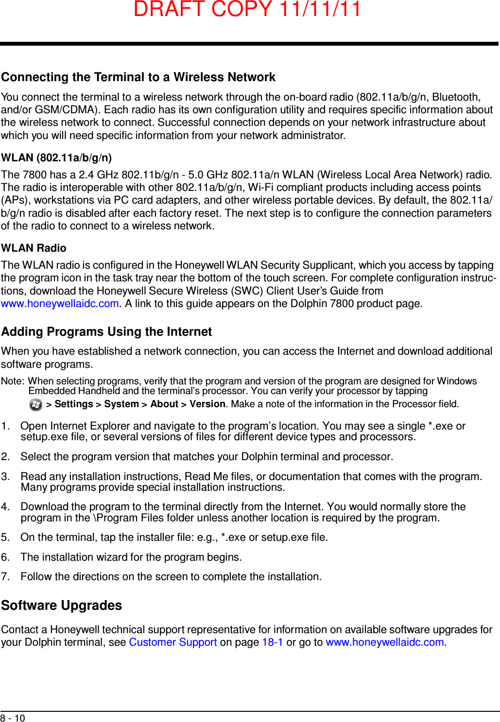

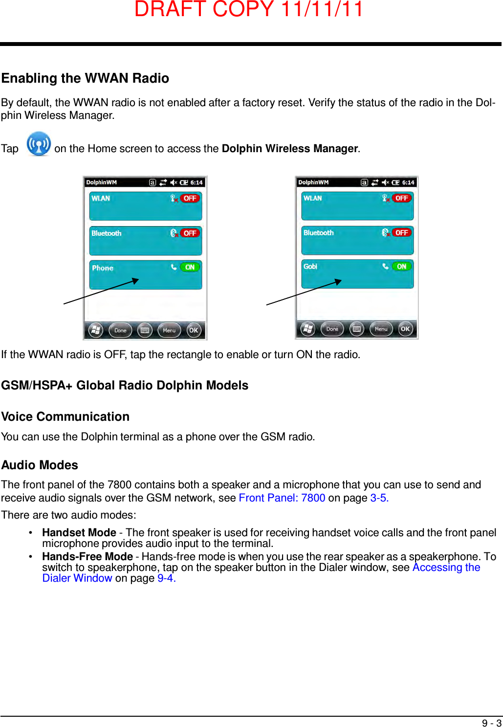
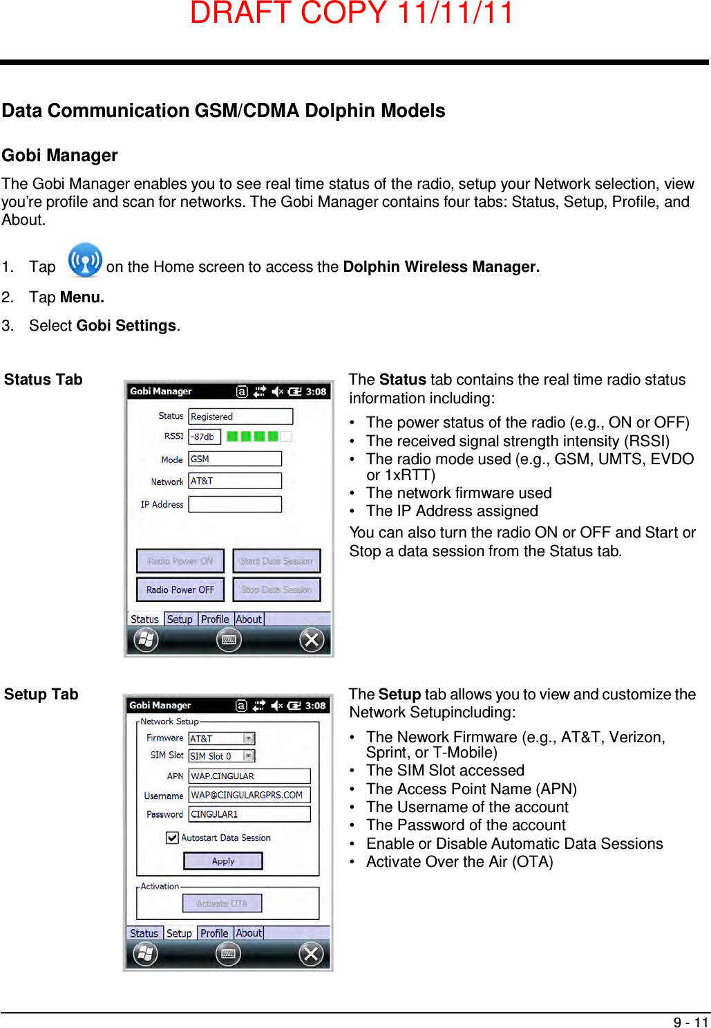


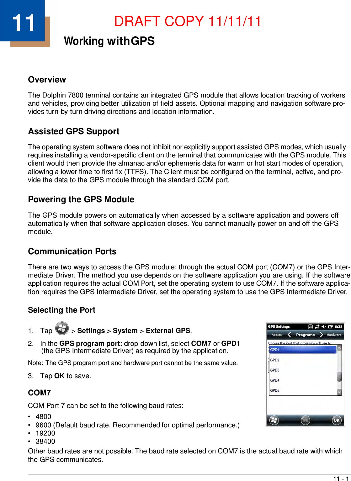
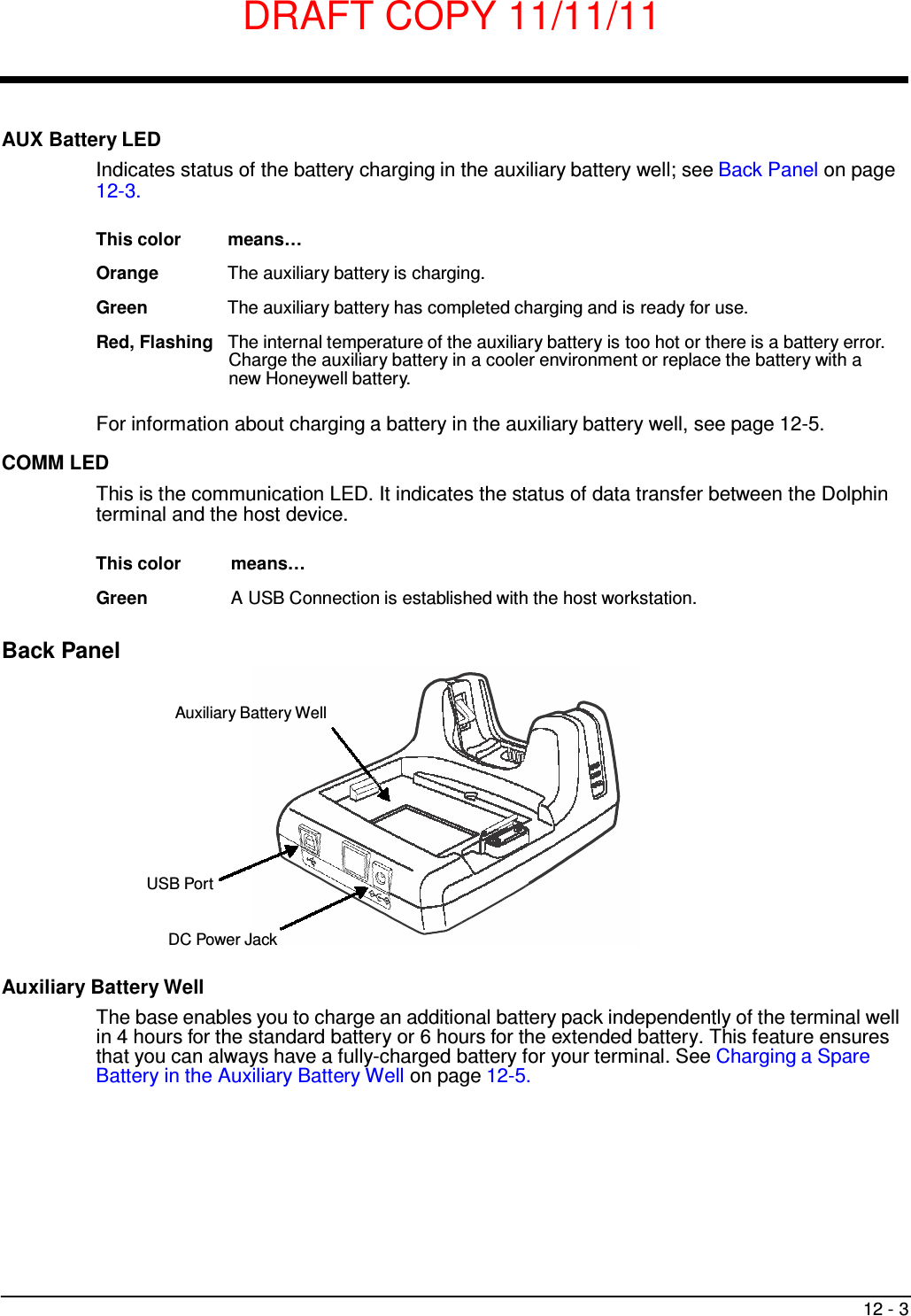
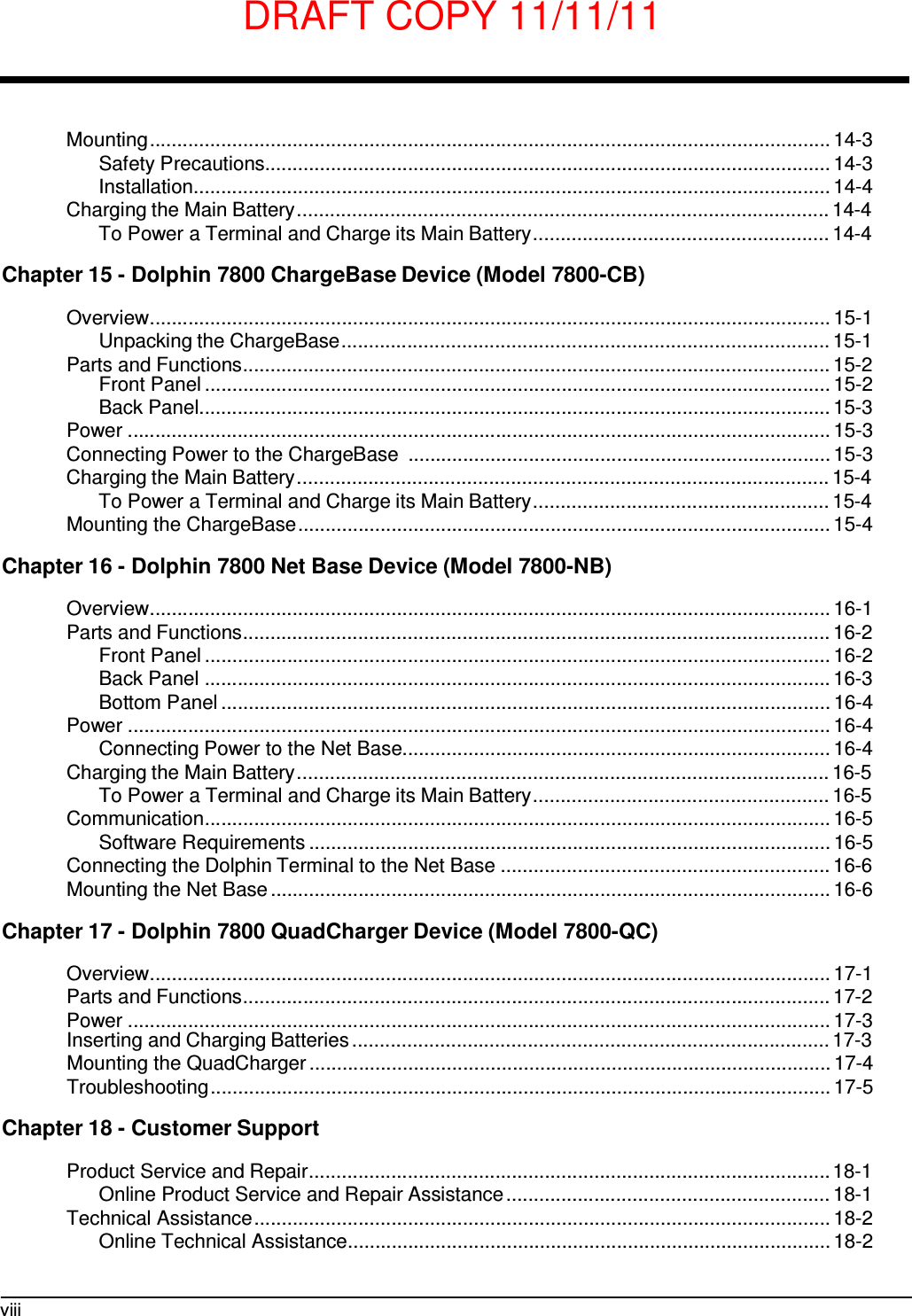
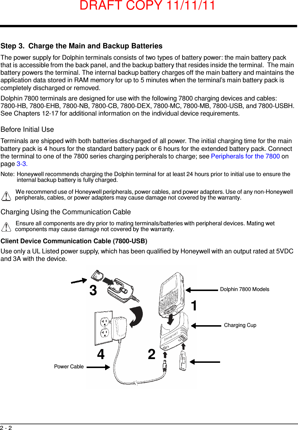
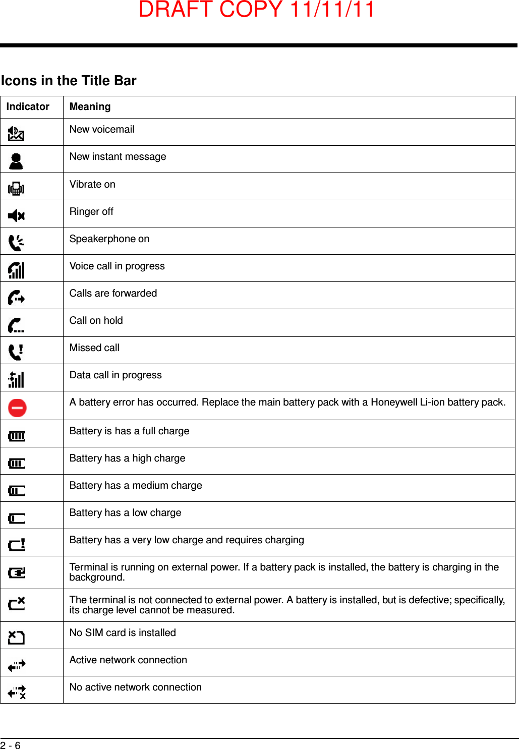
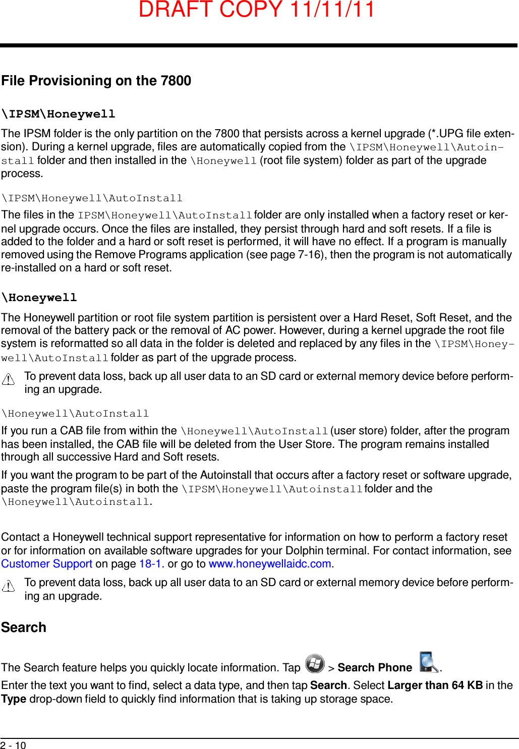
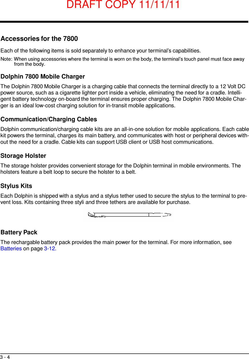
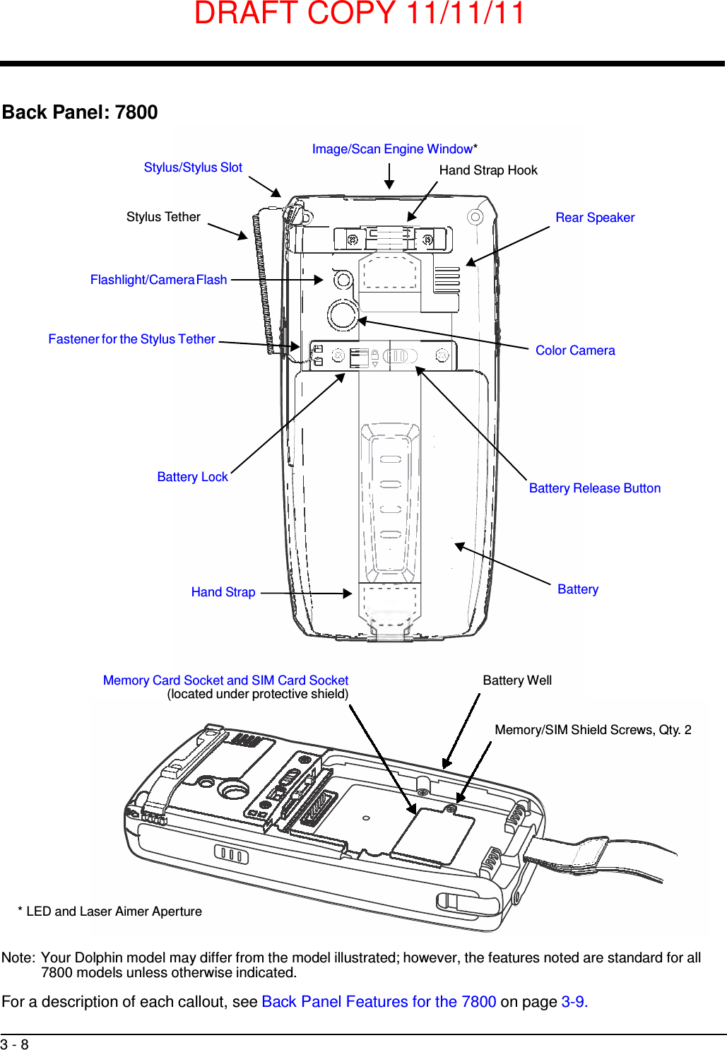
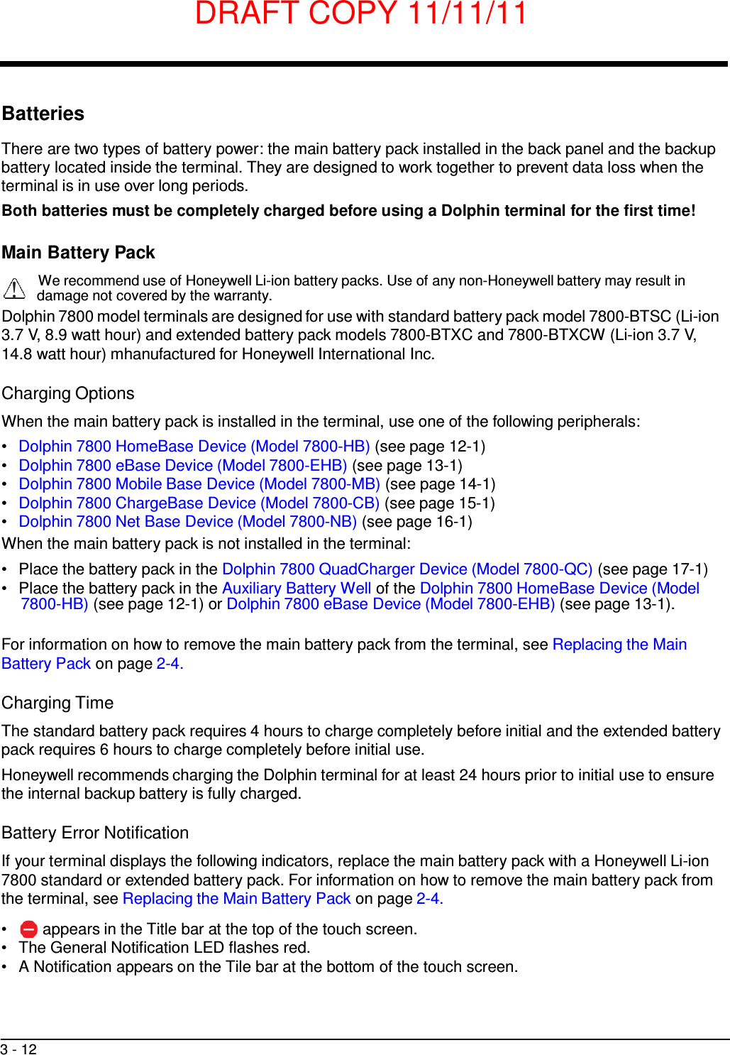
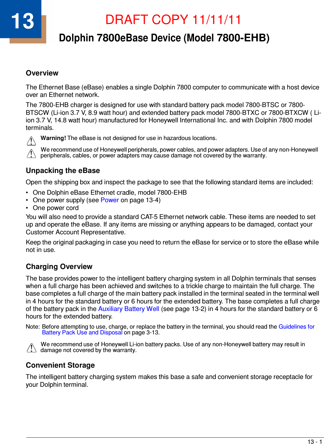
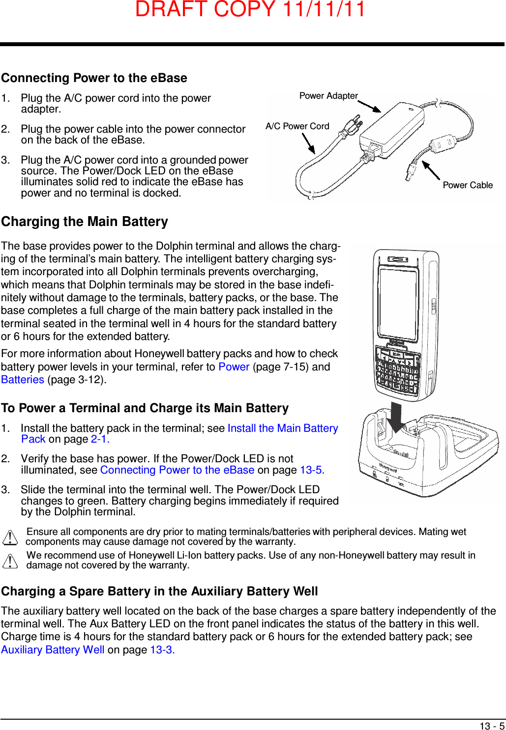
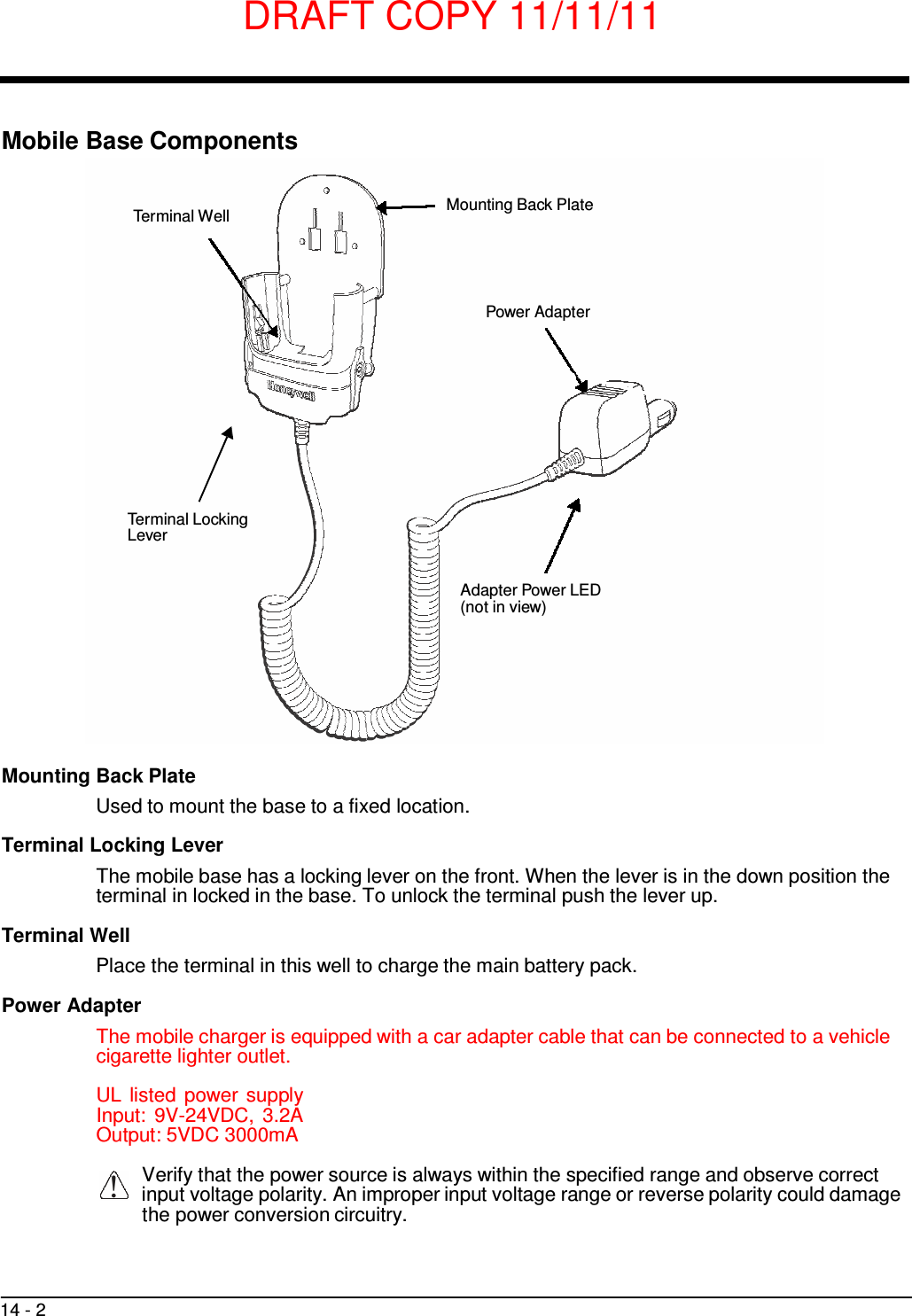
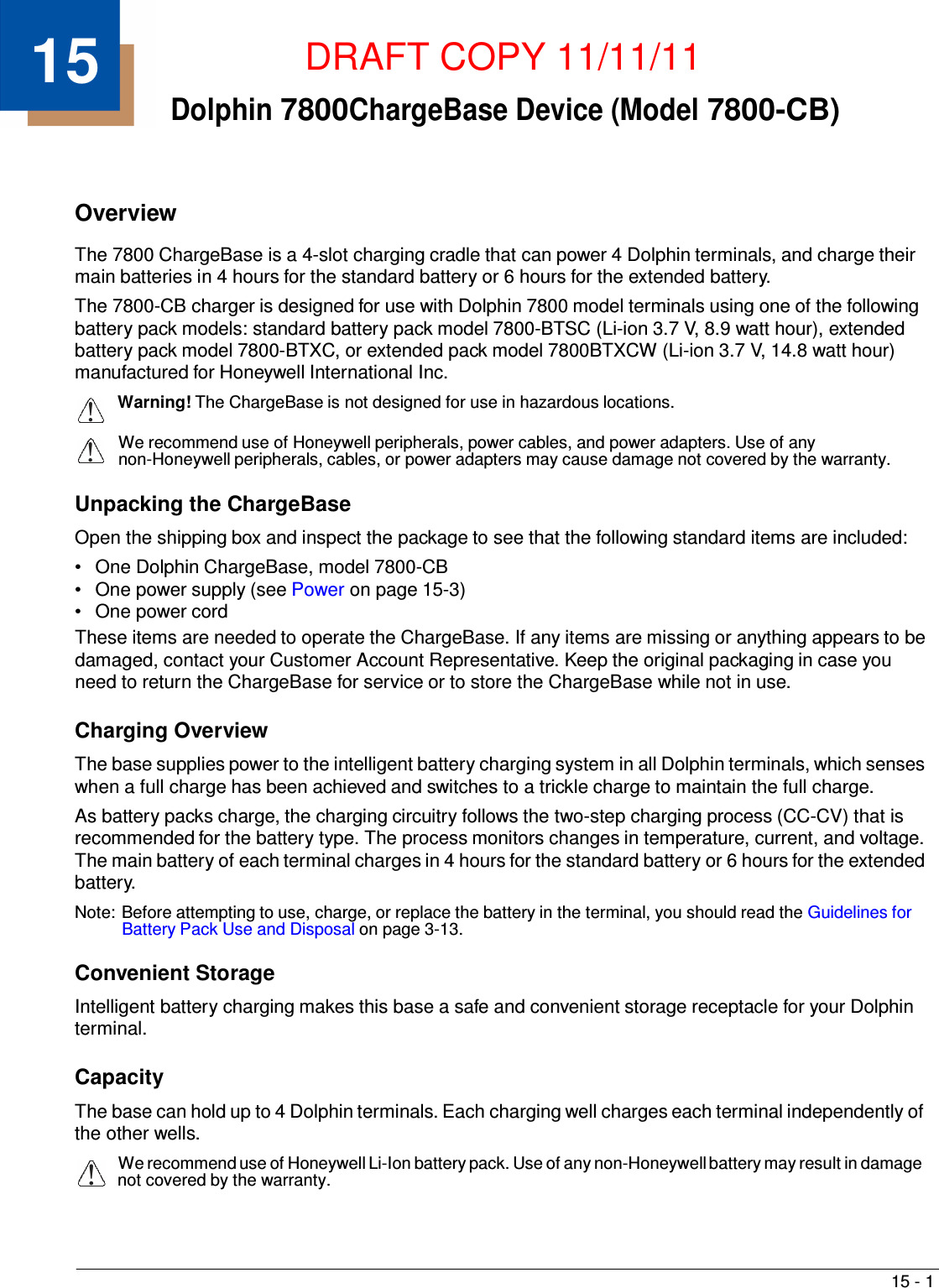
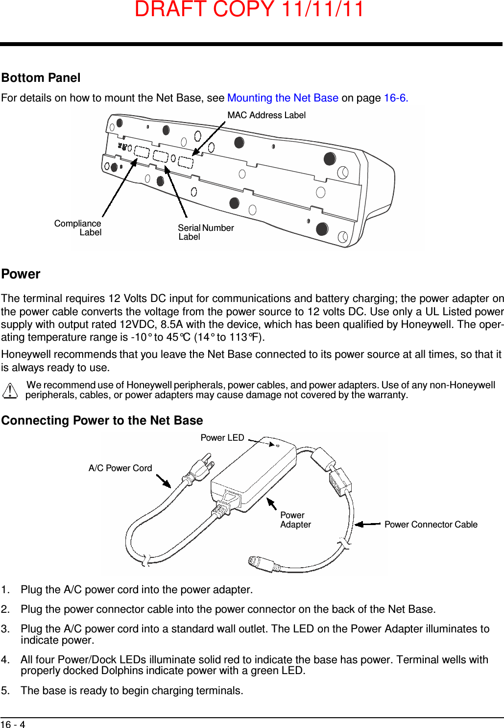
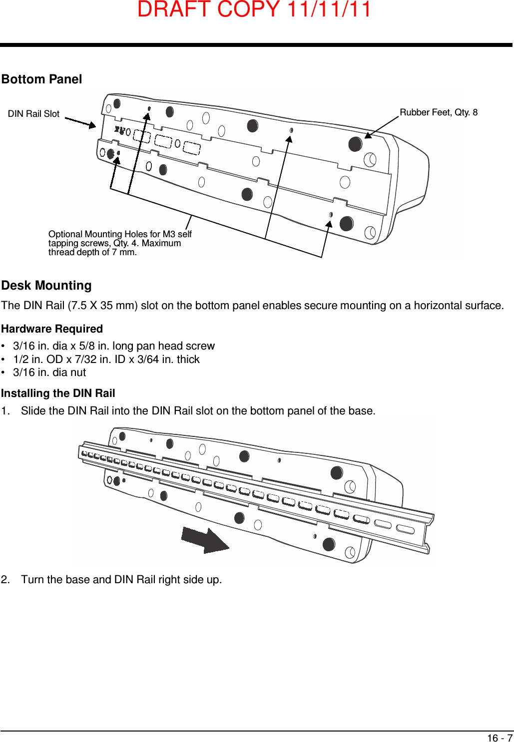
![DRAFT COPY 11/11/11 12 - 7 Mounting the HomeBase Set the base on a dry, stable surface, such as a desktop or workbench near an electrical outlet. Be sure to provide enough workspace with good lighting for the user to view and operate the Dolphin terminal while it is in the base. When choosing a mounting location, bear in mind that the location must allow users' easy access to the Auxiliary Battery Well and the back panel of the HomeBase where the USB port and the power jack are located. Optional Hardware Mount On the bottom of the HomeBase there are four mounting holes with a maximum depth of 7 mm that can be used to secure the base to a horizontal surface such as a desktop or workbench using M3 self tap- ping screws. Optional Mounting Holes for M3 self tapping screws, Qty. 4. Maximum thread depth of 7 mm. 101 mm [3.98 in.] 98 mm [3.86 in.] CL 90 mm [3.54 in.]](https://usermanual.wiki/Honeywell/7800LW.user-manual/User-Guide-1582941-Page-135.png)

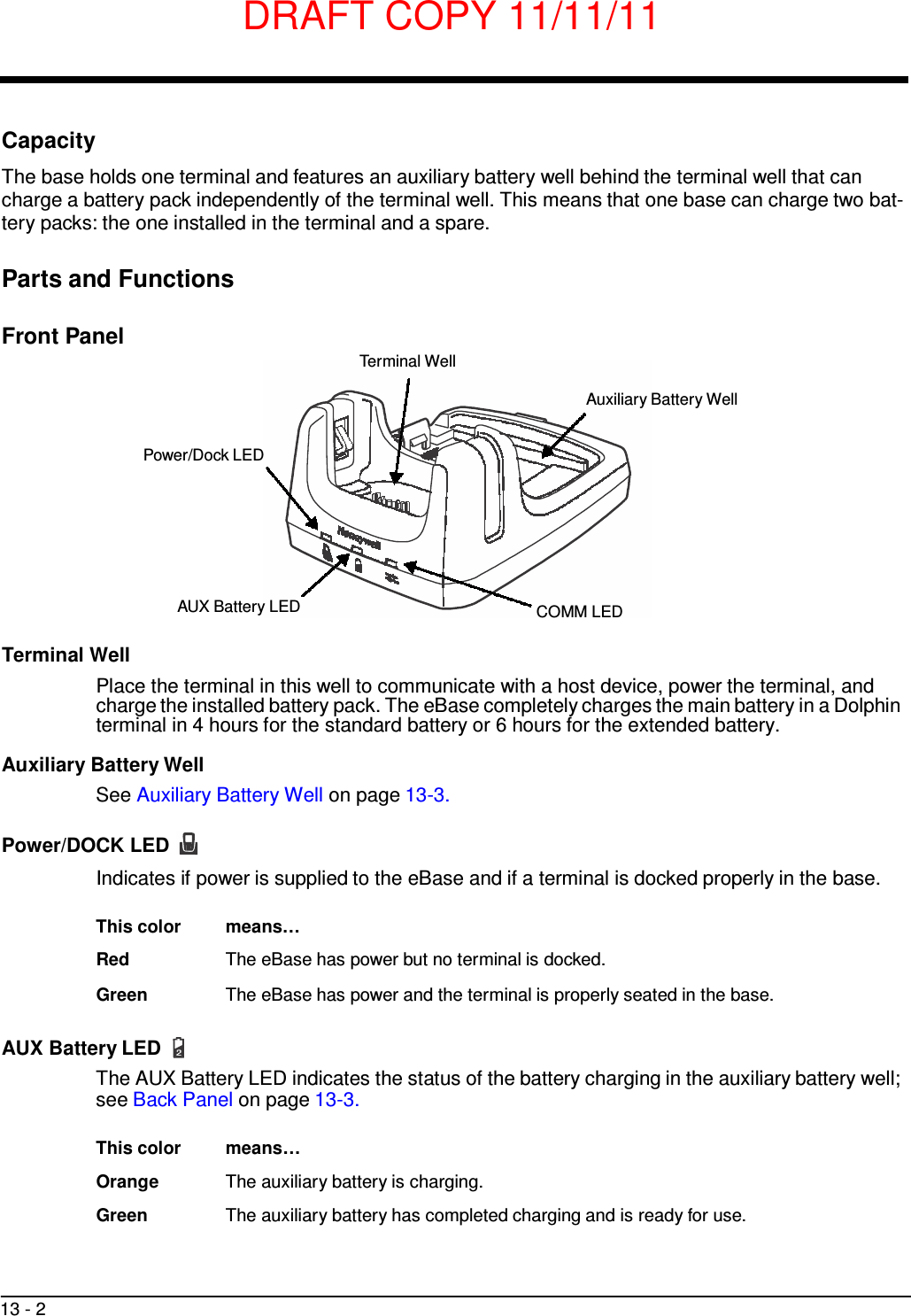
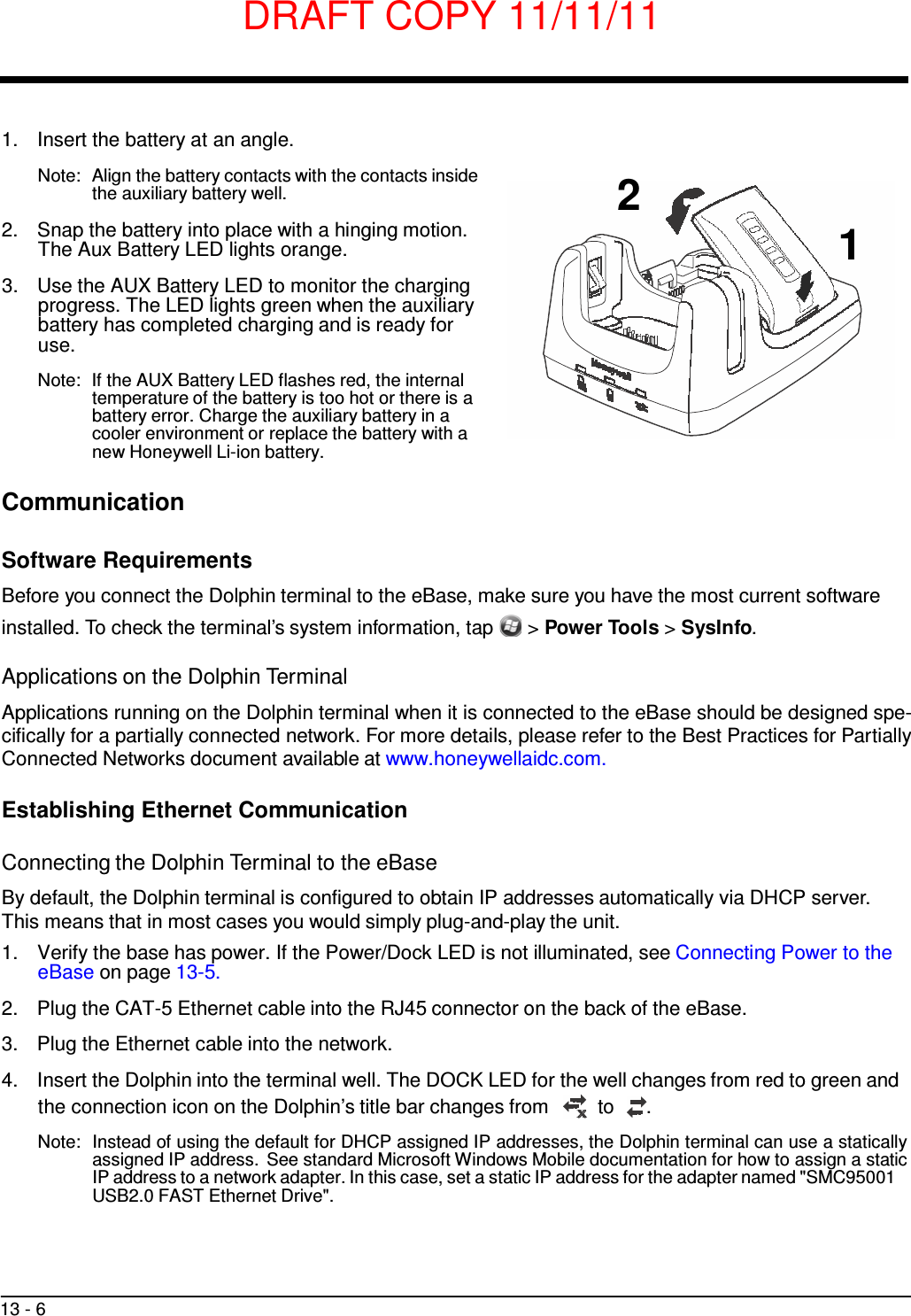
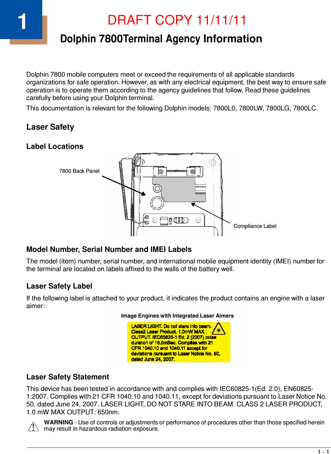
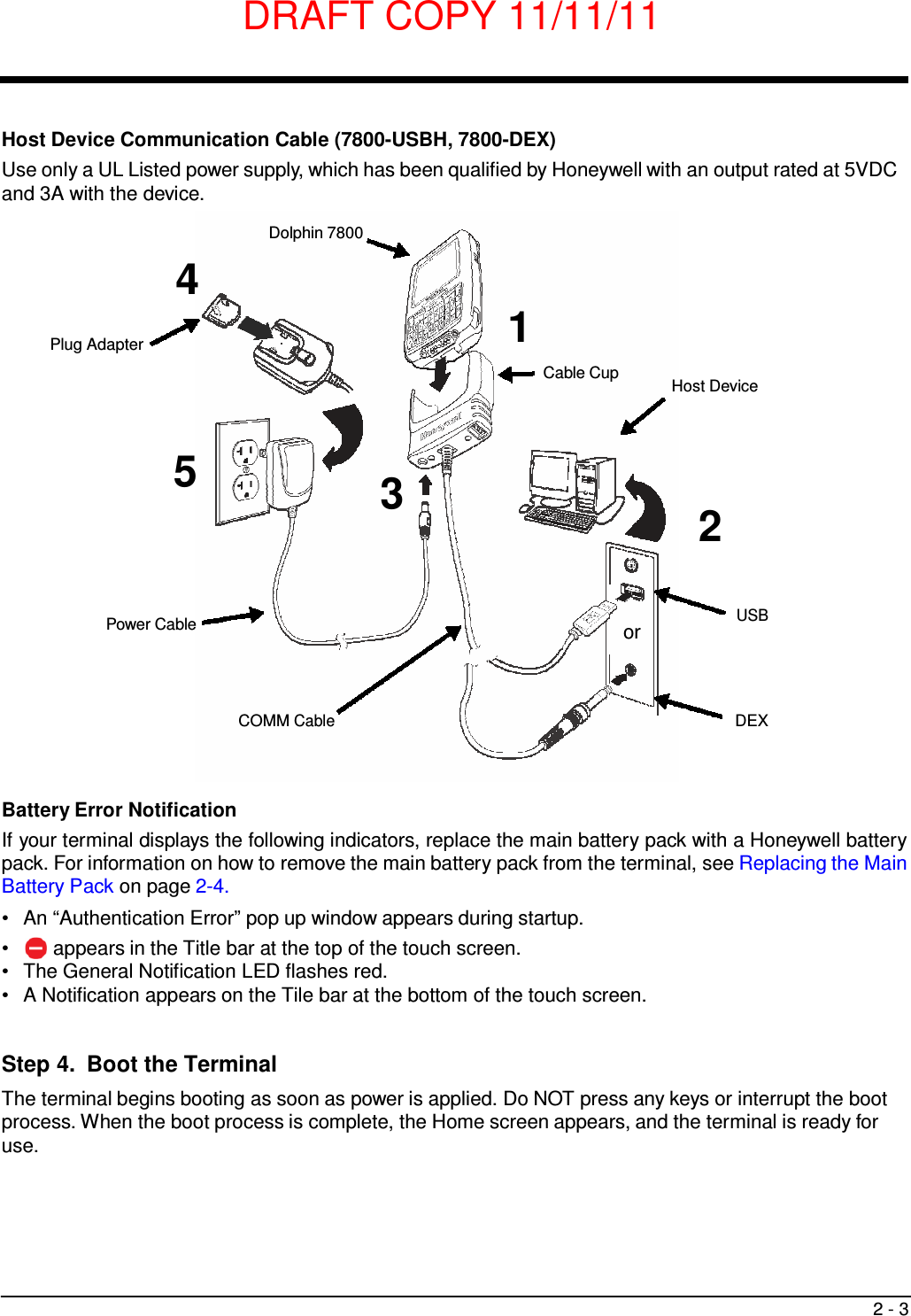
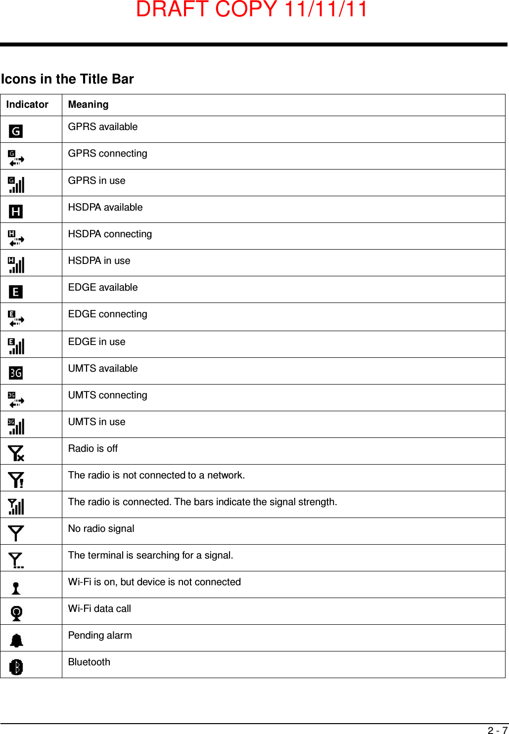
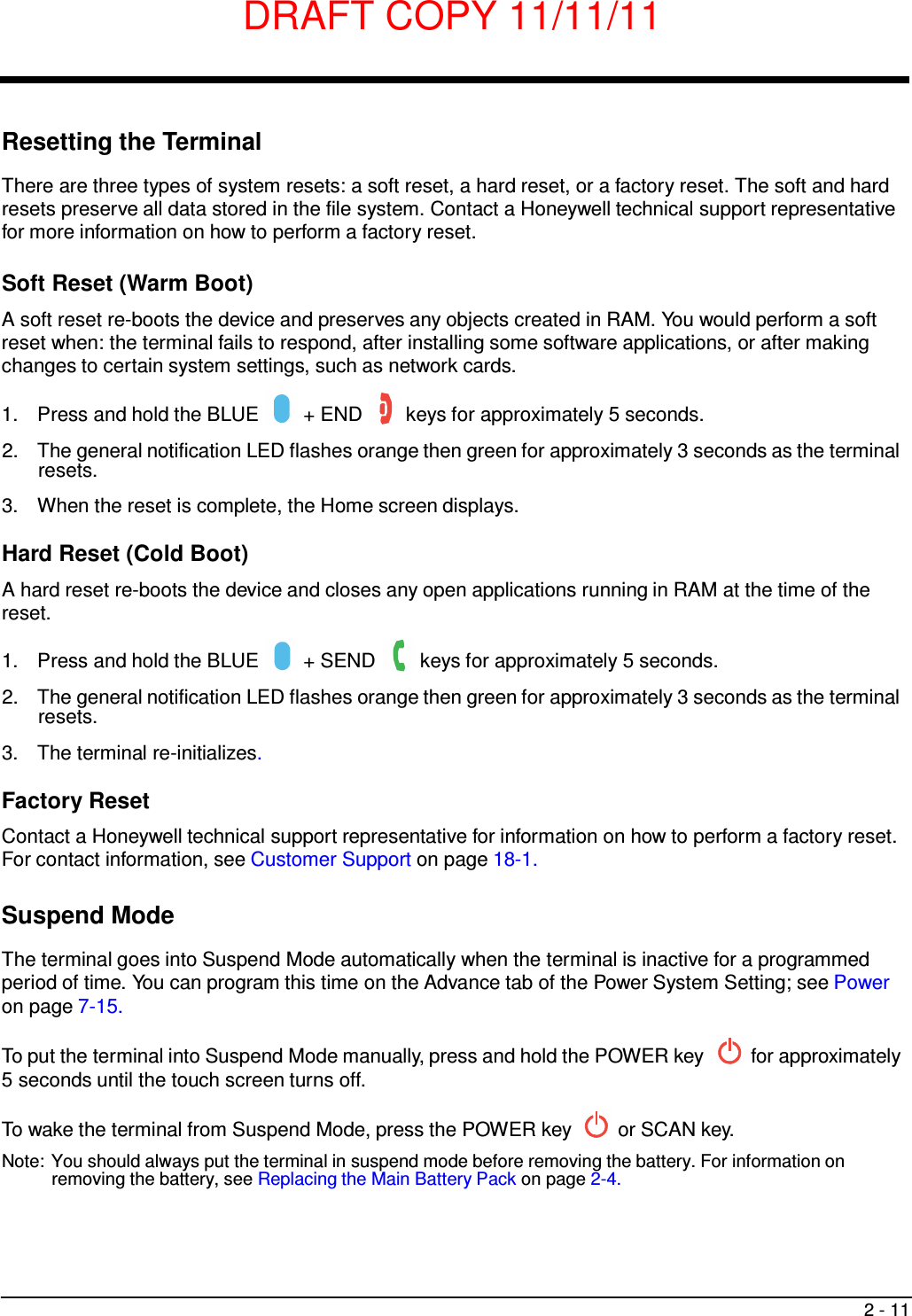
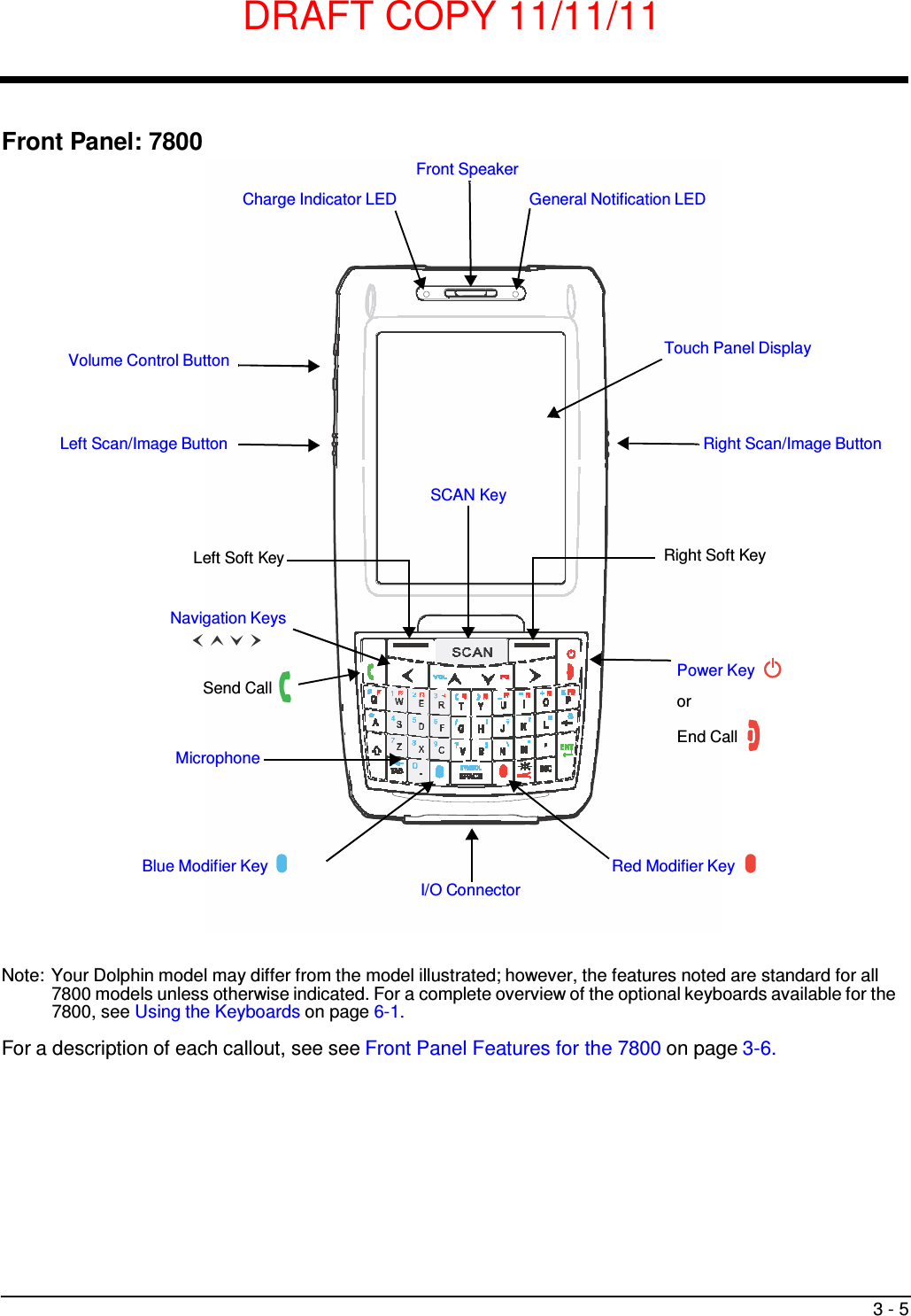
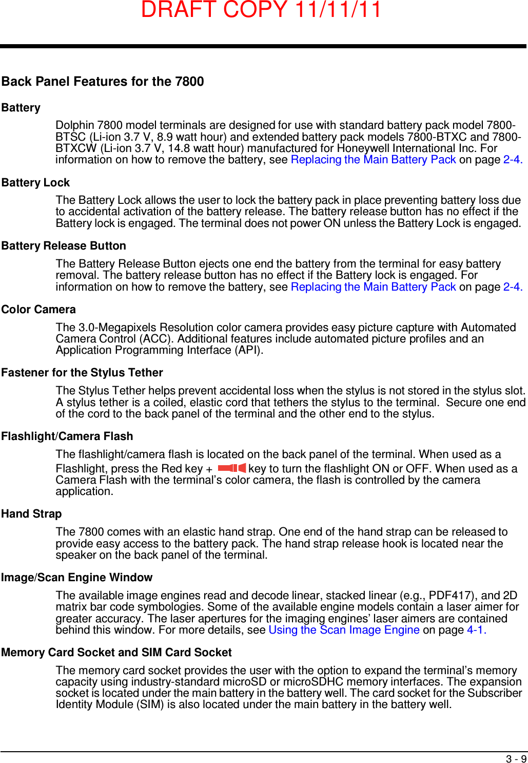
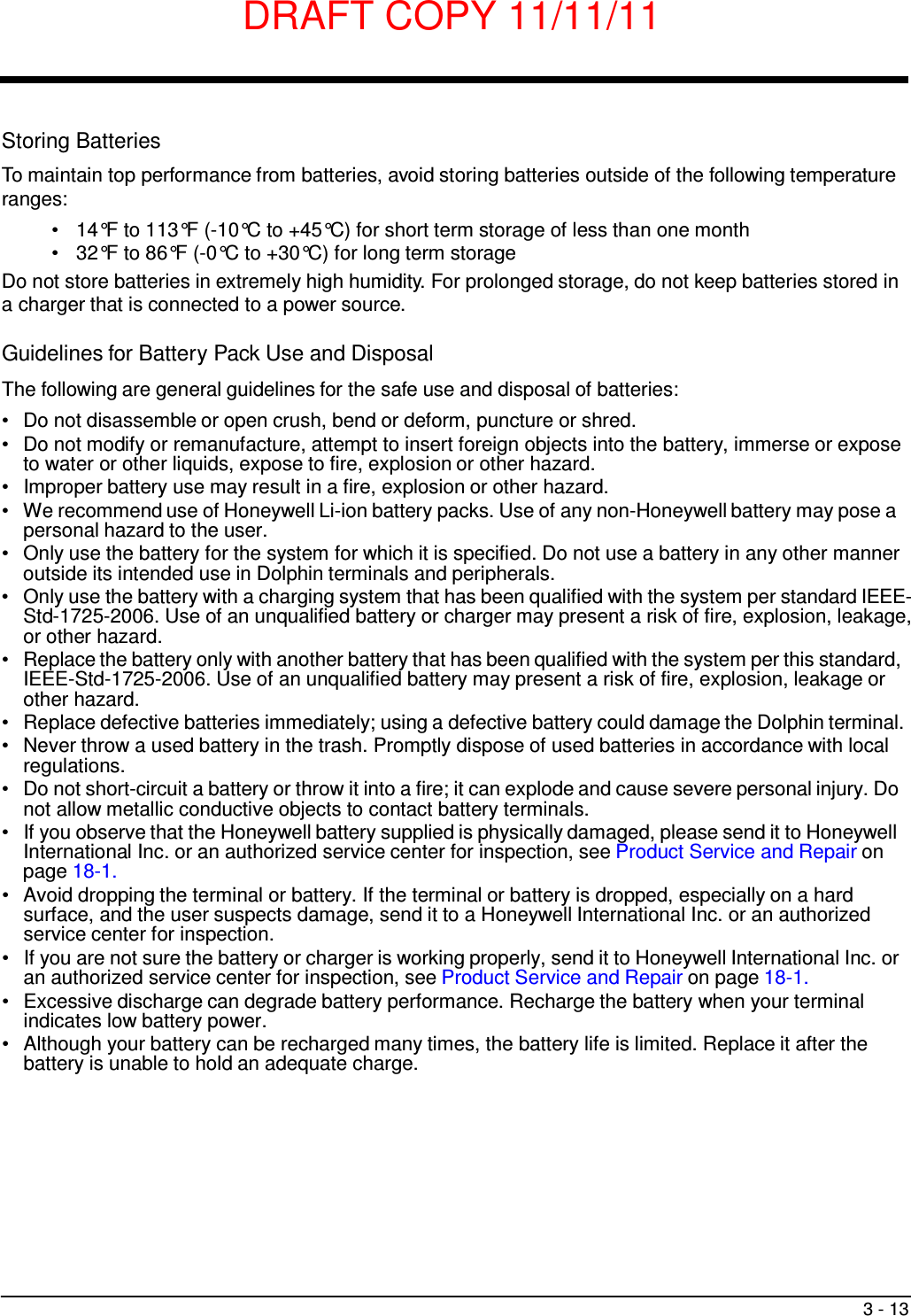
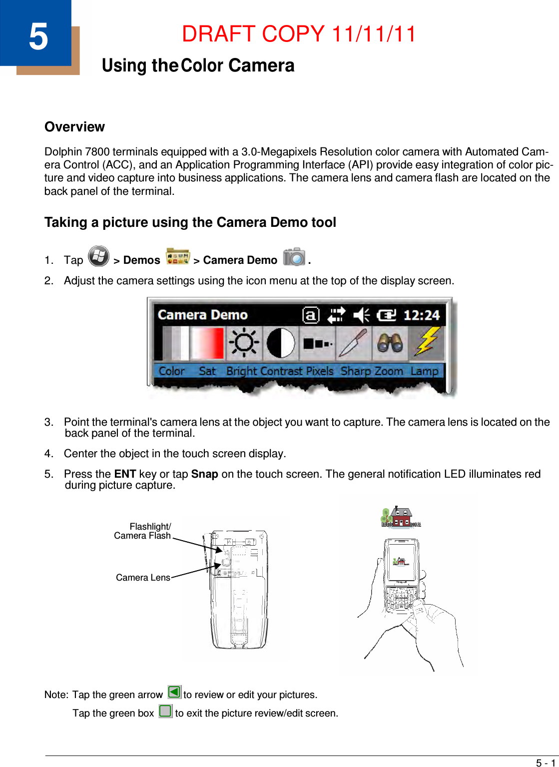
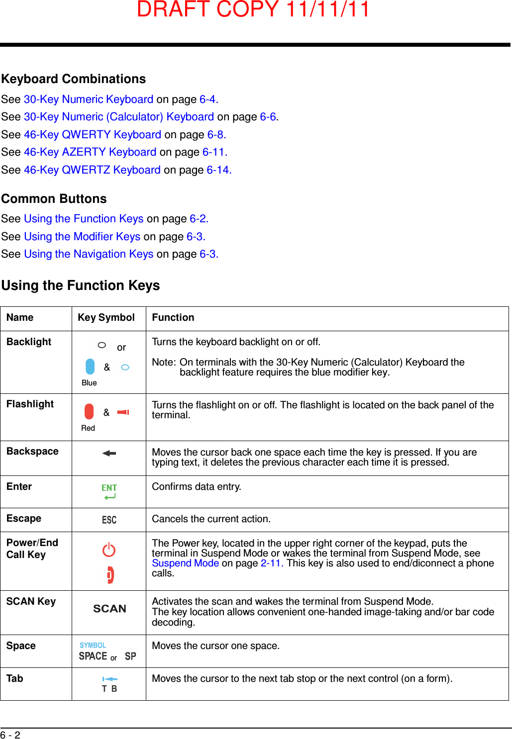
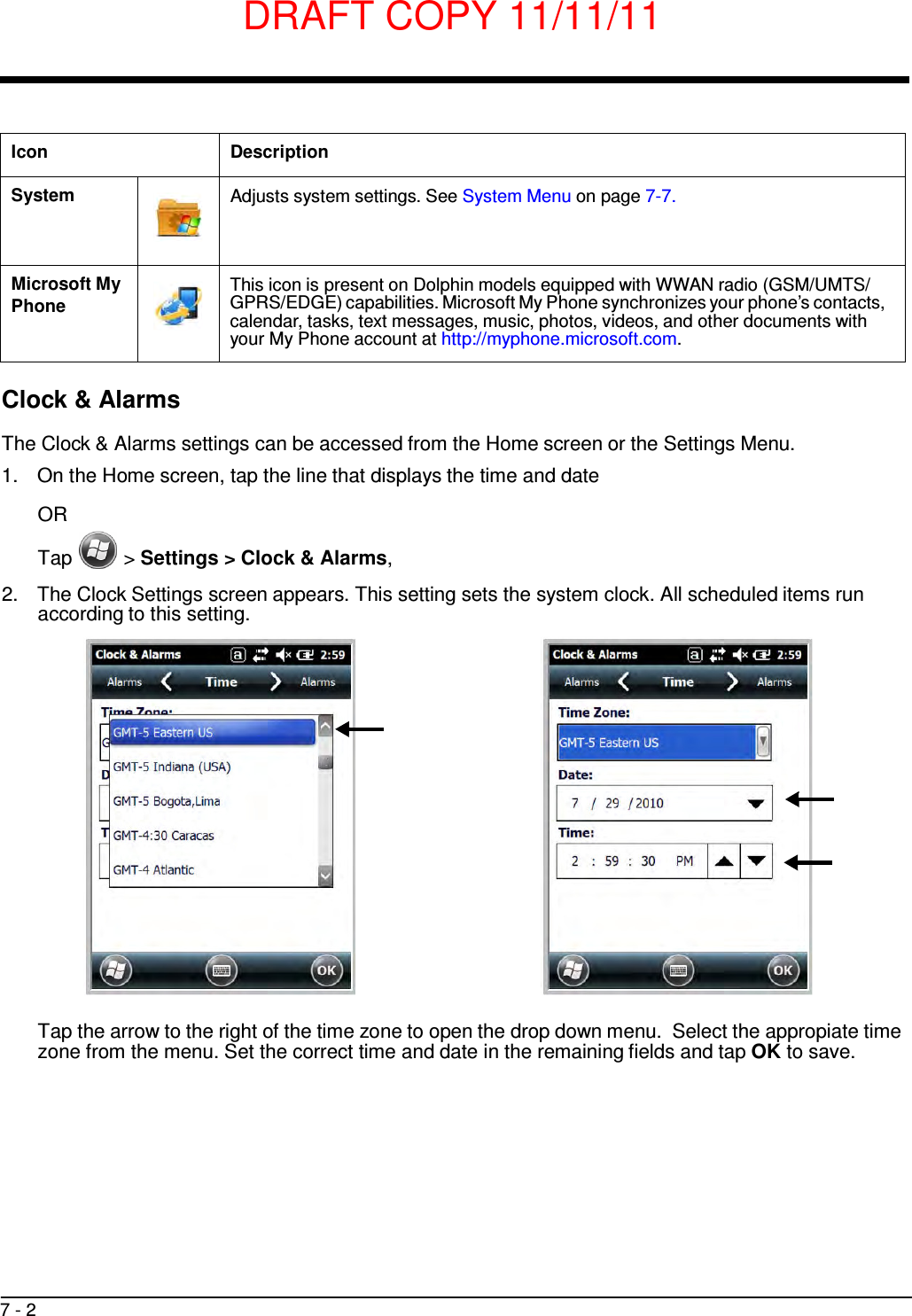
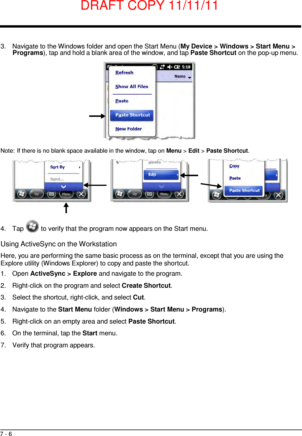
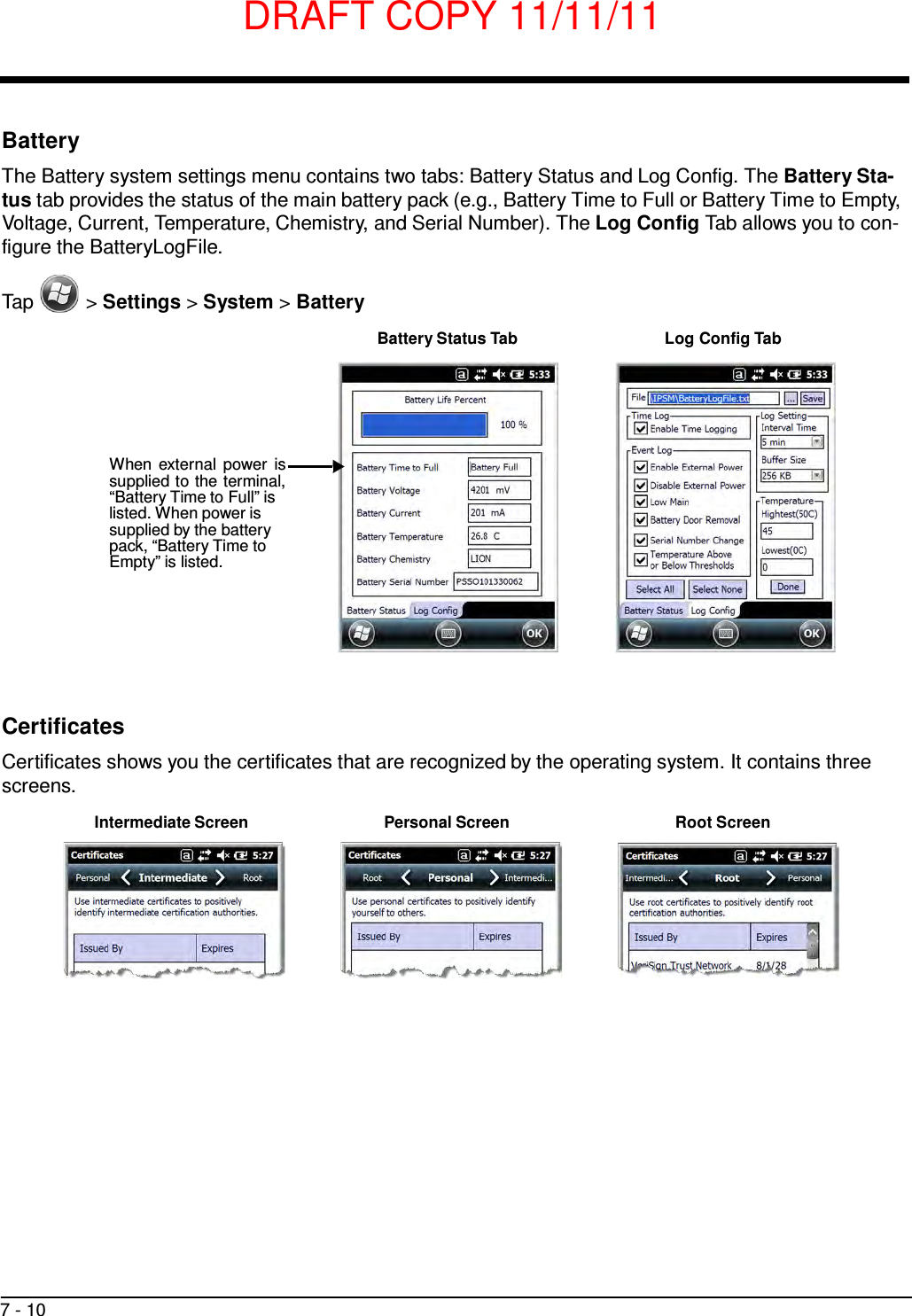
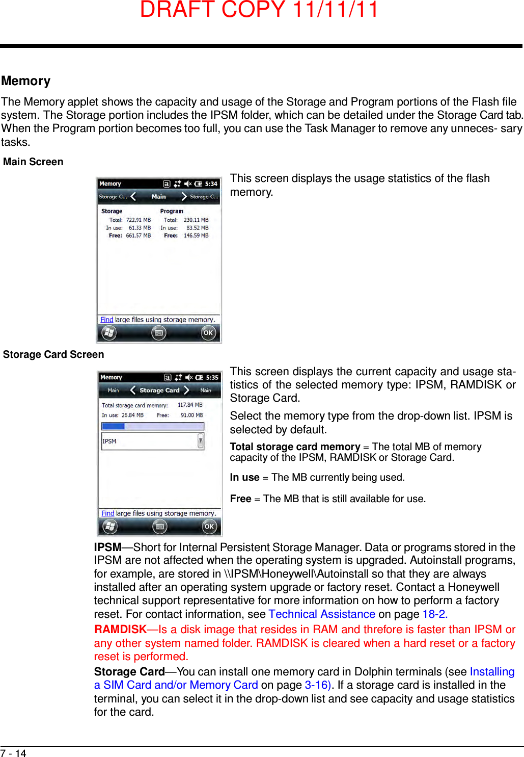
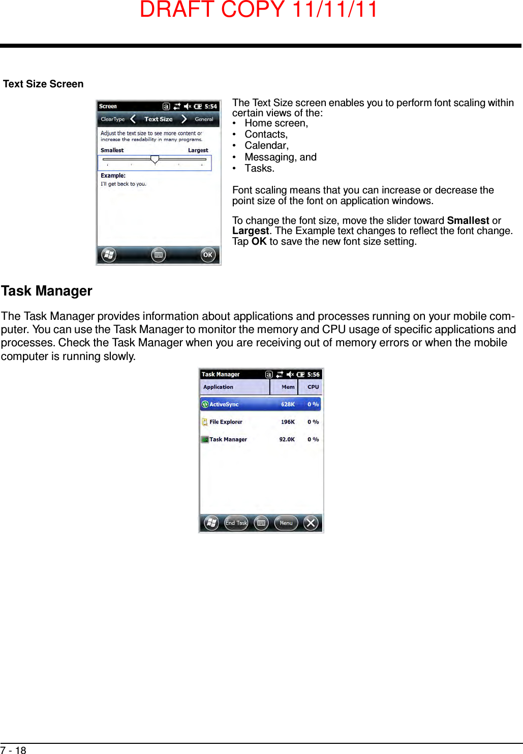
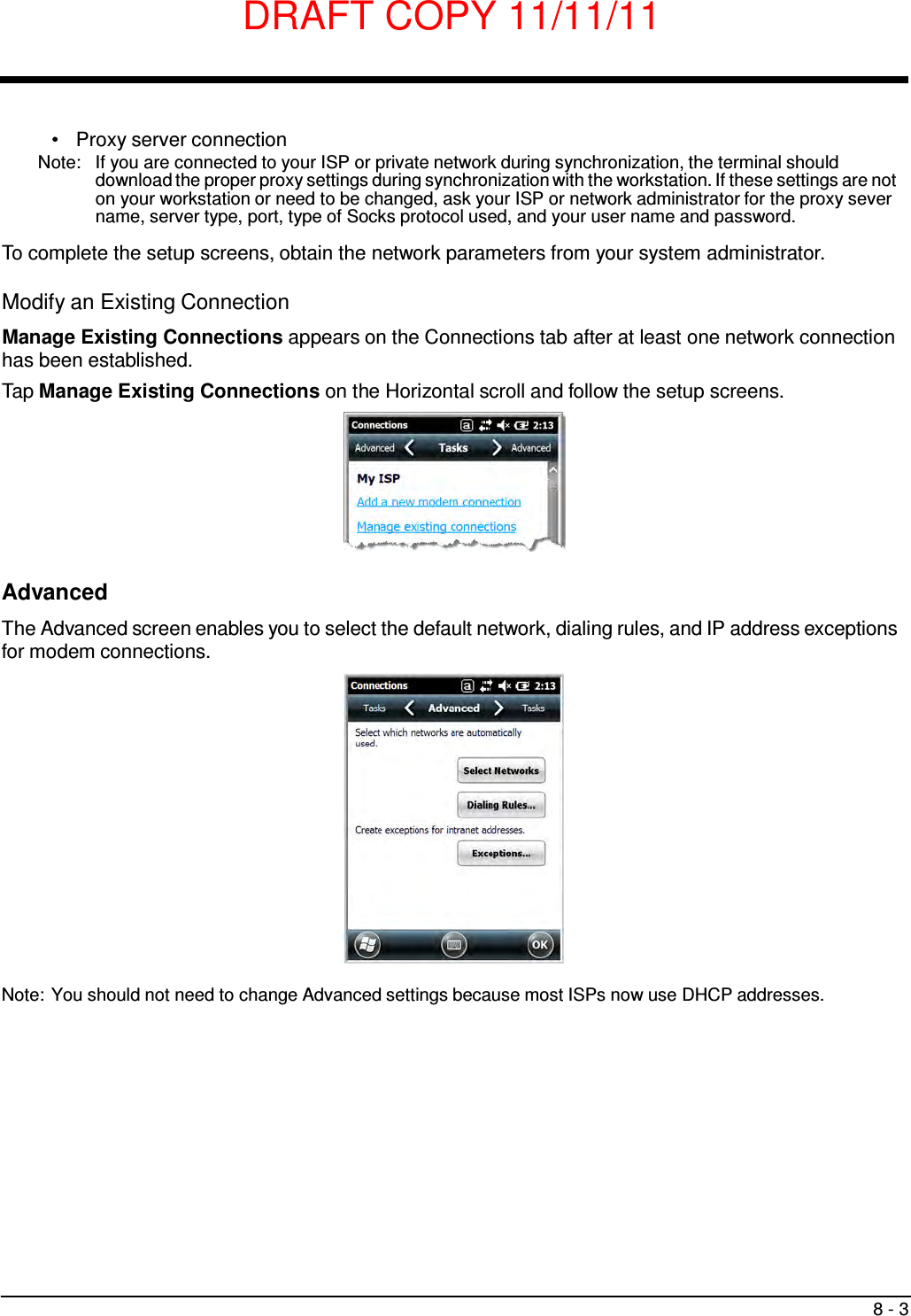
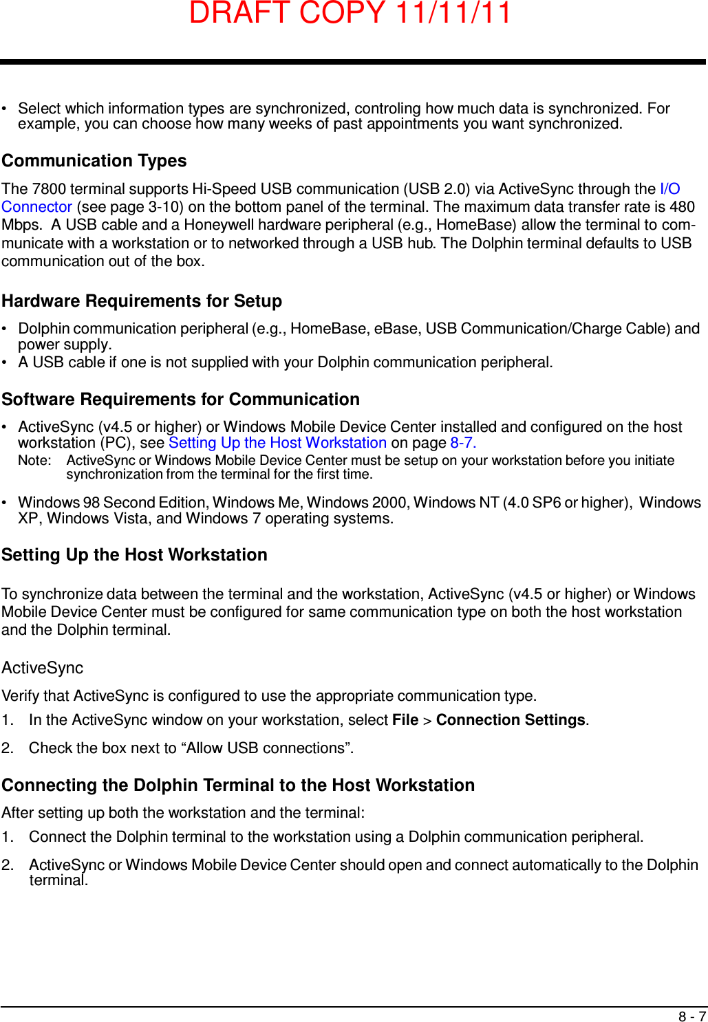
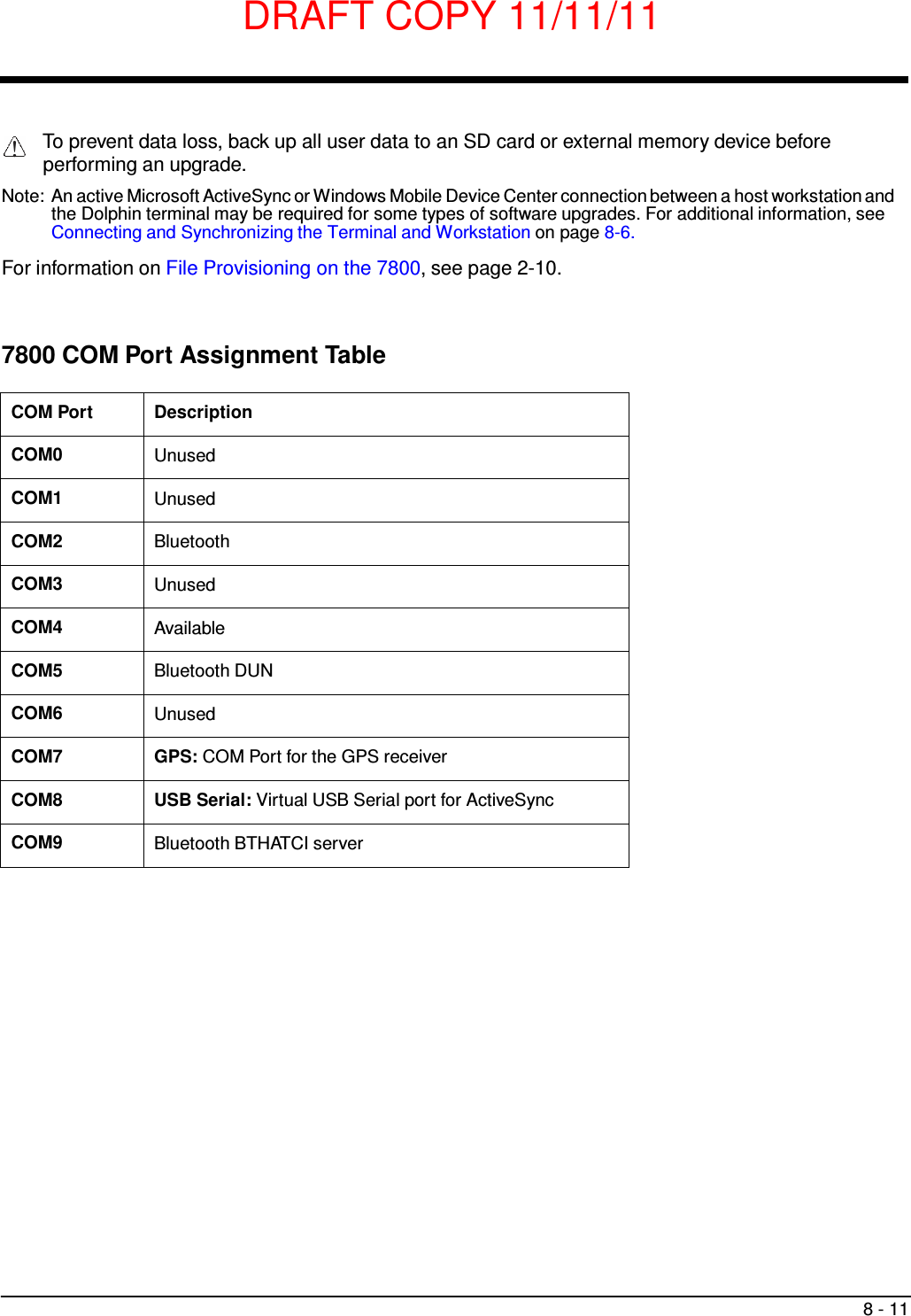
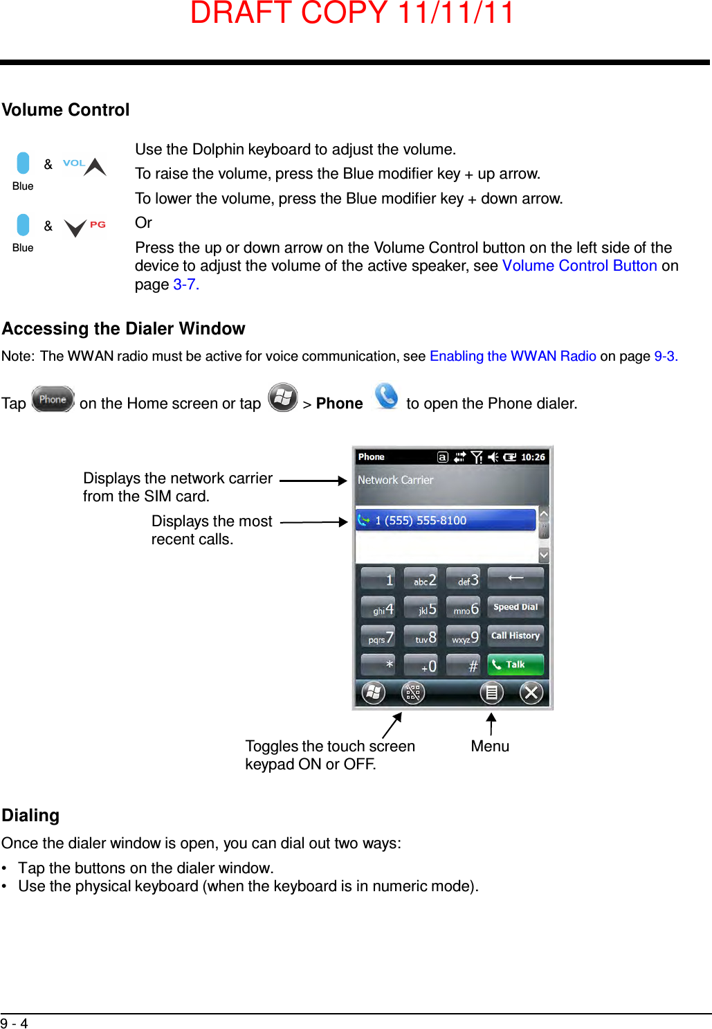
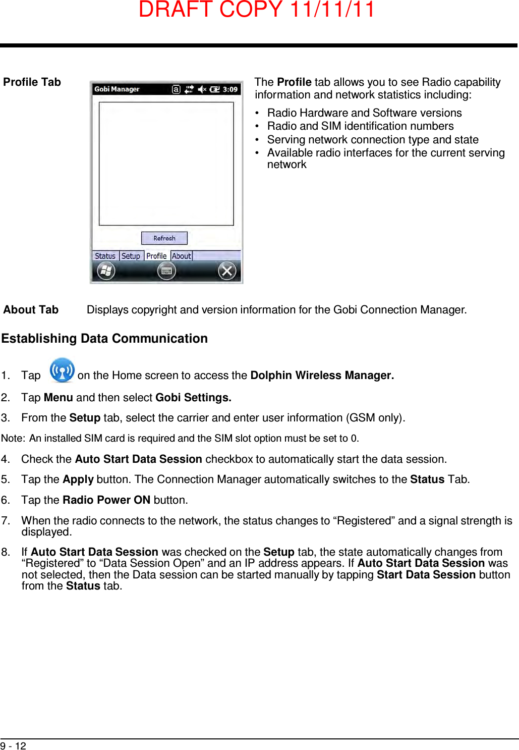
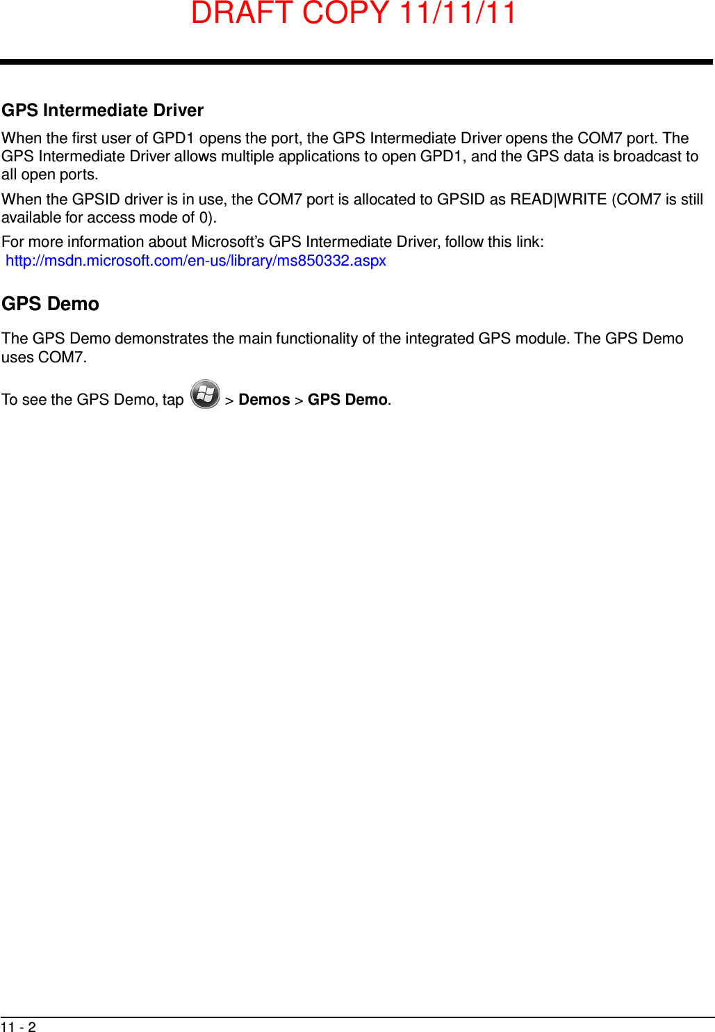
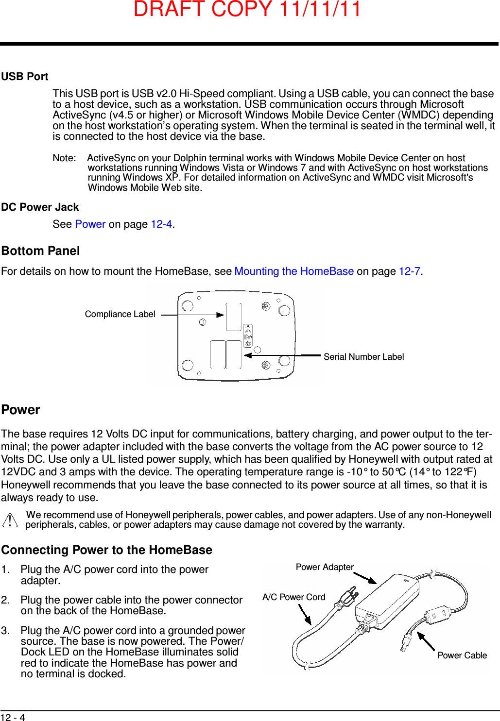
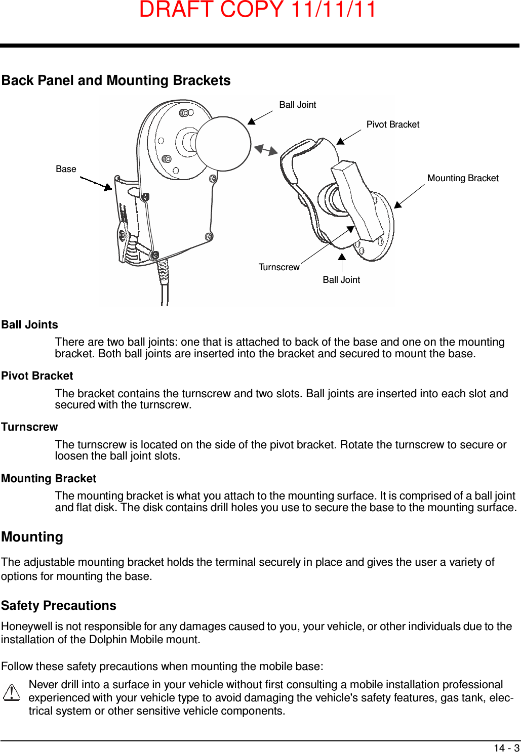
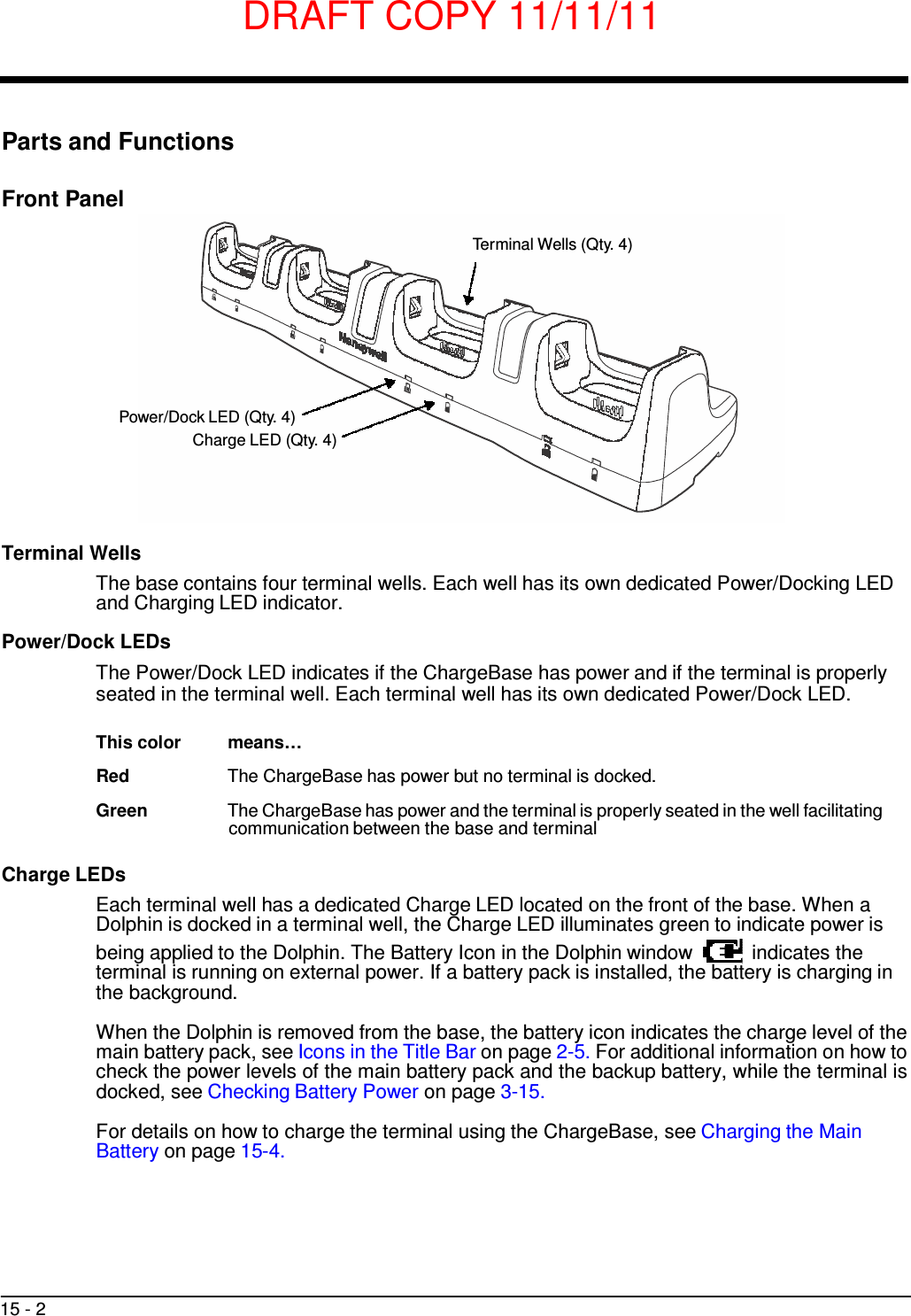
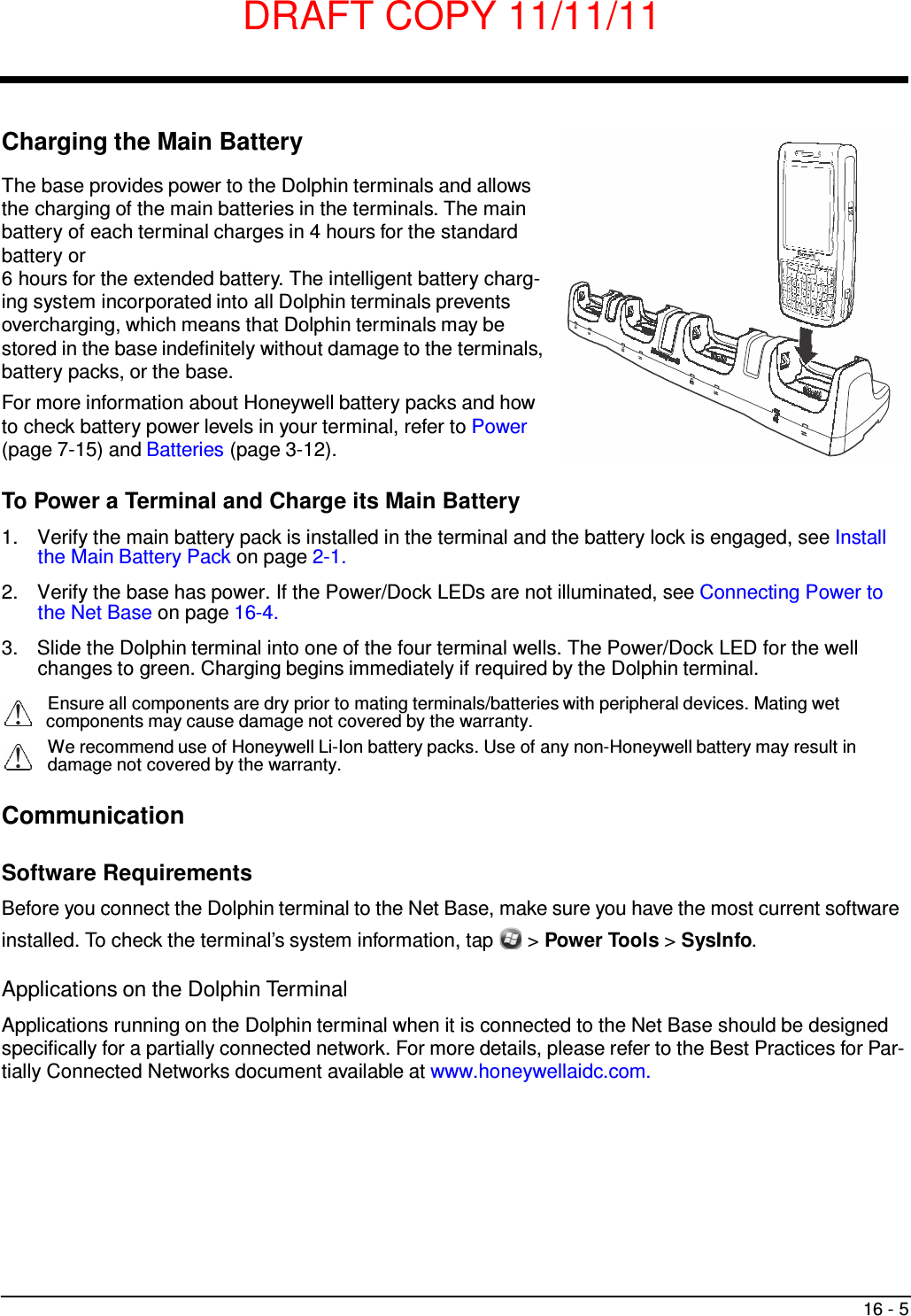
![DRAFT COPY 11/11/11 13 - 8 Optional Hardware Mount On the bottom of the HomeBase there are four mounting holes with a maximum depth of 7 mm that can be used to secure the base to a horizontal surface such as a desktop or workbench using M3 self tap- ping screws. Optional Mounting Holes for M3 self tapping screws, Qty. 4. Maximum thread depth of 7 mm. 101 mm [3.98 in.] 98 mm [3.86 in.] CL 90 mm [3.54 in.]](https://usermanual.wiki/Honeywell/7800LW.user-manual/User-Guide-1582941-Page-144.png)
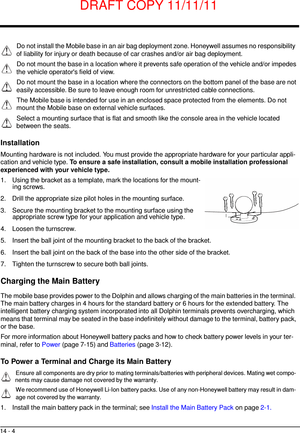

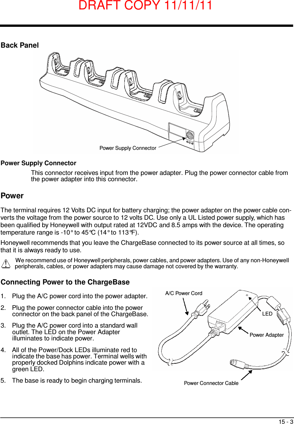

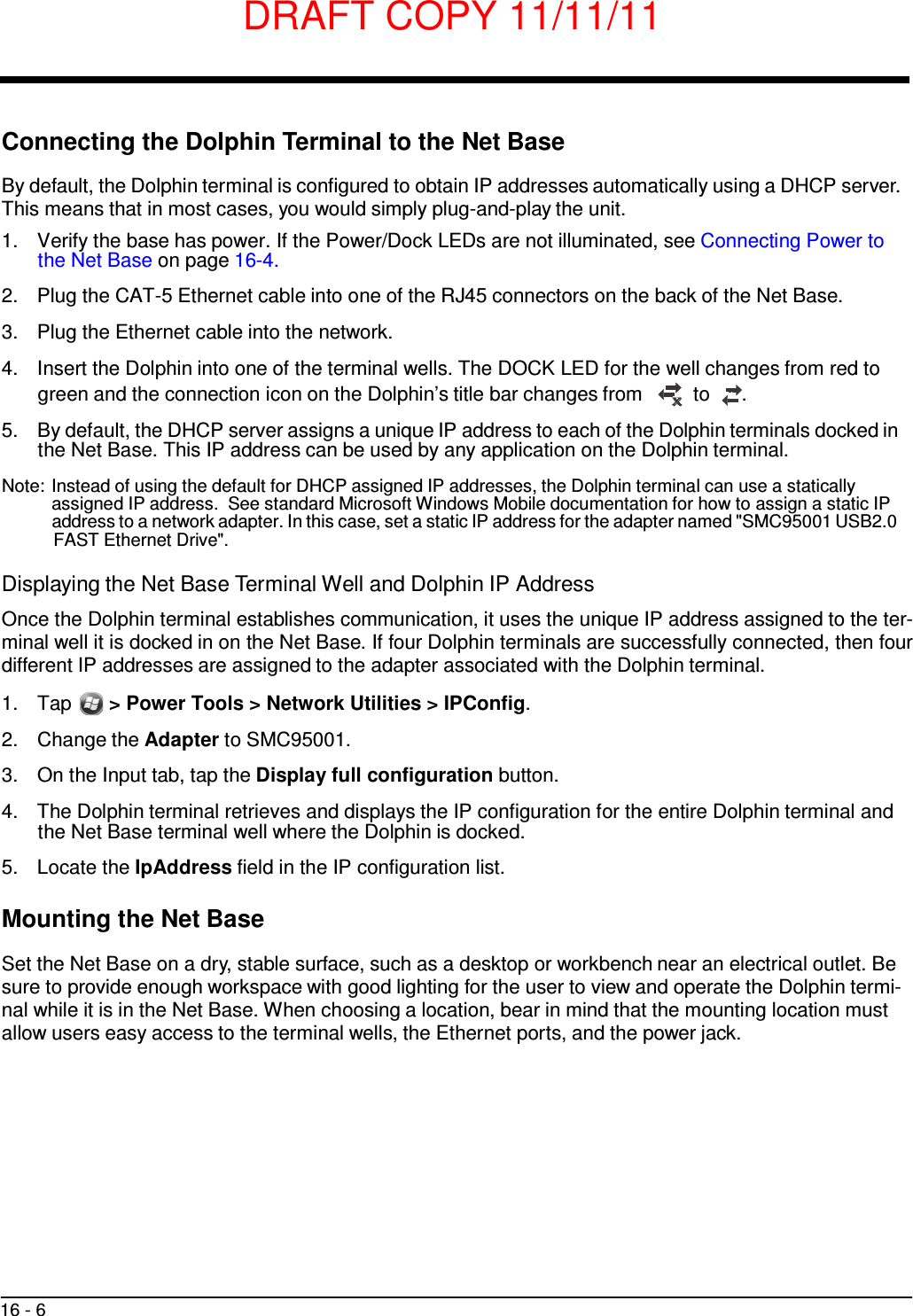
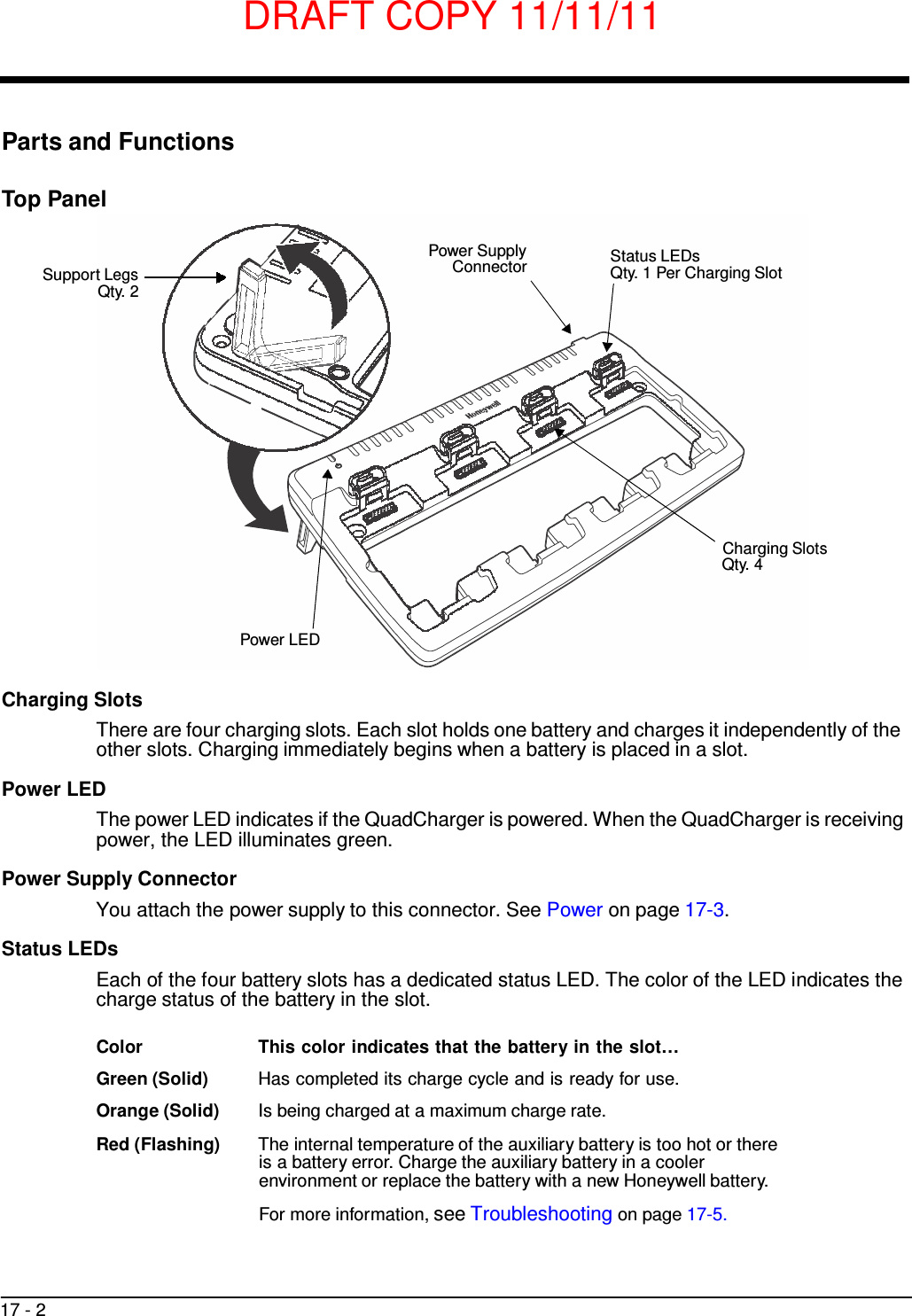
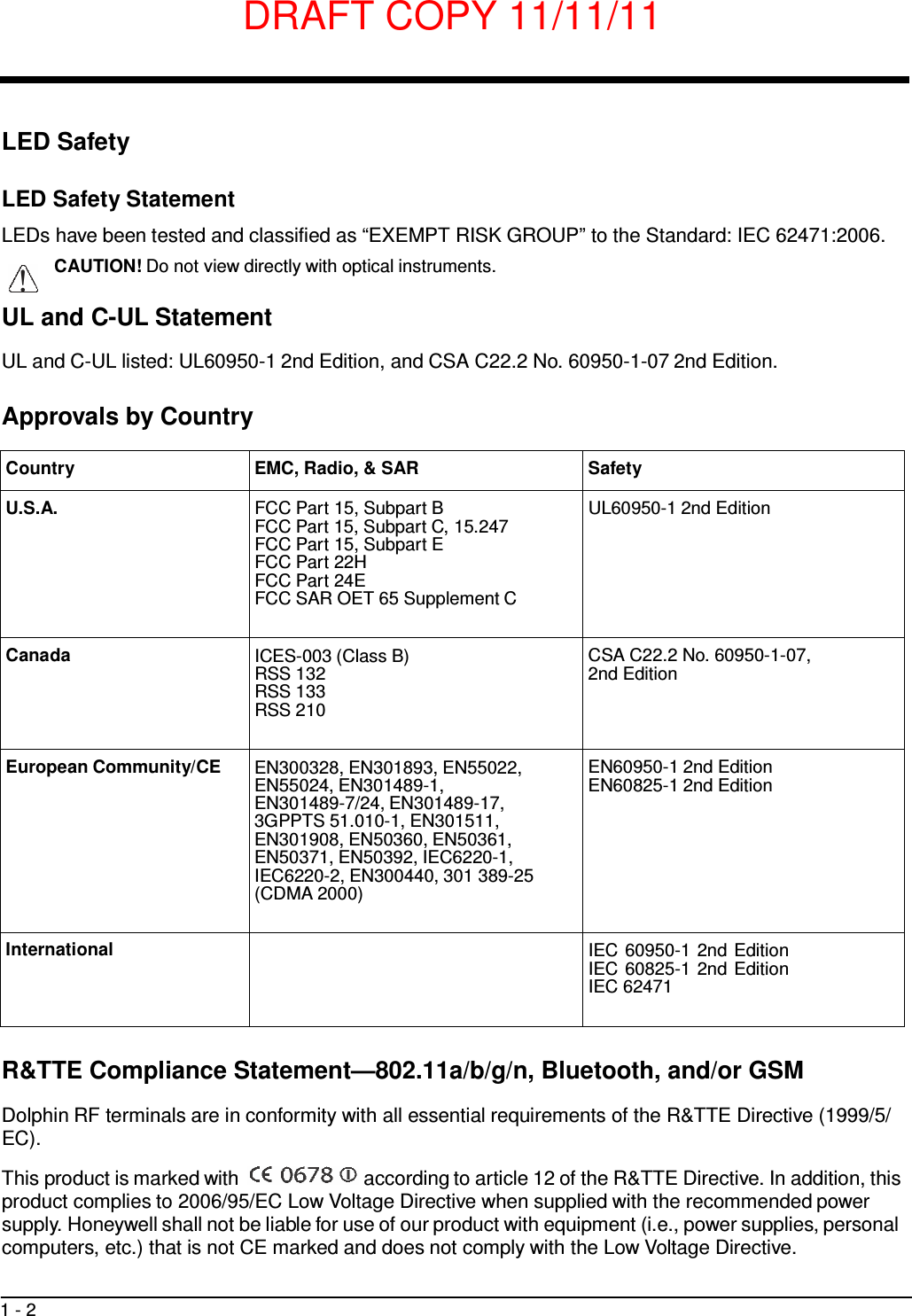
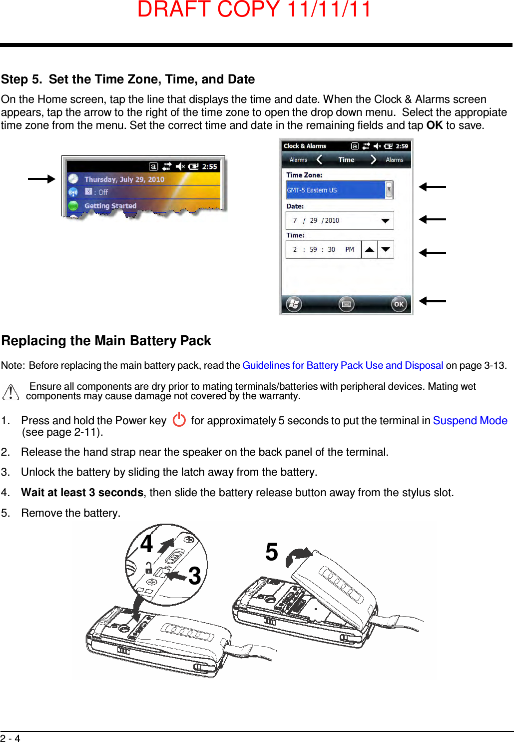
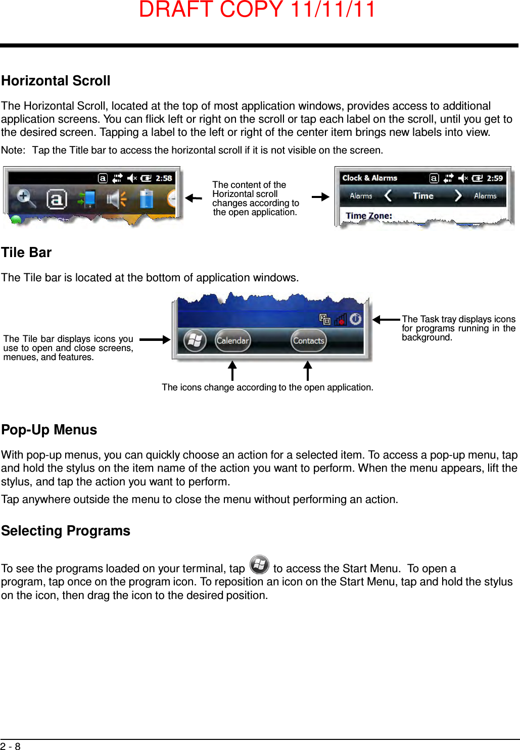
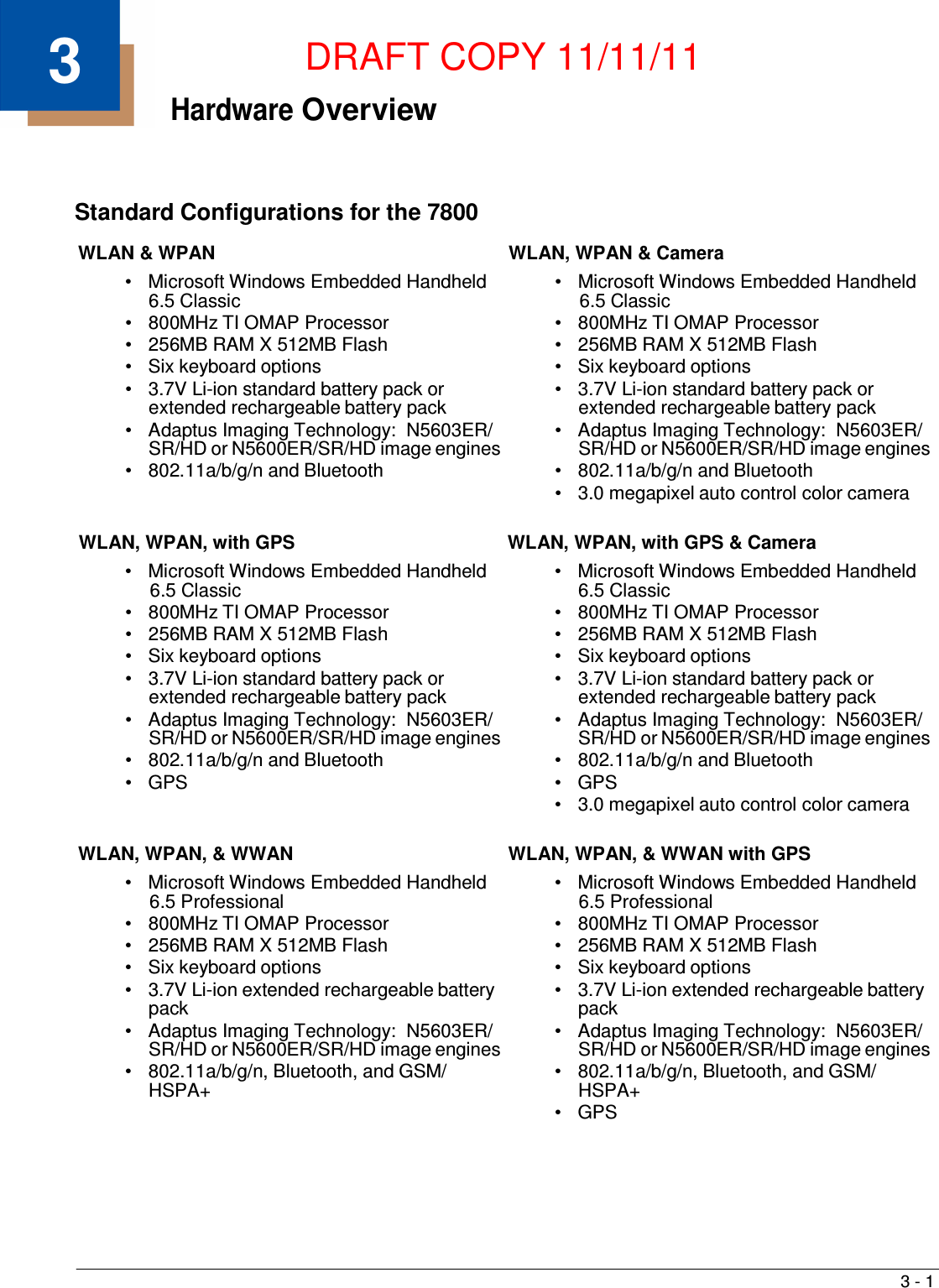
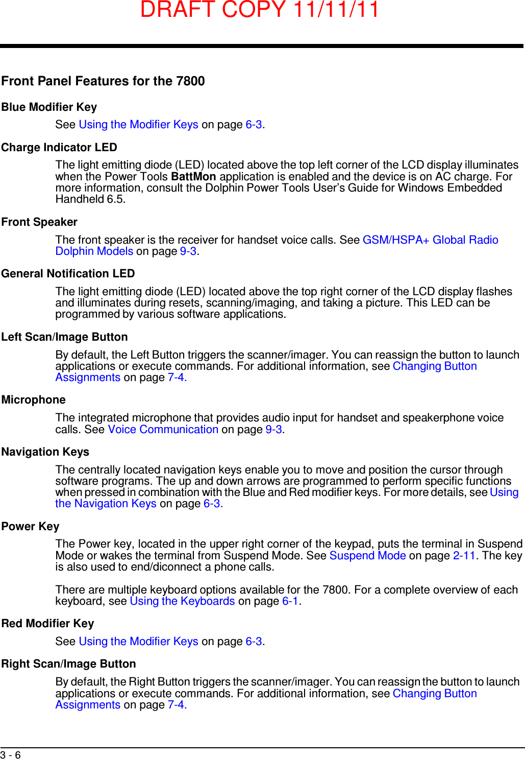
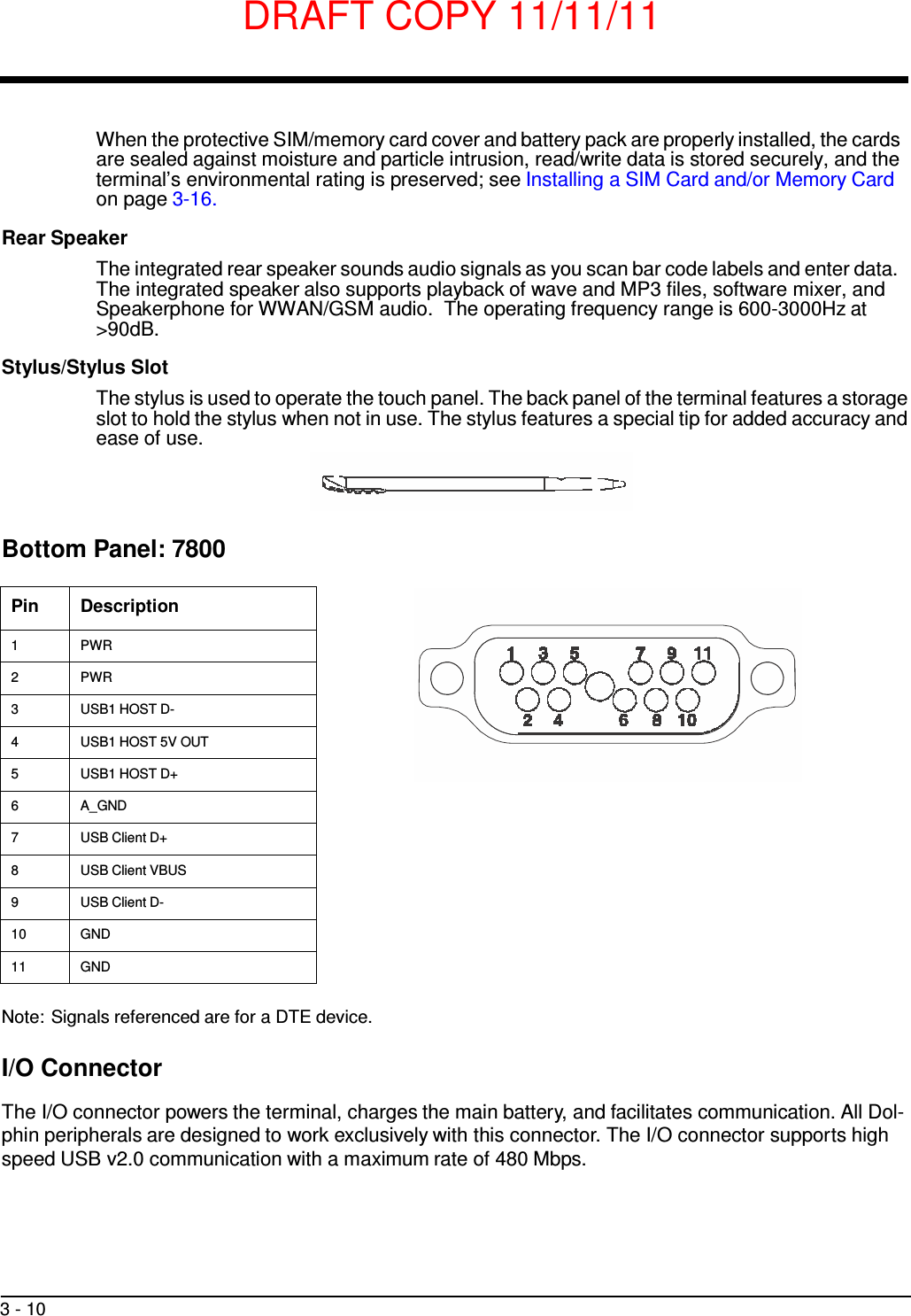
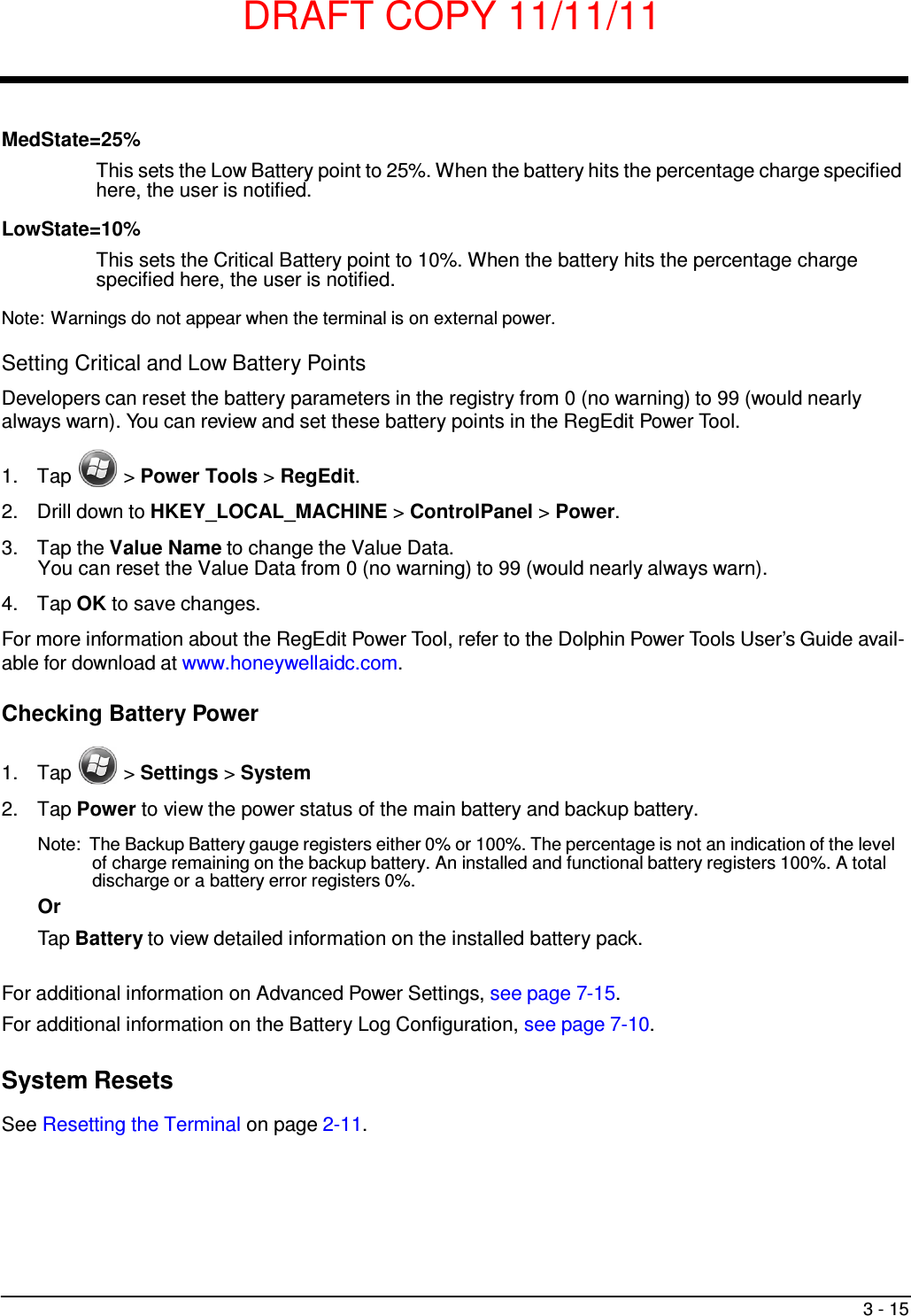
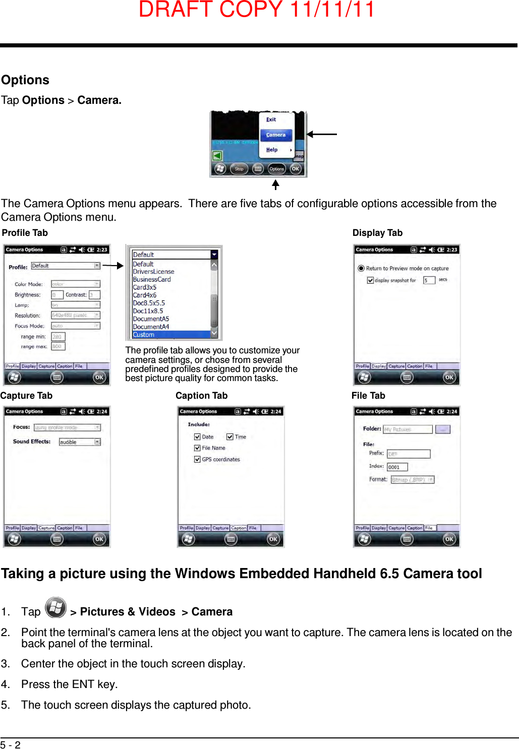
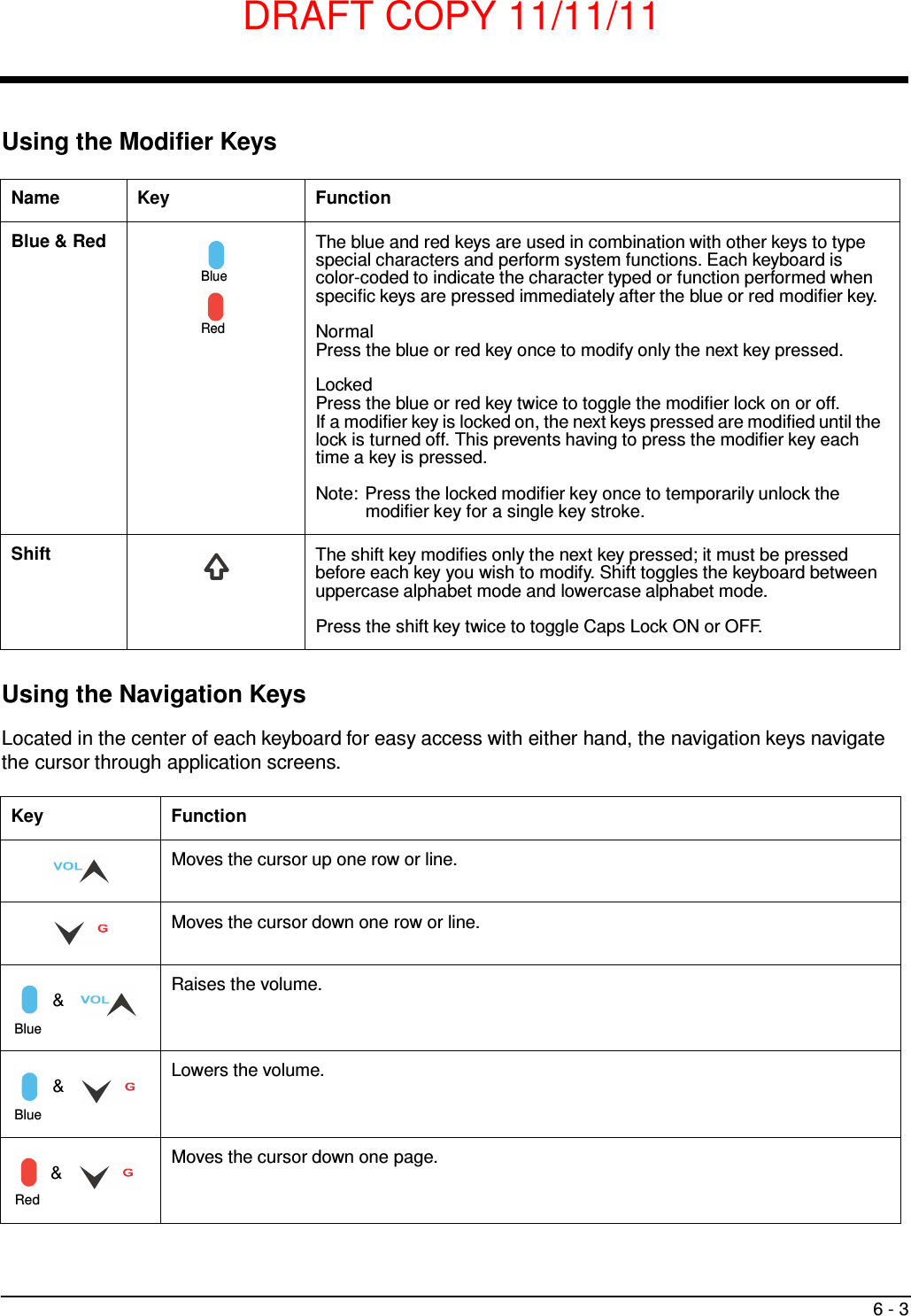
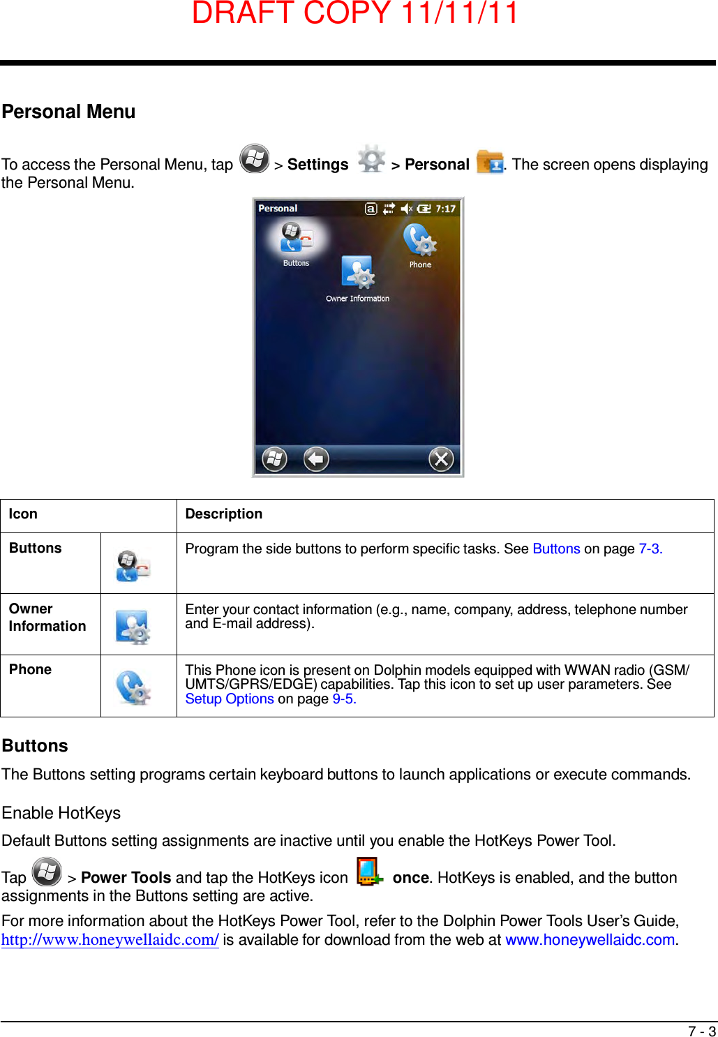
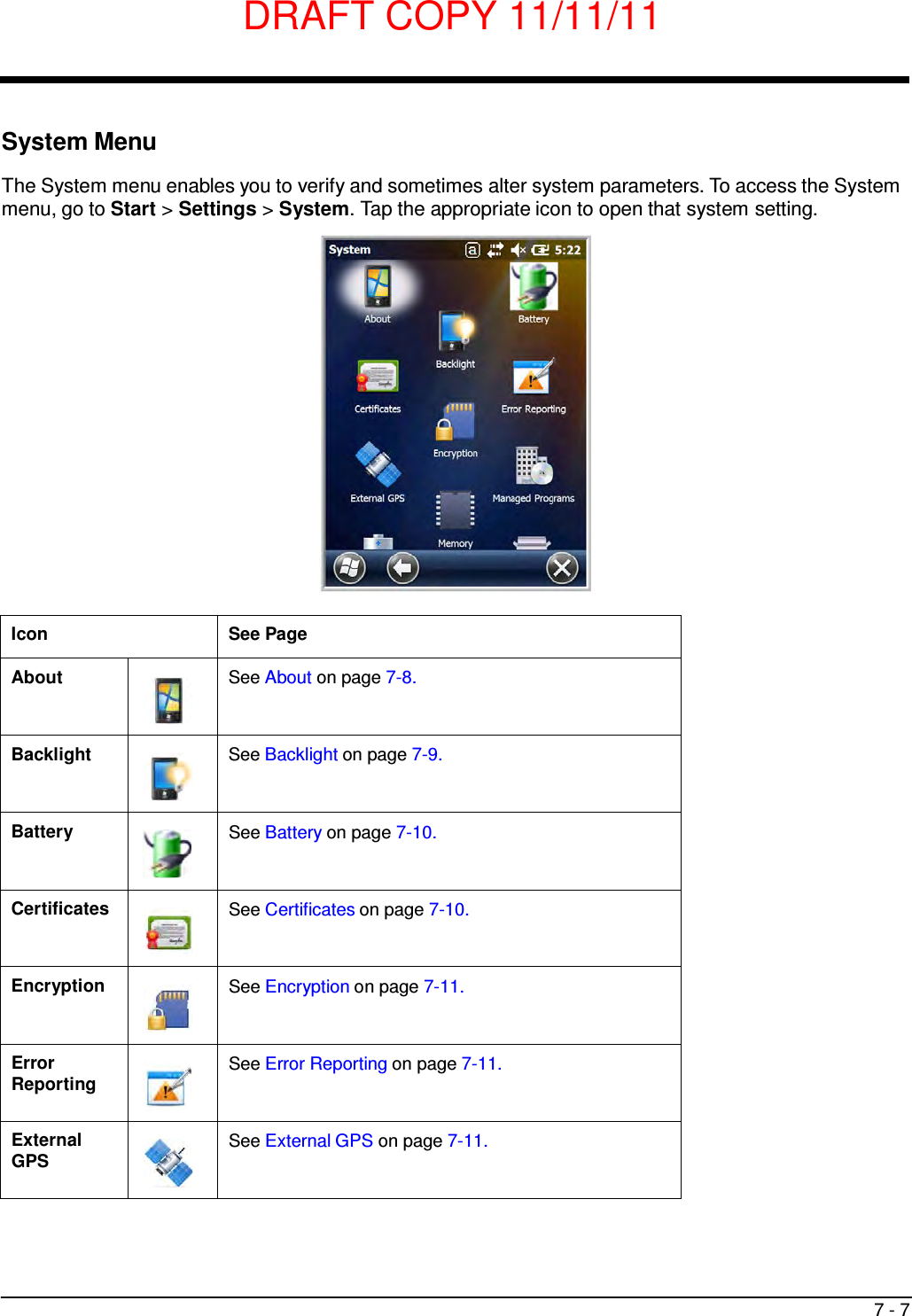
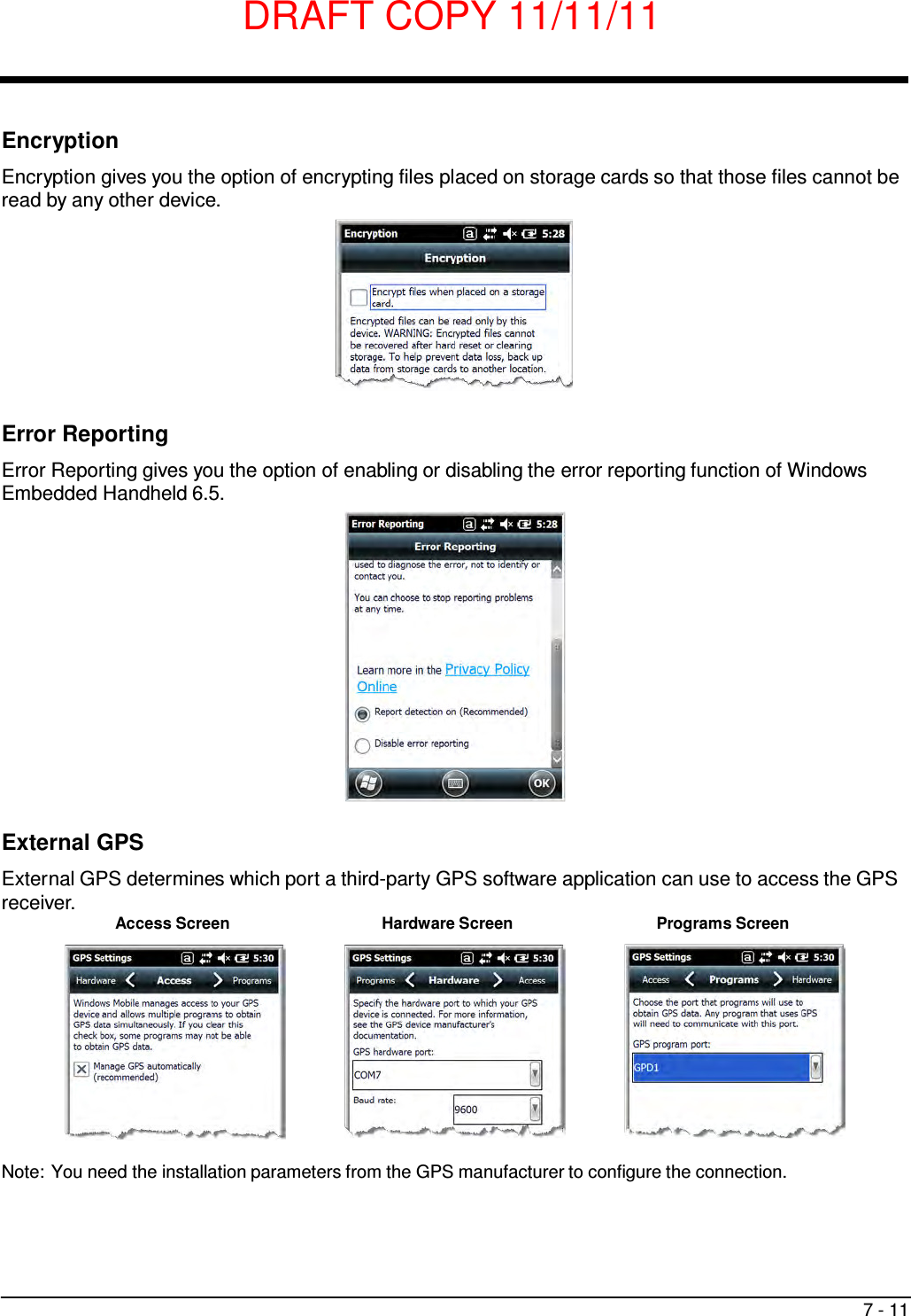
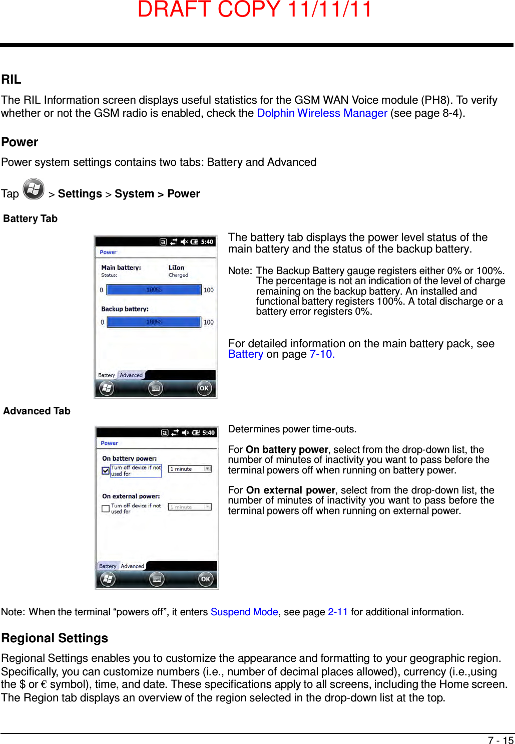
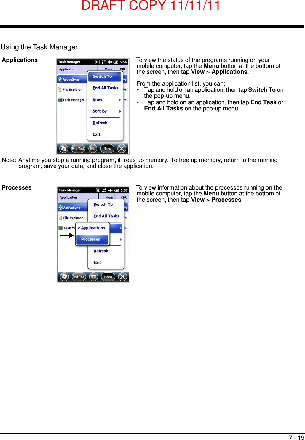
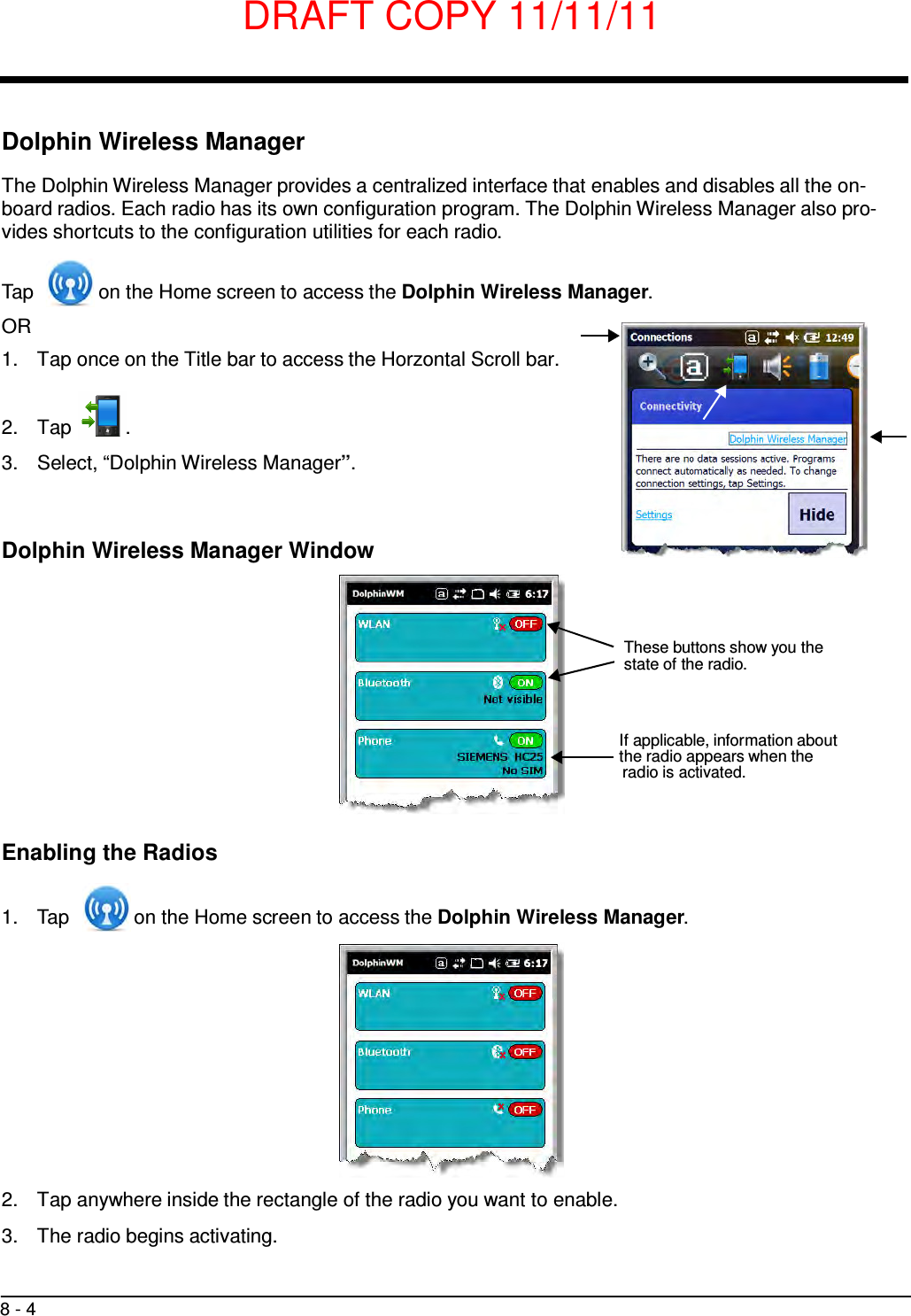
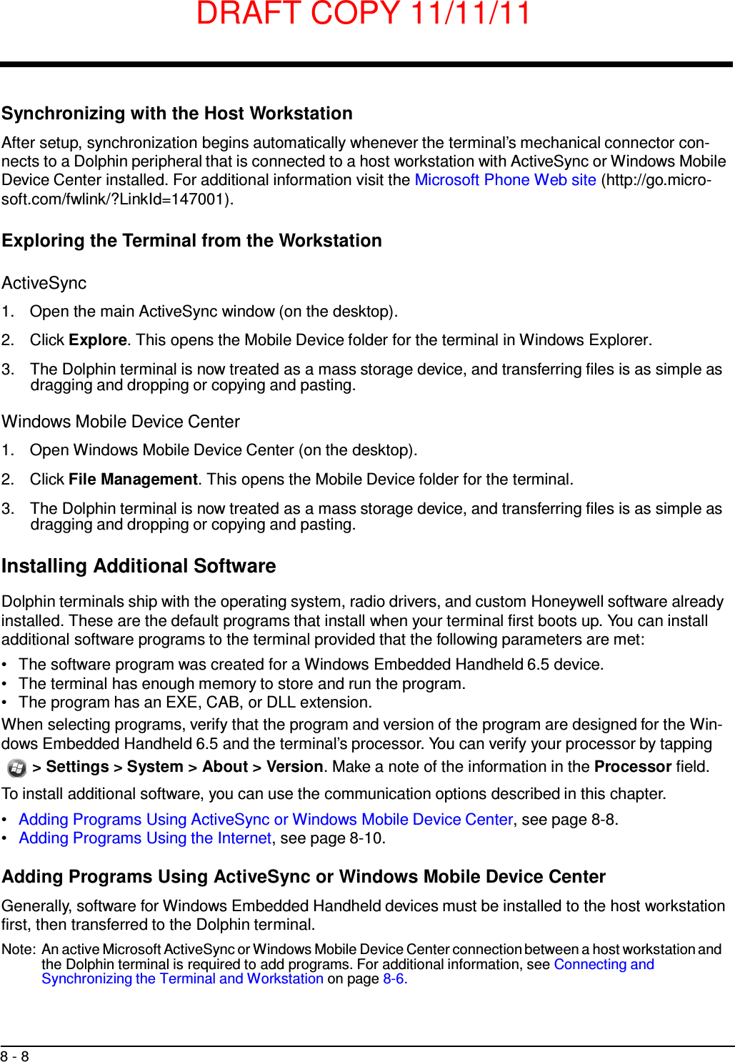
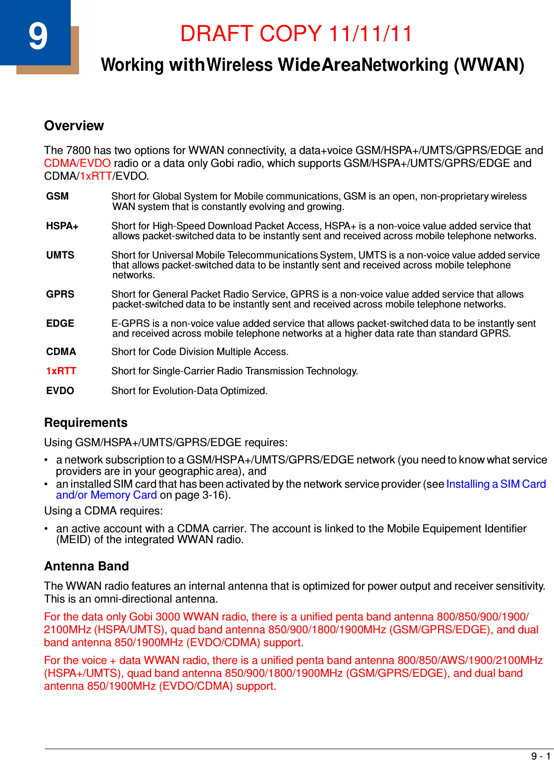
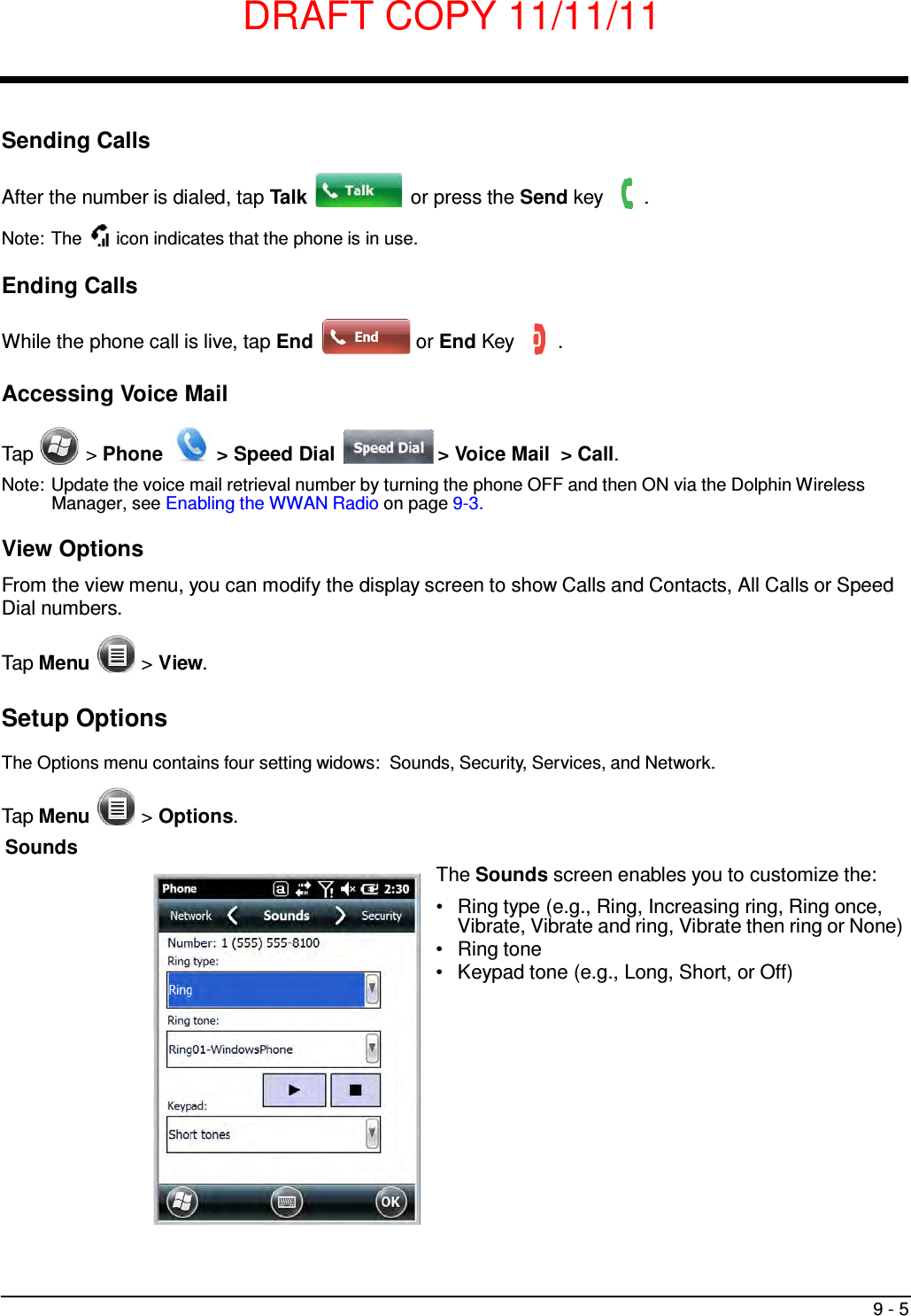
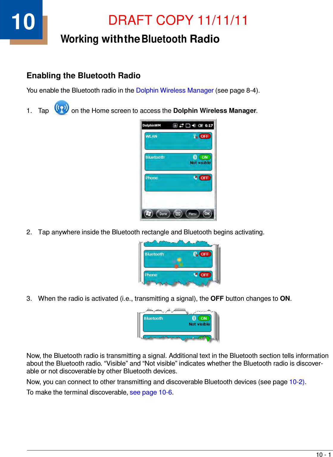
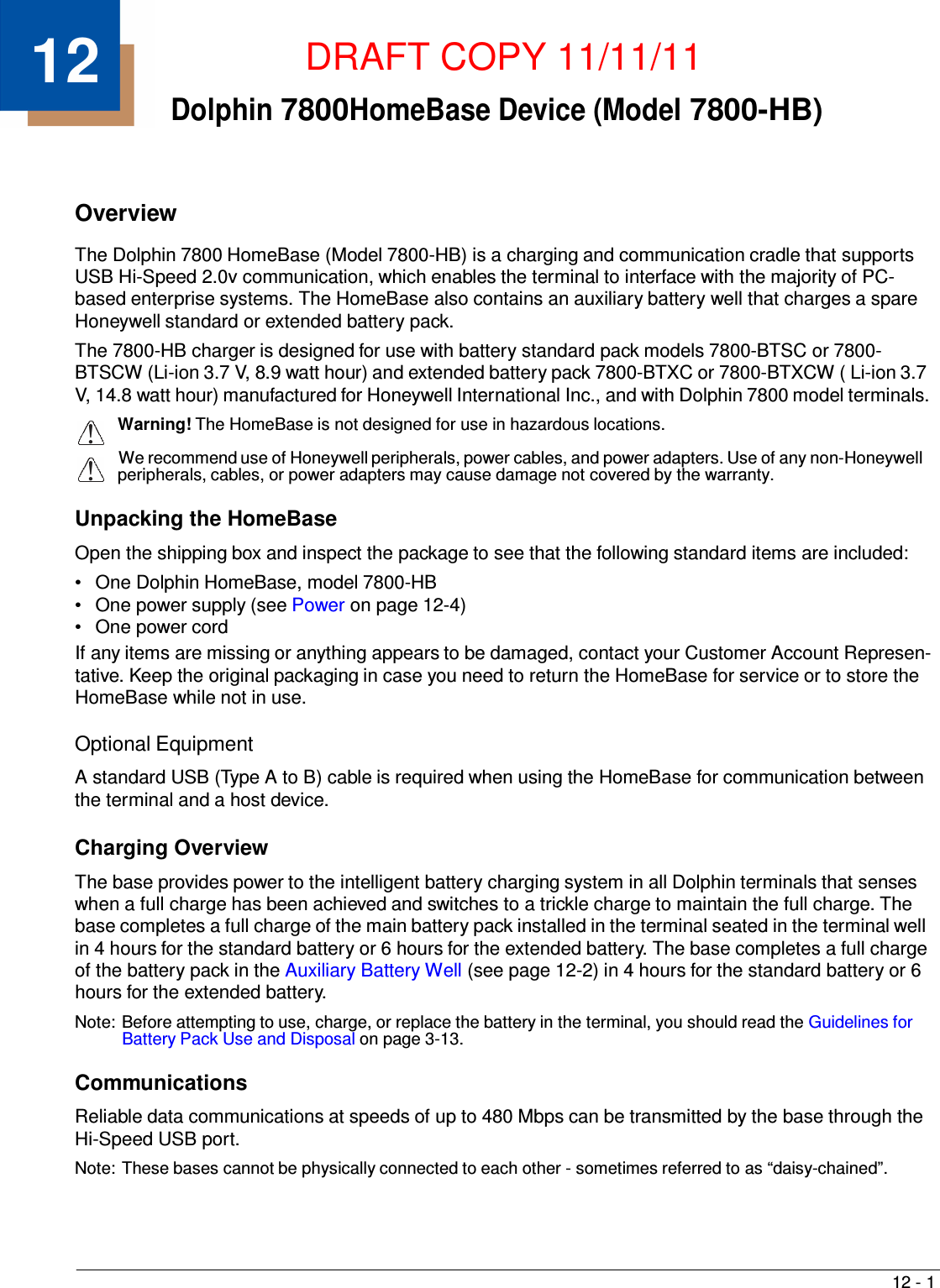
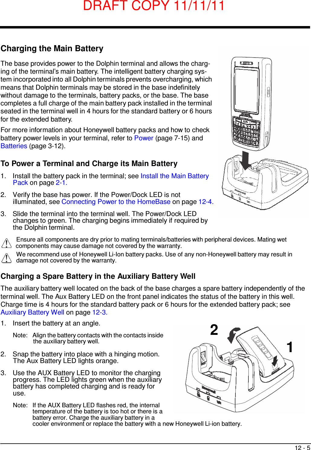
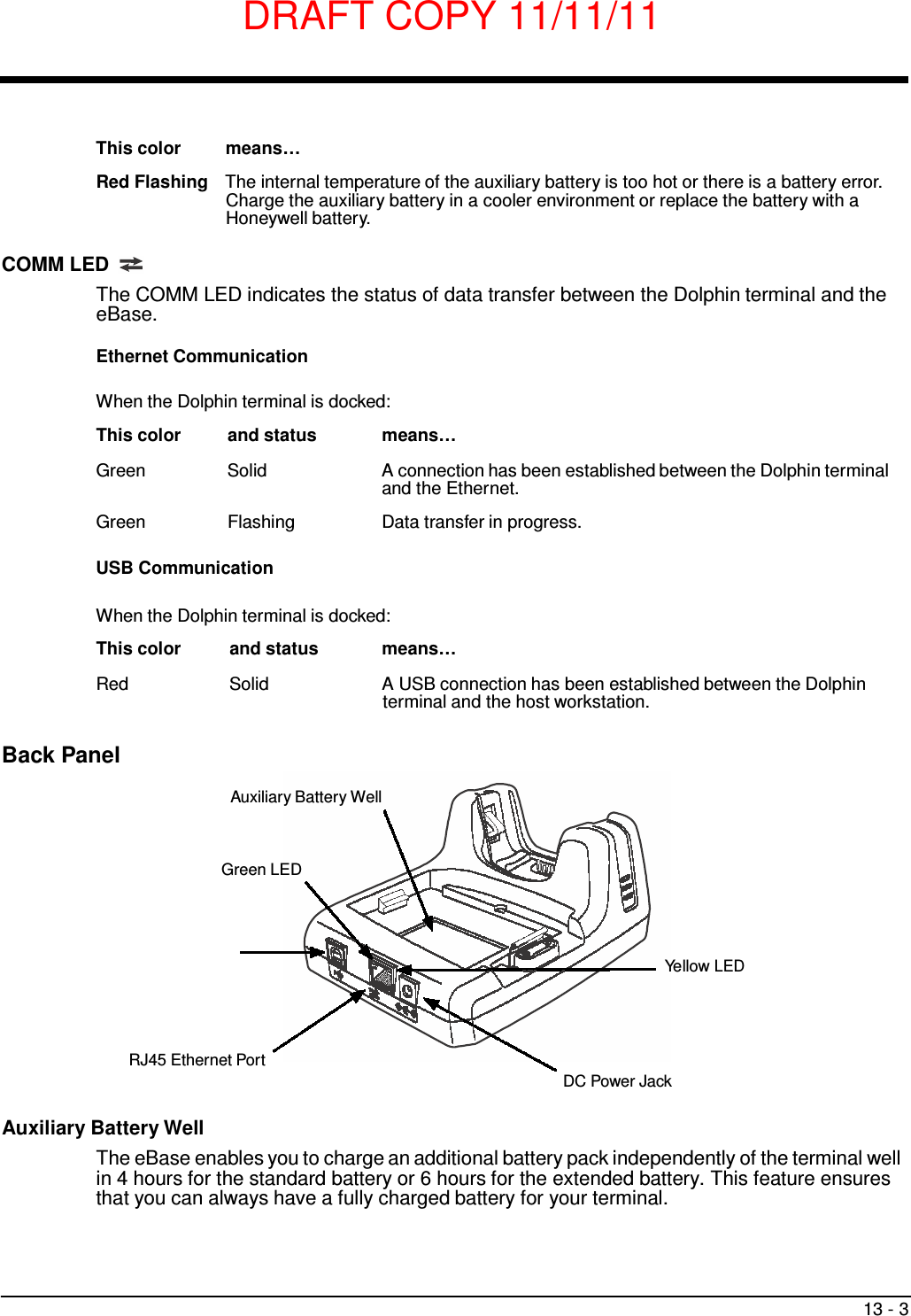
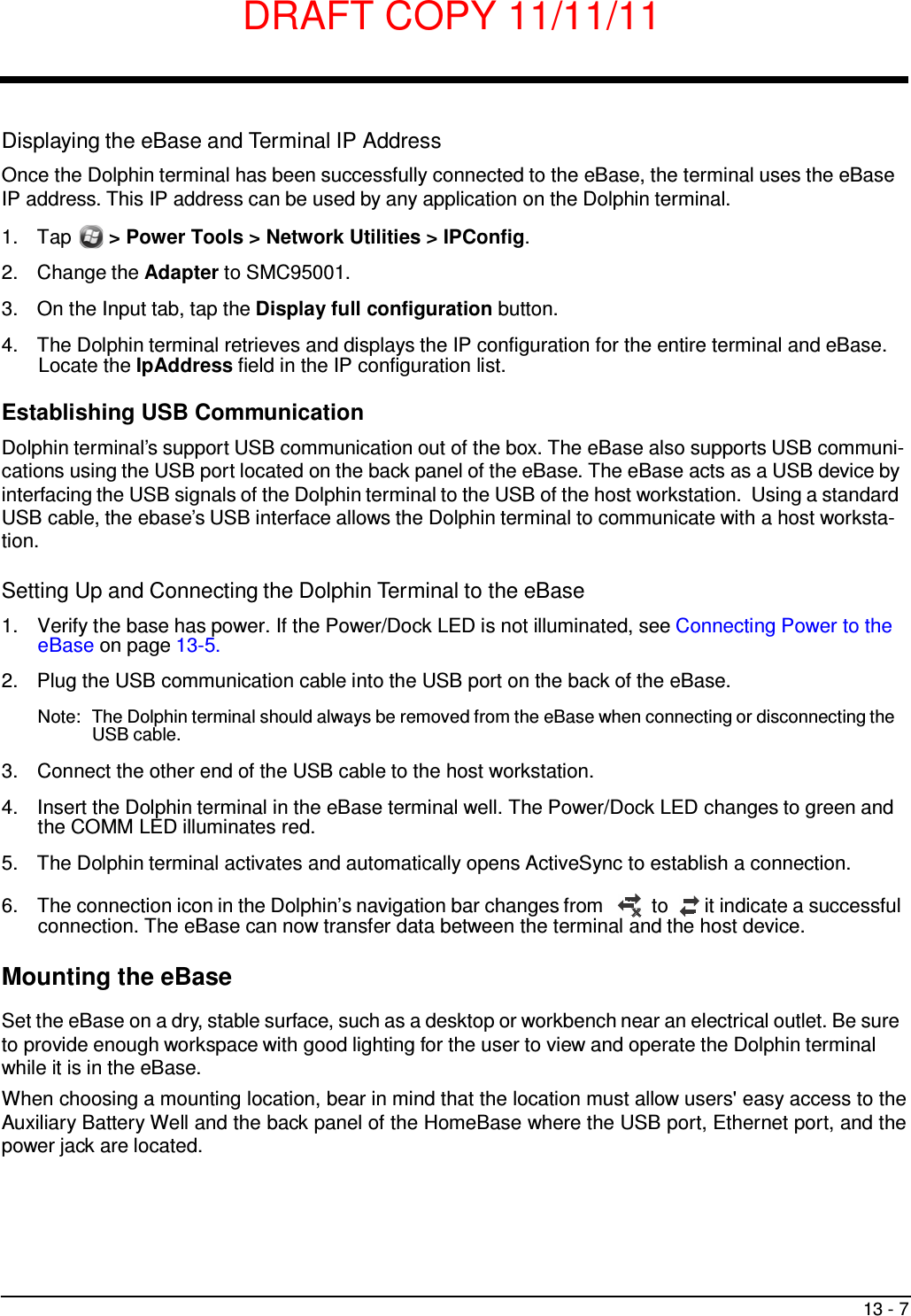
![DRAFT COPY 11/11/11 17 - 4 Mounting the QuadCharger The charger should be located on a dry, stable surface and can be mounted on a flat, horizontal surface such as a desktop or workbench. When choosing a location, always bear in mind that: • the mounting location must allow users easy access to the power connector. • the charger should be oriented so that users can easily insert and remove battery packs and see the status LEDs. Optional Hardware Mount Bottom Panel 268.6 mm [10.57 in.] 93 mm [3.66 in.] 45mm [1.77 in.] B B A A 60 mm [2.36 in.] 90 mm [3.54 in.] B B Optional Mounting Holes Option Size Qty. A 6 mm [0.24 in.] Dia. thru hole for #6 Flat Head Phillips Dry- wall-to-Wood Screws 2 B Mounting holes for M3 self tapping screws, maximum thread depth of 7 mm 4](https://usermanual.wiki/Honeywell/7800LW.user-manual/User-Guide-1582941-Page-168.png)