Honeywell 7800LW Dolphin® 7800 Mobile Computer User Manual
Honeywell International Inc Dolphin® 7800 Mobile Computer
Contents
- 1. user manual
- 2. User Manual
user manual

DRAFT COPY 11/11/11
Dolphin™ 7800
with
Windows
®
Embedded Handheld
6.5
User’s Guide

DRAFT COPY 11/11/11
Disclaimer
Honeywell International Inc. (“HII”) reserves the right to make changes in specifications and other
information contained in this document without prior notice, and the reader should in all cases consult HII
to determine whether any such changes have been made. The information in this publication does not
represent a commitment on the part of HII.
HII shall not be liable for technical or editorial errors or omissions contained herein; nor for incidental or
consequential damages resulting from the furnishing, performance, or use of this material.
This document contains proprietary information that is protected by copyright. All rights are reserved. No
part of this document may be photocopied, reproduced, or translated into another language without the
prior written consent of HII.
Web Address: www.honeywellaidc.com
Trademarks
Dolphin, Dolphin RF, HomeBase, Mobile Base, ChargeBase, Net Base and QuadCharger are trademarks
or registered trademarks of Hand Held Products, Inc. or Honeywell International Inc.
Microsoft, Windows, Windows Mobile, Windows Phone, Windows Embedded Handheld, Windows CE,
Windows 98 Second Edition, Windows NT, Windows 2000, Windows ME, Windows XP, Windows 7,
Windows Vista, ActiveSync, Outlook, and the Windows logo are trademarks or registered trademarks of
Microsoft Corporation.
The Bluetooth trademarks are owned by Bluetooth SIG, Inc., U.S.A. and licensed to Honeywell.
Other product names mentioned in this manual may be trademarks or registered trademarks of their
respective companies and are the property of their respective owners.
Patents
For patent information, please refer to www.honeywellaidc.com/patents.
©2011 Honeywell International Inc. All rights reserved.

DRAFT COPY 11/11/11
iii
Table
of Contents
Chapter 1 - Dolphin 7800 Terminal Agency Information
Laser Safety .........................................................................................................................1-1
Label Locations ..............................................................................................................1-1
Model Number, Serial Number and IMEI Labels............................................................1-1
Laser Safety Label .........................................................................................................1-1
Laser Safety Statement..................................................................................................1-1
LED Safety ...........................................................................................................................1-2
LED Safety Statement....................................................................................................1-2
UL and C-UL Statement.......................................................................................................1-2
Approvals by Country...........................................................................................................1-2
R&TTE Compliance Statement—802.11a/b/g/n, Bluetooth, and/or GSM............................1-3
Dolphin RF Terminal—802.11a/b/g/n, Bluetooth, and/or GSM ............................................1-3
Canadian Compliance..........................................................................................................1-4
Conformité à la règlementation canadienne ........................................................................1-4
RF Exposure Information (SAR) ..........................................................................................1-4
For European Community Users .........................................................................................1-5
Waste Electrical and Electronic Equipment Information ......................................................1-5
China RoHS .........................................................................................................................1-6
Pacemakers, Hearing Aids and Other Electrically Powered Devices ..................................1-6
Hearing Aid Compatibility (HAC)..........................................................................................1-6
Microwaves ..........................................................................................................................1-7
Chapter 2 - Getting Started
Out of the Box ......................................................................................................................2-1
Initial Setup for Dolphin 7800 Terminals ..............................................................................2-1
Replacing the Main Battery Pack .........................................................................................2-4
Home Screen .......................................................................................................................2-5
Title Bar................................................................................................................................2-5
Icons in the Title Bar ............................................................................................................2-5
Horizontal Scroll ...................................................................................................................2-8
Tile Bar.................................................................................................................................2-8
Pop-Up Menus .....................................................................................................................2-8
Selecting Programs..............................................................................................................2-8
File Explorer .........................................................................................................................2-9
File Provisioning on the 7800.............................................................................................2-10
Search................................................................................................................................2-10
Resetting the Terminal .......................................................................................................2-11
Soft Reset (Warm Boot) ...............................................................................................2-11
Hard Reset (Cold Boot) ................................................................................................2-11
Factory Reset ...............................................................................................................2-11
Suspend Mode ...................................................................................................................2-11
Chapter 3 - Hardware Overview
Standard Configurations for the 7800 ..................................................................................3-1
Peripherals for the 7800.......................................................................................................3-3

DRAFT COPY 11/11/11
iv
Accessories for the 7800 ..................................................................................................... 3-4
Front Panel: 7800 ................................................................................................................ 3-5
Front Panel Features for the 7800................................................................................. 3-6
Back Panel: 7800 ............................................................................................................... 3-8
Back Panel Features for the 7800 ................................................................................. 3-9
Bottom Panel: 7800 ........................................................................................................... 3-10
I/O Connector .................................................................................................................... 3-10
Using the Touch Panel ...................................................................................................... 3-11
Installing a Screen Protector........................................................................................ 3-11
Healthcare Housing ........................................................................................................... 3-11
Batteries ............................................................................................................................ 3-12
Main Battery Pack........................................................................................................ 3-12
Internal Backup Battery ............................................................................................... 3-14
Managing Battery Power ............................................................................................. 3-14
Checking Battery Power .............................................................................................. 3-15
System Resets .................................................................................................................. 3-15
Installing a SIM Card and/or Memory Card ....................................................................... 3-16
Installation.................................................................................................................... 3-16
Chapter 4 - Using the Scan Image Engine
Overview.............................................................................................................................. 4-1
Laser Safety ........................................................................................................................ 4-1
N5603 Beam Divergence Angle .................................................................................... 4-1
LED Safety .......................................................................................................................... 4-1
Image Engine Specifications ............................................................................................... 4-1
Depth of Field ................................................................................................................ 4-1
Supported Bar Code Symbologies ..................................................................................... 4-3
Decoding ............................................................................................................................. 4-4
To Decode a Bar Code .................................................................................................. 4-4
Aiming Beam Options .................................................................................................... 4-5
Capturing Images ................................................................................................................ 4-6
Taking an Image ............................................................................................................ 4-6
Uploading Images.......................................................................................................... 4-7
Chapter 5 - Using the Color Camera
Overview.............................................................................................................................. 5-1
Taking a picture using the Camera Demo tool .................................................................... 5-1
Taking a picture using the Windows Embedded Handheld 6.5 Camera tool ...................... 5-2
Recording Video .................................................................................................................. 5-3
Uploading Pictures and Videos...................................................................................... 5-4
Chapter 6 - Using the Keyboards
Available Keyboards ............................................................................................................ 6-1
Keyboard Combinations ................................................................................................ 6-2
Common Buttons ........................................................................................................... 6-2
Using the Function Keys...................................................................................................... 6-2
Using the Modifier Keys ...................................................................................................... 6-3

DRAFT COPY 11/11/11
v
Using the Navigation Keys .................................................................................................. 6-3
30-Key Numeric Keyboard .................................................................................................. 6-4
30-Key Numeric Keyboard Combinations...................................................................... 6-4
30-Key Numeric (Calculator) Keyboard ............................................................................... 6-6
30-Key Numeric (Calculator) Keyboard Combinations .................................................. 6-6
46-Key QWERTY Keyboard ................................................................................................ 6-8
46-Key QWERTY Keyboard Combinations ................................................................... 6-8
46-Key AZERTY Keyboard................................................................................................ 6-11
46-Key AZERTY Keyboard Combinations................................................................... 6-11
46-Key QWERTZ Keyboard .............................................................................................. 6-14
46-Key QWERTZ Keyboard Combinations ................................................................. 6-14
Chapter 7 - System Settings
Overview.............................................................................................................................. 7-1
Clock & Alarms .................................................................................................................... 7-2
Personal Menu .................................................................................................................... 7-3
Buttons........................................................................................................................... 7-3
System Menu....................................................................................................................... 7-7
About ............................................................................................................................. 7-8
Backlight ........................................................................................................................ 7-9
Battery ......................................................................................................................... 7-10
Certificates................................................................................................................... 7-10
Encryption.................................................................................................................... 7-11
Error Reporting ............................................................................................................ 7-11
External GPS ............................................................................................................... 7-11
Five Volt Control .......................................................................................................... 7-12
Smart Sensor............................................................................................................... 7-12
Managed Programs ..................................................................................................... 7-13
Memory........................................................................................................................ 7-14
RIL ............................................................................................................................... 7-15
Power........................................................................................................................... 7-15
Regional Settings......................................................................................................... 7-15
Remove Programs....................................................................................................... 7-16
Screen ............................................................................................................................... 7-17
Task Manager.................................................................................................................... 7-18
Chapter 8 - Communication
Connections Menu............................................................................................................... 8-1
Connections Manager ......................................................................................................... 8-2
To Access the Connections Manager............................................................................ 8-2
Tasks ............................................................................................................................. 8-2
Advanced....................................................................................................................... 8-3
Dolphin Wireless Manager .................................................................................................. 8-4
Dolphin Wireless Manager Window............................................................................... 8-4
Enabling the Radios....................................................................................................... 8-4
Accessing Radio Configuration Utilities ......................................................................... 8-5
Network Cards ..................................................................................................................... 8-6
Connecting and Synchronizing the Terminal and Workstation ............................................ 8-6

DRAFT COPY 11/11/11
vi
Installing Additional Software .............................................................................................. 8-8
Adding Programs Using ActiveSync or Windows Mobile Device Center ....................... 8-8
Connecting the Terminal to a Wireless Network.......................................................... 8-10
Adding Programs Using the Internet............................................................................ 8-10
Software Upgrades ............................................................................................................ 8-10
7800 COM Port Assignment Table .................................................................................... 8-11
Chapter 9 - Working with Wireless Wide Area Networking (WWAN)
Overview.............................................................................................................................. 9-1
Antenna Band ................................................................................................................ 9-1
Enabling the WWAN Radio ................................................................................................. 9-3
GSM/HSPA+ Global Radio Dolphin Models ........................................................................ 9-3
Voice Communication.................................................................................................... 9-3
Audio Modes.................................................................................................................. 9-3
Volume Control .............................................................................................................. 9-4
Accessing the Dialer Window ........................................................................................ 9-4
Dialing............................................................................................................................ 9-4
Sending Calls................................................................................................................. 9-5
Ending Calls................................................................................................................... 9-5
Accessing Voice Mail..................................................................................................... 9-5
View Options.................................................................................................................. 9-5
Setup Options ...................................................................................................................... 9-5
Data Communication (GSM/HSPA+ Global Radio Dolphin Models) ................................... 9-7
System Requirements ................................................................................................... 9-7
Information Requirements ............................................................................................. 9-7
Establishing Data Communication................................................................................. 9-7
Manual Network Selection ........................................................................................... 9-10
Data Communication GSM/CDMA Dolphin Models .......................................................... 9-11
Gobi Manager .............................................................................................................. 9-11
Establishing Data Communication............................................................................... 9-12
Chapter 10 - Working with the Bluetooth Radio
Enabling the Bluetooth Radio ............................................................................................ 10-1
Pairing and Trusted Devices ............................................................................................. 10-2
Connecting to Other Bluetooth Devices ............................................................................ 10-2
Transferring Files............................................................................................................... 10-5
Making the Terminal Discoverable .................................................................................... 10-6
Enabling the Terminal to Receive Incoming Beams .................................................... 10-6
Selecting COM Ports ......................................................................................................... 10-7
Chapter 11 - Working with GPS
Overview............................................................................................................................ 11-1
Assisted GPS Support ....................................................................................................... 11-1
Powering the GPS Module ................................................................................................ 11-1

DRAFT COPY 11/11/11
vii
Communication Ports ........................................................................................................ 11-1
Selecting the Port ........................................................................................................ 11-1
COM7 .......................................................................................................................... 11-1
GPS Intermediate Driver.............................................................................................. 11-2
GPS Demo ........................................................................................................................ 11-2
Chapter 12 - Dolphin 7800 HomeBase Device (Model 7800-HB)
Overview............................................................................................................................ 12-1
Parts and Functions........................................................................................................... 12-2
Back Panel .................................................................................................................. 12-3
Bottom Panel ............................................................................................................... 12-4
Power ................................................................................................................................ 12-4
Connecting Power to the HomeBase........................................................................... 12-4
Charging the Main Battery ................................................................................................. 12-5
To Power a Terminal and Charge its Main Battery...................................................... 12-5
Charging a Spare Battery in the Auxiliary Battery Well ............................................... 12-5
Communication.................................................................................................................. 12-6
Connecting the Communication Cables ...................................................................... 12-6
Establishing Communication ....................................................................................... 12-6
Communicating with the Dolphin Terminal .................................................................. 12-6
Mounting the HomeBase ................................................................................................... 12-7
Chapter 13 - Dolphin 7800 eBase Device (Model 7800-EHB)
Overview............................................................................................................................ 13-1
Unpacking the eBase................................................................................................... 13-1
Parts and Functions........................................................................................................... 13-2
Front Panel .................................................................................................................. 13-2
Back Panel .................................................................................................................. 13-3
Bottom Panel ............................................................................................................... 13-4
Power ................................................................................................................................ 13-4
Connecting Power to the eBase .................................................................................. 13-5
Charging the Main Battery ................................................................................................. 13-5
To Power a Terminal and Charge its Main Battery...................................................... 13-5
Charging a Spare Battery in the Auxiliary Battery Well ............................................... 13-5
Communication.................................................................................................................. 13-6
Software Requirements ............................................................................................... 13-6
Establishing Ethernet Communication......................................................................... 13-6
Establishing USB Communication ............................................................................... 13-7
Mounting the eBase........................................................................................................... 13-7
Optional Hardware Mount............................................................................................ 13-8
Chapter 14 - Dolphin 7800 Mobile Base Device (Model 7800-MB)
Overview............................................................................................................................ 14-1
Mobile Base Components ................................................................................................ 14-2
Back Panel and Mounting Brackets................................................................................... 14-3

DRAFT COPY 11/11/11
viii
Mounting ............................................................................................................................ 14-3
Safety Precautions....................................................................................................... 14-3
Installation.................................................................................................................... 14-4
Charging the Main Battery ................................................................................................. 14-4
To Power a Terminal and Charge its Main Battery...................................................... 14-4
Chapter 15 - Dolphin 7800 ChargeBase Device (Model 7800-CB)
Overview............................................................................................................................ 15-1
Unpacking the ChargeBase......................................................................................... 15-1
Parts and Functions........................................................................................................... 15-2
Front Panel .................................................................................................................. 15-2
Back Panel................................................................................................................... 15-3
Power ................................................................................................................................ 15-3
Connecting Power to the ChargeBase ............................................................................. 15-3
Charging the Main Battery ................................................................................................. 15-4
To Power a Terminal and Charge its Main Battery...................................................... 15-4
Mounting the ChargeBase ................................................................................................. 15-4
Chapter 16 - Dolphin 7800 Net Base Device (Model 7800-NB)
Overview............................................................................................................................ 16-1
Parts and Functions........................................................................................................... 16-2
Front Panel .................................................................................................................. 16-2
Back Panel .................................................................................................................. 16-3
Bottom Panel ............................................................................................................... 16-4
Power ................................................................................................................................ 16-4
Connecting Power to the Net Base.............................................................................. 16-4
Charging the Main Battery ................................................................................................. 16-5
To Power a Terminal and Charge its Main Battery...................................................... 16-5
Communication.................................................................................................................. 16-5
Software Requirements ............................................................................................... 16-5
Connecting the Dolphin Terminal to the Net Base ............................................................ 16-6
Mounting the Net Base ...................................................................................................... 16-6
Chapter 17 - Dolphin 7800 QuadCharger Device (Model 7800-QC)
Overview............................................................................................................................ 17-1
Parts and Functions........................................................................................................... 17-2
Power ................................................................................................................................ 17-3
Inserting and Charging Batteries ....................................................................................... 17-3
Mounting the QuadCharger ............................................................................................... 17-4
Troubleshooting ................................................................................................................. 17-5
Chapter 18 - Customer Support
Product Service and Repair............................................................................................... 18-1
Online Product Service and Repair Assistance ........................................................... 18-1
Technical Assistance ......................................................................................................... 18-2
Online Technical Assistance........................................................................................ 18-2

DRAFT COPY 11/11/11
ix
Limited Warranty ............................................................................................................... 18-3
How to Extend Your Warranty ..................................................................................... 18-4

DRAFT COPY 11/11/11
x
1 - 1
1 DRAFT COPY 11/11/11
Dolphin
7800
Terminal Agency
Information
Dolphin 7800 mobile computers meet or exceed the requirements of all applicable standards
organizations for safe operation. However, as with any electrical equipment, the best way to ensure safe
operation is to operate them according to the agency guidelines that follow. Read these guidelines
carefully before using your Dolphin terminal.
This documentation is relevant for the following Dolphin models: 7800L0, 7800LW, 7800LG, 7800LC.
Laser Safety
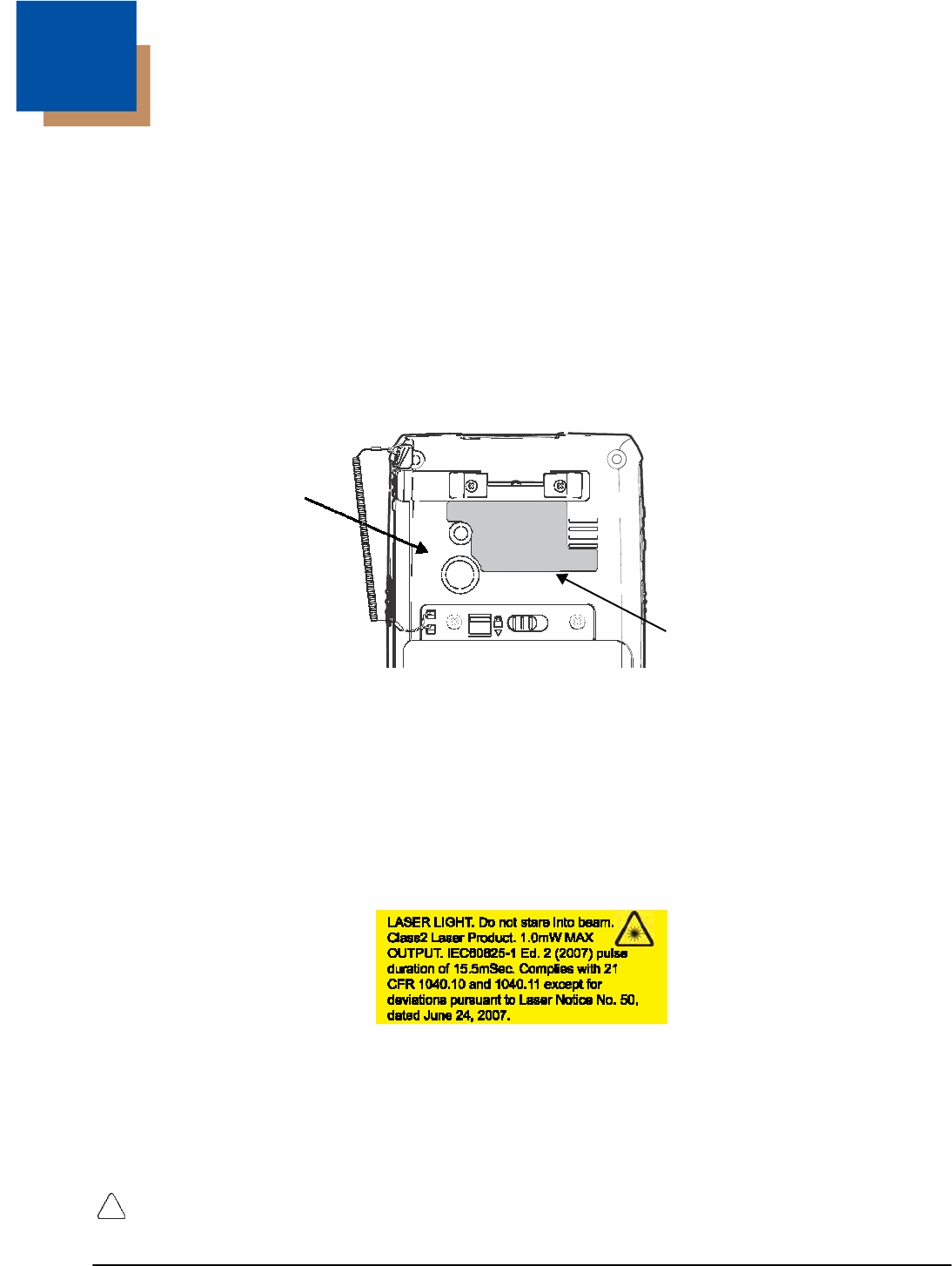
Label Locations
7800 Back Panel
Compliance
Label
Model Number, Serial Number and IMEI Labels
The model (item) number, serial number, and international mobile equipment identity (IMEI) number for
the terminal are located on labels affixed to the walls of the battery well.
Laser Safety Label
If the following label is attached to your product, it indicates the product contains an engine with a laser
aimer:
Image Engines with Integrated Laser Aimers
Laser Safety Statement
This device has been tested in accordance with and complies with IEC60825-1(Ed. 2.0), EN60825-
1:2007. Complies with 21 CFR 1040.10 and 1040.11, except for deviations pursuant to Laser Notice No.
50, dated June 24, 2007. LASER LIGHT, DO NOT STARE INTO BEAM. CLASS 2 LASER PRODUCT,
1.0 mW MAX OUTPUT: 650nm.
WARNING - Use of controls or adjustments or performance of procedures other than those specified herein
may result in hazardous radiation exposure.

DRAFT COPY 11/11/11
1 - 2
LED Safety
LED Safety Statement
LEDs have been tested and classified as “EXEMPT RISK GROUP” to the Standard: IEC 62471:2006.
CAUTION! Do not view directly with optical instruments.
UL and C-UL Statement
UL and C-UL listed: UL60950-1 2nd Edition, and CSA C22.2 No. 60950-1-07 2nd Edition.
Approvals by Country
Country EMC, Radio, & SAR Safety
U.S.A. FCC Part 15, Subpart B
FCC Part 15, Subpart C, 15.247
FCC Part 15, Subpart E
FCC Part 22H
FCC Part 24E
FCC SAR OET 65 Supplement C
UL60950-1 2nd Edition
Canada
ICES-003 (Class B)
RSS 132
RSS 133
RSS 210
CSA C22.2 No. 60950-1-07,
2nd Edition
European Community/CE
EN300328, EN301893, EN55022,
EN55024, EN301489-1,
EN301489-7/24, EN301489-17,
3GPPTS 51.010-1, EN301511,
EN301908, EN50360, EN50361,
EN50371, EN50392, IEC6220-1,
IEC6220-2, EN300440, 301 389-25
(CDMA 2000)
EN60950-1 2nd Edition
EN60825-1 2nd Edition
International
IEC 60950-1 2nd Edition
IEC 60825-1 2nd Edition
IEC 62471
R&TTE Compliance Statement—802.11a/b/g/n, Bluetooth, and/or GSM
Dolphin RF terminals are in conformity with all essential requirements of the R&TTE Directive (1999/5/
EC).
This product is marked with according to article 12 of the R&TTE Directive. In addition, this
product complies to 2006/95/EC Low Voltage Directive when supplied with the recommended power
supply. Honeywell shall not be liable for use of our product with equipment (i.e., power supplies, personal
computers, etc.) that is not CE marked and does not comply with the Low Voltage Directive.

DRAFT COPY 11/11/11
1 - 3
The equipment is intended for use throughout the European Community; PAN European Frequency
Range: 2.402–2.480 GHz. Restrictions for use in France are as follows:
• Indoor use: Maximum power (EIRP*) of 100 mW for the entire 2.400–2.4835 GHz
• Outdoor use: Maximum power (EIRP*) of 100 mW for the 2.400–2.454 GHz band & maximum power
(EIRP*) of 10 mW for the 2.454–2.483 MGHz band.
• 5Ghz band: UNII (Unlicensed National Information Infrastructure) or band1 (5.150 to 5.250 GHz) is
restricted to indoor use only. Any other use will make the operation of the device illegal.
For further information, please contact:
Honeywell Imaging & Mobility Europe BV
Nijverheidsweg 9
5627 BT Eindhoven
The Netherlands
FCC Requirements
Dolphin RF Terminal—802.11a/b/g/n, Bluetooth, and/or GSM
This device complies with Part 15 of the FCC Rules. Operation is subject to the following two conditions:
(1) this device may not cause harmful interference, and (2) this device must accept any interference
received, including interference that may cause undesired operation.
This equipment has been tested and found to comply with the limits for a Class B digital device pursuant
to Part 15 of the FCC Rules. These limits are designed to provide reasonable protection against harmful
interference in a residential installation. This equipment generates, uses, and can radiate radio
frequency energy and, if not installed and used in accordance with the instructions, may cause harmful
interference to radio communications. However, there is no guarantee that interference will not occur in a
particular installation. If this equipment does cause harmful interference to radio or television reception,
which can be determined by turning the equipment off and on, the user is encouraged to try to correct
the interference by one or more of the following measures:
• Reorient or relocate the receiving antenna.
• Increase the separation between the equipment and receiver.
• Connect the equipment into an outlet on a circuit different from that to which the receiver is connected.
• Consult the dealer or an experienced radio/TV technician for help.
If necessary, the user should consult the dealer or an experienced radio/television technician for
additional suggestions. The user may find the following booklet helpful: “Something About Interference.”
This is available at FCC local regional offices. Our company is not responsible for any radio or television
interference caused by unauthorized modifications of this equipment or the substitution or attachment of
connecting cables and equipment other than those specified by our company. The correction is the
responsibility of the user. Use only shielded data cables with this system.
In accordance with FCC 15.21, changes or modifications not expressly approved by the party
responsible for compliance could void the user’s authority to operate the equipment.
The antenna(s) used for this transmitter must not be co-located or operating in conjunction with any
other antenna or transmitter.
CAUTION! - Any changes or modifications not expressly approved by the grantee of this device could void the user’s
authority to operate the equipment.

DRAFT COPY 11/11/11
1 - 4
Canadian Compliance
This device complies with Industry Canada license-exempt RSS standard(s). Operation is subject to the
following two conditions:
(1) this device may not cause interference, and
(2) this device must accept any interference, including interference that may cause undesired operation of
the device.
This Class B digital apparatus complies with Canadian ICES-003.
This Category II radiocommunication device complies with Industry Canada Standard RSS-310.
Conformité à la règlementation canadienne
Le présent appareil est conforme aux CNR d'Industrie Canada applicables aux appareils radio exempts
de licence. L'exploitation est autorisée aux deux conditions suivantes:
(1) l'appareil ne doit pas produire de brouillage, et
(2) l'utilisateur de l'appareil doit accepter tout brouillage radioélectrique subi, même si le brouillage est
susceptible d'en compromettre le fonctionnement."
Cet appareil numérique de la classe B est conforme à la norme NMB-003 du Canada.
Ce dispositif de radiocommunication de catégorie II respecte la norme CNR-310 d’Industrie Canada.
RF Exposure Information (SAR)
This mobile phone meets the government's requirements for exposure to radio waves. This phone is
designed and manufactured not to exceed the emission limits for exposure to radio frequency (RF)
energy set by the Federal Communications Commission of the U.S. Government.
The exposure standard for wireless mobile phones employs a unit of measurement known as the
Specific Absorption Rate, or SAR. The SAR limit set by the FCC is 1.6W/kg. Tests for SAR are
conducted using standard operating positions accepted by the FCC with the phone transmitting at its
highest certified power level in all tested frequency bands. Although the SAR is determined at the
highest certified power level, the actual SAR level of the phone while operating can be well below the
maximum value. This is because the phone is designed to operate at multiple power levels so as to use
only the poser required to reach the network. In general, the closer you are to a wireless base station
antenna, the lower the power output.
The highest SAR value for the model phone as reported to the FCC when tested for use at the ear is
0.364 W/kg Max. and when worn on the body, as described in this user guide, is 0.568 W/kg Max. (Body-
worn measurements differ among phone models, depending upon available accessories and FCC
requirements.)
While there may be differences between the SAR levels of various phones and at various positions, they
all meet the government requirement.
The FCC has granted an Equipment Authorization for this model phone with all reported SAR levels
evaluated as in compliance with the FCC RF exposure guidelines. SAR information on this model phone
is on file with the FCC and can be found under the Display Grant section of www.fcc.gov/oet/ea/fccid
after searching on FCC ID: HD57800LW.
For body worn operation, this phone has been tested and meets the FCC RF exposure guidelines for
use with an accessory that contains no metal and positions the handset a minimum of 1.5 cm from the
body. Use of other accessories may not ensure compliance with FCC RF exposure guidelines. If you do
not use a body-worn accessory and are not holding the phone at the ear, position the handset a
minimum of 1.5 cm from your body when the phone is switched on.

DRAFT COPY 11/11/11
1 - 5
For European Community Users
Honeywell complies with Directive 2002/96/EC OF THE EUROPEAN PARLIAMENT AND OF THE
COUNCIL of 27 January 2003 on waste electrical and electronic equipment (WEEE); European REACH
Regulation 1907/2006 of 1 June, 2007, and Restriction of Hazardous Substances Directive (RoHS)
2002/95/EC of 1 July 2006.
Waste Electrical and Electronic Equipment Information
This product has required the extraction and use of natural resources for its production. It may contain
hazardous substances that could impact health and the environment, if not properly disposed.
In order to avoid the dissemination of those substances in our environment and to diminish the pressure
on the natural resources, we encourage you to use the appropriate take-back systems for product
disposal. Those systems will reuse or recycle most of the materials of the product you are disposing in a
sound way.
The crossed out wheeled bin symbol informs you that the product should not be disposed of along
with municipal waste and invites you to use the appropriate separate take-back systems for product
disposal. If you need more information on the collection, reuse, and recycling systems, please
contact your local or regional waste administration. You may also contact your supplier for more
information on the environmental performances of this product.
China RoHS
(Names and Content of Hazardous Substances or Elements)
(Toxic and Hazardous Substances or Elements)
(Parts Name)
(Pb) (Hg) (Cd) (Cr
6+
) (PBB) (PBDE)
(Imager) x o o o o o
(PCBA) x o o o o o
(Housing) x o o o o o
(Cables) o o o o o o
(LCD) o o o o o o
(LCD Frame) o o o o o o
(Camera) x o o o o o
(Keypad) o
(Battery) o o o o o o
(Power Adapter) x o o o o o
o: SJ/T11363-2006 (Indicates that this toxic or hazardous substance contained in all of the homogeneous
materials for this part is below the limit requirement in China’s SJ/T11363-2006.)
x: SJ/T11363-2006 (Indicates that this toxic or hazardous substance contained in at least one of the
homogeneous materials for this part is above the limit requirement in China’s SJ/T11363-2006. )
Pacemakers, Hearing Aids and Other Electrically Powered Devices
Most manufacturers of medical devices adhere to the IEC 601-1-2 standard. This standard requires
devices to operate properly in an EM Field with a strength of 3V/m over a frequency range of 26 to
1000MHz. The maximum allowable field strength emitted by the Dolphin terminal is 0.3V/m according to
Subpart B of Part 1 of the FCC rules. Therefore, the RF from the Dolphin terminal has no effect on
medical devices that meet the IEC specification.

DRAFT COPY 11/11/11
1 - 6
Hearing Aid Compatibility (HAC)
The Dolphin 7800 has been tested for hearing aid compatibility. This device has an M3 and T3 rating.
For additional HAC information, including the HAC rating for this product, please refer to
www.honeywellaidc.com.
When some wireless devices are used near some hearing devices such as hearing aids and implants,
users may detect a buzzing or humming noise. Some hearing devices are more immune than others to
this interference noise. Wireless devices may also vary in the amount of interference they generate.
The ratings for compatibility of digital wireless devices with hearing aids are described in the American
National Standards Institute (ANSI) C63.19 standard:
M-Rating: Phones rated M3 or M4 meet FCC requirements and are likely to generate less interference
with hearing devices than phones that are not labeled. M4 is the superior/higher of the two ratings.
T-Rating: Phones rated T3 or T4 meet FCC requirements and are likely to be more usable with hearing
devices' telecoil than unrated phones. T4 is the superior/higher of the two ratings.
The more immune the hearing aid device is, the less likely one is to experience interference noise from
the wireless phone. Hearing aid devices may also be rated. Adding the ratings of the hearing aid and
the phone would determine probable usability:
• Any combined rating equal to or greater than six offers the best use.
• Any combined rating equal to five is considered normal use.
The ratings are not guarantees. Results will vary depending on the user's hearing device and hearing
loss. If your hearing device happens to be vulnerable to interference, you may not be able to use this
device successfully. Trying out this device with your hearing device is the best way to evaluate it for your
personal needs.
This device has been tested and rated for use with hearing aids for some of the wireless technologies
that it utilizes. However, there may be some newer wireless technologies used in this phone that have
not been tested yet for use with hearing aids. It is important to try the different features of this phone
thoroughly and in different locations, using your hearing aid or cochlear implant, to determine if you hear
any interfering noise. Consult your service provider or the manufacturer of this phone for information on
hearing aid compatibility.
Microwaves
The radio in the Dolphin RF terminal operates on the same frequency band as a microwave oven.
Therefore, if you use a microwave within range of the Dolphin RF terminal you may notice performance
degradation in your wireless network. However, both your microwave and your wireless network will
continue to function.
2 - 1
2 DRAFT COPY 11/11/11
Getting
Started
Out of the Box
Verify that the carton contains the following items:
• Dolphin mobile computer (the terminal)
• Main battery pack
• Quick Start Guide
If you ordered accessories for your terminals, verify that they are also included with the order. Be sure to
keep the original packaging in the event that the Dolphin terminal should need to be returned for service.
For details, see Product Service and Repair on page 18-1.
Initial Setup for Dolphin 7800 Terminals
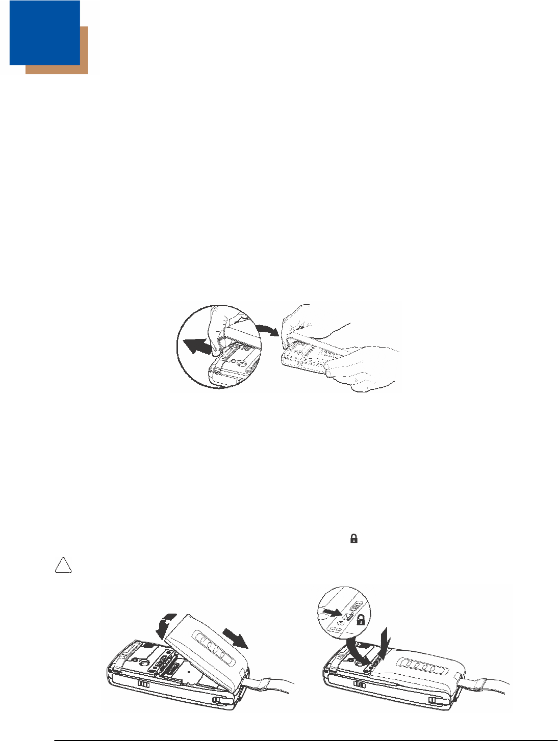
Step 1. Release the Hand Strap
Step 2. Install the Main Battery Pack
Note: Before installing the main battery pack, read the Guidelines for Battery Pack Use and Disposal on page 3-13.
Dolphin 7800 model terminals are designed for use with standard battery pack model 7800-BTSC (Li-ion
3.7 V, 8.9 watt hour) and extended battery pack models 7800-BTXC and 7800-BTXCW (Li-ion 3.7 V,
14.8 watt hour) manufactured for Honeywell International Inc.
The terminal is shipped with the battery packaged separate from the unit. Perform the steps illustrated
below to install the main battery. For information on how to remove the battery, see Replacing the Main
Battery Pack on page 2-4.
Note: The terminal does not power ON unless the battery is locked .
Ensure all components are dry prior to placing the battery in the terminal. Mating wet components may cause
damage not covered by the warranty.
4
2 1 3
DRAFT COPY 11/11/11
2 - 2
Step 3. Charge the Main and Backup Batteries
The power supply for Dolphin terminals consists of two types of battery power: the main battery pack
that is accessible from the back panel, and the backup battery that resides inside the terminal. The main
battery powers the terminal. The internal backup battery charges off the main battery and maintains the
application data stored in RAM memory for up to 5 minutes when the terminal’s main battery pack is
completely discharged or removed.
Dolphin 7800 terminals are designed for use with the following 7800 charging devices and cables:
7800-HB, 7800-EHB, 7800-NB, 7800-CB, 7800-DEX, 7800-MC, 7800-MB, 7800-USB, and 7800-USBH.
See Chapters 12-17 for additional information on the individual device requirements.
Before Initial Use
Terminals are shipped with both batteries discharged of all power. The initial charging time for the main
battery pack is 4 hours for the standard battery pack or 6 hours for the extended battery pack. Connect
the terminal to one of the 7800 series charging peripherals to charge; see Peripherals for the 7800 on
page 3-3.
Note: Honeywell recommends charging the Dolphin terminal for at least 24 hours prior to initial use to ensure the
internal backup battery is fully charged.
We recommend use of Honeywell peripherals, power cables, and power adapters. Use of any non-Honeywell
peripherals, cables, or power adapters may cause damage not covered by the warranty.
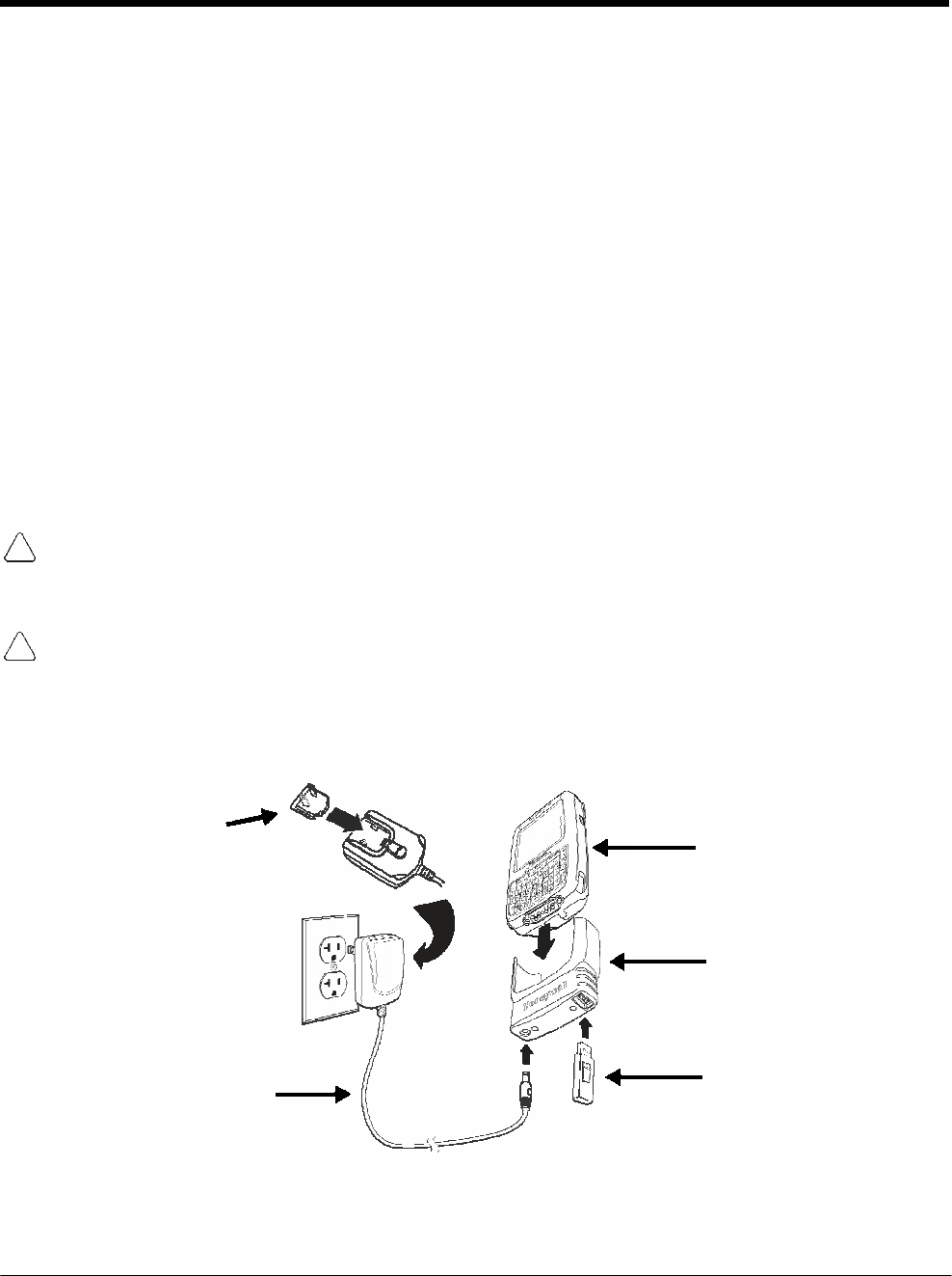
Charging Using the Communication Cable
Ensure all components are dry prior to mating terminals/batteries with peripheral devices. Mating wet
components may cause damage not covered by the warranty.
Client Device Communication Cable (7800-USB)
Use only a UL Listed power supply, which has been qualified by Honeywell with an output rated at 5VDC
and 3A with the device.
3 Dolphin 7800 Models
1
Charging
Cup
4 2
Power Cable
DRAFT COPY 11/11/11
2 - 3
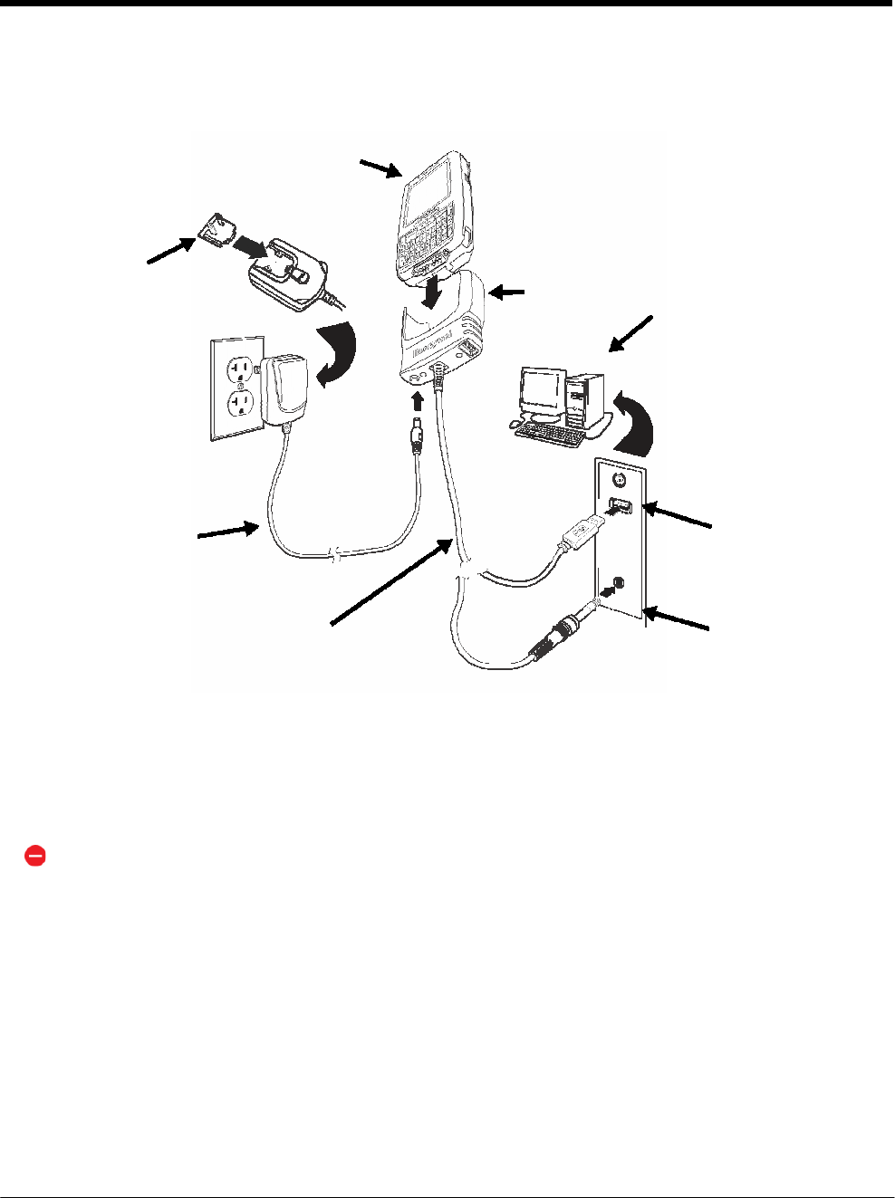
Host Device Communication Cable (7800-USBH, 7800-DEX)
Use only a UL Listed power supply, which has been qualified by Honeywell with an output rated at 5VDC
and 3A with the device.
4
Plug Adapter
Dolphin 7800
1
Cable Cup
Host Device
5 3
2
Power Cable
USB
or
COMM
Cable
DEX
Battery Error Notification
If your terminal displays the following indicators, replace the main battery pack with a Honeywell battery
pack. For information on how to remove the main battery pack from the terminal, see Replacing the Main
Battery Pack on page 2-4.
• An “Authentication Error” pop up window appears during startup.
• appears in the Title bar at the top of the touch screen.
• The General Notification LED flashes red.
• A Notification appears on the Tile bar at the bottom of the touch screen.
Step 4. Boot the Terminal
The terminal begins booting as soon as power is applied. Do NOT press any keys or interrupt the boot
process. When the boot process is complete, the Home screen appears, and the terminal is ready for
use.
DRAFT COPY 11/11/11
2 - 4
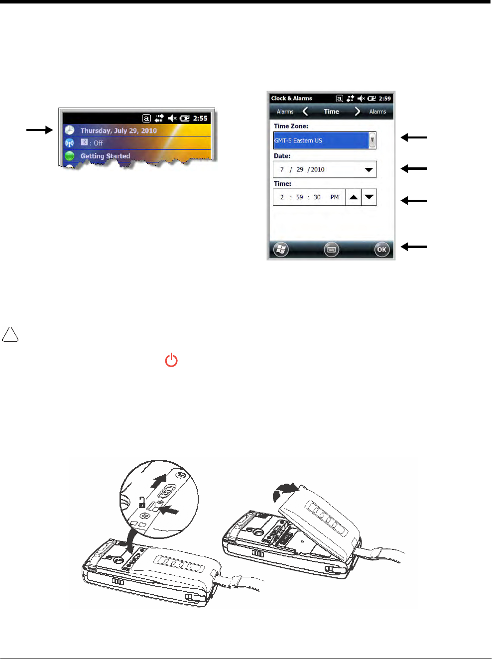
Step 5. Set the Time Zone, Time, and Date
On the Home screen, tap the line that displays the time and date. When the Clock & Alarms screen
appears, tap the arrow to the right of the time zone to open the drop down menu. Select the appropiate
time zone from the menu. Set the correct time and date in the remaining fields and tap OK to save.
Replacing the Main Battery Pack
Note: Before replacing the main battery pack, read the Guidelines for Battery Pack Use and Disposal on page 3-13.
Ensure all components are dry prior to mating terminals/batteries with peripheral devices. Mating
wet
components may cause damage not covered by the warranty.
1. Press and hold the Power key for approximately 5 seconds to put the terminal in Suspend Mode
(see page 2-11).
2. Release the hand strap near the speaker on the back panel of the terminal.
3. Unlock the battery by sliding the latch away from the battery.
4. Wait at least 3 seconds, then slide the battery release button away from the stylus slot.
5. Remove the battery.
4 5
3
DRAFT COPY 11/11/11
2 - 5
6. Insert the new battery and apply gentle pressure to engage the latch.
Note: Make sure the stylus tether is not caught under the battery during installation.
7. Lock the battery by sliding the latch toward the battery pack.
Note: The terminal does not power ON unless the battery is locked.
8. Reattach the hand strap.
9. Press the Power key or the SCAN key to wake the terminal from Suspend Mode (see page 2-11).
We recommend use of Honeywell Li-ion battery packs. Use of any non-Honeywell battery may result in
damage not covered by the warranty.
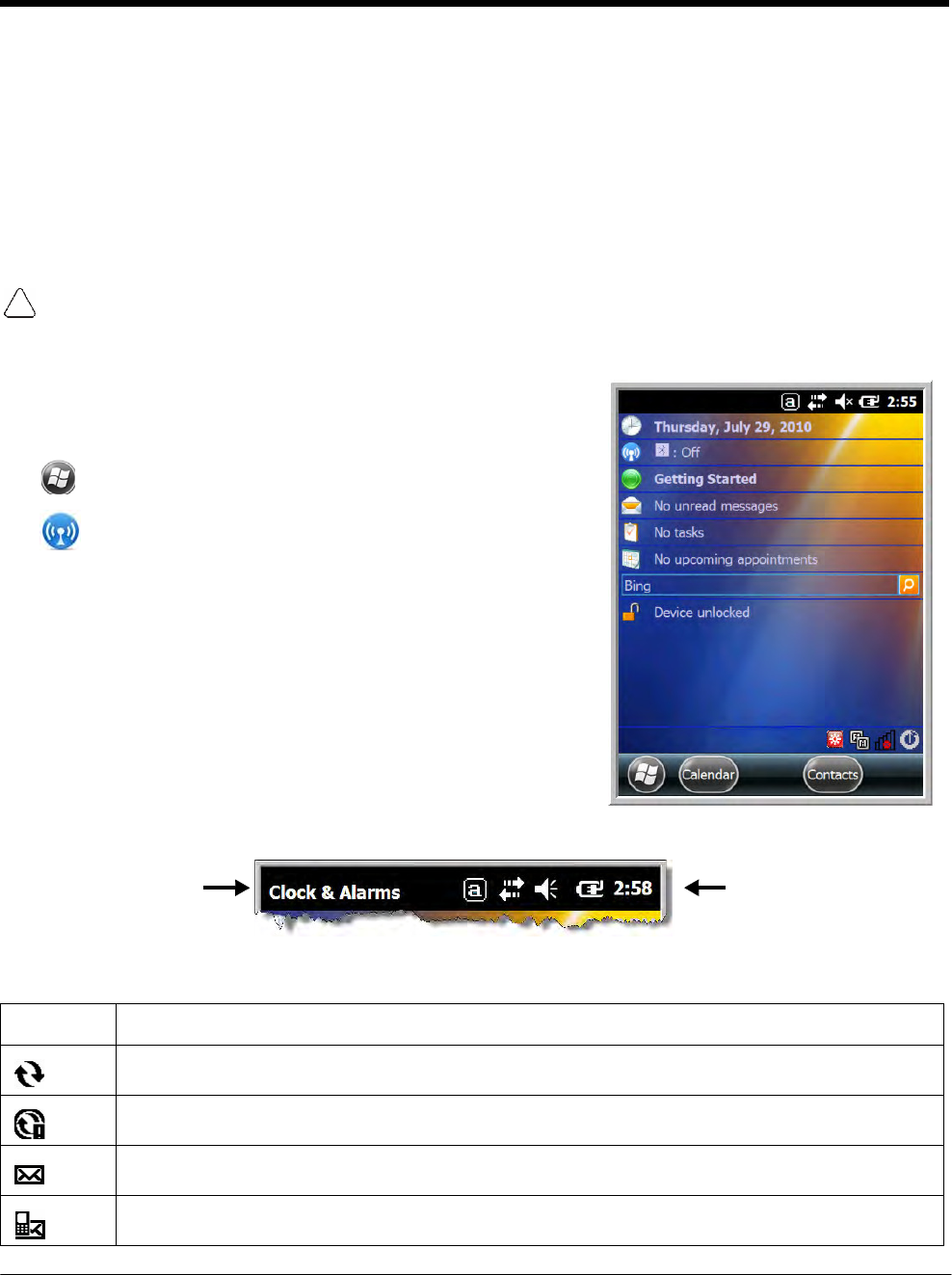
Home Screen
After the Dolphin terminal initializes the first time, you see the
Home screen.
Tap to reach the Start screen from the Home screen. T
ap
to access the Dolphin Wireless Manager (see page
8-4) from the home screen.
Title Bar
The Title bar, located at the top of the screen, displays the
active program, the status of various system functions, and
the current time. Tapping on the title bar provides access to
the Horizontal Scroll. The scroll provides access to additional
programs and application screens. For additional information,
see Horizontal Scroll on page 2-8.
Text here indicates
the active program. Icons here indicate the
status of various system
functions.
Icons in the Title Bar
Indicator Meaning
Synchronizing data
The terminal could not synchronize data with the workstation via ActiveSync.
New e-mail
New text message

DRAFT COPY 11/11/11
2 - 6
Icons in the Title Bar
Indicator Meaning
New voicemail
New instant message
Vibrate on
Ringer off
Speakerphone on
Voice call in progress
Calls are forwarded
Call on hold
Missed call
Data call in progress
A battery error has occurred. Replace the main battery pack with a Honeywell Li-ion battery pack.
Battery is has a full charge
Battery has a high charge
Battery has a medium charge
Battery has a low charge
Battery has a very low charge and requires charging
Terminal is running on external power. If a battery pack is installed, the battery is charging in the
background.
The terminal is not connected to external power. A battery is installed, but is defective; specifically,
its charge level cannot be measured.
No SIM card is installed
Active network connection
No active network connection

DRAFT COPY 11/11/11
2 - 7
Icons in the Title Bar
Indicator Meaning
GPRS available
GPRS connecting
GPRS in use
HSDPA available
HSDPA connecting
HSDPA in use
EDGE available
EDGE connecting
EDGE in use
UMTS available
UMTS connecting
UMTS in use
Radio is off
The radio is not connected to a network.
The radio is connected. The bars indicate the signal strength.
No radio signal
The terminal is searching for a signal.
Wi-Fi is on, but device is not connected
Wi-Fi data call
Pending alarm
Bluetooth
DRAFT COPY 11/11/11
2 - 8
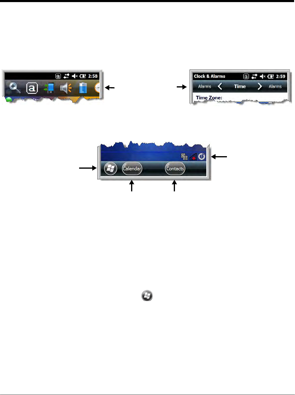
Horizontal Scroll
The Horizontal Scroll, located at the top of most application windows, provides access to additional
application screens. You can flick left or right on the scroll or tap each label on the scroll, until you get to
the desired screen. Tapping a label to the left or right of the center item brings new labels into view.
Note: Tap the Title bar to access the horizontal scroll if it is not visible on the screen.
The content of the
Horizontal scroll
changes according to
the open
application.
Tile Bar
The Tile bar is located at the bottom of application windows.
The Tile bar displays icons you
use to open and close screens,
menues, and features.
The Task tray displays icons
for programs running in the
background.
The icons change according to the open application.
Pop-Up Menus
With pop-up menus, you can quickly choose an action for a selected item. To access a pop-up menu, tap
and hold the stylus on the item name of the action you want to perform. When the menu appears, lift the
stylus, and tap the action you want to perform.
Tap anywhere outside the menu to close the menu without performing an action.
Selecting Programs
To see the programs loaded on your terminal, tap to access the Start Menu. To open a
program, tap once on the program icon. To reposition an icon on the Start Menu, tap and hold the stylus
on the icon, then drag the icon to the desired position.
DRAFT COPY 11/11/11
2 - 9
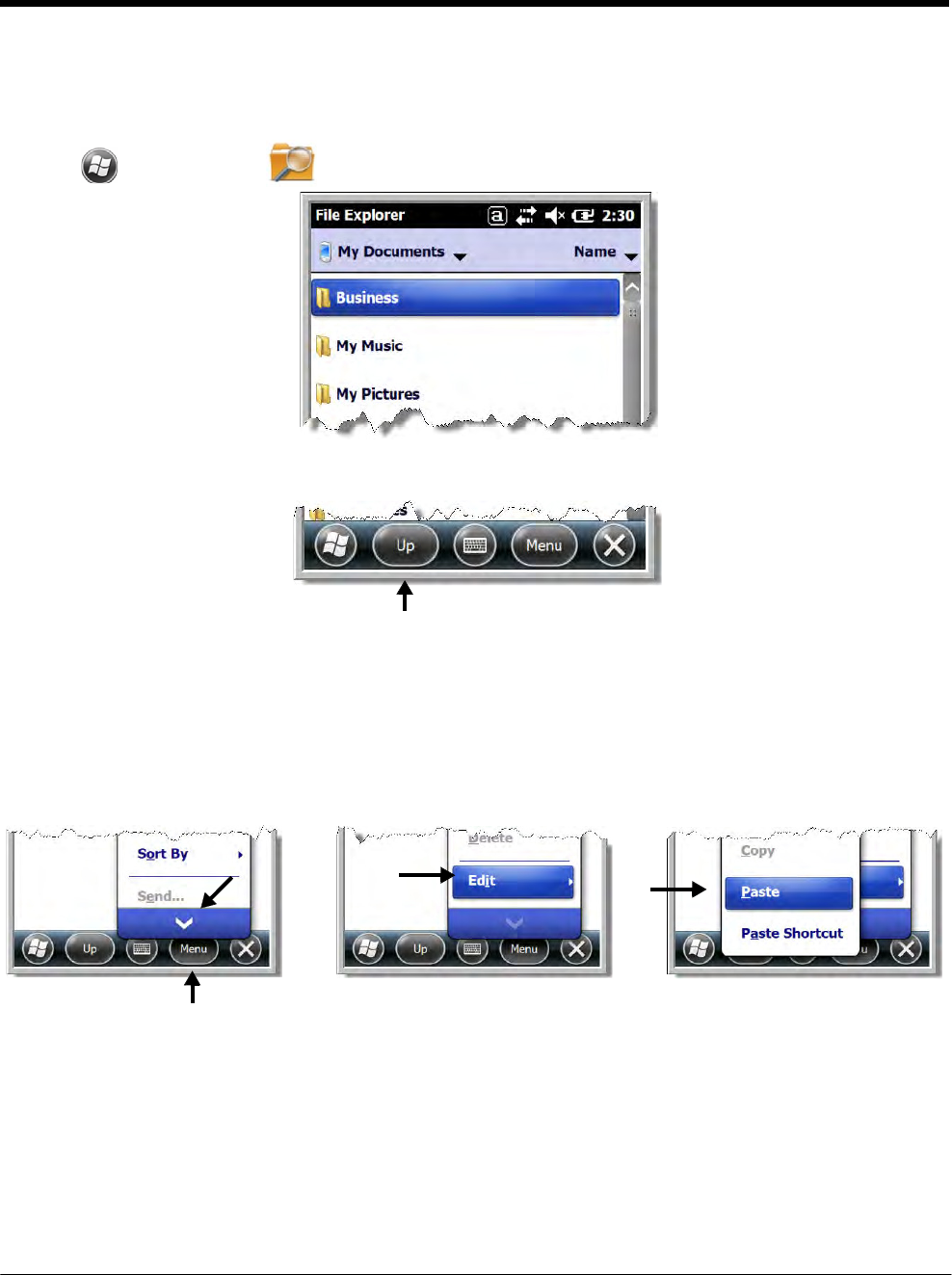
File Explorer
You can also use the File Explorer to find files and organize these files into folders.
1. Tap > File Explorer .
2. Tap the Up button at the bottom of the screen to move up one level in the directory.
3. You can move files in File Explorer by tapping and holding on the item you want to move, then
tapping Cut or Copy on popup menu.
4. Navigate to the folder you want to move the file to, then tap and hold a blank area of the window.
5. Tap Paste on the pop-up menu.
Note: If there is no blank space available in the window, tap Menu on the command bar, navigate to the end of the
menu using the down arrow, then tap Edit > Paste.

DRAFT COPY 11/11/11
2 - 10
File Provisioning on the 7800
\IPSM\Honeywell
The IPSM folder is the only partition on the 7800 that persists across a kernel upgrade (*.UPG file exten-
sion). During a kernel upgrade, files are automatically copied from the \IPSM\Honeywell\Autoin-
stall folder and then installed in the \Honeywell (root file system) folder as part of the upgrade
process.
\IPSM\Honeywell\AutoInstall
The files in the IPSM\Honeywell\AutoInstall folder are only installed when a factory reset or ker-
nel upgrade occurs. Once the files are installed, they persist through hard and soft resets. If a file is
added to the folder and a hard or soft reset is performed, it will have no effect. If a program is manually
removed using the Remove Programs application (see page 7-16), then the program is not automatically
re-installed on a hard or soft reset.
\Honeywell
The Honeywell partition or root file system partition is persistent over a Hard Reset, Soft Reset, and the
removal of the battery pack or the removal of AC power. However, during a kernel upgrade the root file
system is reformatted so all data in the folder is deleted and replaced by any files in the \IPSM\Honey-
well\AutoInstall folder as part of the upgrade process.
To prevent data loss, back up all user data to an SD card or external memory device before perform-
ing an upgrade.
\Honeywell\AutoInstall
If you run a CAB file from within the \Honeywell\AutoInstall (user store) folder, after the program
has been installed, the CAB file will be deleted from the User Store. The program remains installed
through all successive Hard and Soft resets.
If you want the program to be part of the Autoinstall that occurs after a factory reset or software upgrade,
paste the program file(s) in both the \IPSM\Honeywell\Autoinstall folder and the
\Honeywell\Autoinstall.
Contact a Honeywell technical support representative for information on how to perform a factory reset
or for information on available software upgrades for your Dolphin terminal. For contact information, see
Customer Support on page 18-1. or go to www.honeywellaidc.com.
To prevent data loss, back up all user data to an SD card or external memory device before perform-
ing an upgrade.
Search
The Search feature helps you quickly locate information. Tap > Search Phone .
Enter the text you want to find, select a data type, and then tap Search. Select Larger than 64 KB in the
Type drop-down field to quickly find information that is taking up storage space.

DRAFT COPY 11/11/11
2 - 11
Resetting the Terminal
There are three types of system resets: a soft reset, a hard reset, or a factory reset. The soft and hard
resets preserve all data stored in the file system. Contact a Honeywell technical support representative
for more information on how to perform a factory reset.
Soft Reset (Warm Boot)
A soft reset re-boots the device and preserves any objects created in RAM. You would perform a soft
reset when: the terminal fails to respond, after installing some software applications, or after making
changes to certain system settings, such as network cards.
1. Press and hold the BLUE + END keys for approximately 5 seconds.
2. The general notification LED flashes orange then green for approximately 3 seconds as the terminal
resets.
3. When the reset is complete, the Home screen displays.
Hard Reset (Cold Boot)
A hard reset re-boots the device and closes any open applications running in RAM at the time of the
reset.
1. Press and hold the BLUE + SEND keys for approximately 5 seconds.
2. The general notification LED flashes orange then green for approximately 3 seconds as the terminal
resets.
3. The terminal re-initializes.
Factory Reset
Contact a Honeywell technical support representative for information on how to perform a factory reset.
For contact information, see Customer Support on page 18-1.
Suspend Mode
The terminal goes into Suspend Mode automatically when the terminal is inactive for a programmed
period of time. You can program this time on the Advance tab of the Power System Setting; see Power
on page 7-15.
To put the terminal into Suspend Mode manually, press and hold the POWER key for approximately
5 seconds until the touch screen turns off.
To wake the terminal from Suspend Mode, press the POWER key or SCAN key.
Note: You should always put the terminal in suspend mode before removing the battery. For information on
removing the battery, see Replacing the Main Battery Pack on page 2-4.

DRAFT COPY 11/11/11
2 - 12

3 - 1
3 DRAFT COPY 11/11/11
Hardware
Overview
Standard Configurations for the 7800
WLAN & WPAN
• Microsoft Windows Embedded Handheld
6.5 Classic
• 800MHz TI OMAP Processor
• 256MB RAM X 512MB Flash
• Six keyboard options
• 3.7V Li-ion standard battery pack or
extended rechargeable battery pack
• Adaptus Imaging Technology: N5603ER/
SR/HD or N5600ER/SR/HD image engines
• 802.11a/b/g/n and Bluetooth
WLAN, WPAN &
Camera
• Microsoft Windows Embedded Handheld
6.5
Classic
• 800MHz TI OMAP Processor
• 256MB RAM X 512MB Flash
• Six keyboard options
• 3.7V Li-ion standard battery pack or
extended rechargeable battery pack
• Adaptus Imaging Technology: N5603ER/
SR/HD or N5600ER/SR/HD image engines
• 802.11a/b/g/n and Bluetooth
• 3.0 megapixel auto control color camera
WLAN, WPAN, with GPS
• Microsoft Windows Embedded Handheld
6.5
Classic
• 800MHz TI OMAP Processor
• 256MB RAM X 512MB Flash
• Six keyboard options
• 3.7V Li-ion standard battery pack or
extended rechargeable battery pack
• Adaptus Imaging Technology: N5603ER/
SR/HD or N5600ER/SR/HD image engines
• 802.11a/b/g/n and Bluetooth
• GPS
WLAN, WPAN, with GPS & Camera
• Microsoft Windows Embedded Handheld
6.5 Classic
• 800MHz TI OMAP Processor
• 256MB RAM X 512MB Flash
• Six keyboard options
• 3.7V Li-ion standard battery pack or
extended rechargeable battery pack
• Adaptus Imaging Technology: N5603ER/
SR/HD or N5600ER/SR/HD image engines
• 802.11a/b/g/n and Bluetooth
• GPS
• 3.0 megapixel auto control color camera
WLAN, WPAN, & WWAN
• Microsoft Windows Embedded Handheld
6.5 Professional
• 800MHz TI OMAP Processor
• 256MB RAM X 512MB Flash
• Six keyboard options
• 3.7V Li-ion extended rechargeable battery
pack
• Adaptus Imaging Technology: N5603ER/
SR/HD or N5600ER/SR/HD image engines
• 802.11a/b/g/n, Bluetooth, and GSM/
HSPA+
WLAN, WPAN, & WWAN with GPS
• Microsoft Windows Embedded Handheld
6.5 Professional
• 800MHz TI OMAP Processor
• 256MB RAM X 512MB Flash
• Six keyboard options
• 3.7V Li-ion extended rechargeable battery
pack
• Adaptus Imaging Technology: N5603ER/
SR/HD or N5600ER/SR/HD image engines
• 802.11a/b/g/n, Bluetooth, and GSM/
HSPA+
• GPS

DRAFT COPY 11/11/11
3 - 2
WLAN, WPAN, WWAN with GPS & Camera
• Microsoft Windows Embedded Handheld
6.5 Professional
• 800MHz TI OMAP Processor
• 256MB RAM X 512MB Flash
• Six keyboard options
• 3.7V Li-ion extended rechargeable battery
pack
• Adaptus Imaging Technology: N5603ER/
SR/HD or N5600ER/SR/HD image engines
• 802.11a/b/g/n, Bluetooth, and GSM/
HSPA+
• GPS
• 3.0 megapixel auto control color camera
WLAN, WPAN, & WWAN
• Microsoft Windows Embedded Handheld
6.5 Professional
• 800MHz TI OMAP Processor
• 256MB RAM X 512MB Flash
• Six keyboard options
• 3.7V Li-ion extended rechargeable battery
pack
• Adaptus Imaging Technology: N5603ER/
SR/HD or N5600ER/SR/HD image engines
• 802.11a/b/g/n, Bluetooth, and GSM/CDMA
WLAN, WPAN, & WWAN with GPS
• Microsoft Windows Embedded Handheld
6.5 Classic
• 800MHz TI OMAP Processor
• 256MB RAM X 512MB Flash
• Six keyboard options
• 3.7V Li-ion extended rechargeable battery
pack
• Adaptus Imaging Technology: N5603ER/
SR/HD or N5600ER/SR/HD image engines
• 802.11a/b/g/n, Bluetooth, and GSM/CDMA
• GPS
WLAN, WPAN, WWAN with GPS & Camera
• Microsoft Windows Embedded Handheld
6.5 Classic
• 800MHz TI OMAP Processor
• 256MB RAM X 512MB Flash
• Six keyboard options
• 3.7V Li-ion extended rechargeable battery
pack
• Adaptus Imaging Technology: N5603ER/
SR/HD or N5600ER/SR/HD image engines
• 802.11a/b/g/n, Bluetooth, and GSM/
HSPA+ or GSM/CDMA
• GPS
• 3.0 megapixel auto control color camera
Some configurations of the 7800 terminal are available with an external housing made of plastic that is
specifically designed for the healthcare industry. For more information, see Healthcare Housing on page
3-11.

DRAFT COPY 11/11/11
3 - 3
Peripherals for the 7800
Each of the following items is sold separately to enhance the capabilities of your Dolphin terminal.
Dolphin 7800 HomeBase™ Device
The Dolphin 7800 HomeBase device is a charging and communication cradle equipped with a USB host
port that is Hi-Speed 2.0v compliant, which enables the terminal to interface with the majority of PC-
based enterprise systems. This device also contains an auxiliary battery well that charges a spare Hon-
eywell standard or extended battery pack.
For more information, see Dolphin 7800 HomeBase Device (Model 7800-HB) on page 12-1.
Dolphin 7800 Mobile Base™ Device
The Dolphin 7800 Mobile Base device is a charging and communication cradle designed specifically for
in-premise and in-transit data collection applications. It features a flexible mounting bracket and a ciga-
rette lighter adapter to adapt it to your environment.
For more information, see Dolphin 7800 Mobile Base Device (Model 7800-MB) on page 14-1.
Dolphin 7800 eBase™ Device
The Dolphin 7800 Ethernet (eBase) device enables a single 7800 mobile computer to communicate with
a host device over an Ethernet network. In addition, the ebase is equipped with a USB host port that is
Hi-Speed 2.0v compliant, which enables the terminal to interface with the majority of PC-based enter-
prise systems. This device also contains an auxiliary battery well that charges a spare Honeywell stan-
dard or extended battery pack.
For more information, see Dolphin 7800 eBase Device (Model 7800-EHB) on page 13-1.
Dolphin 7800 Net Base™ Device
The Dolphin 7800 Net Base device enables up to four 7800 mobile computers to communicate with a
host device over an Ethernet network. In addition, the Net Base provides a second RJ45 Ethernet port
for connection to an additional device such as a printer, workstation, eBase, or another Net Base.
For more information, see Dolphin 7800 Net Base Device (Model 7800-NB) on page 16-1.
Dolphin 7800 ChargeBase
The Dolphin 7800 ChargeBase is a 4-slot charging cradle that holds, powers, and charges terminals.
For more information, see Dolphin 7800 ChargeBase Device (Model 7800-CB) on page 15-1.
Dolphin 7800 QuadCharger™ Device
The Dolphin 7800 QuadCharger device is a 4-slot charging station for Dolphin 7800 standard or
extended battery packs.
For more information, see Dolphin 7800 QuadCharger Device (Model 7800-QC) on page 17-1.

DRAFT COPY 11/11/11
3 - 4
Accessories for the 7800
Each of the following items is sold separately to enhance your terminal’s capabilities.
Note: When using accessories where the terminal is worn on the body, the terminal’s touch panel must face away
from the body.
Dolphin 7800 Mobile Charger
The Dolphin 7800 Mobile Charger is a charging cable that connects the terminal directly to a 12 Volt DC
power source, such as a cigarette lighter port inside a vehicle, eliminating the need for a cradle. Intelli-
gent battery technology on-board the terminal ensures proper charging. The Dolphin 7800 Mobile Char-
ger is an ideal low-cost charging solution for in-transit mobile applications.
Communication/Charging Cables
Dolphin communication/charging cable kits are an all-in-one solution for mobile applications. Each cable
kit powers the terminal, charges its main battery, and communicates with host or peripheral devices with-
out the need for a cradle. Cable kits can support USB client or USB host communications.
Storage Holster
The storage holster provides convenient storage for the Dolphin terminal in mobile environments. The
holsters feature a belt loop to secure the holster to a belt.
Stylus Kits
Each Dolphin is shipped with a stylus and a stylus tether used to secure the stylus to the terminal to pre-
vent loss. Kits containing three styli and three tethers are available for purchase.
Battery Pack
The rechargable battery pack provides the main power for the terminal. For more information, see
Batteries on page 3-12.
DRAFT COPY 11/11/11
3 - 5
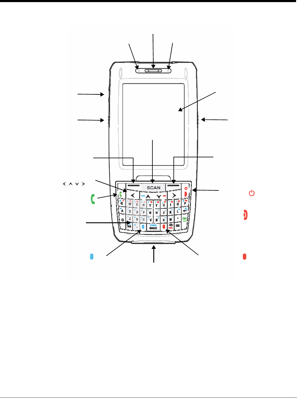
Front Panel: 7800
Charge Indicator LED
Front Speaker
General Notification LED
Volume Control Button Touch Panel Display
Left Scan/Image Button Right Scan/Image Button
SCAN
Key
Left Soft
Key
Right Soft Key
Navigation Keys
Send
Call
Microphone
Power Key
or
End Call
Blue Modifier Key
I/O Connector
Red Modifier Key
Note: Your Dolphin model may differ from the model illustrated; however, the features noted are standard for all
7800 models unless otherwise indicated. For a complete overview of the optional keyboards available for the
7800, see Using the Keyboards on page 6-1.
For a description of each callout, see see Front Panel Features for the 7800 on page 3-6.

DRAFT COPY 11/11/11
3 - 6
Front Panel Features for the 7800
Blue Modifier Key
See Using the Modifier Keys on page 6-3.
Charge Indicator LED
The light emitting diode (LED) located above the top left corner of the LCD display illuminates
when the Power Tools BattMon application is enabled and the device is on AC charge. For
more information, consult the Dolphin Power Tools User’s Guide for Windows Embedded
Handheld 6.5.
Front Speaker
The front speaker is the receiver for handset voice calls. See GSM/HSPA+ Global Radio
Dolphin Models on page 9-3.
General Notification LED
The light emitting diode (LED) located above the top right corner of the LCD display flashes
and illuminates during resets, scanning/imaging, and taking a picture. This LED can be
programmed by various software applications.
Left Scan/Image Button
By default, the Left Button triggers the scanner/imager. You can reassign the button to launch
applications or execute commands. For additional information, see Changing Button
Assignments on page 7-4.
Microphone
The integrated microphone that provides audio input for handset and speakerphone voice
calls. See Voice Communication on page 9-3.
Navigation Keys
The centrally located navigation keys enable you to move and position the cursor through
software programs. The up and down arrows are programmed to perform specific functions
when pressed in combination with the Blue and Red modifier keys. For more details, see Using
the Navigation Keys on page 6-3.
Power Key
The Power key, located in the upper right corner of the keypad, puts the terminal in Suspend
Mode or wakes the terminal from Suspend Mode. See Suspend Mode on page 2-11. The key
is also used to end/diconnect a phone calls.
There are multiple keyboard options available for the 7800. For a complete overview of each
keyboard, see Using the Keyboards on page 6-1.
Red Modifier Key
See Using the Modifier Keys on page 6-3.
Right Scan/Image Button
By default, the Right Button triggers the scanner/imager. You can reassign the button to launch
applications or execute commands. For additional information, see Changing Button
Assignments on page 7-4.

DRAFT COPY 11/11/11
3 - 7
SCAN Key
The SCAN key is centrally located for easy access with the right or left hand. When pressed,
the SCAN key activates the scanner/imager. The SCAN key also functions as a system wake-
up control for the terminal.
Touch Panel Display
The color 3.7 inch 64k color liquid crystal display (LCD) touch panel is covered with an
industrial, protective lens for greater durability. The video graphic array (VGA) display
resolution is 480 X 640.
The touch panel backlight illuminates when the screen is touched, but not when the Backlight
key is pressed. For more information, see Backlight on page 7-9.
The touch panel can be activated by the stylus (included with the terminal). For more
information, see Using the Touch Panel on page 3-11.
Volume Control Button
Press the top or bottom of the volume button to raise or lower the volume of the active speaker.
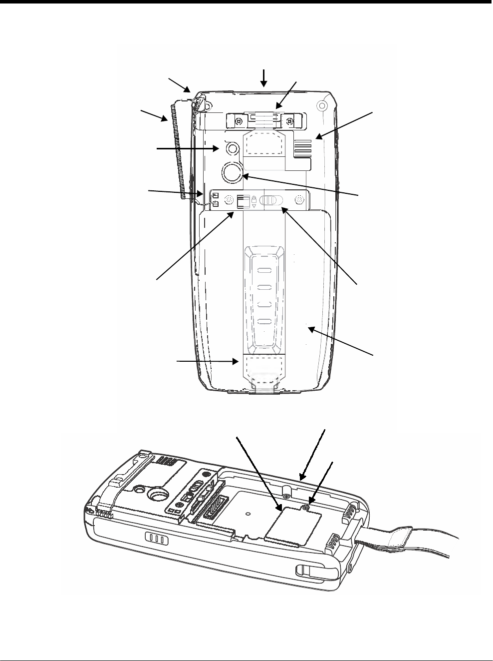
DRAFT COPY 11/11/11
3 - 8
Back Panel: 7800
Stylus/Stylus Slot
Image/Scan Engine Window*
Hand Strap Hook
Stylus Tether Rear Speaker
Flashlight/Camera Flash
Fastener for the Stylus Tether
Color Camera
Battery
Lock
Battery Release Button
Hand
Strap
Battery
Memory Card Socket and SIM Card Socket
(located under protective shield)
Battery Well
Memory/SIM Shield Screws, Qty.
2
* LED and Laser Aimer Aperture
Note: Your Dolphin model may differ from the model illustrated; however, the features noted are standard for all
7800 models unless otherwise indicated.
For a description of each callout, see Back Panel Features for the 7800 on page 3-9.

DRAFT COPY 11/11/11
3 - 9
Back Panel Features for the 7800
Battery
Dolphin 7800 model terminals are designed for use with standard battery pack model 7800-
BTSC (Li-ion 3.7 V, 8.9 watt hour) and extended battery pack models 7800-BTXC and 7800-
BTXCW (Li-ion 3.7 V, 14.8 watt hour) manufactured for Honeywell International Inc. For
information on how to remove the battery, see Replacing the Main Battery Pack on page 2-4.
Battery Lock
The Battery Lock allows the user to lock the battery pack in place preventing battery loss due
to accidental activation of the battery release. The battery release button has no effect if the
Battery lock is engaged. The terminal does not power ON unless the Battery Lock is engaged.
Battery Release Button
The Battery Release Button ejects one end the battery from the terminal for easy battery
removal. The battery release button has no effect if the Battery lock is engaged. For
information on how to remove the battery, see Replacing the Main Battery Pack on page 2-4.
Color Camera
The 3.0-Megapixels Resolution color camera provides easy picture capture with Automated
Camera Control (ACC). Additional features include automated picture profiles and an
Application Programming Interface (API).
Fastener for the Stylus Tether
The Stylus Tether helps prevent accidental loss when the stylus is not stored in the stylus slot.
A stylus tether is a coiled, elastic cord that tethers the stylus to the terminal. Secure one end
of the cord to the back panel of the terminal and the other end to the stylus.
Flashlight/Camera Flash
The flashlight/camera flash is located on the back panel of the terminal. When used as a
Flashlight, press the Red key + key to turn the flashlight ON or OFF. When used as a
Camera Flash with the terminal’s color camera, the flash is controlled by the camera
application.
Hand Strap
The 7800 comes with an elastic hand strap. One end of the hand strap can be released to
provide easy access to the battery pack. The hand strap release hook is located near the
speaker on the back panel of the terminal.
Image/Scan Engine Window
The available image engines read and decode linear, stacked linear (e.g., PDF417), and 2D
matrix bar code symbologies. Some of the available engine models contain a laser aimer for
greater accuracy. The laser apertures for the imaging engines’ laser aimers are contained
behind this window. For more details, see Using the Scan Image Engine on page 4-1.
Memory Card Socket and SIM Card Socket
The memory card socket provides the user with the option to expand the terminal’s memory
capacity using industry-standard microSD or microSDHC memory interfaces. The expansion
socket is located under the main battery in the battery well. The card socket for the Subscriber
Identity Module (SIM) is also located under the main battery in the battery well.
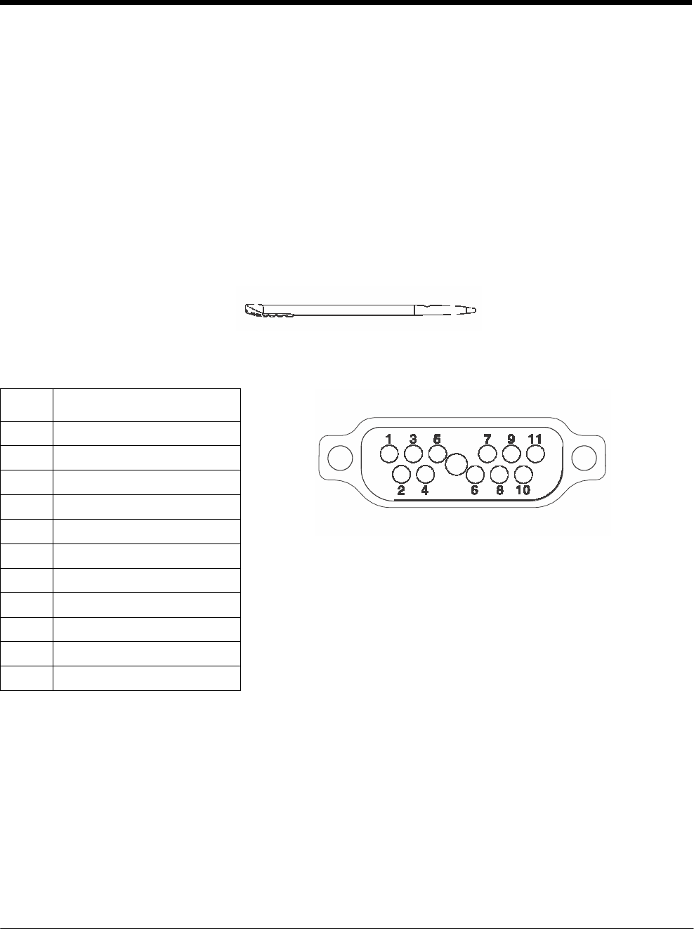
DRAFT COPY 11/11/11
3 - 10
When the protective SIM/memory card cover and battery pack are properly installed, the cards
are sealed against moisture and particle intrusion, read/write data is stored securely, and the
terminal’s environmental rating is preserved; see Installing a SIM Card and/or Memory Card
on page 3-16.
Rear Speaker
The integrated rear speaker sounds audio signals as you scan bar code labels and enter data.
The integrated speaker also supports playback of wave and MP3 files, software mixer, and
Speakerphone for WWAN/GSM audio. The operating frequency range is 600-3000Hz at
>90dB.
Stylus/Stylus Slot
The stylus is used to operate the touch panel. The back panel of the terminal features a storage
slot to hold the stylus when not in use. The stylus features a special tip for added accuracy and
ease of use.
Bottom Panel: 7800
Pin Description
1
PWR
2
PWR
3
USB1 HOST D-
4
USB1 HOST 5V OUT
5
USB1 HOST D+
6
A_GND
7
USB Client D+
8
USB Client VBUS
9
USB Client D-
10
GND
11
GND
Note: Signals referenced are for a DTE device.
I/O Connector
The I/O connector powers the terminal, charges the main battery, and facilitates communication. All Dol-
phin peripherals are designed to work exclusively with this connector. The I/O connector supports high
speed USB v2.0 communication with a maximum rate of 480 Mbps.

DRAFT COPY 11/11/11
3 - 11
I/O Power Out
The I/O connector also provides power out (to peripheral devices) +5V at 500mA. This means that,
with the proper cable, the terminal can power another device. By default, power out is disabled, but the
5V output may be enabled, see Five Volt Control on page 7-12.
Using the Touch Panel
Honeywell defines proper use of the terminal touch panel as using a screen protector and proper stylus.
Screen protectors maintain the ongoing integrity (i.e., prevent scratching) of the touch panel, which is
why their use is recommended for applications that require a high to medium level of interface with the
touch panel, such as signature capture for proof of delivery.
Honeywell advocates the use of screen protectors on all Dolphin devices. We recommend implementing
a screen protector replacement program to ensure that screen protectors are replaced periodically when
signs of damage/wear are noticeable.
Replacement screen protectors can be purchased directly from Honeywell. Please contact a Honeywell
sales associate for details.
Honeywell also mandates use of a proper stylus, which is one that has a stylus tip radius of no less than
0.8 mm. Use of the Honeywell stylus included with the terminal is recommended at all times.
Honeywell warranty policy covers wear on the touch panel for the first twelve (12) months if a screen pro-
tector is applied and an approved stylus is used for the 12 month duration covered by the warranty.
Installing a Screen Protector
Dolphin terminals ship with a screen protector already installed. You will need to replace the screen pro-
tector at regular intervals.
1. After the current screen protector has been removed from the touch panel, clean the touch panel
thoroughly with a clean, non-abrasive, lint-free cloth. Make sure there is no debris on the touch
panel.
2. Align the exposed section of the protector with the edge of the touch panel. Make sure that the
screen protector is flush with edges of the touch panel. To reposition, lift up gently and reapply.
3. Press the screen protector firmly and carefully across the surface of the touch panel as you peel
away the backing.
4. If necessary, smooth out any air pockets or bumps.
Healthcare Housing
Some configurations of the 7800 terminal are available with an external plastic housing that is designed
to resist the effects of harsh chemicals in a healthcare environment. The plastic is crystalline in nature,
which helps prevent chemicals from seeping through the housing.
Important! The following cleaning solutions have been tested to assure safe cleaning of your terminal’s
disinfectant-ready housing. They are the only solutions approved for use with these
terminals. Damage caused by the use of cleaners other than those listed below may not be
covered by the warranty.
• Sani-Cloth® Plus wipes
• Gentle dish soap and water

DRAFT COPY 11/11/11
3 - 12
Batteries
There are two types of battery power: the main battery pack installed in the back panel and the backup
battery located inside the terminal. They are designed to work together to prevent data loss when the
terminal is in use over long periods.
Both batteries must be completely charged before using a Dolphin terminal for the first time!
Main Battery Pack
We recommend use of Honeywell Li-ion battery packs. Use of any non-Honeywell battery may result in
damage not covered by the warranty.
Dolphin 7800 model terminals are designed for use with standard battery pack model 7800-BTSC (Li-ion
3.7 V, 8.9 watt hour) and extended battery pack models 7800-BTXC and 7800-BTXCW (Li-ion 3.7 V,
14.8 watt hour) mhanufactured for Honeywell International Inc.
Charging Options
When the main battery pack is installed in the terminal, use one of the following peripherals:
• Dolphin 7800 HomeBase Device (Model 7800-HB) (see page 12-1)
• Dolphin 7800 eBase Device (Model 7800-EHB) (see page 13-1)
• Dolphin 7800 Mobile Base Device (Model 7800-MB) (see page 14-1)
• Dolphin 7800 ChargeBase Device (Model 7800-CB) (see page 15-1)
• Dolphin 7800 Net Base Device (Model 7800-NB) (see page 16-1)
When the main battery pack is not installed in the terminal:
• Place the battery pack in the Dolphin 7800 QuadCharger Device (Model 7800-QC) (see page 17-1)
• Place the battery pack in the Auxiliary Battery Well of the Dolphin 7800 HomeBase Device (Model
7800-HB) (see page 12-1) or Dolphin 7800 eBase Device (Model 7800-EHB) (see page 13-1).
For information on how to remove the main battery pack from the terminal, see Replacing the Main
Battery Pack on page 2-4.
Charging Time
The standard battery pack requires 4 hours to charge completely before initial and the extended battery
pack requires 6 hours to charge completely before initial use.
Honeywell recommends charging the Dolphin terminal for at least 24 hours prior to initial use to ensure
the internal backup battery is fully charged.
Battery Error Notification
If your terminal displays the following indicators, replace the main battery pack with a Honeywell Li-ion
7800 standard or extended battery pack. For information on how to remove the main battery pack from
the terminal, see Replacing the Main Battery Pack on page 2-4.
• appears in the Title bar at the top of the touch screen.
• The General Notification LED flashes red.
• A Notification appears on the Tile bar at the bottom of the touch screen.

DRAFT COPY 11/11/11
3 - 13
Storing Batteries
To maintain top performance from batteries, avoid storing batteries outside of the following temperature
ranges:
• 14°F to 113°F (-10°C to +45°C) for short term storage of less than one month
• 32°F to 86°F (-0°C to +30°C) for long term storage
Do not store batteries in extremely high humidity. For prolonged storage, do not keep batteries stored in
a charger that is connected to a power source.
Guidelines for Battery Pack Use and Disposal
The following are general guidelines for the safe use and disposal of batteries:
• Do not disassemble or open crush, bend or deform, puncture or shred.
• Do not modify or remanufacture, attempt to insert foreign objects into the battery, immerse or expose
to water or other liquids, expose to fire, explosion or other hazard.
• Improper battery use may result in a fire, explosion or other hazard.
• We recommend use of Honeywell Li-ion battery packs. Use of any non-Honeywell battery may pose a
personal hazard to the user.
• Only use the battery for the system for which it is specified. Do not use a battery in any other manner
outside its intended use in Dolphin terminals and peripherals.
• Only use the battery with a charging system that has been qualified with the system per standard IEEE-
Std-1725-2006. Use of an unqualified battery or charger may present a risk of fire, explosion, leakage,
or other hazard.
• Replace the battery only with another battery that has been qualified with the system per this standard,
IEEE-Std-1725-2006. Use of an unqualified battery may present a risk of fire, explosion, leakage or
other hazard.
• Replace defective batteries immediately; using a defective battery could damage the Dolphin terminal.
• Never throw a used battery in the trash. Promptly dispose of used batteries in accordance with local
regulations.
• Do not short-circuit a battery or throw it into a fire; it can explode and cause severe personal injury. Do
not allow metallic conductive objects to contact battery terminals.
• If you observe that the Honeywell battery supplied is physically damaged, please send it to Honeywell
International Inc. or an authorized service center for inspection, see Product Service and Repair on
page 18-1.
• Avoid dropping the terminal or battery. If the terminal or battery is dropped, especially on a hard
surface, and the user suspects damage, send it to a Honeywell International Inc. or an authorized
service center for inspection.
• If you are not sure the battery or charger is working properly, send it to Honeywell International Inc. or
an authorized service center for inspection, see Product Service and Repair on page 18-1.
• Excessive discharge can degrade battery performance. Recharge the battery when your terminal
indicates low battery power.
• Although your battery can be recharged many times, the battery life is limited. Replace it after the
battery is unable to hold an adequate charge.

DRAFT COPY 11/11/11
3 - 14
Internal Backup Battery
Located inside the terminal is a 3.6 Volt nickel metal hydride (NiMH) backup battery. The backup battery
prevents the terminal from being reset if you need to replace the main battery pack. It retains RAM data
during the battery pack exchange. A fully charged backup battery provides 5 minutes of data backup
time.
Note: A fully charged backup battery preserves RTC content for approximately 168 hours when the terminal is in
suspend mode and the main battery is not installed or completely depleted of charge.
If at any time the backup battery becomes fully discharged of power (e.g., the terminal is left without the
main battery pack for more than 5 minutes), the terminal resets when power is supplied. All files are
retained, but you may need to restart any running applications. In addition, a fully discharged backup
battery requires a minimum of 24 hours of charging time to reach a full charge.
Note: Data and programs stored in Flash memory are not lost even if the internal backup battery fails.
Charging
The internal backup battery is powered by the main battery pack. Therefore, charging the internal battery
requires a charged main battery pack be installed in the terminal and the terminal be connected to a
charging device.
The internal backup battery must be fully charged before using the terminal for the first time. Honeywell
recommends charging the Dolphin terminal for at least 24 hours prior to initial use to ensure the internal
backup battery is fully charged. After that, if the internal backup battery becomes fully discharged of
power, it requires a minimum of 24 hours of charging time to function normally.
Guidelines for Use
Follow these guidelines to maximize the life of the internal backup battery:
• Keep a charged battery pack in the terminal; the backup battery prematurely discharges if there is not
at least a partially charged battery in the terminal.
• Keep the terminal connected to power when the terminal is not in use.
Managing Battery Power
Letting the backup battery become fully discharged causes the terminal to lose all data in RAM. Honey-
well recommends, you keep a charged battery pack in the terminal at all times to help prevent data loss.
The internal battery discharges prematurely if there is not at least a partially charged battery in the termi-
nal. When you remove a battery pack, insert another charged battery pack in the terminal immediately.
Default Critical and Low Battery Points
When the terminal is running on battery power (as opposed to external power), warnings are displayed
when the battery reaches critical and low battery points. The warning points are determined by the fol-
lowing registry entry:
[HKEY_LOCAL_MACHINE\ControlPanel\Power]
There are two DWORD values in this registry entry: MedState and LowState.
The default values for these entries are as follows:

DRAFT COPY 11/11/11
3 - 15
MedState=25%
This sets the Low Battery point to 25%. When the battery hits the percentage charge specified
here, the user is notified.
LowState=10%
This sets the Critical Battery point to 10%. When the battery hits the percentage charge
specified here, the user is notified.
Note: Warnings do not appear when the terminal is on external power.
Setting Critical and Low Battery Points
Developers can reset the battery parameters in the registry from 0 (no warning) to 99 (would nearly
always warn). You can review and set these battery points in the RegEdit Power Tool.
1. Tap > Power Tools > RegEdit.
2. Drill down to HKEY_LOCAL_MACHINE > ControlPanel > Power.
3. Tap the Value Name to change the Value Data.
You can reset the Value Data from 0 (no warning) to 99 (would nearly always warn).
4. Tap OK to save changes.
For more information about the RegEdit Power Tool, refer to the Dolphin Power Tools User’s Guide avail-
able for download at www.honeywellaidc.com.
Checking Battery Power
1. Tap > Settings > System
2. Tap Power to view the power status of the main battery and backup battery.
Note: The Backup Battery gauge registers either 0% or 100%. The percentage is not an indication of the level
of charge remaining on the backup battery. An installed and functional battery registers 100%. A total
discharge or a battery error registers 0%.
Or
Tap Battery to view detailed information on the installed battery pack.
For additional information on Advanced Power Settings, see page 7-15.
For additional information on the Battery Log Configuration, see page 7-10.
System Resets
See Resetting the Terminal on page 2-11.

DRAFT COPY 11/11/11
3 - 16
Hardware Maintenance
When needed, clean the image engine window and the LCD display with a clean, non-abrasive, lint-free
cloth. The terminal can be cleaned with a damp cloth. For additional information on hardware mainte-
nance specific to the Dolphin Healthcare Housings, see page 3-11.
Installing a SIM Card and/or Memory Card
SIM Card
Short for Subscriber Information Module, a SIM card stores the subscriber's personal information,
GSM/GPRS radio settings, security keys, contacts, etc. SIM cards can be installed in compatible mobile
devices, enabling you to switch devices without losing personal and setup information.
Before installing the SIM card:
• The service provider must activate the SIM card.
• The terminal must be powered down.
Note: If no SIM card is installed, you can still make emergency phone calls (e.g., 9-1-1).
Memory Card
You can expand the terminal’s memory capacity by installing and industry-standard microSD or microS-
DHC memory card. Contact a Honeywell sales representative for details on purchasing optional memory
cards for your Dolphin terminal. Format all microSD/SDHC cards before initial use.
Installation
1. Press and hold the Power key for approximately 5 seconds to put the terminal in Suspend Mode
(see page 2-11).
2. Release the hand strap and slide battery latch away from the battery into the unlock position.
3. Wait at least 3 seconds. Slide the battery release button away from the stylus slot, then remove the
battery.
4. Remove the screws and the protective shield covering the SIM/memory card socket.
5. Unlock the SIM card latch by sliding the latch toward the stylus slot.
6. Lift the latch to reveal the SIM socket and the memory card latch.
Note: If a SIM card is installed, remove the card to reveal the memory card latch.
4 5 6
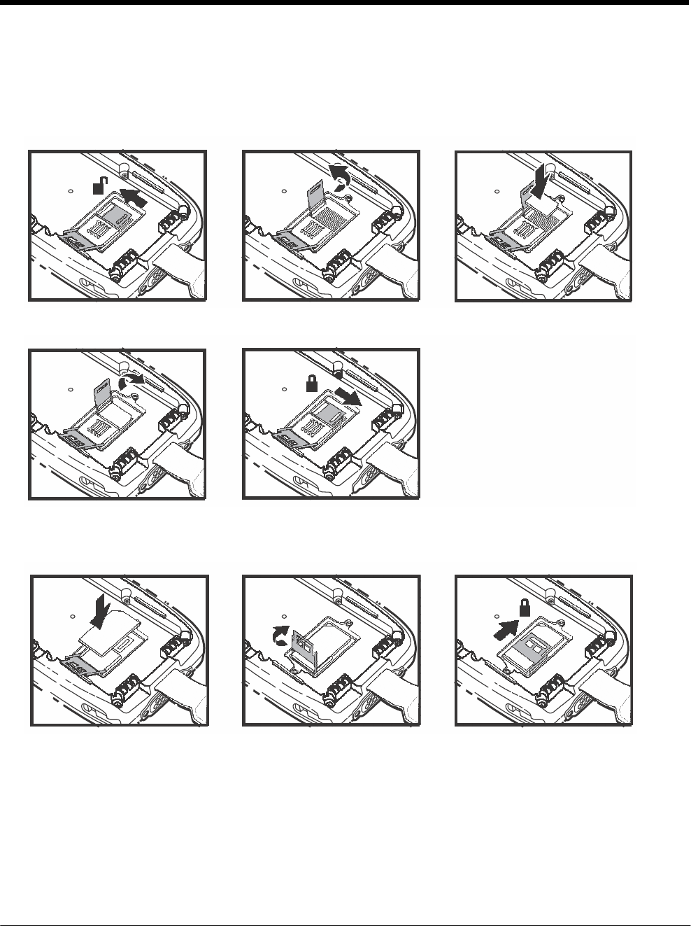
DRAFT COPY 11/11/11
3 - 17
If you are not installing a memory card (i.e., microSD or MicroSDHD card), proceed to step 11.
7. Unlock the memory card latch by sliding the latch toward the top of the terminal.
8. Lift the latch to expose the memory socket.
9. Insert the MicroSD or MicroSDHC card.
7 8 9
10. Close and lock the memory card latch.
10a 10b
11. Insert the SIM card. Align the chamfered corner of the card with the chamfered corner of the socket.
12. Close and lock the SIM card latch.
11 12a 12b

DRAFT COPY 11/11/11
3 - 18
13. Reinstall the shield and screws to protect the sockets.
14. Install and lock the battery. The terminal automatically starts the power up sequence.
Note: The terminal does not power ON unless the battery lock is engaged.

4 - 1
4 DRAFT COPY 11/11/11
Using
the Scan
Image
Engine
Overview
The Dolphin terminal houses a compact image engine that instantly reads popular 1D and 2D bar codes
and supports omni-directional aiming and decoding for greater flexibility in real-world settings. The
image engine can also capture black and white digital images, such as signatures and pictures of dam-
aged inventory.
With the latest CMOS-based technology, the engine works like a digital camera and enables black and
white digital image capture, signature capture, and reading of OCR characters.
Laser Safety
See Laser Safety on page 1-1.
N5603 Beam Divergence Angle
Engines Horizontal Beam Divergence Angle
(degrees)
Vertical Beam Divergence Angle
(degrees)
N5603SR/HD 18.1 14.3
N5603ER 13.1 9.9
LED Safety
See LED Safety on page 1-2.
Image Engine Specifications
Engines 1D 2D Image Capture Aiming Pattern Omni-Directional Aiming
N5603SR/ER/HD
Y Y Y N5603 Red High-Vis
Aiming Pattern (page 4-5)
Y
N5600SR/ER/HD
Y Y Y N5600 Green Aiming
Beam (page 4-5)
Y
Depth of Field
The depth of field measurements used the following parameters:
• Distances are measured from the front of the engine.
• +23°C (+73°F), 0 lux
• Photographic quality codes

DRAFT COPY 11/11/11
4 - 2
Focus N5603/N5600
High Density (HD)
N5603/N5600
Standard Range (SR)
N5603/N5600
Extended Range (ER)
Symbology Distance (in/cm)
Distance (in/cm) Distance (in/cm)
Near Far
Delta
(in/cm) Near Far
Delta
(in/cm)
Near Far
Delta
(in/cm)
3 mil
C39/128 2.0
(5.1) 3.4
(8.6) 1.4
(3.6) - - - - - -
5 mil
C39/128 1.4
(3.6) 4.8
(12.2) 3.4
(8.6) 2.7
(6.9) 6.3
(16.0) 3.6
(9.1) 5.4
(13.7) 9.0
(22.9) 3.6
(9.1)
7.5 mil
C39/128 1.4
(3.6) 5.6
(14.2) 4.2
(10.7) 2.5
(6.4) 9.2
(23.4) 6.7
(17) 4.2
(10.7) 12.6
(32.0) 8.4
(21.3)
10 mil
C39/128 1.4
(3.6) 5.5
(14.0) 4.1
(10.4) 1.6
(4.1) 13.2
(33.5) 11.6
(29.5) 3.1
(7.9) 17.2
(43.7) 14.1
(35.8)
15 mil
C39/128 1.3
(3.3) 7.8
(19.8) 6.5
(16.5) 1.8
(4.6) 19.0
(48.3) 17.2
(43.7) 2.4
(6.1) 20.9
(53.1) 18.5
(47.0)
20 mil
C39/128 2.3
(5.8) 9.2
(23.4) 6.9
(17.5) 2.2
(5.6) 20.1
(51.1) 17.9
(45.5) 2.9
(7.4) 24.0
(61.0) 21.1
(53.6)
100% UPC 1.9
(4.8) 7.1
(18) 5.2
(13.2) 1.8
(4.6) 16.5
(41.9) 14.7
(37.3) 2.7
(6.9) 19
(43.3) 16.3
(41.4)
5 mil
PDF417 1.4
(3.6) 4.8
(12.2) 3.4
(8.6) 2.6
(6.6) 5.2
(13.2) 2.6
(6.6) 6.1
(15.5) 7.4
(18.8) 1.3
(3.3)
6.7 mil
PDF417 1.4
(3.6) 4.8
(12.2) 3.4
(8.6) 2.0
(5.1) 6.5
(16.5) 4.5
(11.4) 4.7
(11.9) 9.8
(24.9) 5.1
(13.0)
10 mil
PDF417 1.7
(4.3) 6.2
(15.7) 4.5
(11.4) 1.5
(3.8) 11.0
(27.9) 9.5
(24.1) 2.4
(6.1) 15.0
(38.1) 12.6
(32.0)
5 mil
MicroPDF 1.8
(4.6) 3.4
(8.6) 1.6
(4.1) - - - - - -
5 mil
Data Matrix 1.9
(4.8) 3.1
(7.9) 1.2
(3.0) - - - - - -
10 mil Data
Matrix/Aztec 1.7
(4.3) 5.3
(13.5) 3.6
(9.1) 2.2
(5.6) 7.9
(20.1) 5.7
(14.5) 5.1
(13.0) 10.5
(26.7) 5.4
(13.7)
20 mil
Data Matrix 2.1
(5.3) 7.8
(19.8) 5.7
(14.5) 2.0
(5.1) 15.3
(38.9) 13.3
(33.8) 3.6
(9.1) 18
(45.7) 14.4
(36.6)
10 mil QR 3.3
(8.4) 5.0
(12.7) 1.7
(4.3) 2.2
(5.6) 7.1
(18.0) 4.9
(12.4) 4.3
(10.9) 10.6
(26.9) 6.5
(16.5)
20 mil QR 2.2
(5.6) 7.9
(20.1) 5.7
(14.5) 2.2
(5.6) 15.5
(39.4) 13.3
(33.8) 2.4
(6.1) 19.6
(49.8) 17.6
(44.7)
32 mil
Maxicode 2.4
(6.1) 8.6
(21.8) 6.2
(15.7) 2.5
(6.4) 17.0
(43.2) 14.5
(36.8) 3.9
(9.9) 23.2
(58.9) 19.5
(49.5)

DRAFT COPY 11/11/11
4 - 3
Supported Bar Code Symbologies
Symbology Type Symbology Name
1D Symbologies Codabar ISBT 128
Codablock F Matrix 2 of 5
Code 3 of 9 MSI Plessey
Code 11
Code 32 Pharmaceutical (PARAF)
Code 93 Straight 2 of 5 IATA
Code 128 Straight 2 of 5 Industrial
EAN with Add-On Telepen
EAN with Extended Coupon Code Trioptic Code
EAN-8 UPC with Add On
EAN-13 UPC-A
GS1-128 UPC-E
GS1 Databar
Interleaved 2 or 5
2D Symbologies Aztec GS1 Databar
Codablock A MaxiCode
Codablock F Micro PDF
PDF417
Data Matrix QR Code
Composite Codes UPC/EAN
UCC/EAN
GS1 Databar
OCR OCR US Money Font
MICR (E 13 B) and SEMI Font
OCR-A
OCR-B
Postal Codes Postnet and most international 4-state codes
Australian Post
British Post
Canadian Post
China Post
Japanese Post
KIX (Netherlands) Post
Korea Post
Planet Code
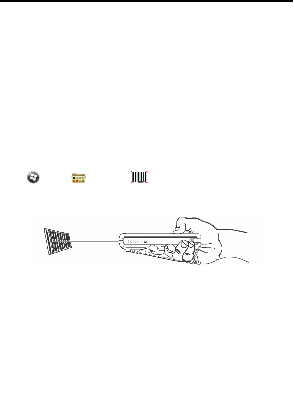
DRAFT COPY 11/11/11
4 - 4
Decoding
The terminal supports two types of image decoding for use in various bar code reading and imaging
applications: full-area imaging and Advanced Linear Decoding (ALD).
Full-Area Imaging
Full-area imaging provides omni-directional reading of linear and non-linear 1D and 2D bar codes, OCR,
signature capture, and picture taking. When reading all bar code types using full-area imaging, a positive
read can be obtained from many positions; see Aiming Beam Options on page 4-5. To achieve the best
read, the aiming beam should be centered horizontally across the bar code.
ALD
ALD provides fast reading of linear and stacked linear bar codes. To achieve a positive read when read-
ing linear 1D and PDF417 bar codes, the aiming beam should be centered horizontally across the bar
code. When ALD is enabled, the reader does not read matrix or postal codes.
To Decode a Bar Code
The aiming beam should be oriented in line with the bar code to achieve optimal decoding. A range
of 4-10 inches (10-25 cm) from the bar code is recommended.
1. Tap > Demos > Scan Demo .
2. Point the Dolphin terminal at the bar code.
3. Press and hold the SCAN key. The aiming beam or pattern appears and the general notification
LED illuminates red.
4. Center the aiming beam over the bar code; see Aiming Beam Options on page 4-5.
Note: For optimum performance, avoid reflections by scanning the bar code at a slight angle.
5. When the bar code is successfully decoded, the general notification LED flashes green and the
terminal beeps.
6. The bar code information is entered into the application in use.
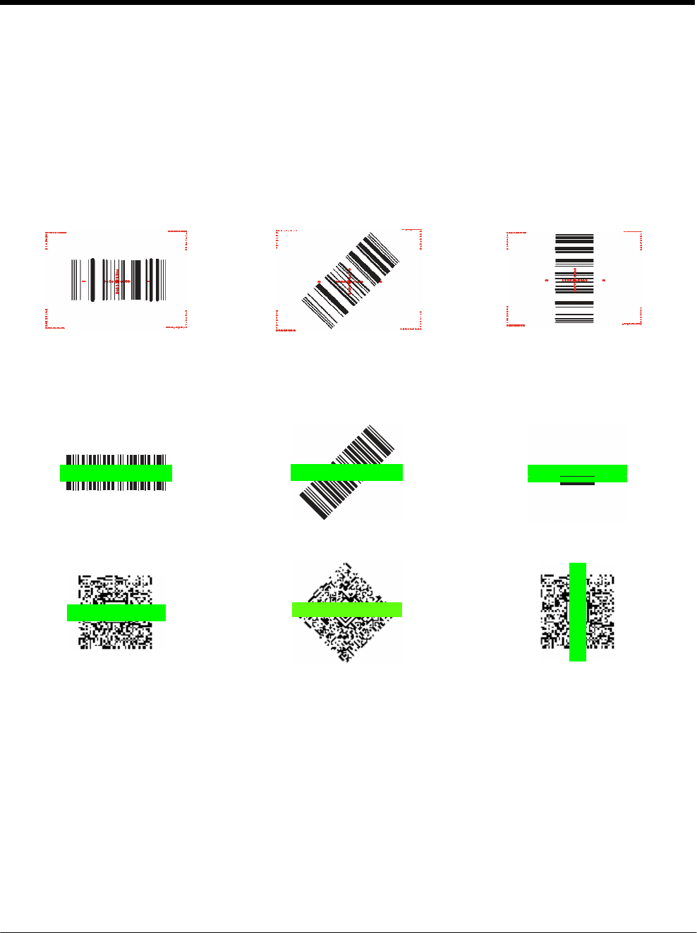
DRAFT COPY 11/11/11
4 - 5
Aiming Beam Options
The aiming beams are smaller when the terminal is held closer to the code and larger when it is farther
from the code. Symbologies with smaller bars or elements (mil size) should be read closer to the unit
whereas symbologies with larger bars or elements (mil size) should be read farther from the unit.
N5603 Red High-Vis Aiming Pattern
If your Dolphin terminal is configured with a N5603 imager, high-vis aimers frame the bar code for more
intuitive aiming. See Laser Safety on page 1-1.
N5600 Green Aiming Beam
Linear Bar Code
2D Matrix Symbol

DRAFT COPY 11/11/11
4 - 6
Capturing Images
The image-capture process is an intuitive, split-second operation for experienced users. By following the
basic guidelines, new users can easily develop their own technique and, with practice, quickly learn to
adapt it to different application environments.
Image Preview
When the imaging process is initiated, the touch screen displays a preview of the object. This is a live
video image of what the imager is currently viewing. The live video image has a slightly degraded
appearance compared to the captured image. This is normal.
Scan Key
On all 7800 terminals, the SCAN key captures images.
File Formats
File formats supported for image storage include Bitmap (BMP), JPEG (JPG) and Portable Network
Graphics (PNG). The default file format for images is a grayscale JPG.
Compression
Digital images have a maximum image size of 640 x 480 pixels and may have up to a 256 grayscale
image definition.
The image quality and related file size are determined by the data compression method used by the soft-
ware application used to take images. The average size of the image file is approximately 4–8K. How-
ever, the size of the image depends on the content of the image - the more complex the content, the
larger the file size.
Taking an Image
The following steps are basic guidelines for taking images:
1. Tap > Demos > Imaging Demo .
2. Point the Dolphin terminal at the object.
3. To preview the image, press and hold the SCAN key. The general notification LED illuminates red.
4. Adjust the terminal’s position until the object appears on the touch screen the way you want it to
appear in the image.
5. Hold the terminal still and release the SCAN key. The LED flashes green, the screen briefly flashes,
and then the captured image appears on the screen.
6. Tap file Save or Save As.
Note: Unless otherwise specified by the application in use, the image is saved to the \My
Device\My
Documents folder.
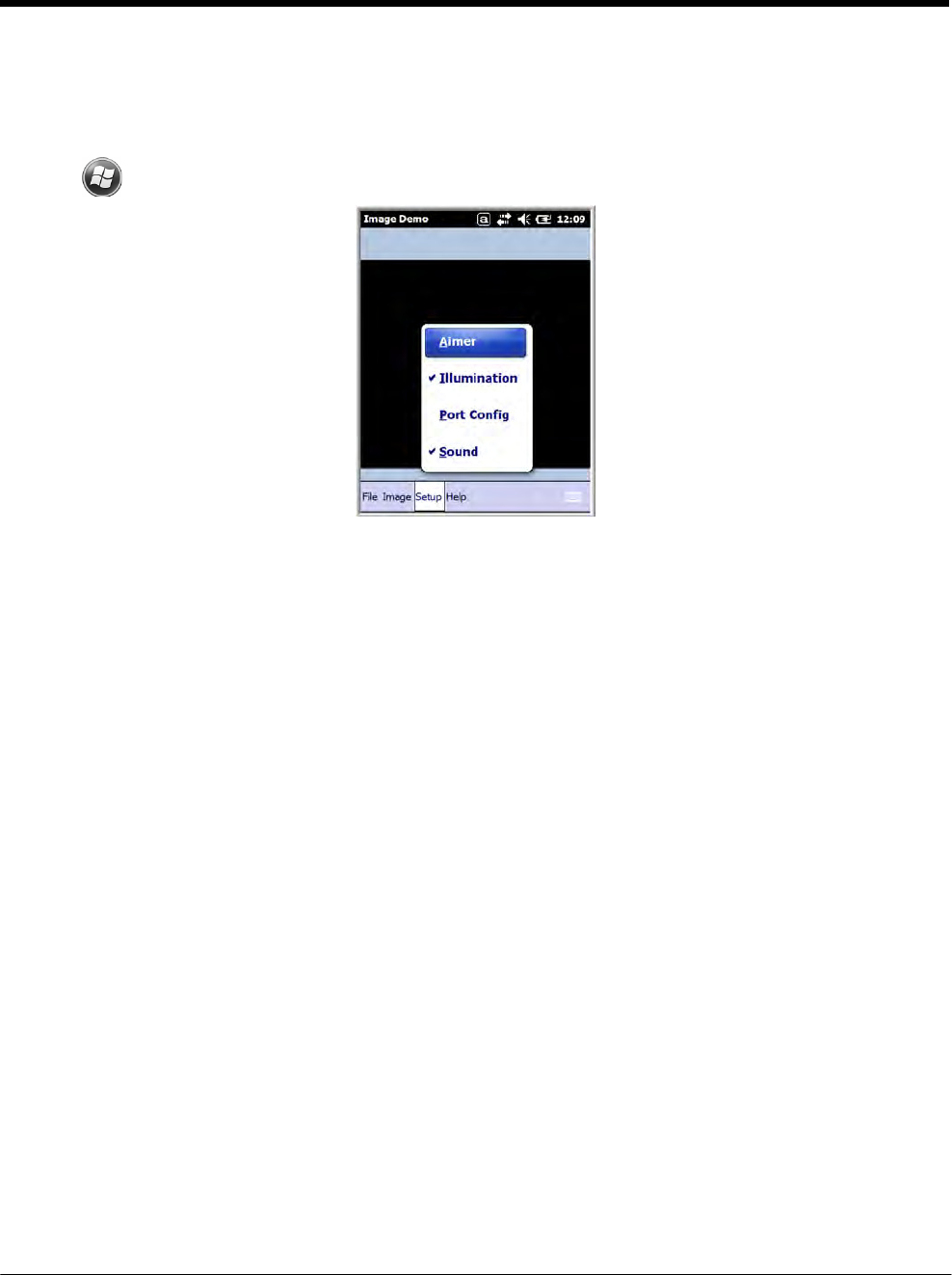
DRAFT COPY 11/11/11
4 - 7
Enabling the Aimer
You can enable the aiming pattern for imaging in the Imaging Demo. For details about the aimer, see
Aiming Beam Options on page 4-5.
1. Tap > Demos > Imaging Demo > Setup menu > Aimer.
2. The aiming pattern is now enabled for imaging.
Uploading Images
Image files can be uploaded to a host workstation using Microsoft ActiveSync or Windows Mobile Device
Center and a Dolphin communication peripheral. For additional information see Connecting and
Synchronizing the Terminal and Workstation on page 8-6.

DRAFT COPY 11/11/11
4 - 8
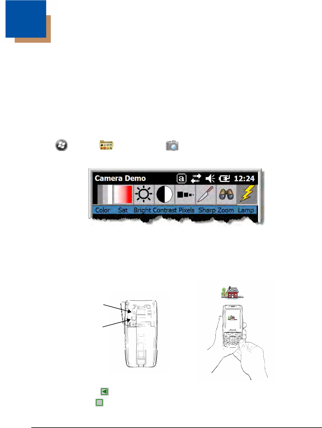
5 - 1
5 DRAFT COPY 11/11/11
Using
the
Color
Camera
Overview
Dolphin 7800 terminals equipped with a 3.0-Megapixels Resolution color camera with Automated Cam-
era Control (ACC), and an Application Programming Interface (API) provide easy integration of color pic-
ture and video capture into business applications. The camera lens and camera flash are located on the
back panel of the terminal.
Taking a picture using the Camera Demo tool
1. Tap > Demos > Camera Demo .
2. Adjust the camera settings using the icon menu at the top of the display screen.
3. Point the terminal's camera lens at the object you want to capture. The camera lens is located on the
back panel of the terminal.
4. Center the object in the touch screen display.
5. Press the ENT key or tap Snap on the touch screen. The general notification LED illuminates red
during picture capture.
Flashlight/
Camera Flash
Camera Lens
Note: Tap the green arrow to review or edit your pictures.
Tap the green box to exit the picture review/edit screen.
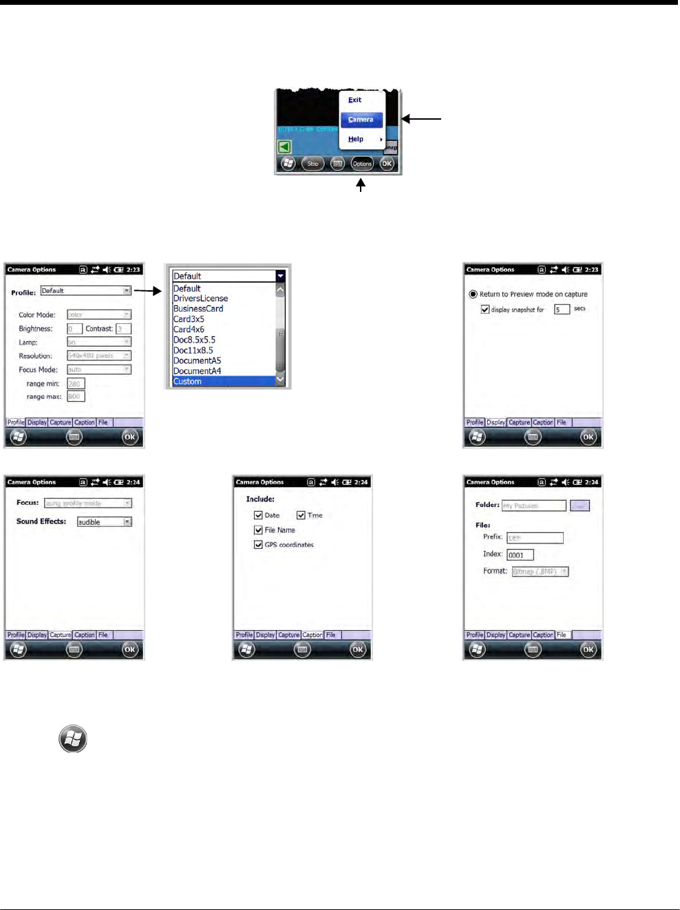
DRAFT COPY 11/11/11
5 - 2
Options
Tap Options > Camera.
The Camera Options menu appears. There are five tabs of configurable options accessible from the
Camera Options menu.
Profile Tab Display Tab
The profile tab allows you to customize your
camera settings, or chose from several
predefined profiles designed to provide the
best picture quality for common tasks.
Capture Tab Caption Tab File Tab
Taking a picture using the Windows Embedded Handheld 6.5 Camera tool
1. Tap > Pictures & Videos > Camera
2. Point the terminal's camera lens at the object you want to capture. The camera lens is located on the
back panel of the terminal.
3. Center the object in the touch screen display.
4. Press the ENT key.
5. The touch screen displays the captured photo.
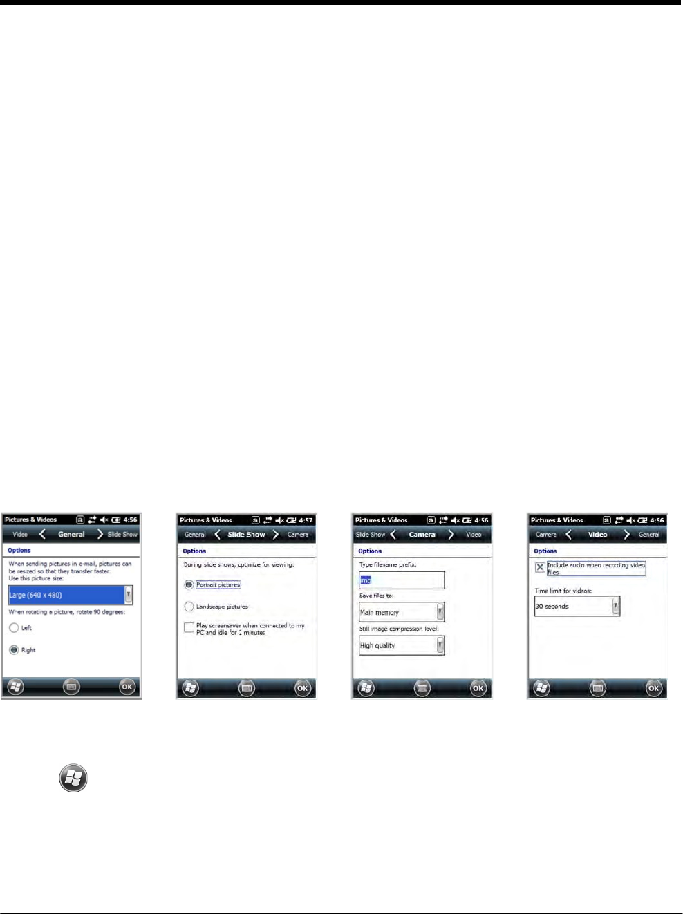
DRAFT COPY 11/11/11
5 - 3
6. Tap OK on the Tile Bar to return to the active viewfinder screen.
Menu
Tap Menu on the Tile Bar at the bottom of the touch screen to adjust the camera settings, switch to video
mode, and access additional camera options.
Item Descriptions
Video Activate Video Mode
Mode Set Mode (i.e., Normal, Burst, or Timer)
Resolution Set Picture Resolution (i.e., QVGA, VGA, SVGA, XGA, UXGA, or QXGA)
Zoom Set Zoom (i.e., x1, x2, or x3)
Flash Set Camera Flash On or Camera Flash Off
Focus Set Focus Off, Focus On, Focus on Trigger, or Fixed-Focus
Brightness Set the brightness setting from +2.0 EV to -2.0 EV in .5 EV increments
Full Screen Switch to full screen mode
Options Set Camera Options, Video Options, Slide Show Options or General Options
Options
Tap Menu > Options. The Options menu contains four screens:
General Tab Slide Show Tab Camera Tab Video Tab
Recording Video
1. Tap > Pictures & Videos > Camera > Menu > Video
2. Point the terminal's camera lens at the object you want to capture.
3. Press the ENT key to start recording.
4. Tap Stop on the touch screen or press ENT to stop recording.

DRAFT COPY 11/11/11
5 - 4
Uploading Pictures and Videos
Piture and Video files can be uploaded to a host workstation using Microsoft ActiveSync or Windows
Mobile Device Center and a Dolphin communication peripheral. For additional information see
Connecting and Synchronizing the Terminal and Workstation on page 8-6.
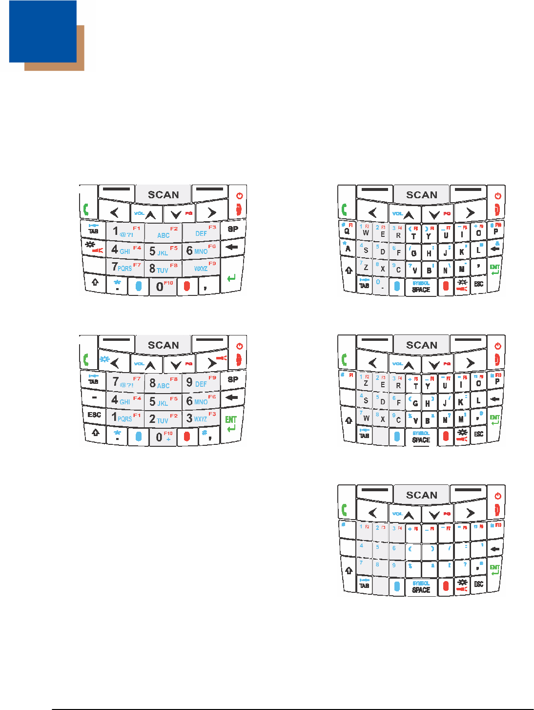
6 - 1
6 DRAFT COPY 11/11/11
Using
the Keyboards
Available Keyboards
Note: Contact a sales representative for information on additional keyboard options.
30-Key Numeric Keyboard 46-Key QWERTY Keyboard
ESC
ENT
30-Key Numeric (Calculator) Keyboard 46-Key AZERTY Keyboard
A
Q
0
.
46-Key QWERTZ
Keyboard
Q
W
E
R
T Z
U
I
O
P
A
S
D
F
G H
J
K
L
Y
X
C
0
.
V B
N
M
All Keyboards Contain the Following:
• Backlit for easy viewing in various lighting conditions.
• Centrally located Scan key for both right- and left-hand operation.
• Color-coding so you can clearly see the most common keyboard combinations.
• Function, navigation, and modifier keys.
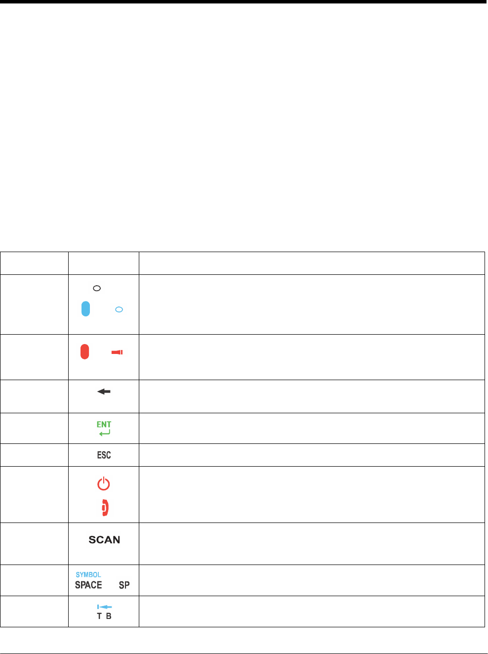
DRAFT COPY 11/11/11
6 - 2
Keyboard Combinations
See 30-Key Numeric Keyboard on page 6-4.
See 30-Key Numeric (Calculator) Keyboard on page 6-6.
See 46-Key QWERTY Keyboard on page 6-8.
See 46-Key AZERTY Keyboard on page 6-11.
See 46-Key QWERTZ Keyboard on page 6-14.
Common Buttons
See Using the Function Keys on page 6-2.
See Using the Modifier Keys on page 6-3.
See Using the Navigation Keys on page 6-3.
Using the Function Keys
Name Key Symbol Function
Backlight
or
&
Blue
Turns the keyboard backlight on or off.
Note: On terminals with the 30-Key Numeric (Calculator) Keyboard the
backlight feature requires the blue modifier key.
Flashlight
&
Red
Turns the flashlight on or off. The flashlight is located on the back panel of the
terminal.
Backspace
Moves the cursor back one space each time the key is pressed. If you are
typing text, it deletes the previous character each time it is pressed.
Enter
Confirms data entry.
Escape
Cancels the current action.
Power/End
Call Key
The Power key, located in the upper right corner of the keypad, puts the
terminal in Suspend Mode or wakes the terminal from Suspend Mode, see
Suspend Mode on page 2-11. This key is also used to end/diconnect a phone
calls.
SCAN Key Activates the scan and wakes the terminal from Suspend Mode.
The key location allows convenient one-handed image-taking and/or bar code
decoding.
Space
or
Moves the cursor one space.
Tab Moves the cursor to the next tab stop or the next control (on a form).
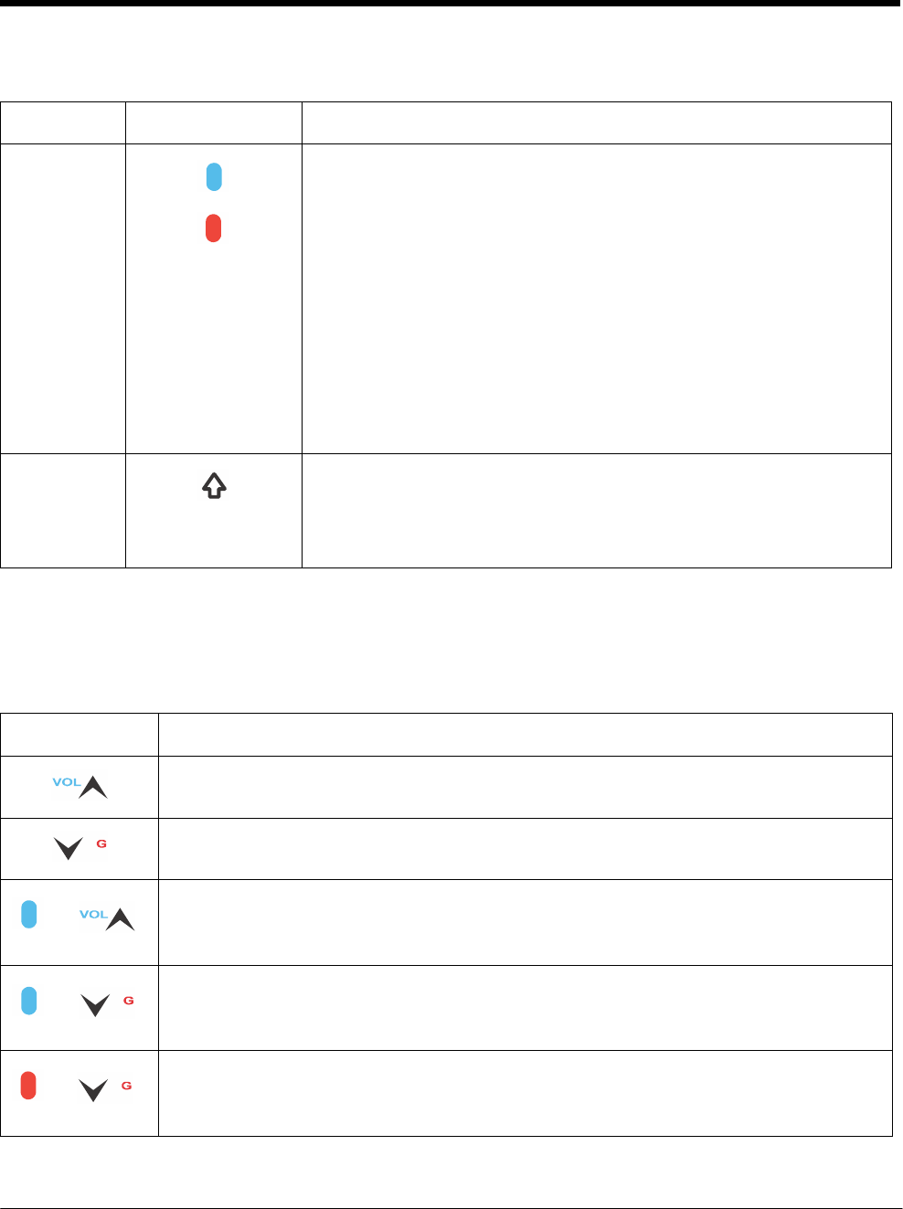
DRAFT COPY 11/11/11
6 - 3
Using the Modifier Keys
Name Key Function
Blue & Red
Blue
Red
The blue and red keys are used in combination with other keys to type
special characters and perform system functions. Each keyboard is
color-coded to indicate the character typed or function performed when
specific keys are pressed immediately after the blue or red modifier key.
Normal
Press the blue or red key once to modify only the next key pressed.
Locked
Press the blue or red key twice to toggle the modifier lock on or off.
If a modifier key is locked on, the next keys pressed are modified until the
lock is turned off. This prevents having to press the modifier key each
time a key is pressed.
Note: Press the locked modifier key once to temporarily unlock the
modifier key for a single key stroke.
Shift
The shift key modifies only the next key pressed; it must be pressed
before each key you wish to modify. Shift toggles the keyboard between
uppercase alphabet mode and lowercase alphabet mode.
Press the shift key twice to toggle Caps Lock ON or OFF.
Using the Navigation Keys
Located in the center of each keyboard for easy access with either hand, the navigation keys navigate
the cursor through application screens.
Key
Function
Moves the cursor up one row or line.
Moves the cursor down one row or line.
&
Blue
Raises the volume.
&
Blue
Lowers the volume.
&
Red
Moves the cursor down one page.
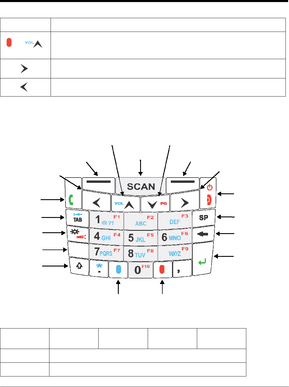
DRAFT COPY 11/11/11
6 - 4
Key Function
&
Red
Moves the cursor up one page.
Moves the cursor one character to the right.
Moves the cursor one character to the left.
Note: Additional functionality varies according to the application in use.
30-Key Numeric Keyboard
Up Navigation Key, Volume Up, Page Up Down Navigation Key, Volume Down, Page Down
Left Soft
Key
Left Navigation Key
SCAN Key Right Soft Key
Right Navigation Key
SEND key
Tab Key
Backlight /
Flashlight Key
Power Key / END
Key
Space
Key
Backspace
Key
Escape
Key
Shift
Key
ESC
ENT
Enter Key
Blue
Key
Red Key
30-Key Numeric Keyboard Combinations
Key
Normal
Blue + Normal
Blue + Normal
+ Shift
Red + Normal
Left Soft Key Left Soft Key performs the left function.
SCAN SCAN

DRAFT COPY 11/11/11
6 - 5
Key Normal Blue + Normal Blue + Normal
+ Shift
Red + Normal
Right Soft Key Right Soft Key performs right function.
SEND SEND Cold Boot Cold Boot SEND
Left Navigation
Left
Up Navigation Volume Up Volume Up Volume Up Page Up
Down
Navigation
Volume Down Volume Down Volume Down Page Down
Right
Navigation
Right
Power/END Power On/Off or
END Call Warm Boot Warm Boot Power On/Off or
END Call
TAB TAB back TAB TAB TAB
1 1 @ ? ! @ or ? or ! F1
2 2 abc ABC F2
3 3 def DEF F3
Space Space
Backlight Backlight Backlight Backlight flashlight
4 4 ghi GHI F4
5 5 jkl JKL F5
6 6 mno MNO F6
Backspace backspace
ESC Escape
7 7 pqrs PQRS F7
8 8 tuv TUV F8
9 9 wxyz WXYZ F9
ENTER Enter
Shift Shift
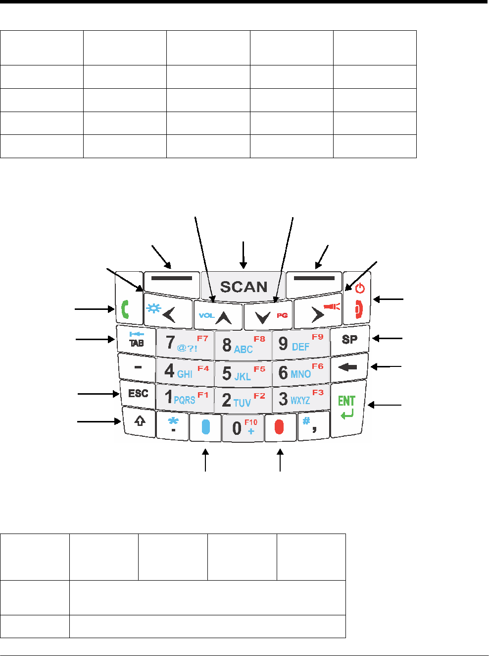
DRAFT COPY 11/11/11
6 - 6
Key Normal Blue + Normal Blue + Normal
+ Shift
Red + Normal
Period period asterisk asterisk period
Blue Blue
0 0 0 0 F10
Red Red
30-Key Numeric (Calculator) Keyboard
Up Navigation Key, Volume Up, Page Up Down Navigation Key, Volume Down, Page Down
Left Soft
Key
Left Navigation key,
Backlight
SCAN key Right Soft Key
Right Navigation key,
Flashlight
Send key Power key, End Key
Tab key Space key
Backspace,
Delete key
Escape
key
Shift
key
Enter key
Blue
key
Red key
30-Key Numeric (Calculator) Keyboard Combinations
Key Normal Blue +
Normal
Blue +
Normal +
Shift
Red +
Normal
Left Soft
Key
Left Soft Key
SCAN SCAN

DRAFT COPY 11/11/11
6 - 7
Key Normal Blue +
Normal
Blue +
Normal +
Shift
Red +
Normal
Right Soft
Key
Right Soft Key
SEND
SEND
Cold Boot
Cold Boot
SEND
Left Left Backlight Left Left
Up Volume Up Volume Up Volume Up Page Up
Down Volume
Down
Volume
Down
Volume
Down Page Down
Right Right Right Right Flashlight
POWER\EN
D
Power\End Warm Boot Warm Boot Power\End
TAB TAB back TAB TAB TAB
7 7 @ or ? or ! @ or ? or ! F7
8 8 abc ABC F8
9 9 def DEF F9
Space Space
Dash/Minus - - - -
4 4 ghi GHI F4
5 5 jkl JKL F5
6 6 mno MNO F6
Backspace backspace
ESC Escape
1 1 pqrs PQRS F1
2 2 tuv TUV F2
3 3 wxyz WXYZ F3
ENTER Enter
Shift Shift
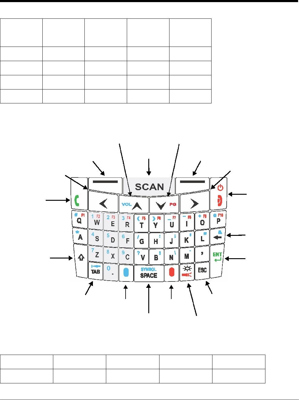
DRAFT COPY 11/11/11
6 - 8
Key Normal Blue +
Normal
Blue +
Normal +
Shift
Red +
Normal
Period period asterisk asterisk period
Blue Blue
0 0 plus + 0 F10
Red Red
46-Key QWERTY Keyboard
Up Navigation Key, Volume Up, Page Up Down Navigation Key, Volume Down, Page Down
Left Soft
Key
Left Navigation key
SCAN key Right Soft Key
Right Navigation key
Send key Power key, End Key
Backspace,
Delete key
Shift key Enter key
Tab key Escape key
Blue
key
Red key
Space\Symbol
key
Backlight\Flashlight key
46-Key QWERTY Keyboard Combinations
Key Normal Shift + Normal Blue + Normal Red + Normal
Send Send Send Cold Boot Send

DRAFT COPY 11/11/11
6 - 9
Key Normal Shift + Normal Blue + Normal Red + Normal
Left Soft Key Left Soft Key
SCAN Scan
Right Soft Key Right Soft Key
Power/End Power/End Power/End Warm Boot Power/End
Left Navigation
Key
Left
Up Navigation Up Up Volume Up Page Up
Down
Navigation
Down Down Volume Down Page Down
Right
Navigation
Right
Q q Q # (pound/group) F1
W w W 1 F2
E e E 2 F3
R r R 3 F4
T t T ( F5
Y y Y ) F6
U u U _ (underscore) F7
I i I - (minus) F8
O o O + (plus) F9
P p P @ F10
A a A * (asterisk)
S s S 4
D d D 5
F f F 6
G g G /

DRAFT COPY 11/11/11
6 - 10
Key Normal Shift + Normal Blue + Normal Red + Normal
H h H : (colon)
J j J ; (semi-colon)
K k K ‘ (single quote)
L l L “ (double quote)
Backspace Backspace Backspace & (ampersand)
Shift Shift
Z z Z 7
X x X 8
C c C 9
V v V ? (question mark)
B b B
!
(exclamation
point)
N n N \ (back slash)
M m M . (period)
Comma , (comma) < , (comma) , (comma)
ENT Enter
TAB Tab Back Tab Back Tab Tab
Period . (period) > 0 . (period)
Blue Blue
SYMBOL/
SPACE
Space Space SYMBOL Space
Red Red
Backlight Backlight Backlight Backlight Flashlight
ESC Escape
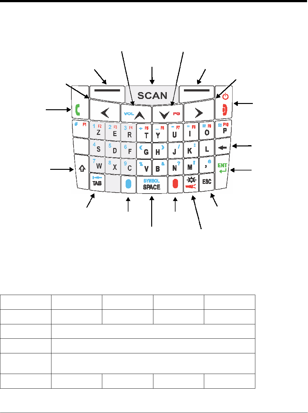
DRAFT COPY 11/11/11
6 - 11
Q
46-Key AZERTY Keyboard
Up Navigation Key, Volume Up, Page Up Down Navigation Key, Volume Down, Page Down
Left Soft
Key
Left Navigation key
SCAN key Right Soft Key
Right Navigation key
Send key Power key, End Key
A
Backspace,
Delete key
Shift key
0
.
Enter key
Tab key Escape key
Blue
key
Red key
Space\Symbol
key
Backlight\Flashlight key
46-Key AZERTY Keyboard Combinations
Key Normal Shift + Normal Blue + Normal Red + Normal
Send Send Send Cold Boot Send
Left Soft Key Left Soft Key
SCAN Scan
Right Soft Key Right Soft Key
Power/End Power/End Power/End Warm Boot Power/End

DRAFT COPY 11/11/11
6 - 12
Key Normal Shift + Normal Blue + Normal Red + Normal
Left Navigation
Key
Left
Up Navigation
Up
Up
Volume Up
Page Up
Down
Navigation
Down Down Volume Down Page Down
Right
Navigation
Right
A
a
A
# (number sign)
F1
Z z Z 1 F2
E e E 2 F3
R r R 3 F4
T t T + (plus) F5
Y y Y _ (underscore) F6
U u U - (minus) F7
I i I = (equal) F8
O o O " (double quote)
F9
P p P áü F10
Q q Q * (asterik)
S s S 4
D d D 5
F f F 6
G g G (
H h H )
J j J / (forward slash)
K k K : (colon)
L l L

DRAFT COPY 11/11/11
6 - 13
Key Normal Shift + Normal Blue + Normal Red + Normal
Backspace Backspace Backspace
Shift Shift
W w W 7
X x X 8
C c C 9
V v V % (percent)
B b B & (ampersand)
N n N
? (question
mark)
M m M
! (exclamation
mark)
Comma , (comma) < @ , (comma)
ENT Enter
TAB Tab Back Tab Back Tab Tab
Period . (period) > 0 . (period)
Blue Blue
SYMBOL/
SPACE
Space Space SYMBOL Space
Red Red
Backlight Backlight Backlight Backlight Flashlight
ESC Escape
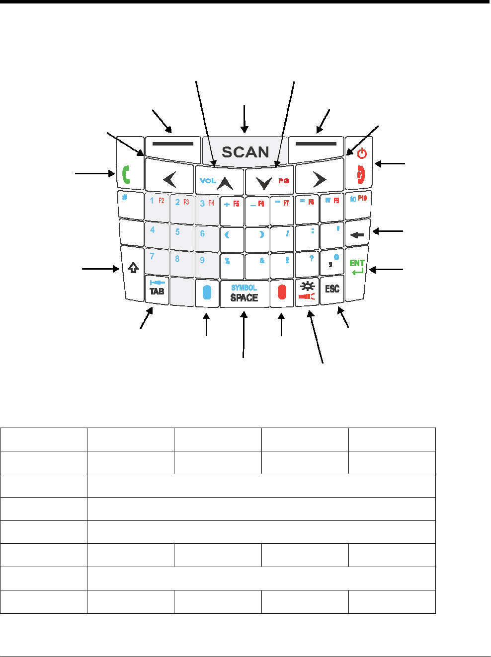
DRAFT COPY 11/11/11
6 - 14
46-Key QWERTZ Keyboard
Up Navigation Key, Volume Up, Page Up Down Navigation Key, Volume Down, Page Down
Left Soft
Key
Left Navigation key
SCAN key Right Soft Key
Right Navigation key
Send key Power key, End Key
Q
W
E
R
T
Z
U
I
O
P
A
S
D
F
G
H
J
K
L
Backspace,
Delete key
Shift key
Y
X
C
0
.
V
B
N
M
Enter key
Tab key Escape key
Blue
key
Red key
Space\Symbol
key
Backlight\Flashlight key
46-Key QWERTZ Keyboard Combinations
Key Normal Shift + Normal Blue + Normal Red + Normal
Send Send Send Cold Boot Send
Left Soft Key Left Soft Key
SCAN Scan
Right Soft Key Right Soft Key
Power/End Power/End Power/End Warm Boot Power/End
Left Navigation Left
Up Navigation Up Up Volume Up Page Up

DRAFT COPY 11/11/11
6 - 15
Key Normal Shift + Normal Blue + Normal Red + Normal
Down
Navigation
Down Down Volume Down Page Down
Right
Navigation
Right
Q
q
Q
# (number sign)
F1
W w W 1 F2
E e E 2 F3
R r R 3 F4
T t T + (plus) F5
Y y Y _ (underscore) F6
U u U - (minus) F7
I i I = (equal) F8
O o O “ (double quote) F9
P p P
á
U
F10
A a A * (asterisk)
S s S 4
D d D 5
F f F 6
G g G (
H h H )
J j J / (forward slash)
K k K : (colon)
L l L ‘ (single quote)
Backspace Backspace Backspace
Shift Shift
Y y Y 7

DRAFT COPY 11/11/11
6 - 16
Key Normal Shift + Normal Blue + Normal Red + Normal
X x X 8
C c C 9
V v V % (percent)
B b B & (ampersand)
N n N
! (exclamation
mark)
M m M ? (question mark)
Comma , (comma) < @ , (comma)
ENT Enter
TAB Tab Back Tab Back Tab Tab
Period . (period) > 0 . (period)
Blue Blue
SYMBOL/
SPACE
Space Space SYMBOL Space
Red Red
Backlight/
Flashlight
Backlight Backlight Backlight Flashlight
ESC Escape
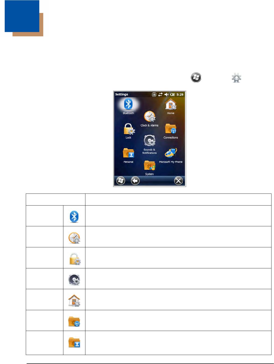
7 - 1
7 DRAFT COPY 11/11/11
System
Settings
Overview
Customized settings are available on the System Settings menu. Tap > Settings and the set-
tings screen opens.
Icon Description
Bluetooth Configures the Bluetooth radio. See Working with the Bluetooth Radio on page 10-
1.
Clock &
Alarms
Set the system clock, date, time and schedule alarms. See Clock & Alarms on page
7-2.
Lock Password protect the terminal to limit access to the terminal.
Sounds &
Notifications
Set the sound volume, enable or disable sounds for specific actions, set sound
parameters for system notifications and enable or disable vibrator notification.
Home Customize the look and the information displayed on the Home screen.
Connections Establishes network connections settings. See Connections Menu on page 8-1.
Personal Customizes buttons, and set SIP options. See Personal Menu on page 7-3.
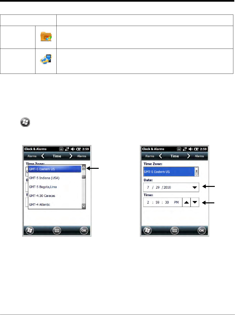
DRAFT COPY 11/11/11
7 - 2
Icon
Description
System Adjusts system settings. See System Menu on page 7-7.
Microsoft My
Phone
This icon is present on Dolphin models equipped with WWAN radio (GSM/UMTS/
GPRS/EDGE) capabilities. Microsoft My Phone synchronizes your phone’s contacts,
calendar, tasks, text messages, music, photos, videos, and other documents with
your My Phone account at http://myphone.microsoft.com.
Clock & Alarms
The Clock & Alarms settings can be accessed from the Home screen or the Settings Menu.
1. On the Home screen, tap the line that displays the time and date
OR
Tap > Settings > Clock & Alarms,
2. The Clock Settings screen appears. This setting sets the system clock. All scheduled items run
according to this setting.
Tap the arrow to the right of the time zone to open the drop down menu. Select the appropiate time
zone from the menu. Set the correct time and date in the remaining fields and tap OK to save.
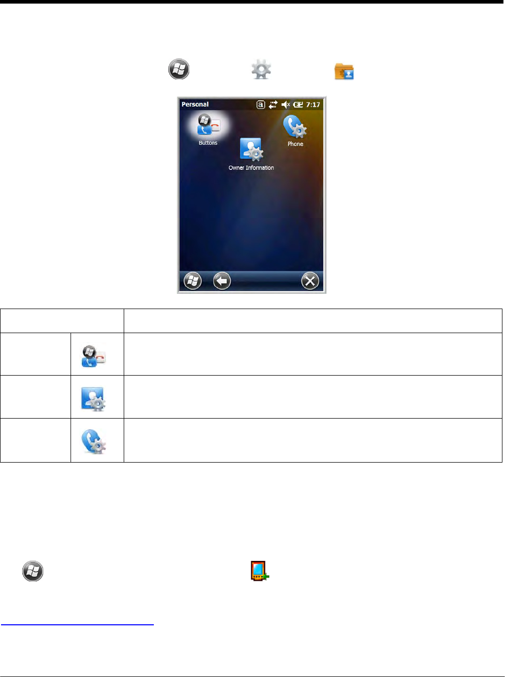
DRAFT COPY 11/11/11
7 - 3
Personal Menu
To access the Personal Menu, tap > Settings > Personal . The screen opens displaying
the Personal Menu.
Icon Description
Buttons Program the side buttons to perform specific tasks. See Buttons on page 7-3.
Owner
Information
Enter your contact information (e.g., name, company, address, telephone number
and E-mail address).
Phone
This Phone icon is present on Dolphin models equipped with WWAN radio (GSM/
UMTS/GPRS/EDGE) capabilities. Tap this icon to set up user parameters. See
Setup Options on page 9-5.
Buttons
The Buttons setting programs certain keyboard buttons to launch applications or execute commands.
Enable HotKeys
Default Buttons setting assignments are inactive until you enable the HotKeys Power Tool.
Tap > Power Tools and tap the HotKeys icon once. HotKeys is enabled, and the button
assignments in the Buttons setting are active.
For more information about the HotKeys Power Tool, refer to the Dolphin Power Tools User’s Guide,
http://www.honeywellaidc.com/ is available for download from the web at www.honeywellaidc.com.
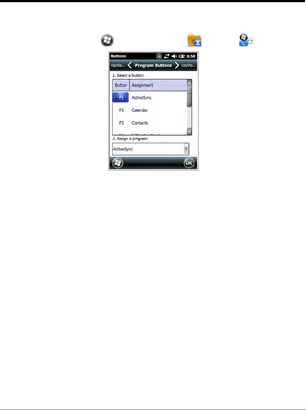
DRAFT COPY 11/11/11
7 - 4
Changing Button Assignments
1. After HotKeys is enabled, tap > Settings > Personal > Buttons .
Note: The buttons that appear on this window are the only buttons that can be programmed via the Buttons setting.
You cannot add buttons to this
window.
2. To change button assignment, tap on the name of the button in the Button column, and then select
a program or command in the Assign a program drop down list.
3. Tap OK to save.
4. Press the button to verify that the program is launched or action performed.
Available Applications
The Assign a program list contains the applications installed on the terminal. If there is a program
installed that you would like to see in this list, paste a Shortcut to the program in the \\Windows\Start
Menu\Programs folder. For instructions about creating shortcuts, see Using File Explorer on page 7-5.
Additional Functions
The Assign a program list also contains the following commands:
Command Description
<Context Menu> Performs the same function as tap-and-hold to open the context menu for the control.
<Home> Returns to the Home screen.
<Input Panel> Opens the soft input panel.
<Left Softkey> Opens the menu or performs the action displayed on the left side of the Command bar.
<None> Nothing happens when the button is pressed.
<OK/Close> Performs the same function as tapping OK on the screen.
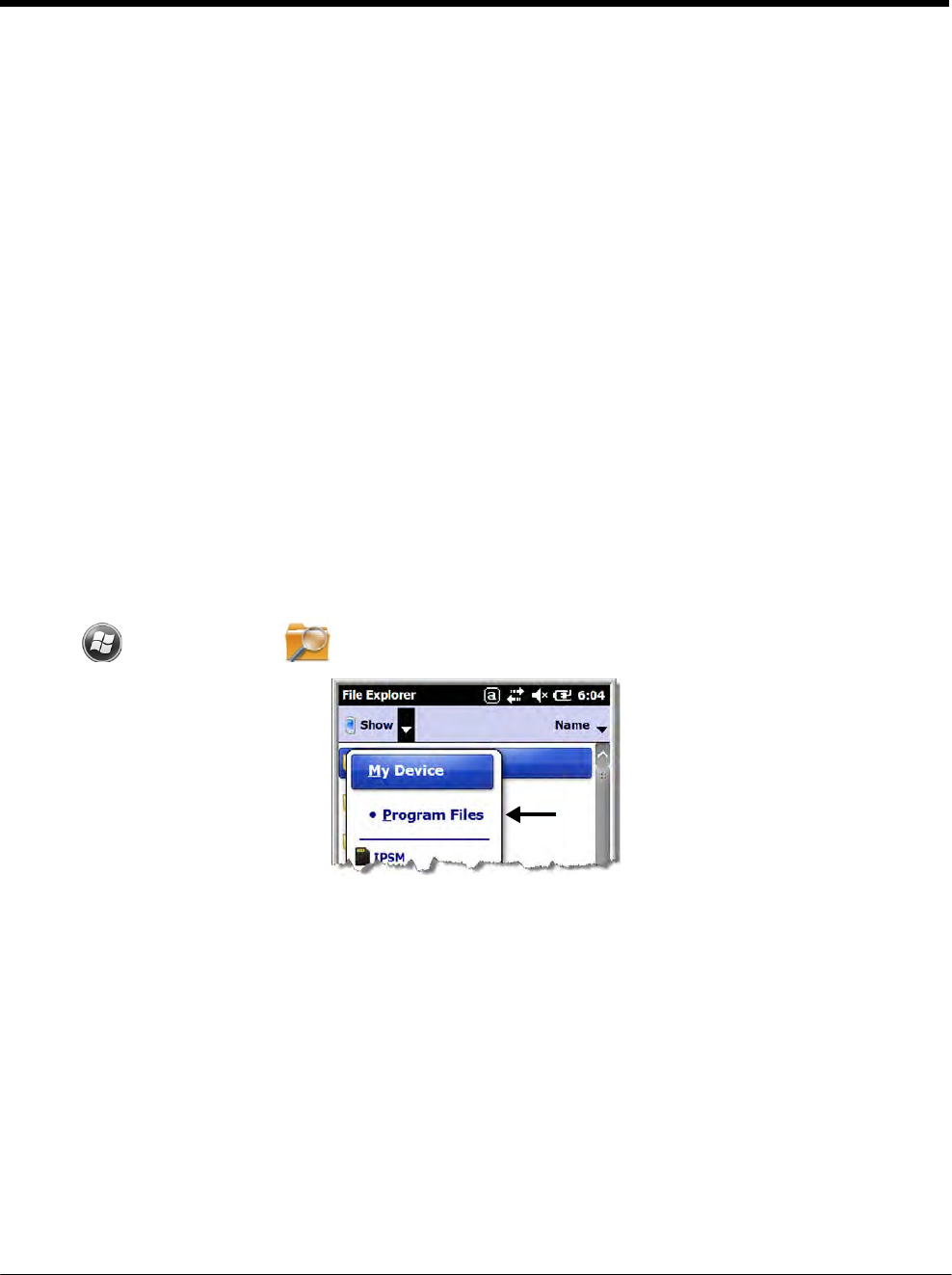
DRAFT COPY 11/11/11
7 - 5
Command Description
<Right Softkey> Opens the menu or performs the action displayed on the right side of the Command bar.
<Rotate Screen> Changes the screen orientation from portrait to landscape.
<Scan1> Activates the scanner/imager.
<Scan2> Activates the scanner/imager.
<Scroll Down> Scrolls down in the open application.
<Scroll Left> Scrolls left in the open application.
<Scroll Right> Scrolls right in the open application.
<Scroll Up> Scrolls up in the open application.
<Start Menu> Opens the Start menu.
Using File Explorer
If you do not see the program listed, you can either use File Explorer to move the program or ActiveSync
on the workstation to create a shortcut to the program and place the shortcut in the Start Menu folder.
Note: We recommend that you Copy and Paste Shortcut so that you do not alter your program configurations by
accident. Using Copy and Paste Shortcut (as opposed to Cut and Paste) ensures that the program files
remain where they need to be for the system to find them to perform system functions.
1. Tap > File Explorer , and navigate to the program (My Device > Program Files).
2. Tap and hold on the program, then tap Copy on the pop-up menu.
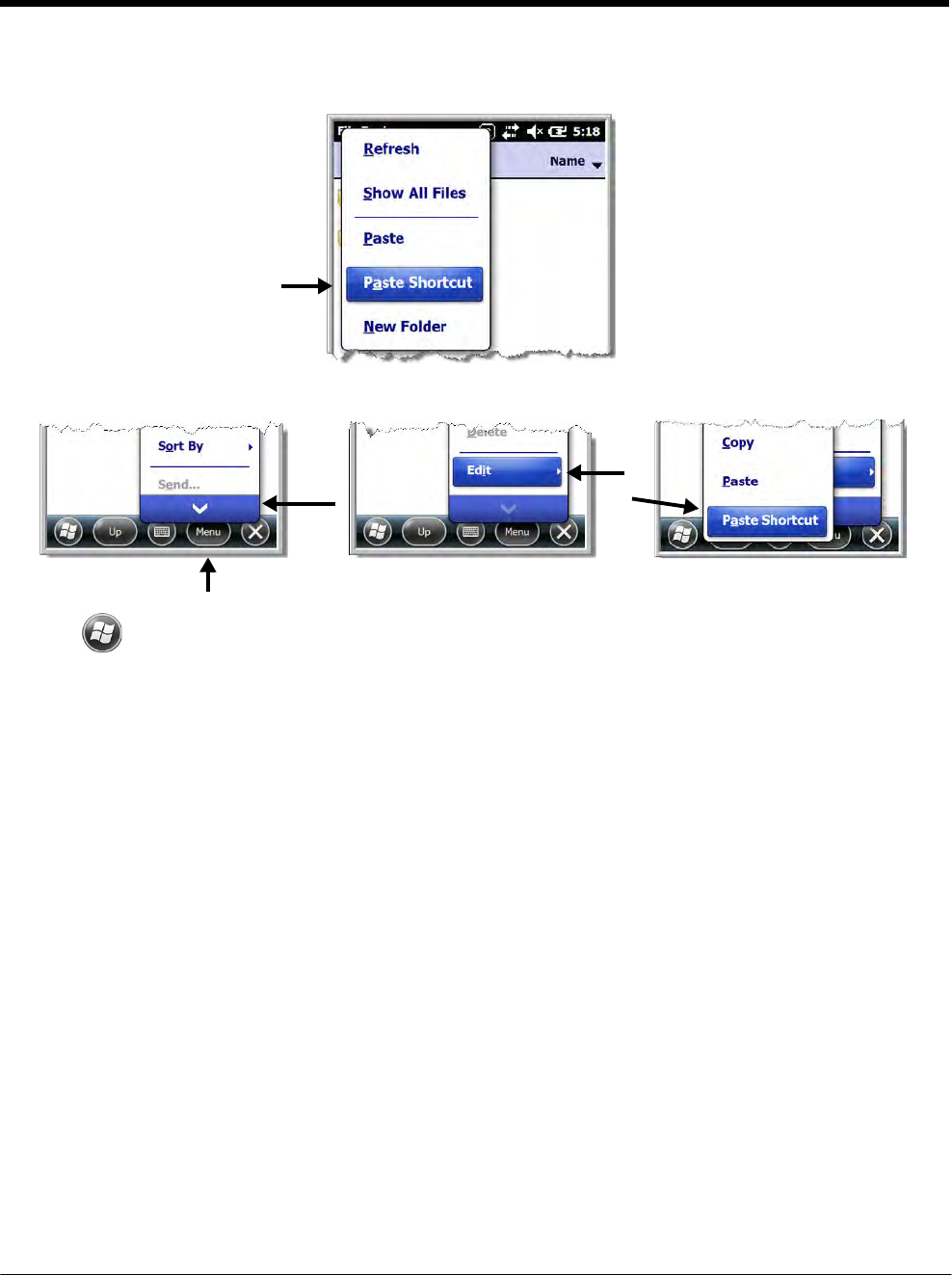
DRAFT COPY 11/11/11
7 - 6
3. Navigate to the Windows folder and open the Start Menu (My Device > Windows > Start Menu >
Programs), tap and hold a blank area of the window, and tap Paste Shortcut on the pop-up menu.
Note: If there is no blank space available in the window, tap on Menu > Edit > Paste Shortcut.
4. Tap to verify that the program now appears on the Start menu.
Using ActiveSync on the Workstation
Here, you are performing the same basic process as on the terminal, except that you are using the
Explore utility (Windows Explorer) to copy and paste the shortcut.
1. Open ActiveSync > Explore and navigate to the program.
2. Right-click on the program and select Create Shortcut.
3. Select the shortcut, right-click, and select Cut.
4. Navigate to the Start Menu folder (Windows > Start Menu > Programs).
5. Right-click on an empty area and select Paste Shortcut.
6. On the terminal, tap the Start menu.
7. Verify that program appears.
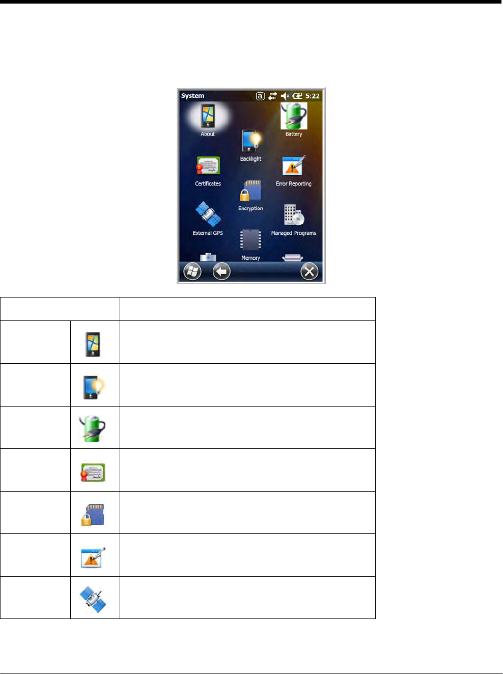
DRAFT COPY 11/11/11
7 - 7
System Menu
The System menu enables you to verify and sometimes alter system parameters. To access the System
menu, go to Start > Settings > System. Tap the appropriate icon to open that system setting.
Icon See Page
About See About on page 7-8.
Backlight See Backlight on page 7-9.
Battery See Battery on page 7-10.
Certificates See Certificates on page 7-10.
Encryption See Encryption on page 7-11.
Error
Reporting
See Error Reporting on page 7-11.
External
GPS
See External GPS on page 7-11.
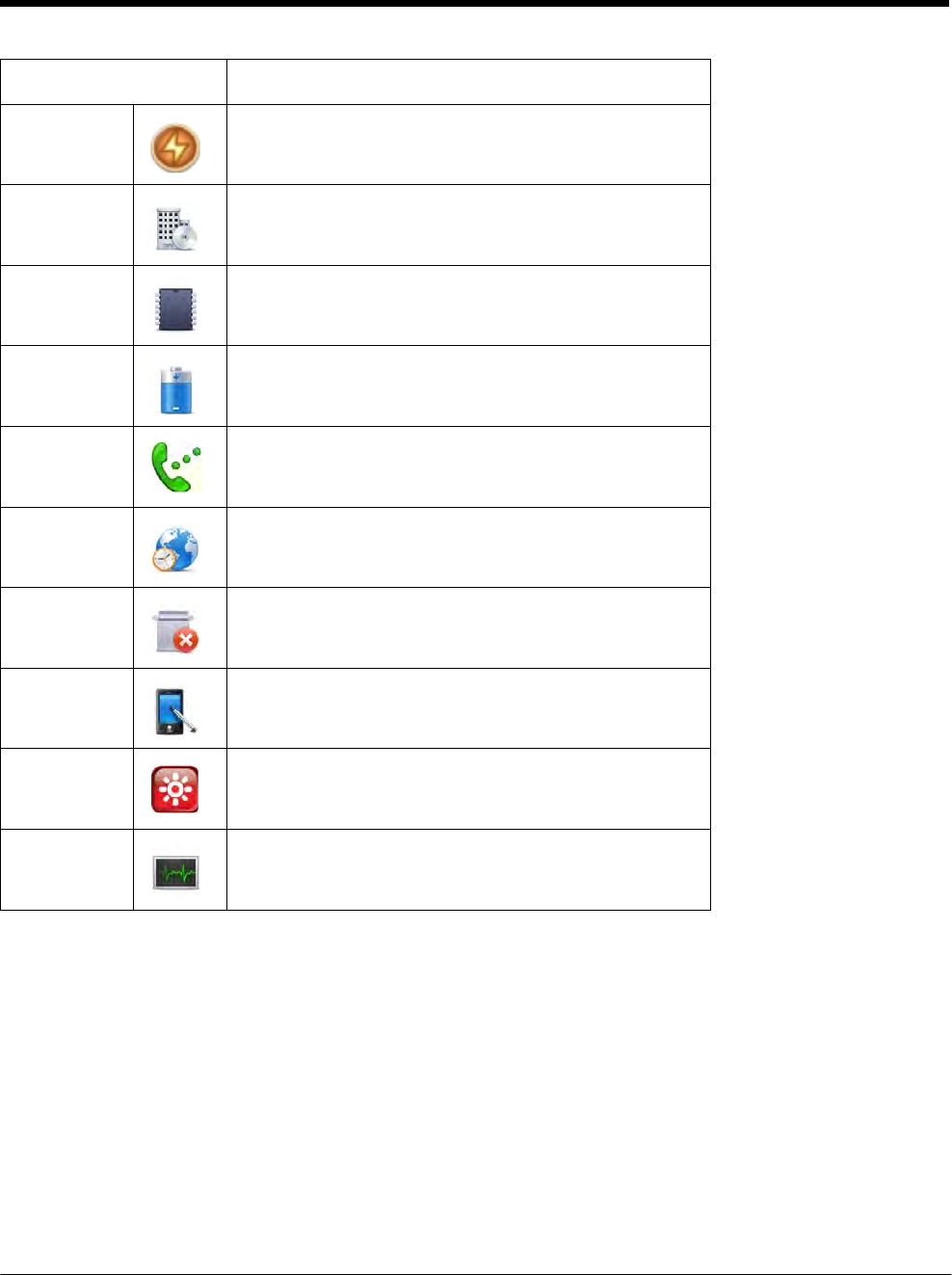
DRAFT COPY 11/11/11
7 - 8
Icon See Page
Five Volt
Control
See Five Volt Control on page 7-12.
Managed
Programs
See Managed Programs on page 7-13.
Memory See Memory on page 7-14.
Power
See Power on page 7-15.
RIL
See RIL on page 7-15.
Regional
Settings
See Regional Settings on page 7-15.
Remove
Programs
See Remove Programs on page 7-16.
Screen See Screen on page 7-17.
Smart
Sensors
See Smart Sensor on page 7-12.
Task
Manager
See Task Manager on page 7-18.
About
The About system setting displays specific information about the terminal. It contains three screens:
Version Screen Displays the information about the software, operating system, and processor.
Device ID Screen Displays the information the terminal uses to identify itself to other devices. It can be important
to know this information if the Dolphin terminal is going to be part of a networked system of
devices.
Device name: Displays the system’s default name. This is the name used by ActiveSync.
Description: Displays the description of the device ID.
Copyrights Screen: Displays important copyright information.
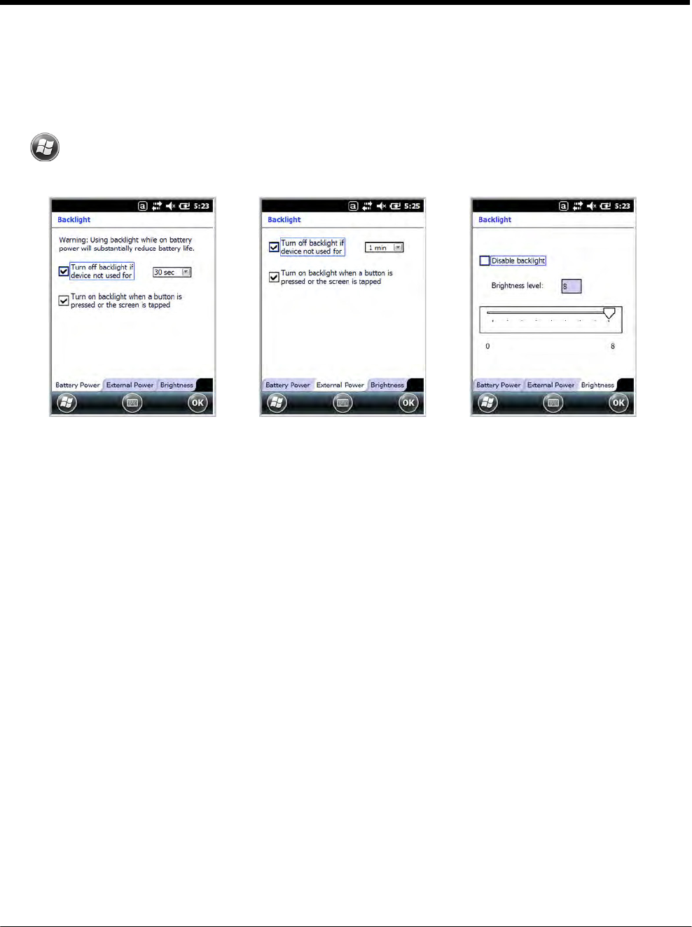
DRAFT COPY 11/11/11
7 - 9
Backlight
The Backlight system setting enables you to customize backlight functionality for the display. The back-
light for the color display is user-defined. The Backlight system setting screen contains three tabs: Bat-
tery Power, External Power, and Brightness.
Tap > Settings > System > Backlight.
Battery Power Tab External Power Tab Brightness Tab
The Battery Power tab determines the backlight timeout when the terminal is running on battery power.
The External Power tab determines the backlight timeout when the terminal is running on external
power.
The options on the power tabs are the same.
Turn off backlight: Select how many minutes you want to elapse before the backlight
automatically turns off.
Turn on backlight: Select this option if you want the backlight to turn on when the button is
pressed or the touch screen is tapped.
The Brightness tab determines the backlight intensity. Move the slider to set the intensity of the back-
light. The default is 8.
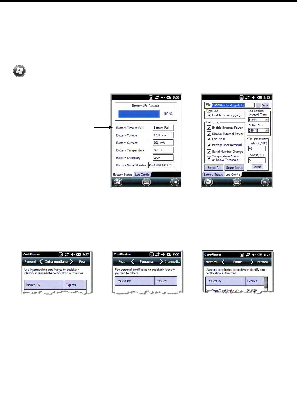
DRAFT COPY 11/11/11
7 - 10
Battery
The Battery system settings menu contains two tabs: Battery Status and Log Config. The Battery Sta-
tus tab provides the status of the main battery pack (e.g., Battery Time to Full or Battery Time to Empty,
Voltage, Current, Temperature, Chemistry, and Serial Number). The Log Config Tab allows you to con-
figure the BatteryLogFile.
Tap > Settings > System > Battery
Battery Status Tab Log Config Tab
When external power is
supplied to the terminal,
“Battery Time to Full” is
listed. When power is
supplied by the battery
pack, “Battery Time to
Empty” is listed.
Certificates
Certificates shows you the certificates that are recognized by the operating system. It contains three
screens.
Intermediate Screen Personal Screen Root Screen
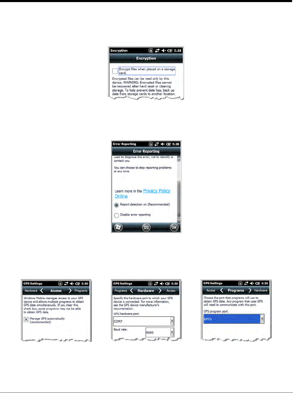
DRAFT COPY 11/11/11
7 - 11
Encryption
Encryption gives you the option of encrypting files placed on storage cards so that those files cannot be
read by any other device.
Error Reporting
Error Reporting gives you the option of enabling or disabling the error reporting function of Windows
Embedded Handheld 6.5.
External GPS
External GPS determines which port a third-party GPS software application can use to access the GPS
receiver.
Access Screen Hardware Screen Programs Screen
Note: You need the installation parameters from the GPS manufacturer to configure the connection.
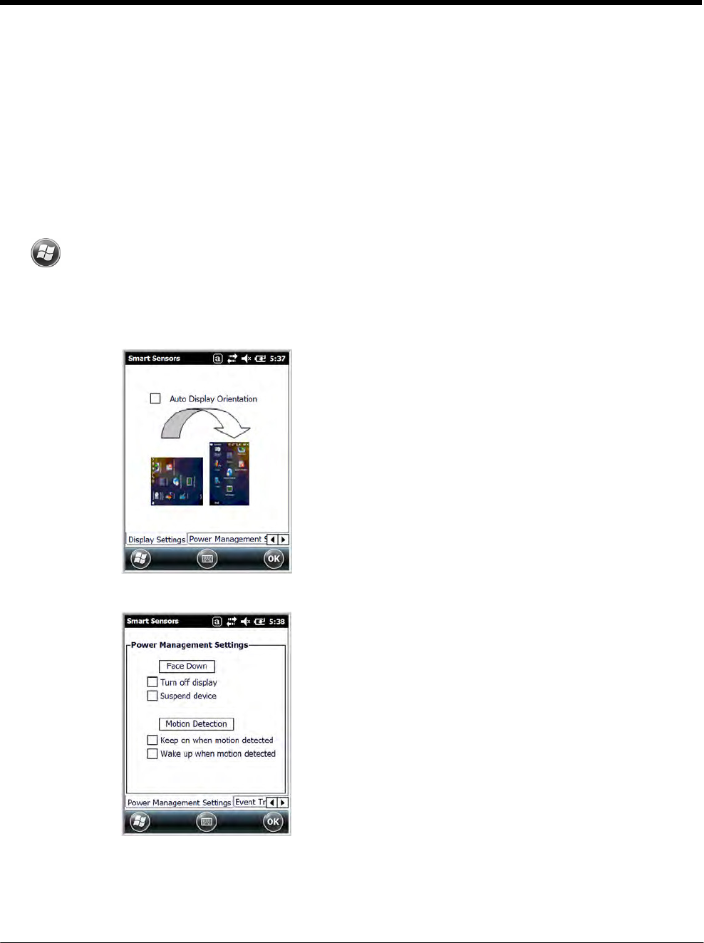
DRAFT COPY 11/11/11
7 - 12
Five Volt Control
Five Volt Control gives you the option to manually enable 5V output to supply power to an external
device. By default, 5-Volt Output automatically turns on when AC power is applied to the terminal. If you
want to use a USB memory stick without AC power, then you must manually turn on the 5-Volt Output.
Do not leave 5-Volt output enabled when you are not using it to supply power to an external device.
Smart Sensor
The Smart Sensor configuration utility enables you to configure the Dolphin’s integrated accelerometer,
and motion settings.
Tap > Settings > System > Smart Sensor.
Motion Settings
Motion Settings enable you to customize how the terminal responds to motion and object orientation for advanced
power management.
Display Settings enables or disables Auto Display
Orientation. When enabled, the Dolphin's display
automatically switches between portrait and landscape
depending on how you hold the terminal.
Power Management Settings customize how the terminal
responds to object orientation and motion.
• Save power by turning off the display or suspending the
terminal when it is placed face down.
• Modify the Motion Detection settings to wake the terminal
from suspend mode or prevent the terminal from entering
suspend mode when motion is detected.
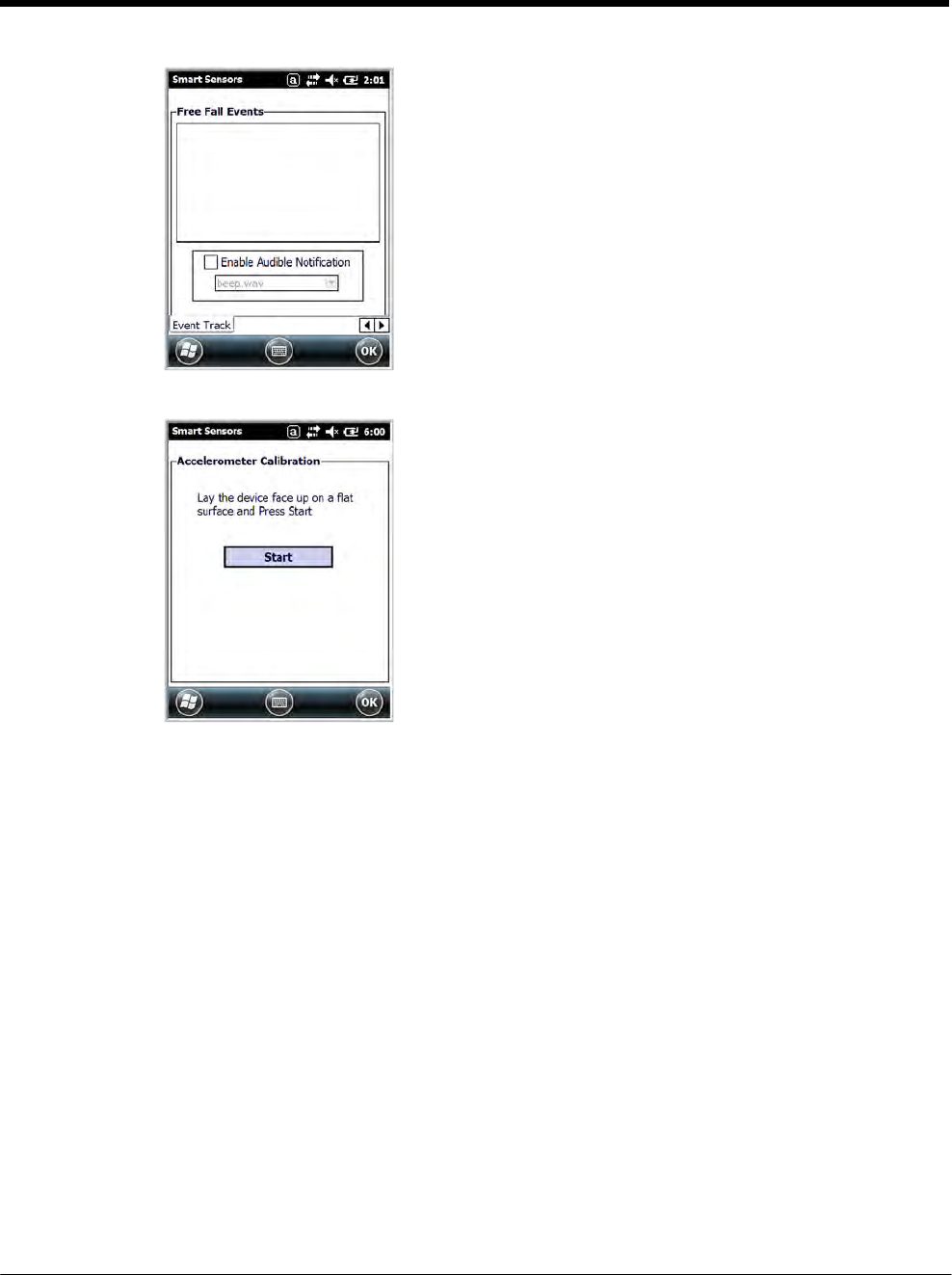
DRAFT COPY 11/11/11
7 - 13
Event Track displays an event log summary of detected free
fall events exceeding 2 ft. over 250 ms. The summary includes
the time, date, and duration of the most recent 50 events.
Several options are provided for audible notification of free fall
events.
Accelerometer Calibration
Tap Start to calibrate the integrated accelerometer sensor
used for motion detection. When calibration is complete, the
"Accelerometer Calibration Finished!" message window
appears.
Managed Programs
Managed Programs are a list of programs that are managed if enrolled to enterprise domain. Managed
Programs is the client-side that works with the server product System Center Mobile Device Manager
(MDM). MDM consists of MDM Gateway Server and one or more computers that run MDM Device Man-
agement Server; MDM Enrollment Server; and Microsoft SQL Server® 2005 databases.
It lets system administrators:
• provide an authenticated connection to Line of Business (LOB) applications, managed Group Policy,
and application packages.
• use Group Policy and software packages to manage the enrolled Windows phones (enforce policy,
wipe devices, etc.).
• manage the requests for and retrieving of certificates for devices and for creating the Active Directory®
Domain Service objects that represent these devices. By using these objects, you can manage the
devices as if they were members of a domain.
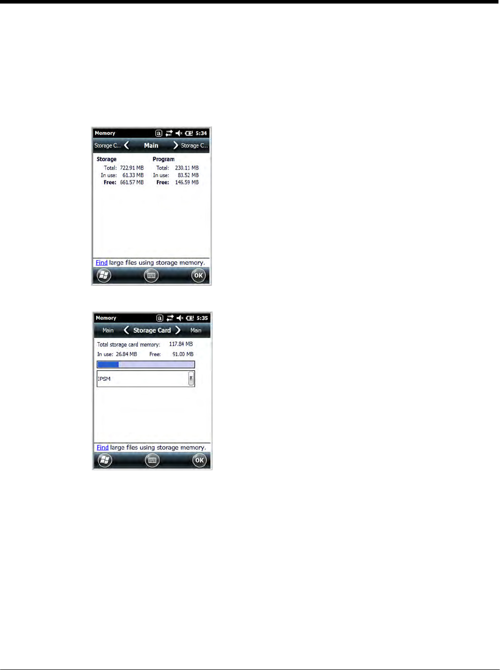
DRAFT COPY 11/11/11
7 - 14
Memory
The Memory applet shows the capacity and usage of the Storage and Program portions of the Flash file
system. The Storage portion includes the IPSM folder, which can be detailed under the Storage
Card
tab.
When the Program portion becomes too full, you can use the Task Manager to remove any unneces- sary
tasks.
Main Screen
This screen displays the usage statistics of the flash
memory.
Storage Card Screen
This screen displays the current capacity and usage sta-
tistics of the selected memory type: IPSM, RAMDISK or
Storage Card.
Select the memory type from the drop-down list. IPSM is
selected by default.
Total storage card memory = The total MB of memory
capacity of the IPSM, RAMDISK or Storage Card.
In use = The MB currently being used.
Free = The MB that is still available for use.
IPSM—Short for Internal Persistent Storage Manager. Data or programs stored in the
IPSM are not affected when the operating system is upgraded. Autoinstall programs,
for example, are stored in \\IPSM\Honeywell\Autoinstall so that they are always
installed after an operating system upgrade or factory reset. Contact a Honeywell
technical support representative for more information on how to perform a factory
reset. For contact information, see Technical Assistance on page 18-2.
RAMDISK—Is a disk image that resides in RAM and threfore is faster than IPSM or
any other system named folder. RAMDISK is cleared when a hard reset or a factory
reset is performed.
Storage Card—You can install one memory card in Dolphin terminals (see Installing
a SIM Card and/or Memory Card on page 3-16). If a storage card is installed in the
terminal, you can select it in the drop-down list and see capacity and usage statistics
for the card.
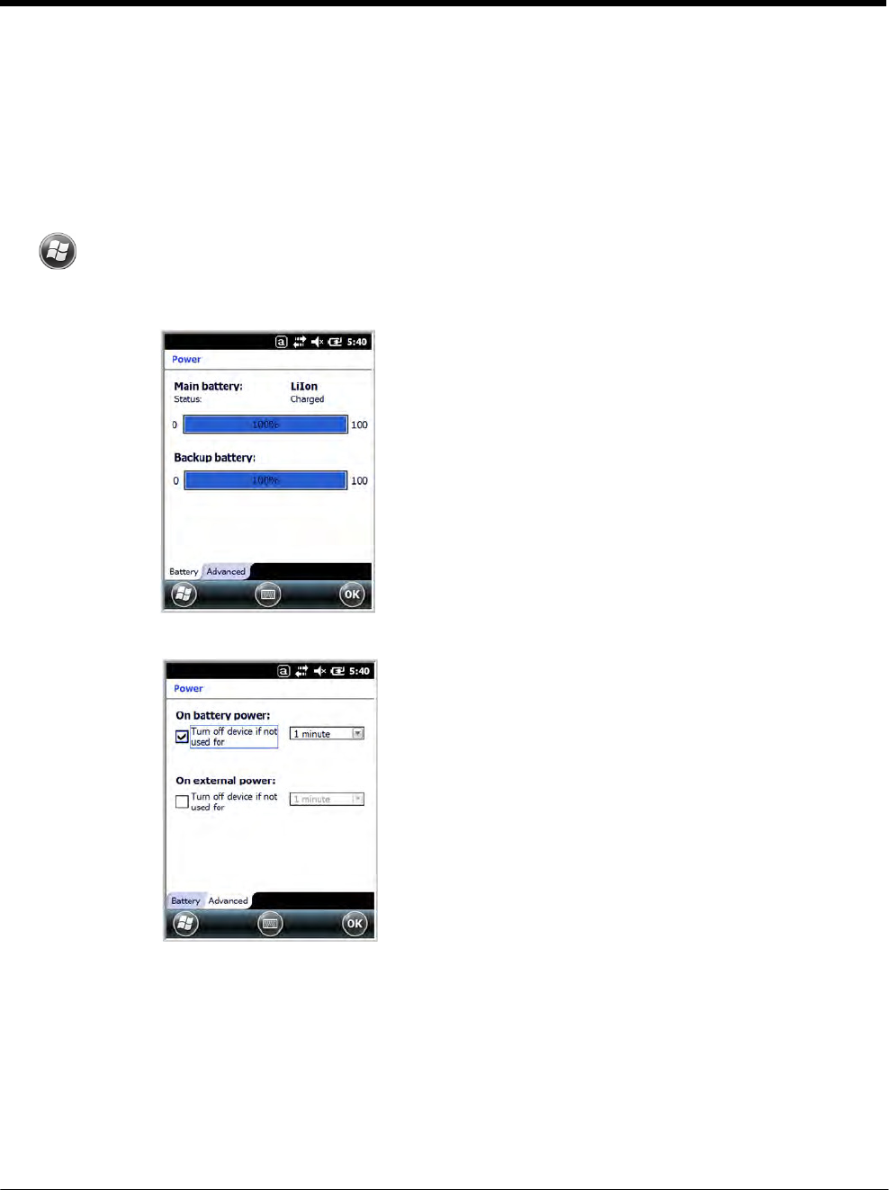
DRAFT COPY 11/11/11
7 - 15
RIL
The RIL Information screen displays useful statistics for the GSM WAN Voice module (PH8). To verify
whether or not the GSM radio is enabled, check the Dolphin Wireless Manager (see page 8-4).
Power
Power system settings contains two tabs: Battery and Advanced
Tap > Settings > System > Power
Battery Tab
The battery tab displays the power level status of the
main battery and the status of the backup battery.
Note: The Backup Battery gauge registers either 0% or 100%.
The percentage is not an indication of the level of charge
remaining on the backup battery. An installed and
functional battery registers 100%. A total discharge or a
battery error registers 0%.
For detailed information on the main battery pack, see
Battery on page 7-10.
Advanced Tab
Determines power time-outs.
For On battery power, select from the drop-down list, the
number of minutes of inactivity you want to pass before the
terminal powers off when running on battery power.
For On external power, select from the drop-down list, the
number of minutes of inactivity you want to pass before the
terminal powers off when running on external power.
Note: When the terminal “powers off”, it enters Suspend Mode, see page 2-11 for additional information.
Regional Settings
Regional Settings enables you to customize the appearance and formatting to your geographic region.
Specifically, you can customize numbers (i.e., number of decimal places allowed), currency (i.e.,using
the $ or € symbol), time, and date. These specifications apply to all screens, including the Home screen.
The Region tab displays an overview of the region selected in the drop-down list at the top.
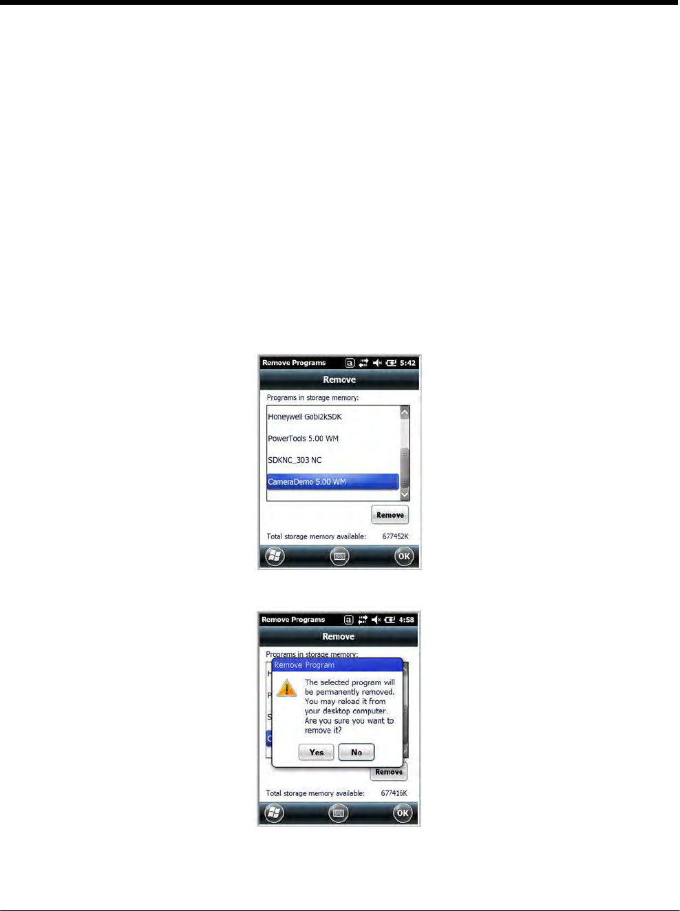
DRAFT COPY 11/11/11
7 - 16
The terminal is loaded with a number of pre-programmed regional settings. Select one from the list and
the results appear on the screen. To see specific settings or to change a specific setting, tap on one of
the items on the horizontal scroll bar (i.e., Region, Number, Date), make the change, and tap OK to
save.
Remove Programs
Remove Programs enables you to remove programs installed on the terminal. Any program (usually CAB
or DLL files) stored in the \\IPSM\Honeywell\Autoinstall folder re-installs after a software upgrade or a
factory reset. If a program is manually removed using the Remove Programs application, the program
does not re-install on a hard or soft reset.
Note: A program (file) does not automatically install if it is added to the \\IPSM\Honeywell\Autoinstall folder and a
hard or soft reset is performed. For information on program installation, see Installing Additional Software on
page 8-8.
For information about the system resets, see Resetting the Terminal on page 2-11. See Honeywell sup-
port for more information on how to perform a factory reset.
1. Tap Remove Programs. In the list, select the program you want to remove.
2. Tap Remove. The following message appears:
3. Tap Yes. Wait while the program is removed.
4. Verify that the program no longer appears in the list.
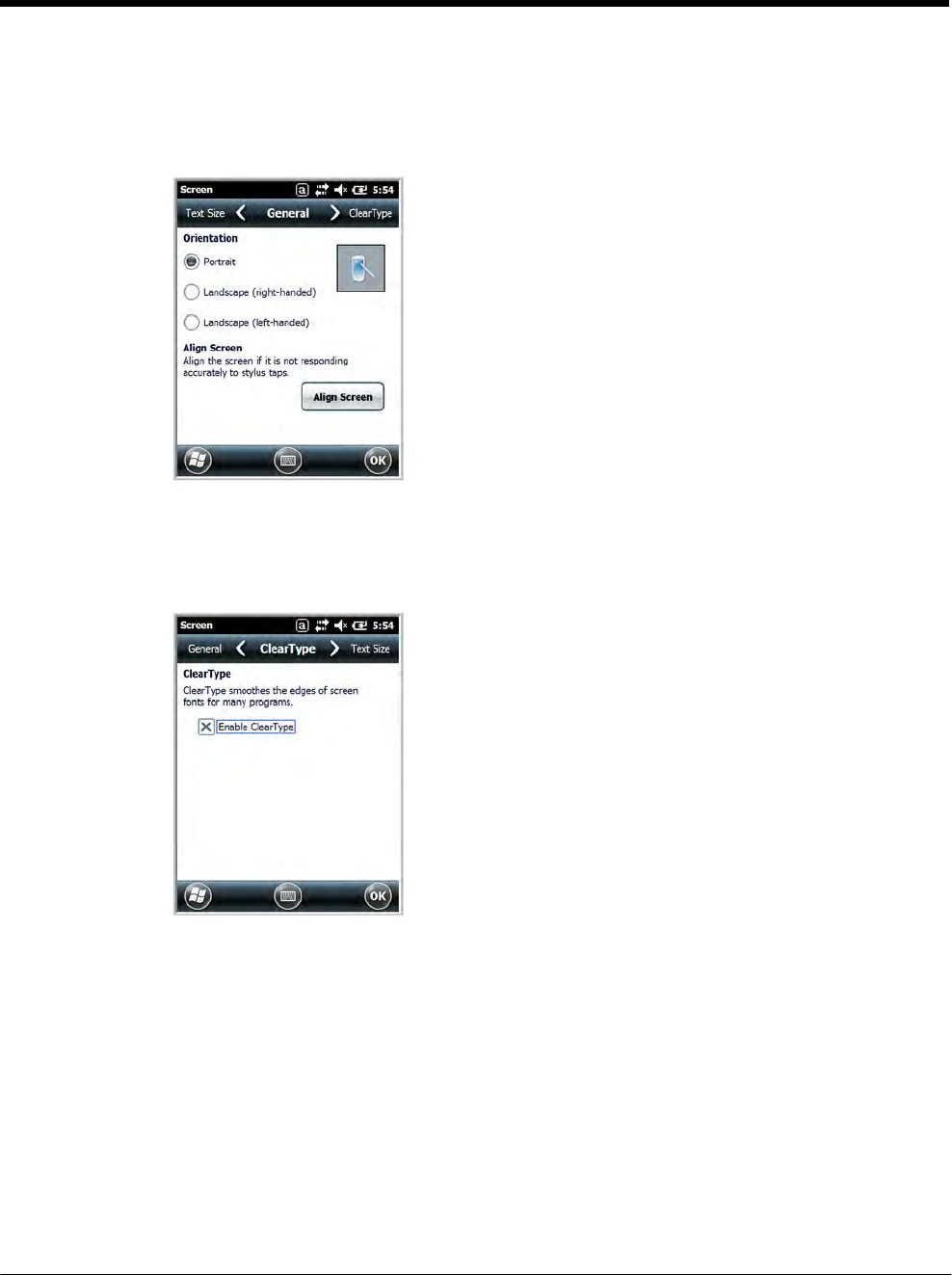
DRAFT COPY 11/11/11
7 - 17
Screen
The Screen system setting contains three screens: General, Clear Type, and Text Size.
General Screen
Orientation
The General screen enables you to set the dynamic screen
rotation. Three choices of screen orientation are supported:
Portrait, Landscape (right-handed), and Landscape (left-
handed).
ClearType Screen
Align Screen
The General Tab also allows you to re-align the screen.
You need to re-align the screen if tapping buttons or icons with
the stylus no longer seems to work appropriately.
Tapping Align Screen brings up the align screen window
where you are guided to tap a target several times. This re-
calibrates how the touch screen receives input.
• Alignment should always be performed with a stylus
designed for touch panel applications. The small point is
required for accurate calibration.
• Press the stylus firmly into the center of the cross-hair target
once and release. Do not “double-tap” the target.
The display supports ClearType font rendering, which is a
Microsoft technology that dramatically increases the readability
of text on LCD displays.
To enable ClearType font rendering, select Enable ClearType
and tap OK.
For more information about ClearType font rendering, visit:
www.microsoft.com/typography/WhatIsClearType.mspx.
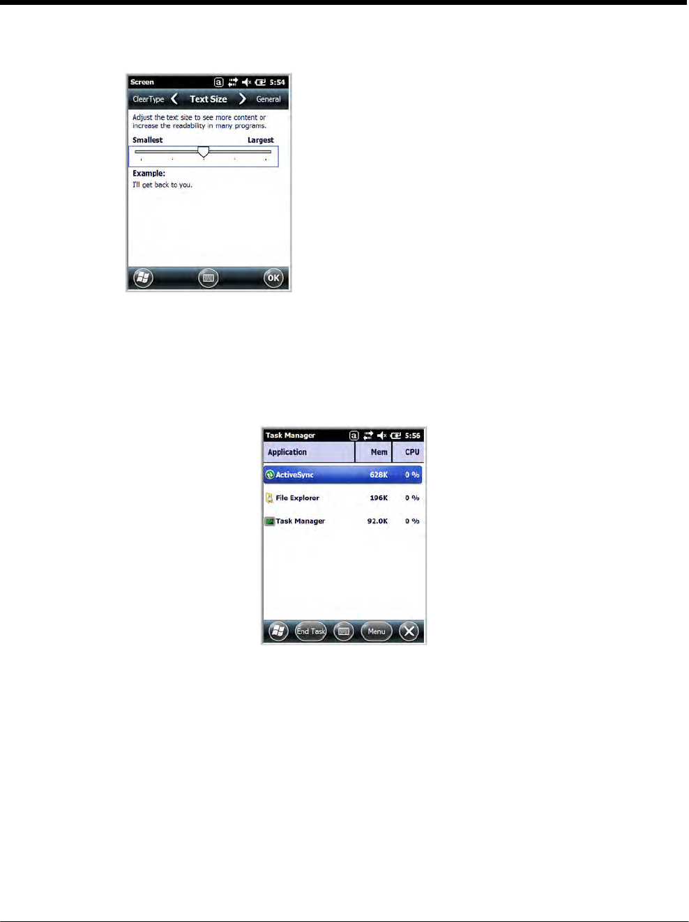
DRAFT COPY 11/11/11
7 - 18
Text Size Screen
The Text Size screen enables you to perform font scaling within
certain views of the:
• Home screen,
• Contacts,
• Calendar,
• Messaging, and
• Tasks.
Font scaling means that you can increase or decrease the
point size of the font on application windows.
To change the font size, move the slider toward Smallest or
Largest. The Example text changes to reflect the font change.
Tap OK to save the new font size setting.
Task Manager
The Task Manager provides information about applications and processes running on your mobile com-
puter. You can use the Task Manager to monitor the memory and CPU usage of specific applications and
processes. Check the Task Manager when you are receiving out of memory errors or when the mobile
computer is running slowly.
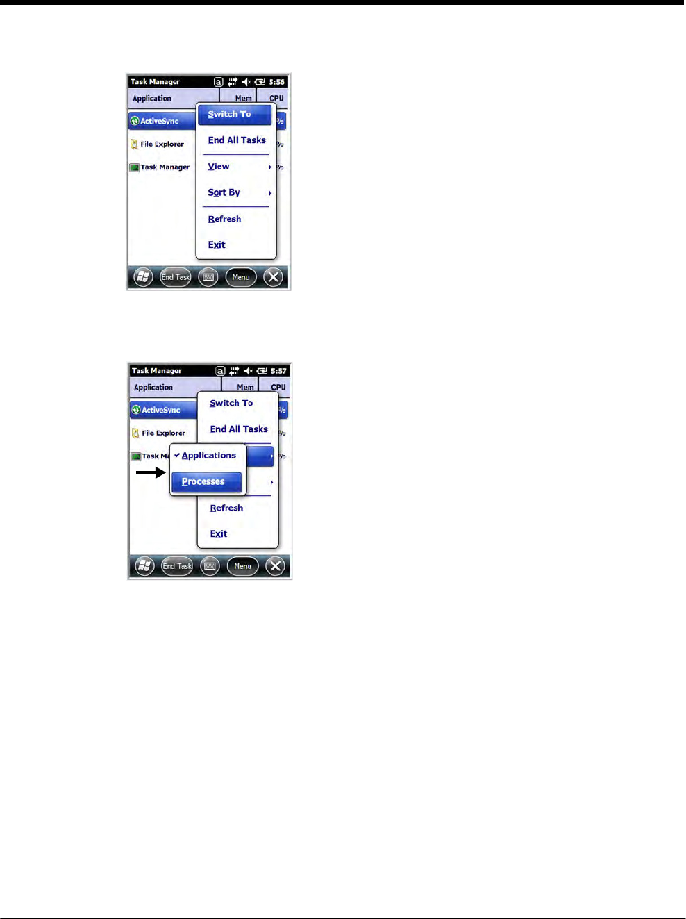
DRAFT COPY 11/11/11
7 - 19
Using the Task Manager
Applications To view the status of the programs running on your
mobile computer, tap the Menu button at the bottom of
the screen, then tap View > Applications.
From the application list, you can:
• Tap and hold on an application, then tap Switch To on
the pop-up menu.
• Tap and hold on an application, then tap End Task or
End All Tasks on the pop-up menu.
Note: Anytime you stop a running program, it frees up memory. To free up memory, return to the running
program, save your data, and close the application.
Processes To view information about the processes running on the
mobile computer, tap the Menu button at the bottom of
the screen, then tap View > Processes.

DRAFT COPY 11/11/11
7 - 20
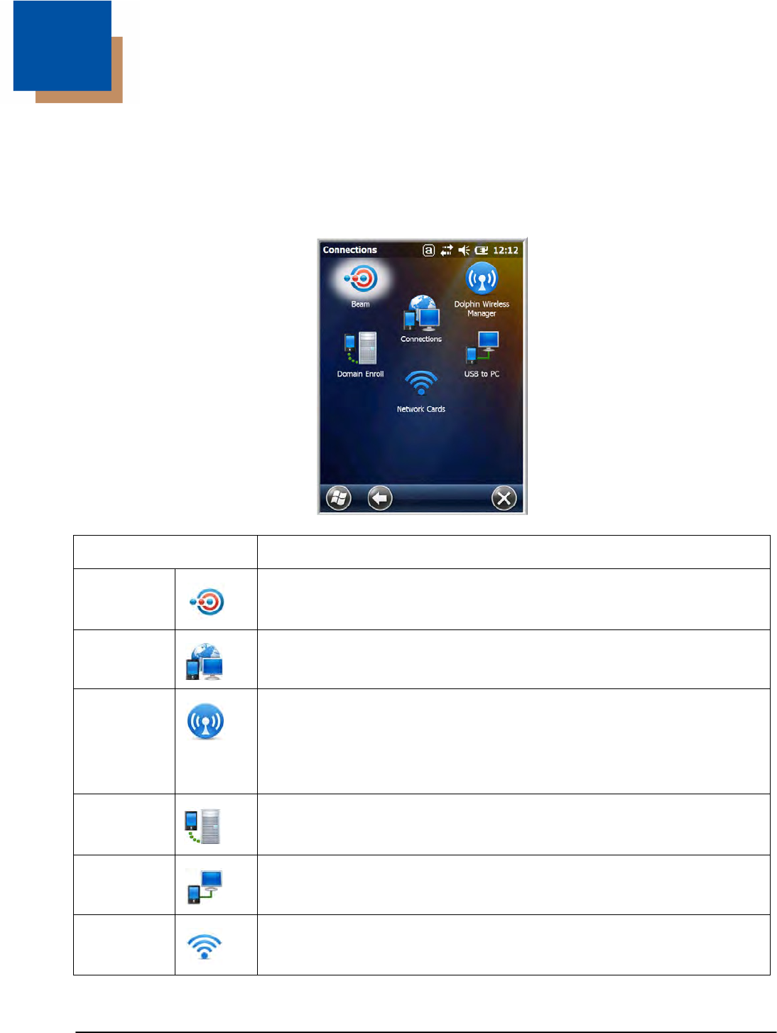
8 - 1
8 DRAFT COPY 11/11/11
Communication
Connections Menu
The Connections system setting provides access to the terminal’s various wireless communication
options.
Icon Tapping this icon…
Beam
Enable the terminal to receive incoming beams from devices using Bluetooth
wireless technology. See Working with the Bluetooth Radio on page 10-1.
Connections
Opens Microsoft’s connections manager. See Connections Manager on page 8-2.
Dolphin
Wireless
Manager
Manages the wireless radios installed in the terminal. See Dolphin
Wireless Manager on page 8-4.
Note: The Dolphin Wireless Manager icon may not appear on the Connections
menu on terminals running Microsoft Windows Embedded Handheld 6.5
Classic. For information on how to access the Dolphin Wireless Manager,
see page 8-4.
Domain
Enroll
Opens the Enrollment screen for connecting your phone with company resources.
Note: System administrator password is required for domain enrollment.
USB to PC Enables advanced wired USB to PC communication via sync sofware. See
Connecting and Synchronizing the Terminal and Workstation on page 8-6.
Network
Cards
Manage Network card settings.
Note: All server-assigned IP addresses use Dynamic Host Configuration Protocol (DHCP).
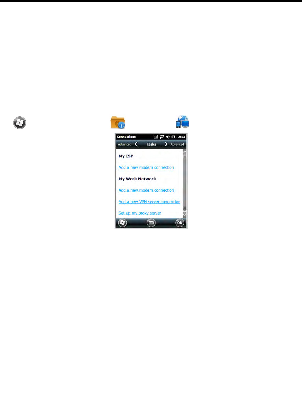
DRAFT COPY 11/11/11
8 - 2
Connections Manager
Microsoft’s Connections Manager sets up multiple network connections to Internet Service Providers
(ISPs) via external modem.
Do NOT enter connection parameters in the Connections Manager if:
• you are using one of the on-board wireless radios to connect to a network. The Dolphin terminal uses
the settings from each radio’s configuration utility to connect. The connections manager is used
primarily to setup WAN modem dial up connections.
• you are using Wireless Zero Config. By default, WZC is disabled on Dolphin terminals.
To Access the Connections Manager
Tap > Settings > Connections > Connections .
Tasks
The Tasks screen enables you to initially configure, and then manage network settings when using a
modem. Select an item in this list and then complete the setup screens that follow with the appropriate
information for your network.
My ISP
The links under this heading enables you to add and manage modem connections to an ISP. To com-
plete the setup screens, obtain the following information from your ISP:
• ISP dial-up access telephone number
• Username
• Password
• TCP/IP settings
My Work Network
These links enable you to establish the following connections types:
• Modem
• Virtual Private Network (VPN)
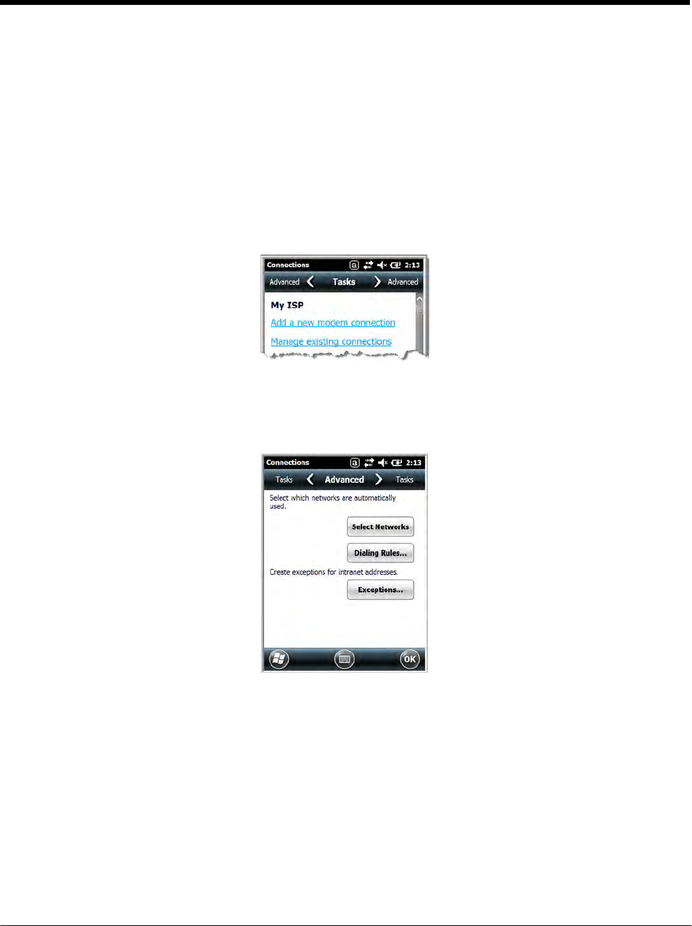
DRAFT COPY 11/11/11
8 - 3
• Proxy server connection
Note: If you are connected to your ISP or private network during synchronization, the terminal should
download the proper proxy settings during synchronization with the workstation. If these settings are not
on your workstation or need to be changed, ask your ISP or network administrator for the proxy sever
name, server type, port, type of Socks protocol used, and your user name and password.
To complete the setup screens, obtain the network parameters from your system administrator.
Modify an Existing Connection
Manage Existing Connections appears on the Connections tab after at least one network connection
has been established.
Tap Manage Existing Connections on the Horizontal scroll and follow the setup screens.
Advanced
The Advanced screen enables you to select the default network, dialing rules, and IP address exceptions
for modem connections.
Note: You should not need to change Advanced settings because most ISPs now use DHCP addresses.
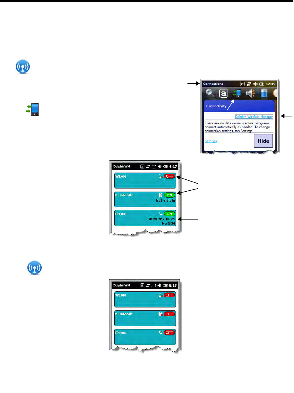
DRAFT COPY 11/11/11
8 - 4
Dolphin Wireless Manager
The Dolphin Wireless Manager provides a centralized interface that enables and disables all the on-
board radios. Each radio has its own configuration program. The Dolphin Wireless Manager also pro-
vides shortcuts to the configuration utilities for each radio.
Tap on the Home screen to access the Dolphin Wireless Manager.
OR
1. Tap once on the Title bar to access the Horzontal Scroll bar.
2. Tap .
3. Select, “Dolphin Wireless Manager”.
Dolphin Wireless Manager Window
These buttons show you the
state of the radio.
If applicable, information about
the radio appears when the
radio is
activated.
Enabling the Radios
1. Tap on the Home screen to access the Dolphin Wireless Manager.
2. Tap anywhere inside the rectangle of the radio you want to enable.
3. The radio begins activating.
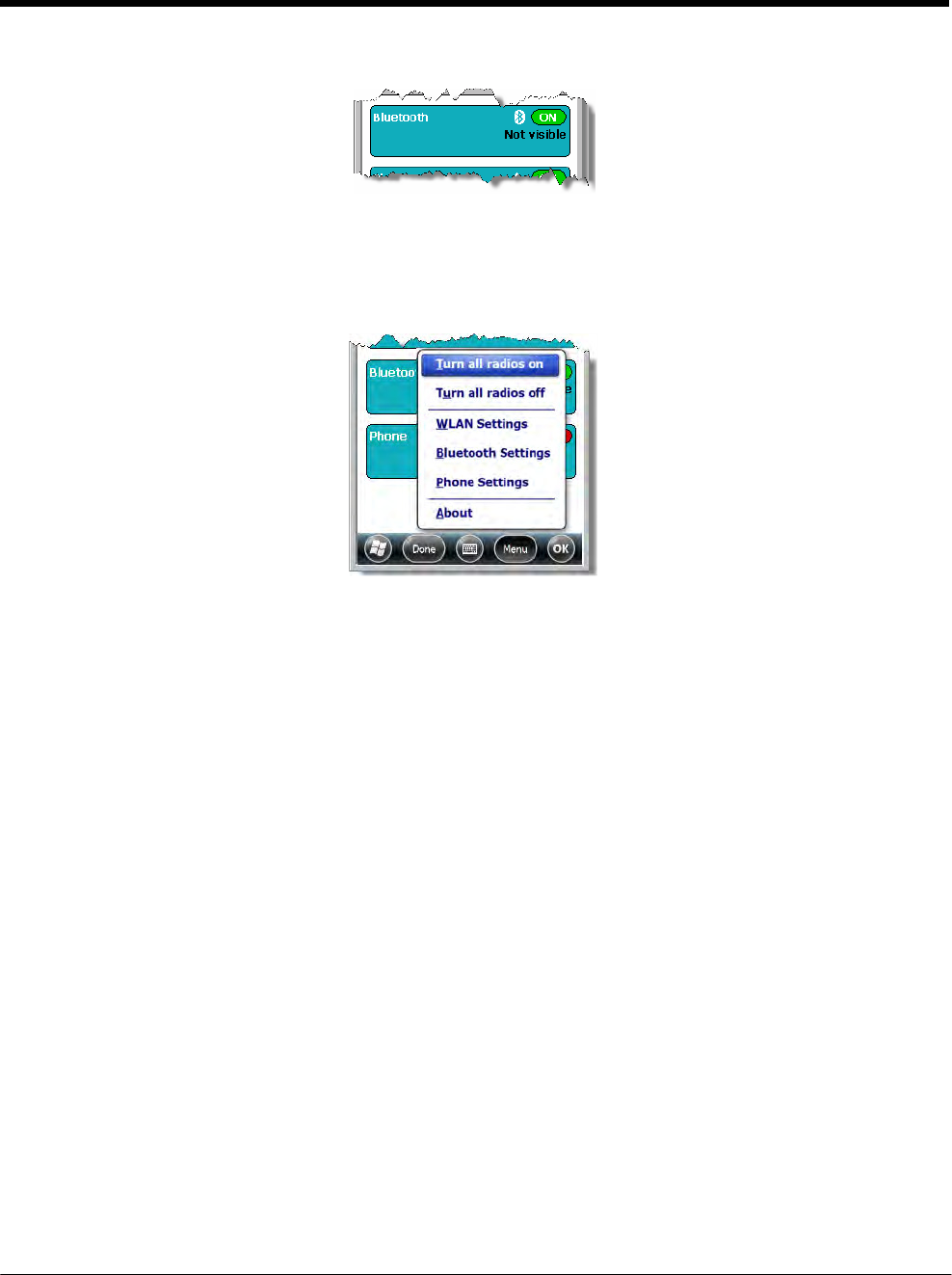
DRAFT COPY 11/11/11
8 - 5
4. When the radio is activated (i.e., transmitting a signal), the OFF button changes to ON.
Note: If applicable, information about the radio appears in the rectangle.
Accessing Radio Configuration Utilities
Each radio has its own configuration utility that you can access by tapping Menu on the tile bar.
Radio Type Menu Option
802.11a/b/g/n Tap WLAN Settings and the Honeywell WLAN Security Supplicant opens.
The Honeywell WLAN Security Supplicant User’s Guide is available for
download from the Dolphin 7800 product page at www.honeywellaidc.com.
Bluetooth Tap Bluetooth Settings and the Bluetooth Settings screen opens.
For details, see Working with the Bluetooth Radio on page 10-1.
GSM/HSDPA/UMTS/GPRS/
EDGE
Tap Phone Settings and the Phone opens.
For details, see Working with Wireless Wide Area Networking (WWAN) on
page 9-1.
GSM/CDMA Tap Gobi Settings and the Gobi Manager opens.
For details, see Gobi Manager on page 9-11.
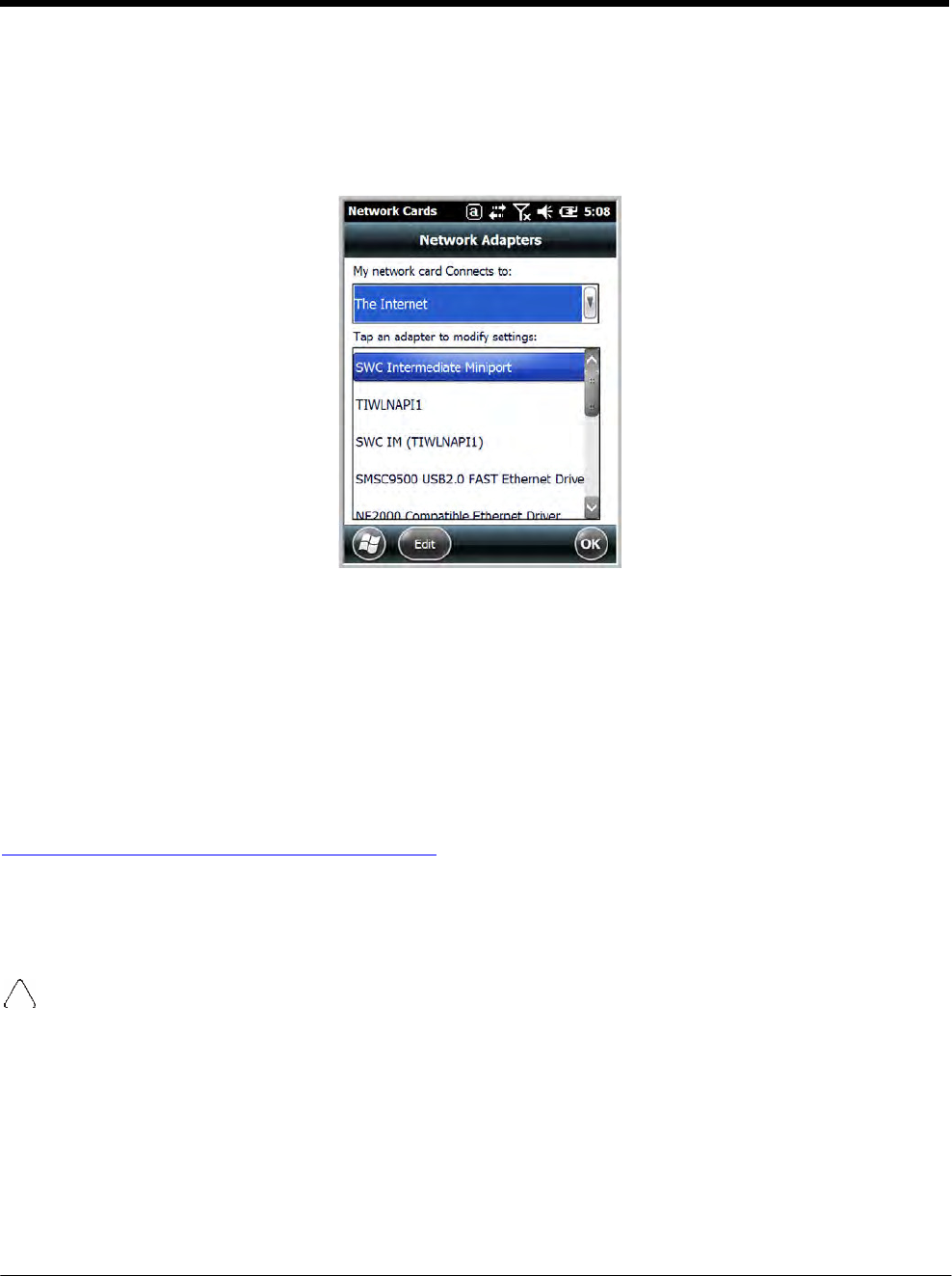
DRAFT COPY 11/11/11
8 - 6
Network Cards
The Network Cards screen allows you to set and configure the type of Network Adapter the Network
card in the terminal uses. You can modify the adapter settings (e.g., Name Servers or IP address) by
tapping on the adapter type or highlighting the adatpter and tapping Edit at the bottom of the screen.
Connecting and Synchronizing the Terminal and Workstation
To synchronize data between the terminal and the workstation, ActiveSync (version 4.5 or higher) or
Windows Mobile Device Center (WMDC) must be installed and configured for the appropriate communi-
cation type on the host workstation (Windows-based PC) and the Dolphin terminal. Dolphin terminals
ship with ActiveSync already installed. Therefore, if ActiveSync or WMDC is already installed on the host
workstation, you just need to connect the Dolphin terminal to the host workstation (via Dolphin periph-
eral) to initiate communication.
If ActiveSync (4.5 or higher) or WMDC is not installed on the host workstation, you can download and
http://go.microsoft.com/fwlink/?LinkId=147001 the most current version of the software from the
Microsoft Web site (http://go.microsoft.com/fwlink/?LinkId=147001).
Note: ActiveSync on your Dolphin terminal works with WMDC on host workstations running Windows Vista or
Windows 7 and with ActiveSync on host workstations running Windows XP. For detailed information on
ActiveSync and WMDC visit the Microsoft Windows Phone Web site.
When communicating via ActiveSync or WMDC, your terminal is designed to be connected to the host
workstation with a communication peripheral sold/manufactured by Honeywell, such as the charge/
communication cable. Use of any peripheral not sold/manufactured by Honeywell may cause damage not
covered by the warranty.
Capabilities
• Back up and restore your device data.
• Copy (rather than synchronize) files between your device and workstation.
• Control when synchronization occurs by selecting a synchronization mode. For example, you can
synchronize continually while connected to your workstation or only when you choose the synchronize
command.

DRAFT COPY 11/11/11
8 - 7
• Select which information types are synchronized, controling how much data is synchronized. For
example, you can choose how many weeks of past appointments you want synchronized.
Communication Types
The 7800 terminal supports Hi-Speed USB communication (USB 2.0) via ActiveSync through the I/O
Connector (see page 3-10) on the bottom panel of the terminal. The maximum data transfer rate is 480
Mbps. A USB cable and a Honeywell hardware peripheral (e.g., HomeBase) allow the terminal to com-
municate with a workstation or to networked through a USB hub. The Dolphin terminal defaults to USB
communication out of the box.
Hardware Requirements for Setup
• Dolphin communication peripheral (e.g., HomeBase, eBase, USB Communication/Charge Cable) and
power supply.
• A USB cable if one is not supplied with your Dolphin communication peripheral.
Software Requirements for Communication
• ActiveSync (v4.5 or higher) or Windows Mobile Device Center installed and configured on the host
workstation (PC), see Setting Up the Host Workstation on page 8-7.
Note: ActiveSync or Windows Mobile Device Center must be setup on your workstation before you initiate
synchronization from the terminal for the first time.
• Windows 98 Second Edition, Windows Me, Windows 2000, Windows NT (4.0 SP6 or higher), Windows
XP, Windows Vista, and Windows 7 operating systems.
Setting Up the Host Workstation
To synchronize data between the terminal and the workstation, ActiveSync (v4.5 or higher) or Windows
Mobile Device Center must be configured for same communication type on both the host workstation
and the Dolphin terminal.
ActiveSync
Verify that ActiveSync is configured to use the appropriate communication type.
1. In the ActiveSync window on your workstation, select File > Connection Settings.
2. Check the box next to “Allow USB connections”.
Connecting the Dolphin Terminal to the Host Workstation
After setting up both the workstation and the terminal:
1. Connect the Dolphin terminal to the workstation using a Dolphin communication peripheral.
2. ActiveSync or Windows Mobile Device Center should open and connect automatically to the Dolphin
terminal.

DRAFT COPY 11/11/11
8 - 8
Synchronizing with the Host Workstation
After setup, synchronization begins automatically whenever the terminal’s mechanical connector con-
nects to a Dolphin peripheral that is connected to a host workstation with ActiveSync or Windows Mobile
Device Center installed. For additional information visit the Microsoft Phone Web site (http://go.micro-
soft.com/fwlink/?LinkId=147001).
Exploring the Terminal from the Workstation
ActiveSync
1. Open the main ActiveSync window (on the desktop).
2. Click Explore. This opens the Mobile Device folder for the terminal in Windows Explorer.
3. The Dolphin terminal is now treated as a mass storage device, and transferring files is as simple as
dragging and dropping or copying and pasting.
Windows Mobile Device Center
1. Open Windows Mobile Device Center (on the desktop).
2. Click File Management. This opens the Mobile Device folder for the terminal.
3. The Dolphin terminal is now treated as a mass storage device, and transferring files is as simple as
dragging and dropping or copying and pasting.
Installing Additional Software
Dolphin terminals ship with the operating system, radio drivers, and custom Honeywell software already
installed. These are the default programs that install when your terminal first boots up. You can install
additional software programs to the terminal provided that the following parameters are met:
• The software program was created for a Windows Embedded Handheld 6.5 device.
• The terminal has enough memory to store and run the program.
• The program has an EXE, CAB, or DLL extension.
When selecting programs, verify that the program and version of the program are designed for the Win-
dows Embedded Handheld 6.5 and the terminal’s processor. You can verify your processor by tapping
> Settings > System > About > Version. Make a note of the information in the Processor field.
To install additional software, you can use the communication options described in this chapter.
• Adding Programs Using ActiveSync or Windows Mobile Device Center, see page 8-8.
• Adding Programs Using the Internet, see page 8-10.
Adding Programs Using ActiveSync or Windows Mobile Device Center
Generally, software for Windows Embedded Handheld devices must be installed to the host workstation
first, then transferred to the Dolphin terminal.
Note: An active Microsoft ActiveSync or Windows Mobile Device Center connection between a host workstation and
the Dolphin terminal is required to add programs. For additional information, see Connecting and
Synchronizing the Terminal and Workstation on page 8-6.

DRAFT COPY 11/11/11
8 - 9
1. Download the program to the workstation from either the Internet or the install CD. You may see a
single *.exe or setup.exe file, a *.cab file, or a *.dll file.
Note: There may be several versions of files for different device types and processors. Select the file that
matches the terminal’s processor.
2. Read any installation instructions, Read Me files, or documentation that comes with the program.
Many programs provide special installation instructions.
3. Connect the terminal to the workstation via a Dolphin communication peripheral.
If the File is an Installer (*.exe or *.setup.exe)
An installer program is one that installs on the workstation and the terminal simultaneously; one process
installs to both devices.
1. On the workstation, double-click the *.exe or setup.exe file. The installation wizard begins.
2. Follow the directions on the workstation screen. The installation process includes transferring the
software to the Dolphin terminal.
If the File is Not an Installer
Some programs cannot be installed on PCs because they are designed exclusively for Windows Embed-
ded Handheld devices. In these cases, the appropriate files must be stored on the host workstationand
transferred to the terminal via ActiveSync Explore or Windows Device Mobile File Management.
Note: You know that the program is not an installer because an error message stating that the program is valid but
designed for a different type of computer appears when you try to install the program on the workstation.
1. If you cannot find any installation instructions for the program in the Read Me file or documentation,
do one of the following:
a. Open ActiveSync and click Explore, or
b. Open Windows Mobile Device Center and click File Management
2. On the workstation, navigate to the workstation folder containing the program file(s). Copy and
paste the file(s) into the Program Files folder on the terminal.
• If you want the program to be part of the Autoinstall that occurs after a factory reset or software
upgrade, paste the program file(s) in both the \IPSM\Honeywell\Autoinstall folder and
the \Honeywell\Autoinstall.
Note: Contact a Honeywell technical support representative for information on how to perform a factory reset.
See Technical Assistance on page 18-2 or go to www.honeywellaidc.com.
3. On the terminal from the Start screen, tap File Explorer, navigate to the folder where the program is
located.
4. Tap on the program file to start the installation.
• If you copied the file to the \Honeywell\Autoinstall folder, you can perform a Soft Reset
(CTRL + ENTER) to install the program. For more information, see Hardware Maintenance on
page 3-16.

DRAFT COPY 11/11/11
8 - 10
Connecting the Terminal to a Wireless Network
You connect the terminal to a wireless network through the on-board radio (802.11a/b/g/n, Bluetooth,
and/or GSM/CDMA). Each radio has its own configuration utility and requires specific information about
the wireless network to connect. Successful connection depends on your network infrastructure about
which you will need specific information from your network administrator.
WLAN (802.11a/b/g/n)
The 7800 has a 2.4 GHz 802.11b/g/n - 5.0 GHz 802.11a/n WLAN (Wireless Local Area Network) radio.
The radio is interoperable with other 802.11a/b/g/n, Wi-Fi compliant products including access points
(APs), workstations via PC card adapters, and other wireless portable devices. By default, the 802.11a/
b/g/n radio is disabled after each factory reset. The next step is to configure the connection parameters
of the radio to connect to a wireless network.
WLAN Radio
The WLAN radio is configured in the Honeywell WLAN Security Supplicant, which you access by tapping
the program icon in the task tray near the bottom of the touch screen. For complete configuration instruc-
tions, download the Honeywell Secure Wireless (SWC) Client User’s Guide from
www.honeywellaidc.com. A link to this guide appears on the Dolphin 7800 product page.
Adding Programs Using the Internet
When you have established a network connection, you can access the Internet and download additional
software programs.
Note: When selecting programs, verify that the program and version of the program are designed for Windows
Embedded Handheld and the terminal’s processor. You can verify your processor by tapping
> Settings > System > About > Version. Make a note of the information in the Processor field.
1. Open Internet Explorer and navigate to the program’s location. You may see a single *.exe or
setup.exe file, or several versions of files for different device types and processors.
2. Select the program version that matches your Dolphin terminal and processor.
3. Read any installation instructions, Read Me files, or documentation that comes with the program.
Many programs provide special installation instructions.
4. Download the program to the terminal directly from the Internet. You would normally store the
program in the \Program Files folder unless another location is required by the program.
5. On the terminal, tap the installer file: e.g., *.exe or setup.exe file.
6. The installation wizard for the program begins.
7. Follow the directions on the screen to complete the installation.
Software Upgrades
Contact a Honeywell technical support representative for information on available software upgrades for
your Dolphin terminal, see Customer Support on page 18-1 or go to www.honeywellaidc.com.

DRAFT COPY 11/11/11
8 - 11
To prevent data loss, back up all user data to an SD card or external memory device before
performing an upgrade.
Note: An active Microsoft ActiveSync or Windows Mobile Device Center connection between a host workstation and
the Dolphin terminal may be required for some types of software upgrades. For additional information, see
Connecting and Synchronizing the Terminal and Workstation on page 8-6.
For information on File Provisioning on the 7800, see page 2-10.
7800 COM Port Assignment Table
COM Port Description
COM0 Unused
COM1 Unused
COM2 Bluetooth
COM3 Unused
COM4 Available
COM5 Bluetooth DUN
COM6 Unused
COM7 GPS: COM Port for the GPS receiver
COM8 USB Serial: Virtual USB Serial port for ActiveSync
COM9 Bluetooth BTHATCI server

DRAFT COPY 11/11/11
8 - 12

9 - 1
9 DRAFT COPY 11/11/11
Working
with
Wireless
Wide Area
Networking
(WWAN)
Overview
The 7800 has two options for WWAN connectivity, a data+voice GSM/HSPA+/UMTS/GPRS/EDGE and
CDMA/EVDO radio or a data only Gobi radio, which supports GSM/HSPA+/UMTS/GPRS/EDGE and
CDMA/1xRTT/EVDO.
GSM Short for Global System for Mobile communications, GSM is an open, non-proprietary wireless
WAN system that is constantly evolving and growing.
HSPA+ Short for High-Speed Download Packet Access, HSPA+ is a non-voice value added service that
allows packet-switched data to be instantly sent and received across mobile telephone networks.
UMTS Short for Universal Mobile Telecommunications System, UMTS is a non-voice value added service
that allows packet-switched data to be instantly sent and received across mobile telephone
networks.
GPRS Short for General Packet Radio Service, GPRS is a non-voice value added service that allows
packet-switched data to be instantly sent and received across mobile telephone networks.
EDGE E-GPRS is a non-voice value added service that allows packet-switched data to be instantly sent
and received across mobile telephone networks at a higher data rate than standard GPRS.
CDMA Short for Code Division Multiple Access.
1xRTT Short for Single-Carrier Radio Transmission Technology.
EVDO Short for Evolution-Data Optimized.
Requirements
Using GSM/HSPA+/UMTS/GPRS/EDGE requires:
• a network subscription to a GSM/HSPA+/UMTS/GPRS/EDGE network (you need to know what service
providers are in your geographic area), and
• an installed SIM card that has been activated by the network service provider (see Installing a SIM Card
and/or Memory Card on page 3-16).
Using a CDMA requires:
• an active account with a CDMA carrier. The account is linked to the Mobile Equipement Identifier
(MEID) of the integrated WWAN radio.
Antenna Band
The WWAN radio features an internal antenna that is optimized for power output and receiver sensitivity.
This is an omni-directional antenna.
For the data only Gobi 3000 WWAN radio, there is a unified penta band antenna 800/850/900/1900/
2100MHz (HSPA/UMTS), quad band antenna 850/900/1800/1900MHz (GSM/GPRS/EDGE), and dual
band antenna 850/1900MHz (EVDO/CDMA) support.
For the voice + data WWAN radio, there is a unified penta band antenna 800/850/AWS/1900/2100MHz
(HSPA+/UMTS), quad band antenna 850/900/1800/1900MHz (GSM/GPRS/EDGE), and dual band
antenna 850/1900MHz (EVDO/CDMA) support.

DRAFT COPY 11/11/11
9 - 2
Signal Strength
The signal strength of the WWAN connection is indicated by the number of bars that appear in the signal
strength icon in the Title bar at the top of the window.
Icon Indicates…
The signal strength of the radio connection.
The signal strength of the phone (voice) connection;
see GSM/HSPA+ Global Radio Dolphin Models on
page 9-3.
The signal strength of the data connection; see Data
Communication (GSM/HSPA+ Global Radio Dolphin
Models) on page 9-7.
Voice and Data Communication
Dolphin terminals with integrated GSM/HSPA+/UMTS/GPRS/EDGE radios are optimized for the follow-
ing two-way voice and data communications:
Voice: GSM voice data (dial-up)
Data: Available speed depends on the wireless network carrier and their supported packet-data
technology in addition to network conditions.
GPRS Class 10: data transmission max. 85.6 kbps (DL), max. 42.8 kbps (UL)
HSPA+: data transmission max. 14.4 Mbps (DL), max. 5.76Mbps (UL)
UMTS: data transmission max. 384 kbps (DL), max 384 kbps (UL)
EDGE (E-GPRS) Class 10: data transmission max. 237 kbps (DL), max. 118 kbps (UL)
You can use the GSM radio for voice communication and data communication, but not at the same time.
If you want to communicate over the phone (voice), you cannot send data. If you want to send data, you
cannot use the phone.
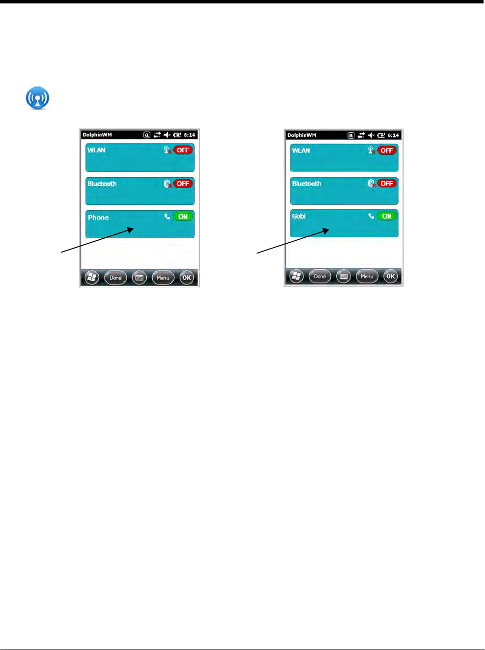
DRAFT COPY 11/11/11
9 - 3
Enabling the WWAN Radio
By default, the WWAN radio is not enabled after a factory reset. Verify the status of the radio in the Dol-
phin Wireless Manager.
Tap on the Home screen to access the Dolphin Wireless Manager.
If the WWAN radio is OFF, tap the rectangle to enable or turn ON the radio.
GSM/HSPA+ Global Radio Dolphin Models
Voice Communication
You can use the Dolphin terminal as a phone over the GSM radio.
Audio Modes
The front panel of the 7800 contains both a speaker and a microphone that you can use to send and
receive audio signals over the GSM network, see Front Panel: 7800 on page 3-5.
There are two audio modes:
• Handset Mode - The front speaker is used for receiving handset voice calls and the front panel
microphone provides audio input to the terminal.
• Hands-Free Mode - Hands-free mode is when you use the rear speaker as a speakerphone. To
switch to speakerphone, tap on the speaker button in the Dialer window, see Accessing the
Dialer Window on page 9-4.
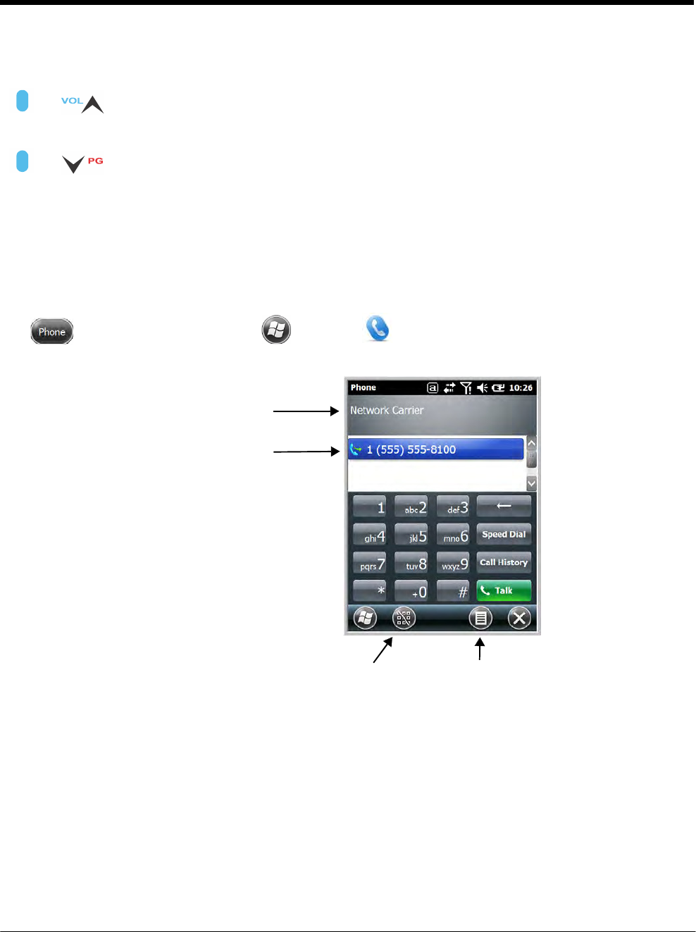
DRAFT COPY 11/11/11
9 - 4
Volume Control
&
Blue
&
Blue
Use the Dolphin keyboard to adjust the volume.
To raise the volume, press the Blue modifier key + up arrow.
To lower the volume, press the Blue modifier key + down arrow.
Or
Press the up or down arrow on the Volume Control button on the left side of the
device to adjust the volume of the active speaker, see Volume Control Button on
page 3-7.
Accessing the Dialer Window
Note: The WWAN radio must be active for voice communication, see Enabling the WWAN Radio on page 9-3.
Tap on the Home screen or tap > Phone to open the Phone dialer.
Displays the network carrier
from the SIM card.
Displays the most
recent calls.
Toggles the touch screen
keypad ON or OFF.
Menu
Dialing
Once the dialer window is open, you can dial out two ways:
• Tap the buttons on the dialer window.
• Use the physical keyboard (when the keyboard is in numeric mode).
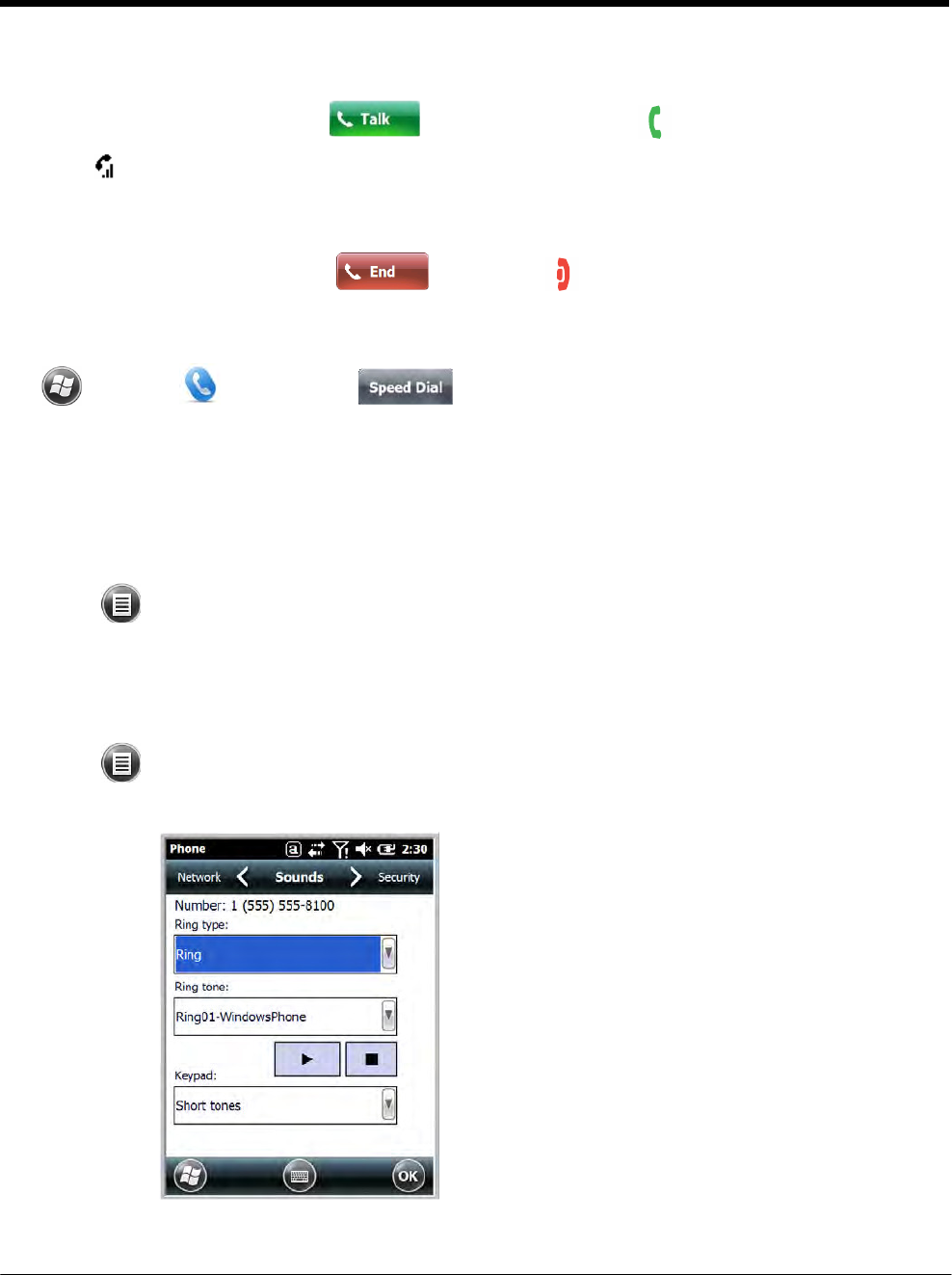
DRAFT COPY 11/11/11
9 - 5
Sending Calls
After the number is dialed, tap Talk or press the Send key .
Note: The icon indicates that the phone is in use.
Ending Calls
While the phone call is live, tap End or End Key .
Accessing Voice Mail
Tap > Phone > Speed Dial > Voice Mail > Call.
Note: Update the voice mail retrieval number by turning the phone OFF and then ON via the Dolphin Wireless
Manager, see Enabling the WWAN Radio on page 9-3.
View Options
From the view menu, you can modify the display screen to show Calls and Contacts, All Calls or Speed
Dial numbers.
Tap Menu > View.
Setup Options
The Options menu contains four setting widows: Sounds, Security, Services, and Network.
Tap Menu > Options.
Sounds
The Sounds screen enables you to customize the:
• Ring type (e.g., Ring, Increasing ring, Ring once,
Vibrate, Vibrate and ring, Vibrate then ring or None)
• Ring tone
• Keypad tone (e.g., Long, Short, or Off)
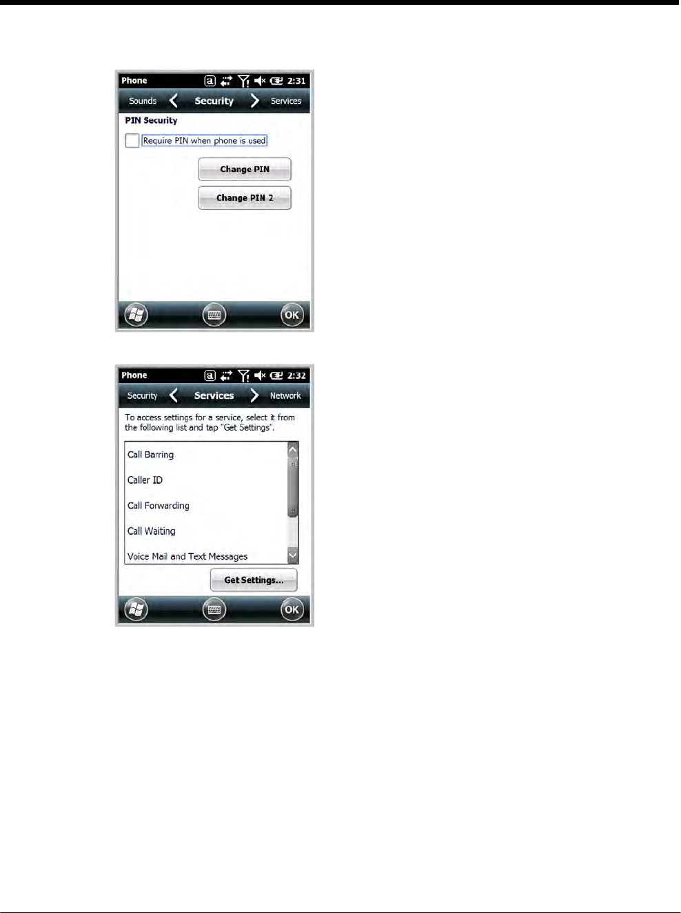
DRAFT COPY 11/11/11
9 - 6
Security
The Security screen provides access to establish or
change your security PIN. Check the box next to,
“Require a PIN when the phone is used” to enable the
PIN security feature.
Services
For each service, the phone reads settings from the
network stored on the SIM card and then displays the
available options from the carrier on the screen. To
customize the settings, select it from the list and tap
“Get Settings”.
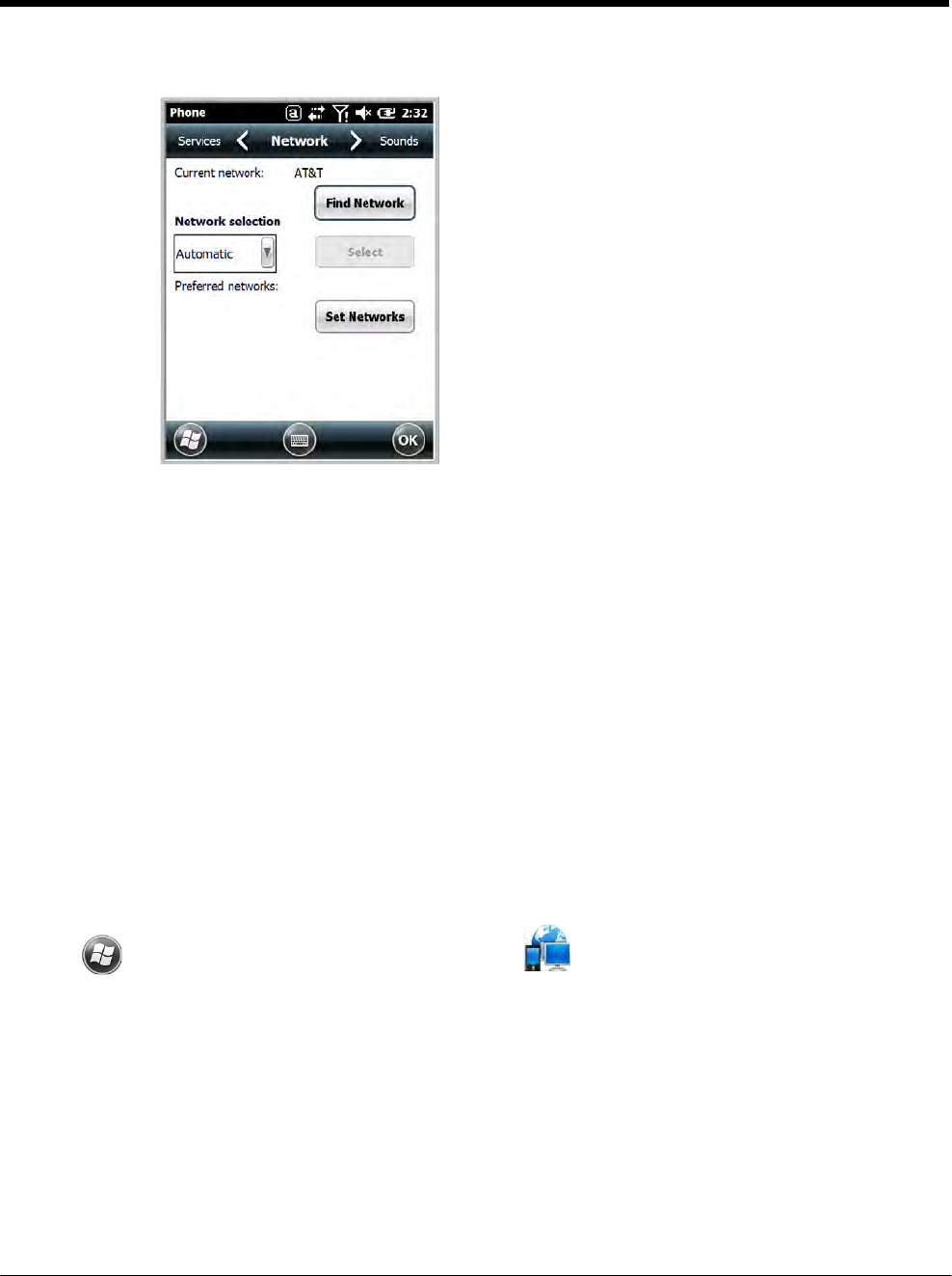
DRAFT COPY 11/11/11
9 - 7
Network
You can find, select, and set your preferred network
order from the Network screen.
Data Communication (GSM/HSPA+ Global Radio Dolphin Models)
You set up data communication via the Connections Manager. The carrier on the SIM card is the ISP.
System Requirements
• The GSM radio must be enabled; see Enabling the WWAN Radio on page 9-3.
• You must have an active SIM card with a DATA plan installed; see Installing a SIM Card and/or Memory
Card on page 3-16.
Information Requirements
You must have from the SIM card carrier:
• The APN (access point name).
• The username and password of the account.
Establishing Data Communication
1. Tap > Settings > Connection > Connections .
2. Under My ISP, tap Add a new modem connection.
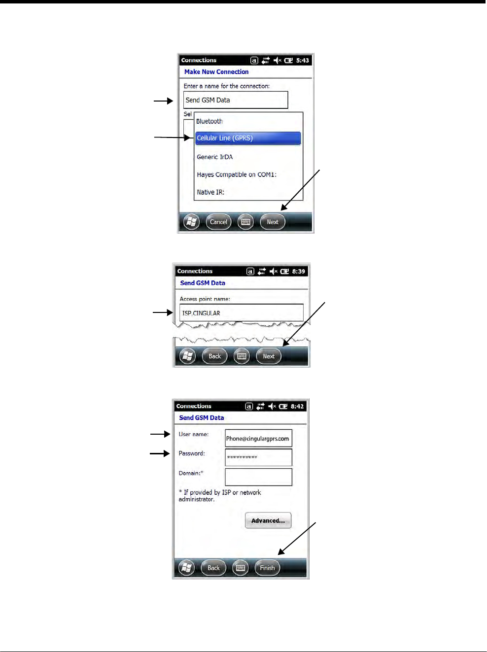
DRAFT COPY 11/11/11
9 - 8
3. Enter a name for the connection. Select Cellular Line (GPRS) as the modem. Tap Next.
4. Enter the Access point name. Tap Next.
5. Enter the username and password from the account. Tap Finish.
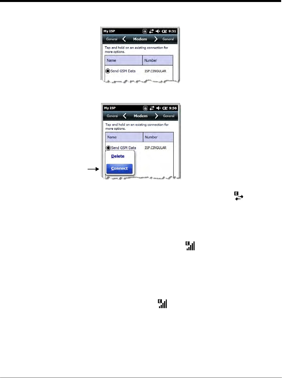
DRAFT COPY 11/11/11
9 - 9
6. The connection you just created should appear in the list on the modem tab.
7. Tap and hold on the connection. Select Connect on the popup menu.
8. The network icon in the Title bar indicates the GSM radio is attempting to connect .
Note: When the device is on a 2G (EDGE/GPRS) network, a data connection failure occurs if the phone is in
use for a voice call while attempting a data connection. Simultaneous voice and data use is only
supported if the device is on a 3G network. In 2G mode, a voice call takes precedence over data
connections. Active data connections are placed in "park" mode automatically and the data is "retrieved"
when the voice call ends.
9. When the connection is complete, the network icon changes to: .
10. You can now send data over GSM.
Ending the Data Connection
By default, the data connection will disconnect after a certain amount of time passes without use.
This period of time is determined by ISP.
To end the data connection manually, tap the network icon in the Title bar and select Disconnect on
the popup bubble.
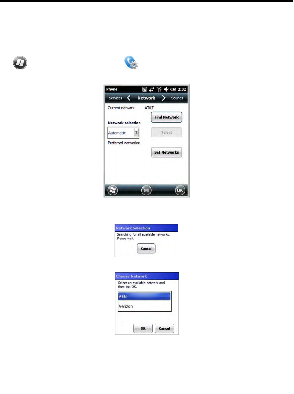
DRAFT COPY 11/11/11
9 - 10
Manual Network Selection
You can select Automatic or Manual network selection. The Phone defaults to Automatic network selec-
tion.
1. When an active SIM card is inserted in the terminal, tap
> Settings > Personal > Phone > Menu > Options.
2. Select the Network tab.
3. Under Network selection, select Automatic (the default selection) or Manual.
a. If you select Manual, the Phone searches for available networks.
b. The found networks appear.
c. Select a new network and tap OK. The Phone registers on the new network and the Network tab
appears.
d. To switch to another network, tap the now active Select button and the process repeats.
4. To switch back to automatic roaming, select Automatic under Select networks and tap OK.
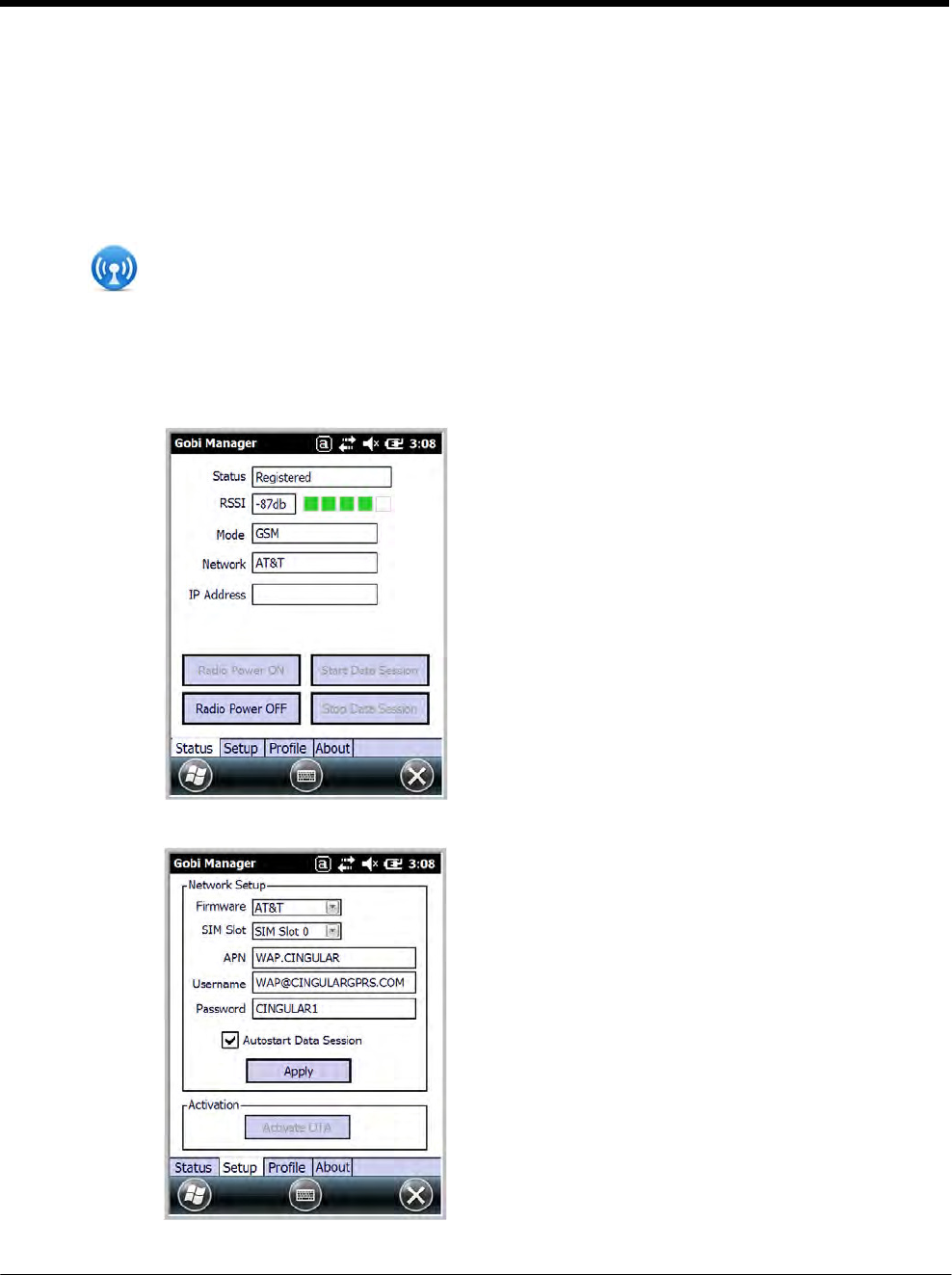
DRAFT COPY 11/11/11
9 - 11
Data Communication GSM/CDMA Dolphin Models
Gobi Manager
The Gobi Manager enables you to see real time status of the radio, setup your Network selection, view
you’re profile and scan for networks. The Gobi Manager contains four tabs: Status, Setup, Profile, and
About.
1. Tap on the Home screen to access the Dolphin Wireless Manager.
2. Tap Menu.
3. Select Gobi Settings.
Status Tab The Status tab contains the real time radio status
information including:
• The power status of the radio (e.g., ON or OFF)
• The received signal strength intensity (RSSI)
• The radio mode used (e.g., GSM, UMTS, EVDO
or 1xRTT)
• The network firmware used
• The IP Address assigned
You can also turn the radio ON or OFF and Start or
Stop a data session from the Status tab.
Setup Tab The Setup tab allows you to view and customize the
Network Setupincluding:
• The Nework Firmware (e.g., AT&T, Verizon,
Sprint, or T-Mobile)
• The SIM Slot accessed
• The Access Point Name (APN)
• The Username of the account
• The Password of the account
• Enable or Disable Automatic Data Sessions
• Activate Over the Air (OTA)
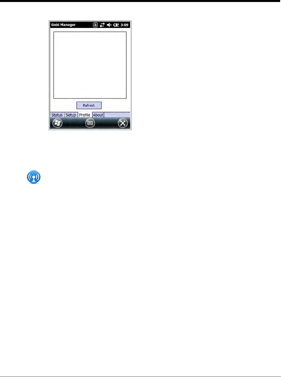
DRAFT COPY 11/11/11
9 - 12
Profile Tab The Profile tab allows you to see Radio capability
information and network statistics including:
• Radio Hardware and Software versions
• Radio and SIM identification numbers
• Serving network connection type and state
• Available radio interfaces for the current serving
network
About Tab Displays copyright and version information for the Gobi Connection Manager.
Establishing Data Communication
1. Tap on the Home screen to access the Dolphin Wireless Manager.
2. Tap Menu and then select Gobi Settings.
3. From the Setup tab, select the carrier and enter user information (GSM only).
Note: An installed SIM card is required and the SIM slot option must be set to 0.
4. Check the Auto Start Data Session checkbox to automatically start the data session.
5. Tap the Apply button. The Connection Manager automatically switches to the Status Tab.
6. Tap the Radio Power ON button.
7. When the radio connects to the network, the status changes to “Registered” and a signal strength is
displayed.
8. If Auto Start Data Session was checked on the Setup tab, the state automatically changes from
“Registered” to “Data Session Open” and an IP address appears. If Auto Start Data Session was
not selected, then the Data session can be started manually by tapping Start Data Session button
from the Status tab.
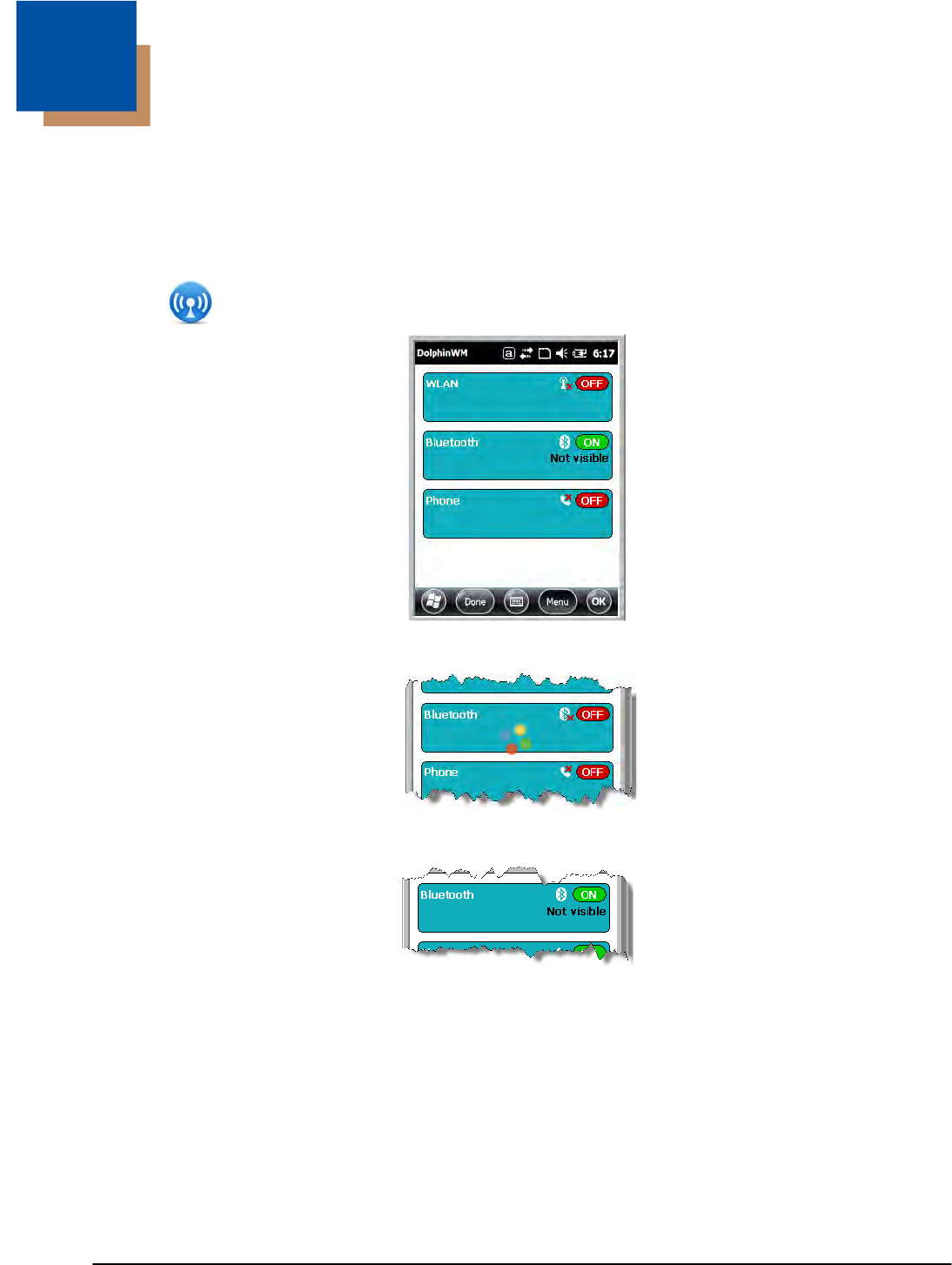
10 - 1
10 DRAFT COPY 11/11/11
Working
with the
Bluetooth
Radio
Enabling the Bluetooth Radio
You enable the Bluetooth radio in the Dolphin Wireless Manager (see page 8-4).
1. Tap on the Home screen to access the Dolphin Wireless Manager.
2. Tap anywhere inside the Bluetooth rectangle and Bluetooth begins activating.
3. When the radio is activated (i.e., transmitting a signal), the OFF button changes to ON.
Now, the Bluetooth radio is transmitting a signal. Additional text in the Bluetooth section tells information
about the Bluetooth radio. “Visible” and “Not visible” indicates whether the Bluetooth radio is discover-
able or not discoverable by other Bluetooth devices.
Now, you can connect to other transmitting and discoverable Bluetooth devices (see page 10-2).
To make the terminal discoverable, see page 10-6.
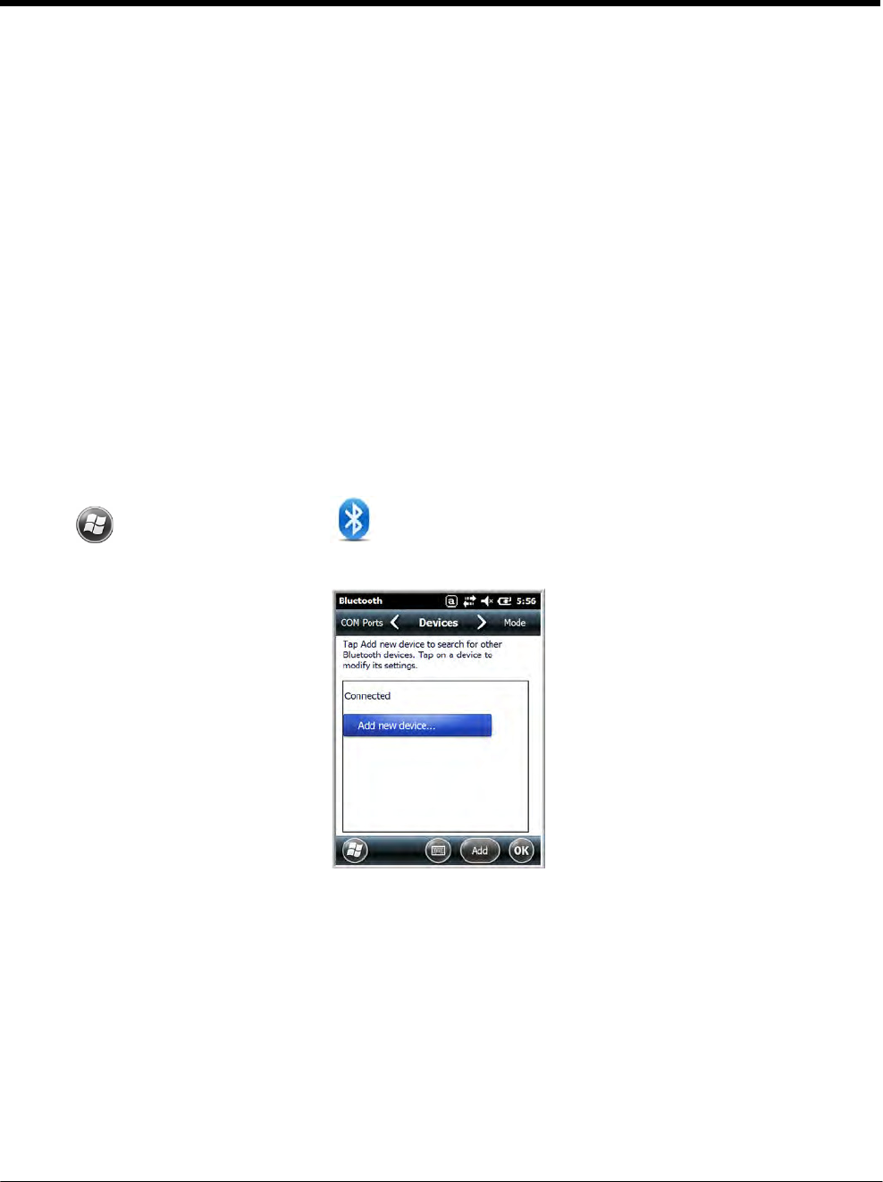
DRAFT
COPY 11/11/11
10 - 2
Pairing and Trusted Devices
The terminal does support pairing. Pairing happens during general connection setup. Paired devices are
"trusted" devices. This means that there is unrestricted access to all services (including services that
require authorization and authentication).
A connection can exclude pairing. A device that is connected to the terminal but not paired with it is con-
sidered an untrusted device. Content can still be passed to untrusted devices by requiring authorization
with each attempt (for example, with the initialization of a file exchange).
Connecting to Other Bluetooth Devices
To connect to other bluetooth devices, you need to perform a device discovery, select a discovered
device, and then connect to the selected device. Pairing happens as part of the connection process.
1. Make sure the bluetooth device is in range and set to be discoverable by other bluetooth devices.
2. In the Dolphin Wireless Manager, tap Menu > Bluetooth Settings.
OR
Tap > Settings > Bluetooth .
3. Tap Add new device. The terminal begins searching for discoverable Bluetooth devices.
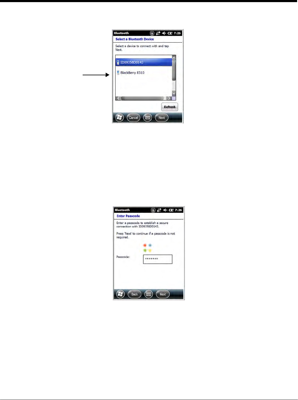
DRAFT
COPY 11/11/11
10 - 3
4. Select a device from the list and tap Next.
The types of devices in the
vicinity of the radio appear in
the list of discovered devices.
5. You are prompted to enter a passcode.
• If the device has a specific passcode, enter it in the Passcode field and tap Next.
When attempting to connect to a printer or headset with Bluetooth capabilities, the passcode may
default to either 1111 or 0000. If there is no default, consult the device literature for the number.
• If the device does not have a specific passcode, you can enter one in the Passcode field and tap
Next to create a passcode.
6. The Bluetooth radio tries to connect with the device.
7. If you created a passcode, you will be prompted by the other device to enter the same passcode.
Enter the created passcode to establish a paired connection.
If you entered a device specific passcode, you should not have to do anything on the other device.
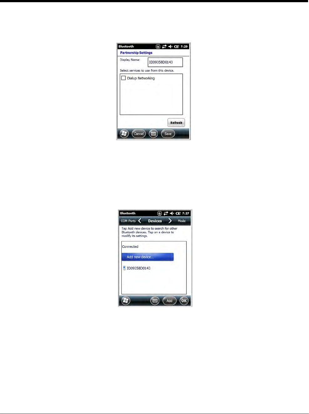
DRAFT
COPY 11/11/11
10 - 4
8. When the connection is complete, a list of matching and supported services on the device appears.
Only the services that are mutually supported on both devices appear in the Partnership Settings
window.
9. Select the services you want to use and tap Save.
The services on the new devices have to be selected or the pairing won’t include those services,
even though the devices are paired. If services are not selected, you will be continually re-prompted
for the passcode from the device.
10. The device appears in the list on the main window.
If you are connecting to a printer or headset, complete any additional steps required by the device.
11. After the passcodes have been accepted on both sides, you have a trusted (paired) connection.
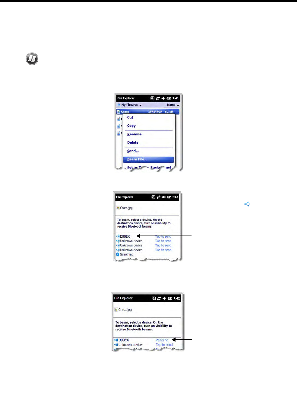
DRAFT
COPY 11/11/11
10 - 5
Transferring Files
Before attempting to transfer files, make sure the receiving Bluetooth device is in range, set to be discov-
erable by other devices, and set to receive incoming beams.
1. Tap > File Explorer.
2. Navigate to the file you want to transfer.
3. Tap and hold on the file and select Beam File on the popup menu.
4. The Bluetooth radio begins searching for devices.
5. Tap the device to begin sending the selected file.
6. While trying to connect, the selected device reads “Pending”.
When a Bluetooth device is first
found, it appears as an
Unknown device; the icon
indicates that the device is a
Bluetooth device.
As data is retrieved, the device
IDs appear in the list.
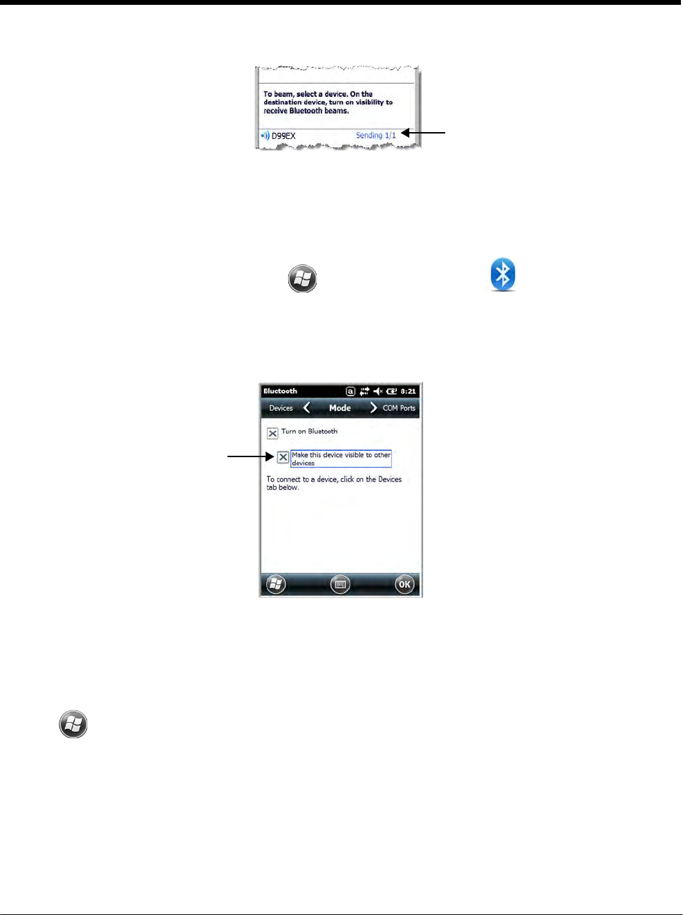
DRAFT
COPY 11/11/11
10 - 6
7. When the file is being transferred, the selected device reads “Sending”.
Making the Terminal Discoverable
By default, the Dolphin terminal is not discoverable, which means that the terminal will not be found by
other Bluetooth devices.
1. To make the terminal discoverable, tap > Settings > Bluetooth .
Note: If you are in the Dolphin Wireless Manager, tap Menu > Bluetooth Settings.
2. Tap Mode on the Horizontal scroll.
3. Select “Make this device visible to other devices” and tap OK.
Enabling the Terminal to Receive Incoming Beams
By default, the 7800 terminal is not configured to receive incoming beams from other devices attemting
file transfers via the Beam File command. Before initiating a file transfer from another device follow the
steps below to enable Beam reception on your Dolphin terminal.
1. Tap > Settings > Connections > Beam.
2. Select “Receive all incoming beams.”
3. Tap OK.

DRAFT
COPY 11/11/11
10 - 7
Selecting COM Ports
You can select COM ports 0-9. For more information, see 7800 COM Port Assignment Table on page 8-
11.

DRAFT
COPY 11/11/11
10 - 8
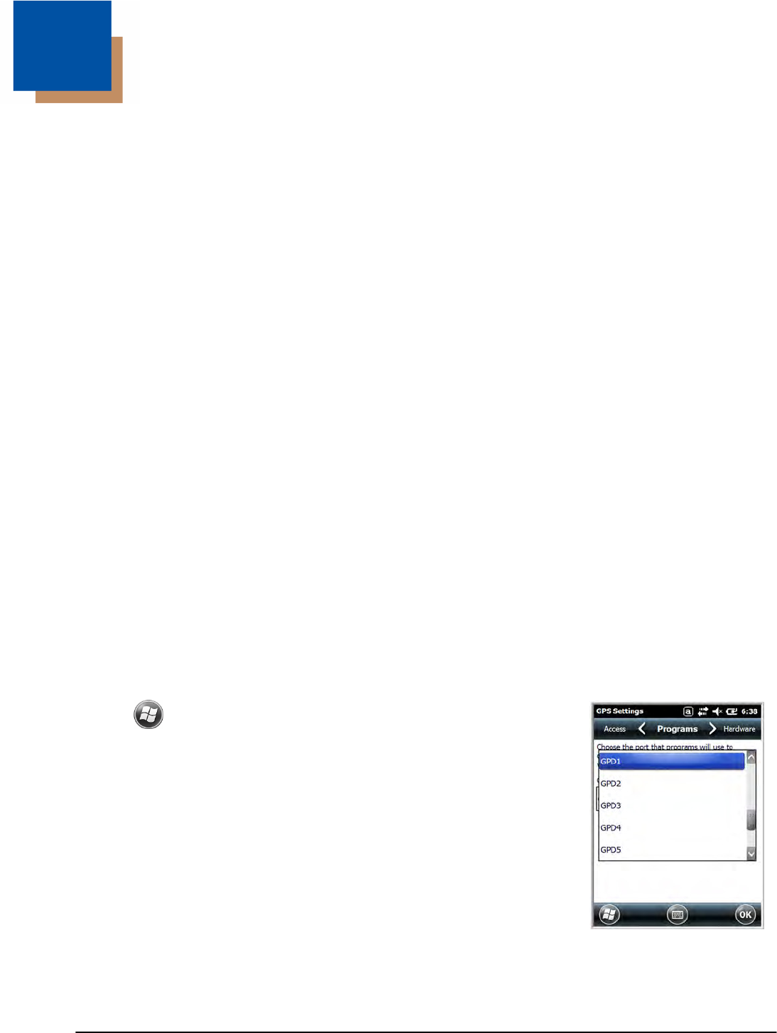
11 - 1
11 DRAFT COPY 11/11/11
Working
with GPS
Overview
The Dolphin 7800 terminal contains an integrated GPS module that allows location tracking of workers
and vehicles, providing better utilization of field assets. Optional mapping and navigation software pro-
vides turn-by-turn driving directions and location information.
Assisted GPS Support
The operating system software does not inhibit nor explicitly support assisted GPS modes, which usually
requires installing a vendor-specific client on the terminal that communicates with the GPS module. This
client would then provide the almanac and/or ephemeris data for warm or hot start modes of operation,
allowing a lower time to first fix (TTFS). The Client must be configured on the terminal, active, and pro-
vide the data to the GPS module through the standard COM port.
Powering the GPS Module
The GPS module powers on automatically when accessed by a software application and powers off
automatically when that software application closes. You cannot manually power on and off the GPS
module.
Communication Ports
There are two ways to access the GPS module: through the actual COM port (COM7) or the GPS Inter-
mediate Driver. The method you use depends on the software application you are using. If the software
application requires the actual COM Port, set the operating system to use COM7. If the software applica-
tion requires the GPS Intermediate Driver, set the operating system to use the GPS Intermediate Driver.
Selecting the Port
1. Tap > Settings > System > External GPS.
2. In the GPS program port: drop-down list, select COM7 or GPD1
(the GPS Intermediate Driver) as required by the application.
Note: The GPS program port and hardware port cannot be the same value.
3. Tap OK to save.
COM7
COM Port 7 can be set to the following baud rates:
• 4800
• 9600 (Default baud rate. Recommended for optimal performance.)
• 19200
• 38400
Other baud rates are not possible. The baud rate selected on COM7 is the actual baud rate with which
the GPS communicates.

11 - 2
DRAFT COPY 11/11/11
GPS Intermediate Driver
When the first user of GPD1 opens the port, the GPS Intermediate Driver opens the COM7 port. The
GPS Intermediate Driver allows multiple applications to open GPD1, and the GPS data is broadcast to
all open ports.
When the GPSID driver is in use, the COM7 port is allocated to GPSID as READ|WRITE (COM7 is still
available for access mode of 0).
For more information about Microsoft’s GPS Intermediate Driver, follow this link:
http://msdn.microsoft.com/en-us/library/ms850332.aspx
GPS Demo
The GPS Demo demonstrates the main functionality of the integrated GPS module. The GPS Demo
uses COM7.
To see the GPS Demo, tap > Demos > GPS Demo.

12 - 1
12 DRAFT COPY 11/11/11
Dolphin
7800
HomeBase Device (Model
7800-HB)
Overview
The Dolphin 7800 HomeBase (Model 7800-HB) is a charging and communication cradle that supports
USB Hi-Speed 2.0v communication, which enables the terminal to interface with the majority of PC-
based enterprise systems. The HomeBase also contains an auxiliary battery well that charges a spare
Honeywell standard or extended battery pack.
The 7800-HB charger is designed for use with battery standard pack models 7800-BTSC or 7800-
BTSCW (Li-ion 3.7 V, 8.9 watt hour) and extended battery pack 7800-BTXC or 7800-BTXCW ( Li-ion 3.7
V, 14.8 watt hour) manufactured for Honeywell International Inc., and with Dolphin 7800 model terminals.
Warning! The HomeBase is not designed for use in hazardous locations.
We recommend use of Honeywell peripherals, power cables, and power adapters. Use of any non-Honeywell
peripherals, cables, or power adapters may cause damage not covered by the warranty.
Unpacking the HomeBase
Open the shipping box and inspect the package to see that the following standard items are included:
• One Dolphin HomeBase, model 7800-HB
• One power supply (see Power on page 12-4)
• One power cord
If any items are missing or anything appears to be damaged, contact your Customer Account Represen-
tative. Keep the original packaging in case you need to return the HomeBase for service or to store the
HomeBase while not in use.
Optional Equipment
A standard USB (Type A to B) cable is required when using the HomeBase for communication between
the terminal and a host device.
Charging Overview
The base provides power to the intelligent battery charging system in all Dolphin terminals that senses
when a full charge has been achieved and switches to a trickle charge to maintain the full charge. The
base completes a full charge of the main battery pack installed in the terminal seated in the terminal well
in 4 hours for the standard battery or 6 hours for the extended battery. The base completes a full charge
of the battery pack in the Auxiliary Battery Well (see page 12-2) in 4 hours for the standard battery or 6
hours for the extended battery.
Note: Before attempting to use, charge, or replace the battery in the terminal, you should read the Guidelines for
Battery Pack Use and Disposal on page 3-13.
Communications
Reliable data communications at speeds of up to 480 Mbps can be transmitted by the base through the
Hi-Speed USB port.
Note: These bases cannot be physically connected to each other - sometimes referred to as “daisy-chained”.
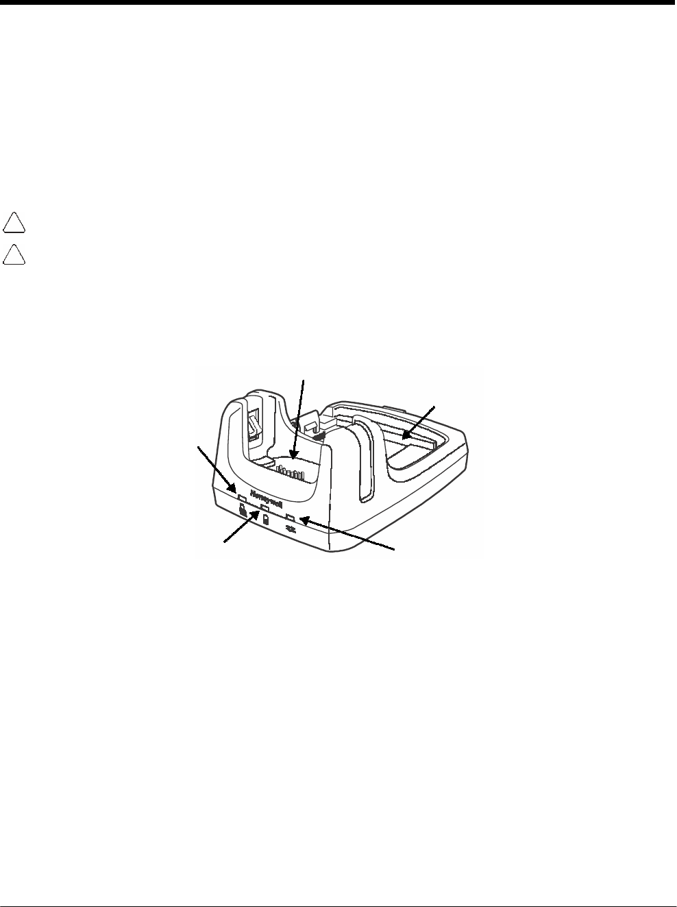
DRAFT COPY 11/11/11
12 - 2
Convenient Storage
The intelligent battery charging system makes this base a safe and convenient storage receptacle for
your Dolphin terminal.
Capacity
The base holds one terminal and features an auxiliary battery well behind the terminal well that can
charge a battery pack independently of the terminal well. This means that one base can charge two bat-
tery packs: the one installed in the terminal and a spare.
We recommend use of Honeywell Li-ion battery packs. Use of any non-Honeywell battery may result in
damage not covered by the warranty.
We recommend use of Honeywell peripherals, power cables, and power adapters. Use of any non-Honeywell
peripherals, cables, or power adapters may cause damage not covered by the warranty.
Parts and Functions
Front Panel
Terminal Well
Auxiliary Battery Well
Power/Dock LED
AUX Battery LED COMM LED
Terminal Well
Place the terminal in this well to communicate with a host device, power the terminal, and
charge the installed battery pack. The base completely charges the main battery in a Dolphin
terminal in 4 hours for the standard battery or 6 hours for the extended battery. If the host
device is a workstation that uses ActiveSync or Windows Device Mobile, synchronization
begins immediately.
Auxiliary Battery Well
See Auxiliary Battery Well on page 12-3.
Power/Dock LED
Indicates if power is supplied to the HomeBase and if a terminal is docked properly in the base.
This color means…
Red The HomeBase has power but no terminal is docked.
Green The HomeBase has power and the terminal is properly seated in the base.
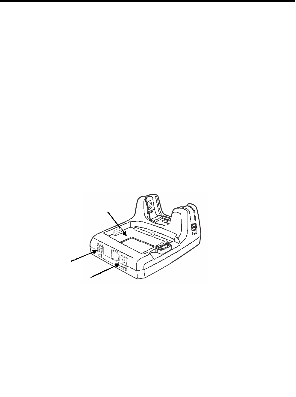
DRAFT COPY 11/11/11
12 - 3
AUX Battery LED
Indicates status of the battery charging in the auxiliary battery well; see Back Panel on page
12-3.
This color means…
Orange The auxiliary battery is charging.
Green The auxiliary battery has completed charging and is ready for use.
Red, Flashing The internal temperature of the auxiliary battery is too hot or there is a battery error.
Charge the auxiliary battery in a cooler environment or replace the battery with a
new Honeywell battery.
For information about charging a battery in the auxiliary battery well, see page 12-5.
COMM LED
This is the communication LED. It indicates the status of data transfer between the Dolphin
terminal and the host device.
This color means…
Green A USB Connection is established with the host workstation.
Back Panel
Auxiliary Battery Well
USB Port
DC Power Jack
Auxiliary Battery Well
The base enables you to charge an additional battery pack independently of the terminal well
in 4 hours for the standard battery or 6 hours for the extended battery. This feature ensures
that you can always have a fully-charged battery for your terminal. See Charging a Spare
Battery in the Auxiliary Battery Well on page 12-5.
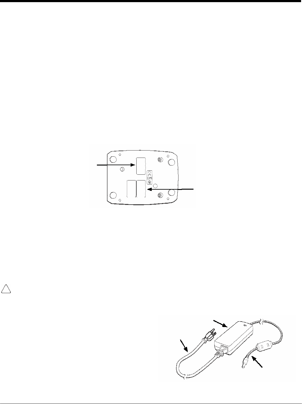
DRAFT COPY 11/11/11
12 - 4
USB Port
This USB port is USB v2.0 Hi-Speed compliant. Using a USB cable, you can connect the base
to a host device, such as a workstation. USB communication occurs through Microsoft
ActiveSync (v4.5 or higher) or Microsoft Windows Mobile Device Center (WMDC) depending
on the host workstation’s operating system. When the terminal is seated in the terminal well, it
is connected to the host device via the base.
Note: ActiveSync on your Dolphin terminal works with Windows Mobile Device Center on host
workstations running Windows Vista or Windows 7 and with ActiveSync on host workstations
running Windows XP. For detailed information on ActiveSync and WMDC visit Microsoft's
Windows Mobile Web site.
DC Power Jack
See Power on page 12-4.
Bottom Panel
For details on how to mount the HomeBase, see Mounting the HomeBase on page 12-7.
Compliance Label
Serial Number Label
Power
The base requires 12 Volts DC input for communications, battery charging, and power output to the ter-
minal; the power adapter included with the base converts the voltage from the AC power source to 12
Volts DC. Use only a UL listed power supply, which has been qualified by Honeywell with output rated at
12VDC and 3 amps with the device. The operating temperature range is -10° to 50°C (14° to 122°F)
Honeywell recommends that you leave the base connected to its power source at all times, so that it is
always ready to use.
We recommend use of Honeywell peripherals, power cables, and power adapters. Use of any non-Honeywell
peripherals, cables, or power adapters may cause damage not covered by the warranty.
Connecting Power to the HomeBase
1. Plug the A/C power cord into the power
adapter.
2. Plug the power cable into the power connector
on the back of the HomeBase.
3. Plug the A/C power cord into a grounded power
source. The base is now powered. The Power/
Dock LED on the HomeBase illuminates solid
red to indicate the HomeBase has power and
no terminal is docked.
Power Adapter
A/C Power Cord
Power Cable
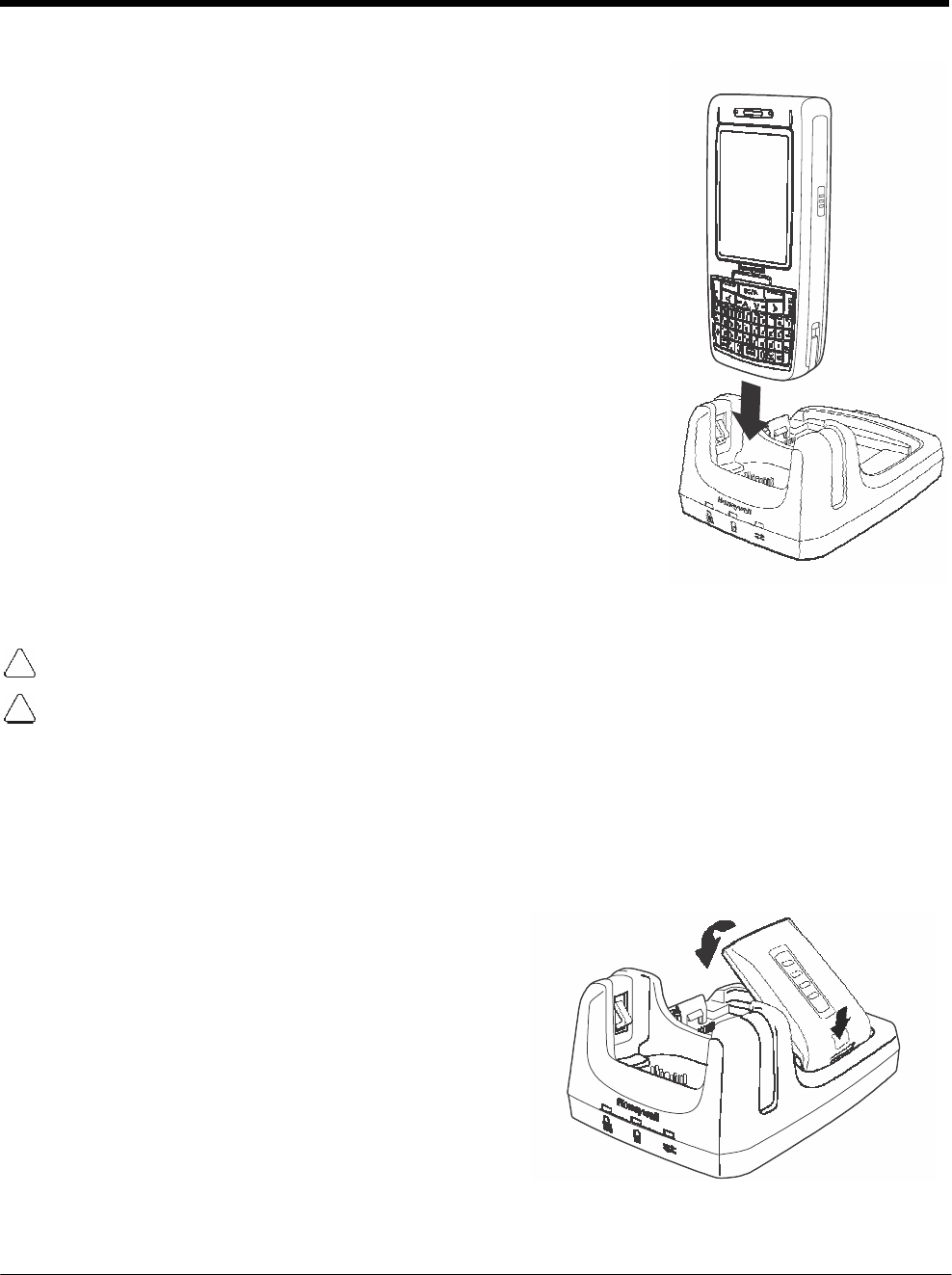
DRAFT COPY 11/11/11
12 - 5
1
Charging the Main Battery
The base provides power to the Dolphin terminal and allows the charg-
ing of the terminal’s main battery. The intelligent battery charging sys-
tem incorporated into all Dolphin terminals prevents overcharging, which
means that Dolphin terminals may be stored in the base indefinitely
without damage to the terminals, battery packs, or the base. The base
completes a full charge of the main battery pack installed in the terminal
seated in the terminal well in 4 hours for the standard battery or 6 hours
for the extended battery.
For more information about Honeywell battery packs and how to check
battery power levels in your terminal, refer to Power (page 7-15) and
Batteries (page 3-12).
To Power a Terminal and Charge its Main Battery
1. Install the battery pack in the terminal; see Install the Main Battery
Pack on page 2-1.
2. Verify the base has power. If the Power/Dock LED is not
illuminated, see Connecting Power to the HomeBase on page 12-4.
3. Slide the terminal into the terminal well. The Power/Dock LED
changes to green. The charging begins immediately if required by
the Dolphin terminal.
Ensure all components are dry prior to mating terminals/batteries with peripheral devices. Mating wet
components may cause damage not covered by the warranty.
We recommend use of Honeywell Li-Ion battery packs. Use of any non-Honeywell battery may result in
damage not covered by the warranty.
Charging a Spare Battery in the Auxiliary Battery Well
The auxiliary battery well located on the back of the base charges a spare battery independently of the
terminal well. The Aux Battery LED on the front panel indicates the status of the battery in this well.
Charge time is 4 hours for the standard battery pack or 6 hours for the extended battery pack; see
Auxiliary Battery Well on page 12-3.
1. Insert the battery at an angle.
Note: Align the battery contacts with the contacts inside 2
the auxiliary battery
well.
2. Snap the battery into place with a hinging motion.
The Aux Battery LED lights orange.
3. Use the AUX Battery LED to monitor the charging
progress. The LED lights green when the auxiliary
battery has completed charging and is ready for
use.
Note: If the AUX Battery LED flashes red, the internal
temperature of the battery is too hot or there is a
battery error. Charge the auxiliary battery in a
cooler environment or replace the battery with a new Honeywell Li-ion battery.

DRAFT COPY 11/11/11
12 - 6
Communication
Dolphin terminals support USB communications out of the box. The base also supports USB communi-
cations via the USB port located on the back. The base acts as a USB device by interfacing the USB sig-
nals of the Dolphin terminal to the USB of the host workstation. Using a standard USB cable, the base’s
USB interface allows the Dolphin terminal to communicate with a workstation.
Requirements
• A base powered by a power cable and power adapter cable
• A standard USB communication cable
• A work station running Windows 98 Second Edition, Windows Me, Windows 2000, Windows NT (4.0
SP6 or higher), Windows XP, Windows Vista, or Windows 7.
• ActiveSync (v4.5 or above) or Widows Mobile Device Center on the workstation
Connecting the Communication Cables
1. Connect power to the HomeBase (see Power on page 12-4).
2. Plug the USB communication cable into the back of the base.
3. Connect the communication cable into the back of the workstation.
4. At this point, the hardware is installed and operating. You may need to reboot your workstation to
complete the installation process.
Establishing Communication
USB communication with the terminal is usually auto-detected and configured by ActiveSync or Win-
dows Mobile Device Center based on the communication cable connected.
Communicating with the Dolphin Terminal
To initiate communications between the Dolphin terminal and peripheral, complete these steps:
1. Insert the Dolphin terminal into the terminal well of the base.
• The DOCK LED illuminates green. If the DOCK LED does not illuminate, make sure that the
terminal is properly seated. You may need to remove and re-insert the terminal.
• The Dolphin terminal activates; if the power is off, the terminal automatically powers on. If the
terminal does not power on, verify that the Honeywell power supply is properly connected to the
cradle and plugged into a functioning outlet.
• If the base is connected to the workstation, the Dolphin terminal automatically opens ActiveSync
or the Windows Mobile Device Center to establish a connection.
2. The base can now transfer data between the terminal and the host device. If communication does
not occur, check the port connections to ensure that the cradle is correctly configured.
Verifying Communication
You can verify that the USB driver is functioning by watching the COMM LED on the USB base. When
the COMM LED illuminates solid green, the base is communicating with the host device.
Note: This base cannot be daisy-chained.
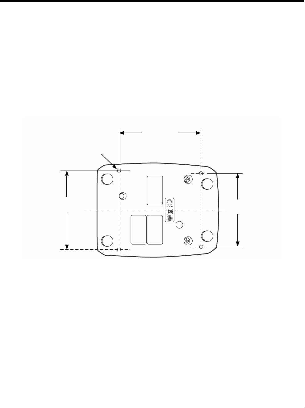
DRAFT COPY 11/11/11
12 - 7
Mounting the HomeBase
Set the base on a dry, stable surface, such as a desktop or workbench near an electrical outlet. Be sure
to provide enough workspace with good lighting for the user to view and operate the Dolphin terminal
while it is in the base. When choosing a mounting location, bear in mind that the location must allow
users' easy access to the Auxiliary Battery Well and the back panel of the HomeBase where the USB
port and the power jack are located.
Optional Hardware Mount
On the bottom of the HomeBase there are four mounting holes with a maximum depth of 7 mm that can
be used to secure the base to a horizontal surface such as a desktop or workbench using M3 self tap-
ping screws.
Optional Mounting Holes for M3
self tapping screws, Qty. 4.
Maximum thread depth of 7 mm.
101 mm
[3.98 in.]
98 mm
[3.86 in.] C
L
90 mm
[3.54 in.]

DRAFT COPY 11/11/11
12 - 8

13 - 1
13 DRAFT COPY 11/11/11
Dolphin
7800
eBase Device (Model
7800-EHB)
Overview
The Ethernet Base (eBase) enables a single Dolphin 7800 computer to communicate with a host device
over an Ethernet network.
The 7800-EHB charger is designed for use with standard battery pack model 7800-BTSC or 7800-
BTSCW (Li-ion 3.7 V, 8.9 watt hour) and extended battery pack model 7800-BTXC or 7800-BTXCW ( Li-
ion 3.7 V, 14.8 watt hour) manufactured for Honeywell International Inc. and with Dolphin 7800 model
terminals.
Warning! The eBase is not designed for use in hazardous locations.
We recommend use of Honeywell peripherals, power cables, and power adapters. Use of any non-Honeywell
peripherals, cables, or power adapters may cause damage not covered by the warranty.
Unpacking the eBase
Open the shipping box and inspect the package to see that the following standard items are included:
• One Dolphin eBase Ethernet cradle, model 7800-EHB
• One power supply (see Power on page 13-4)
• One power cord
You will also need to provide a standard CAT-5 Ethernet network cable. These items are needed to set
up and operate the eBase. If any items are missing or anything appears to be damaged, contact your
Customer Account Representative.
Keep the original packaging in case you need to return the eBase for service or to store the eBase while
not in use.
Charging Overview
The base provides power to the intelligent battery charging system in all Dolphin terminals that senses
when a full charge has been achieved and switches to a trickle charge to maintain the full charge. The
base completes a full charge of the main battery pack installed in the terminal seated in the terminal well
in 4 hours for the standard battery or 6 hours for the extended battery. The base completes a full charge
of the battery pack in the Auxiliary Battery Well (see page 13-2) in 4 hours for the standard battery or 6
hours for the extended battery.
Note: Before attempting to use, charge, or replace the battery in the terminal, you should read the Guidelines for
Battery Pack Use and Disposal on page 3-13.
We recommend use of Honeywell Li-ion battery packs. Use of any non-Honeywell battery may result in
damage not covered by the warranty.
Convenient Storage
The intelligent battery charging system makes this base a safe and convenient storage receptacle for
your Dolphin terminal.
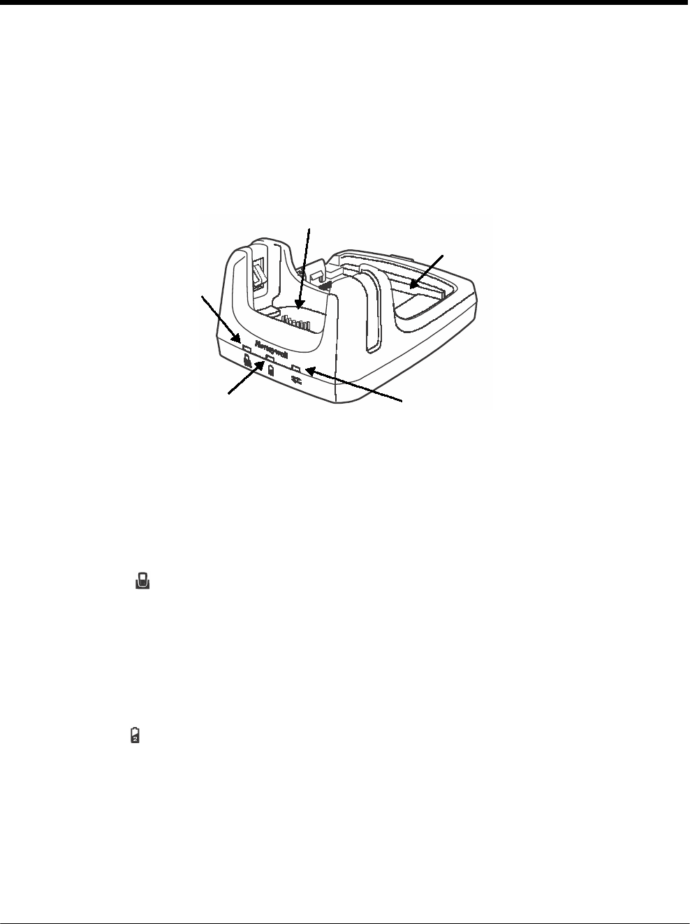
DRAFT COPY 11/11/11
13 - 2
Capacity
The base holds one terminal and features an auxiliary battery well behind the terminal well that can
charge a battery pack independently of the terminal well. This means that one base can charge two bat-
tery packs: the one installed in the terminal and a spare.
Parts and Functions
Front Panel
Terminal Well
Auxiliary Battery Well
Power/Dock LED
AUX Battery LED COMM LED
Terminal Well
Place the terminal in this well to communicate with a host device, power the terminal, and
charge the installed battery pack. The eBase completely charges the main battery in a Dolphin
terminal in 4 hours for the standard battery or 6 hours for the extended battery.
Auxiliary Battery Well
See Auxiliary Battery Well on page 13-3.
Power/DOCK LED
Indicates if power is supplied to the eBase and if a terminal is docked properly in the base.
This color means…
Red The eBase has power but no terminal is docked.
Green The eBase has power and the terminal is properly seated in the base.
AUX Battery LED
The AUX Battery LED indicates the status of the battery charging in the auxiliary battery well;
see Back Panel on page 13-3.
This color means…
Orange The auxiliary battery is charging.
Green The auxiliary battery has completed charging and is ready for use.
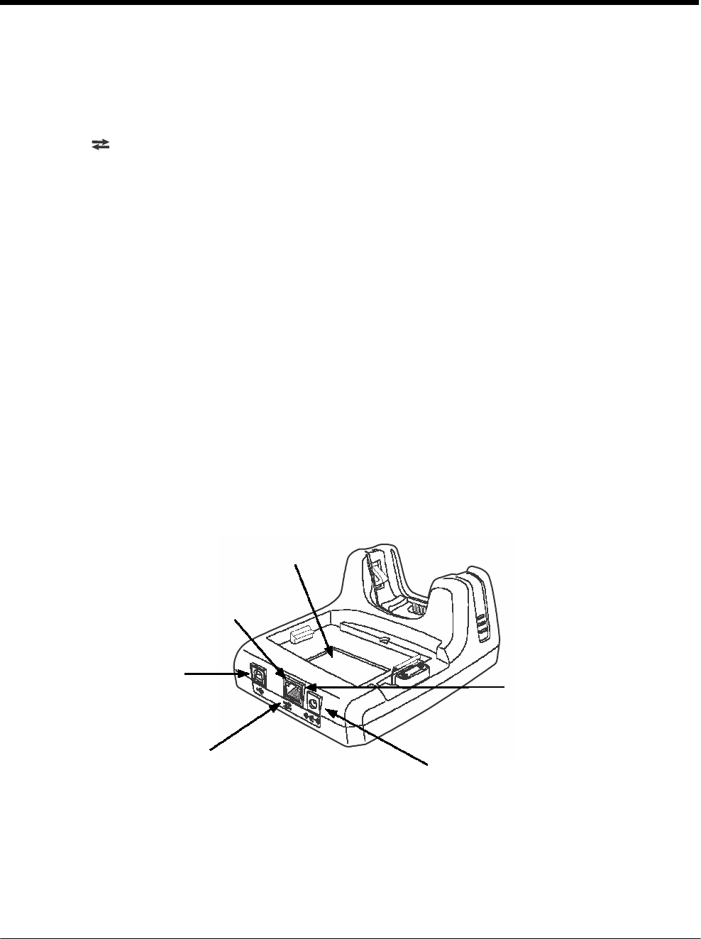
DRAFT COPY 11/11/11
13 - 3
This color means…
Red Flashing The internal temperature of the auxiliary battery is too hot or there is a battery error.
Charge the auxiliary battery in a cooler environment or replace the battery with a
Honeywell battery.
COMM LED
The COMM LED indicates the status of data transfer between the Dolphin terminal and the
eBase.
Ethernet Communication
When the Dolphin terminal is docked:
This color and status means…
Green Solid A connection has been established between the Dolphin terminal
and the Ethernet.
Green Flashing Data transfer in progress.
USB Communication
When the Dolphin terminal is docked:
This color and status means…
Red Solid A USB connection has been established between the Dolphin
terminal and the host workstation.
Back Panel
Auxiliary Battery Well
Green LED
Yellow
LED
RJ45 Ethernet Port
DC Power Jack
Auxiliary Battery Well
The eBase enables you to charge an additional battery pack independently of the terminal well
in 4 hours for the standard battery or 6 hours for the extended battery. This feature ensures
that you can always have a fully charged battery for your terminal.

DRAFT COPY 11/11/11
13 - 4
abel
USB Port
This USB port is USB v2.0 Hi-Speed compliant. Using a USB cable, you can connect the
eBase to a USB compliant device to facilitate USB communication to and from the terminal.
USB communication occurs through Microsoft ActiveSync (v4.5 or higher) or Microsoft
Windows Mobile Device Center depending on the host workstation’s operating system. When
the terminal is seated in the terminal well, it is connected to the peripheral device via the
eBase.
Note: ActiveSync on your Dolphin terminal works with Windows Mobile Device Center on host
workstations running Windows Vista or Windows 7 and with ActiveSync on host workstations
running Windows XP. For detailed information on ActiveSync and Windows Mobile Device
Center visit Microsoft's Windows Mobile Web site.
RJ45 Ethernet Port
Use a standard CAT-5 Ethernet cable; you can connect the ebase to an Ethernet-compliant
device to facilitate Ethernet communication to and from the terminal.
This color and status means…
Green Flashing Data transfer in progress.
Solid A connection has been established between the Dolphin
terminal and the Ethernet.
Yellow Solid Ethernet is connected at 100T.
Off Ethernet is connected at 10T.
DC Power Jack
See Power, below.
Bottom Panel
For details on how to mount the eBase, see Mounting the eBase on page 13-7.
Compliance L
Power
MAC Address Label erial Number Label
The terminal requires 12 Volts DC input for communications and battery charging; the power adapter on
the power cable converts the voltage from the power source to 12 Volts DC. Use only a UL listed power
supply, which has been qualified by Honeywell with output rated at 12VDC and 3 amps with the device.
The operating temperature range is -10° to 50°C (14° to 122°F). Honeywell recommends that you leave
the eBase connected to its power source at all times, so that it is always ready to use.
We recommend use of Honeywell peripherals, power cables, and power adapters. Use of any non-Honeywell
peripherals, cables, or power adapters may cause damage not covered by the warranty.
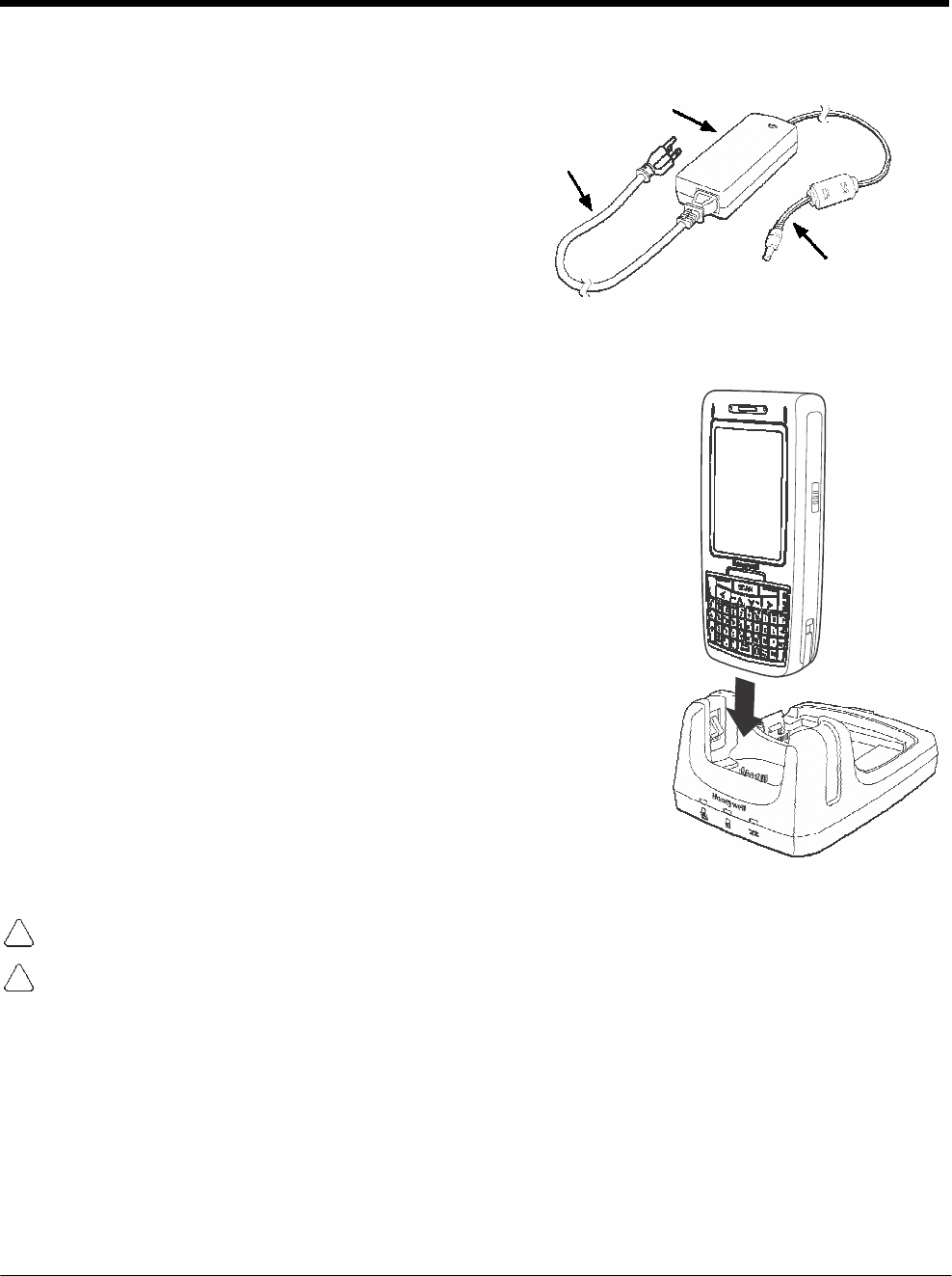
DRAFT COPY 11/11/11
13 - 5
Connecting Power to the eBase
1. Plug the A/C power cord into the power
adapter.
2. Plug the power cable into the power connector
on the back of the eBase.
3. Plug the A/C power cord into a grounded power
source. The Power/Dock LED on the eBase
illuminates solid red to indicate the eBase has
power and no terminal is docked.
Charging the Main Battery
Power Adapter
A/C Power Cord
Power Cable
The base provides power to the Dolphin terminal and allows the charg-
ing of the terminal’s main battery. The intelligent battery charging sys-
tem incorporated into all Dolphin terminals prevents overcharging,
which means that Dolphin terminals may be stored in the base indefi-
nitely without damage to the terminals, battery packs, or the base. The
base completes a full charge of the main battery pack installed in the
terminal seated in the terminal well in 4 hours for the standard battery
or 6 hours for the extended battery.
For more information about Honeywell battery packs and how to check
battery power levels in your terminal, refer to Power (page 7-15) and
Batteries (page 3-12).
To Power a Terminal and Charge its Main Battery
1. Install the battery pack in the terminal; see Install the Main Battery
Pack on page 2-1.
2. Verify the base has power. If the Power/Dock LED is not
illuminated, see Connecting Power to the eBase on page 13-5.
3. Slide the terminal into the terminal well. The Power/Dock LED
changes to green. Battery charging begins immediately if required
by the Dolphin terminal.
Ensure all components are dry prior to mating terminals/batteries with peripheral devices. Mating wet
components may cause damage not covered by the warranty.
We recommend use of Honeywell Li-Ion battery packs. Use of any non-Honeywell battery may result in
damage not covered by the warranty.
Charging a Spare Battery in the Auxiliary Battery Well
The auxiliary battery well located on the back of the base charges a spare battery independently of the
terminal well. The Aux Battery LED on the front panel indicates the status of the battery in this well.
Charge time is 4 hours for the standard battery pack or 6 hours for the extended battery pack; see
Auxiliary Battery Well on page 13-3.
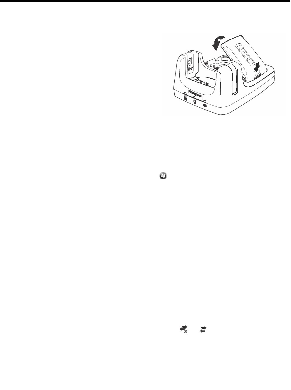
DRAFT COPY 11/11/11
13 - 6
2
1
1. Insert the battery at an angle.
Note: Align the battery contacts with the contacts inside
the auxiliary battery well.
2. Snap the battery into place with a hinging motion.
The Aux Battery LED lights orange.
3. Use the AUX Battery LED to monitor the charging
progress. The LED lights green when the auxiliary
battery has completed charging and is ready for
use.
Note: If the AUX Battery LED flashes red, the internal
temperature of the battery is too hot or there is a
battery error. Charge the auxiliary battery in a
cooler environment or replace the battery with a
new Honeywell Li-ion battery.
Communication
Software Requirements
Before you connect the Dolphin terminal to the eBase, make sure you have the most current software
installed. To check the terminal’s system information, tap > Power Tools > SysInfo.
Applications on the Dolphin Terminal
Applications running on the Dolphin terminal when it is connected to the eBase should be designed spe-
cifically for a partially connected network. For more details, please refer to the Best Practices for Partially
Connected Networks document available at www.honeywellaidc.com.
Establishing Ethernet Communication
Connecting the Dolphin Terminal to the eBase
By default, the Dolphin terminal is configured to obtain IP addresses automatically via DHCP server.
This means that in most cases you would simply plug-and-play the unit.
1. Verify the base has power. If the Power/Dock LED is not illuminated, see Connecting Power to the
eBase on page 13-5.
2. Plug the CAT-5 Ethernet cable into the RJ45 connector on the back of the eBase.
3. Plug the Ethernet cable into the network.
4. Insert the Dolphin into the terminal well. The DOCK LED for the well changes from red to green and
the connection icon on the Dolphin’s title bar changes from
x
to .
Note: Instead of using the default for DHCP assigned IP addresses, the Dolphin terminal can use a statically
assigned IP address. See standard Microsoft Windows Mobile documentation for how to assign a static
IP address to a network adapter. In this case, set a static IP address for the adapter named "SMC95001
USB2.0 FAST Ethernet Drive".

DRAFT COPY 11/11/11
13 - 7
Displaying the eBase and Terminal IP Address
Once the Dolphin terminal has been successfully connected to the eBase, the terminal uses the eBase
IP address. This IP address can be used by any application on the Dolphin terminal.
1. Tap > Power Tools > Network Utilities > IPConfig.
2. Change the Adapter to SMC95001.
3. On the Input tab, tap the Display full configuration button.
4. The Dolphin terminal retrieves and displays the IP configuration for the entire terminal and eBase.
Locate the IpAddress field in the IP configuration list.
Establishing USB Communication
Dolphin terminal’s support USB communication out of the box. The eBase also supports USB communi-
cations using the USB port located on the back panel of the eBase. The eBase acts as a USB device by
interfacing the USB signals of the Dolphin terminal to the USB of the host workstation. Using a standard
USB cable, the ebase’s USB interface allows the Dolphin terminal to communicate with a host worksta-
tion.
Setting Up and Connecting the Dolphin Terminal to the eBase
1. Verify the base has power. If the Power/Dock LED is not illuminated, see Connecting Power to the
eBase on page 13-5.
2. Plug the USB communication cable into the USB port on the back of the eBase.
Note: The Dolphin terminal should always be removed from the eBase when connecting or disconnecting the
USB cable.
3. Connect the other end of the USB cable to the host workstation.
4. Insert the Dolphin terminal in the eBase terminal well. The Power/Dock LED changes to green and
the COMM LED illuminates red.
5. The Dolphin terminal activates and automatically opens ActiveSync to establish a connection.
6. The connection icon in the Dolphin’s navigation bar changes from
x
to it indicate a successful
connection. The eBase can now transfer data between the terminal and the host device.
Mounting the eBase
Set the eBase on a dry, stable surface, such as a desktop or workbench near an electrical outlet. Be sure
to provide enough workspace with good lighting for the user to view and operate the Dolphin terminal
while it is in the eBase.
When choosing a mounting location, bear in mind that the location must allow users' easy access to the
Auxiliary Battery Well and the back panel of the HomeBase where the USB port, Ethernet port, and the
power jack are located.
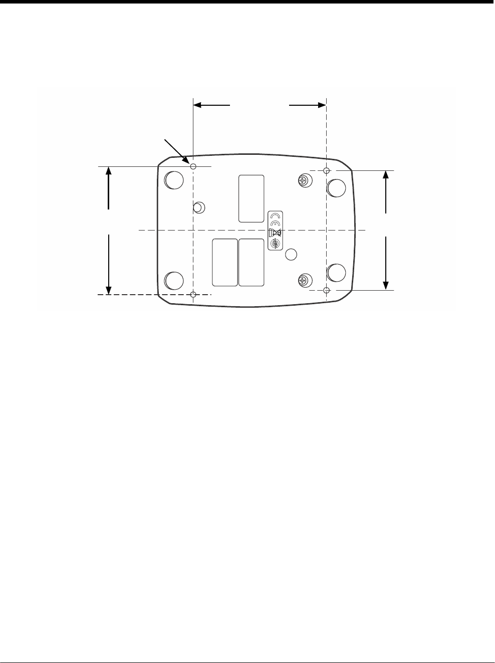
DRAFT COPY 11/11/11
13 - 8
Optional Hardware Mount
On the bottom of the HomeBase there are four mounting holes with a maximum depth of 7 mm that can
be used to secure the base to a horizontal surface such as a desktop or workbench using M3 self tap-
ping screws.
Optional Mounting Holes for M3
self tapping screws, Qty. 4.
Maximum thread depth of 7 mm.
101 mm
[3.98 in.]
98 mm
[3.86 in.] C
L
90 mm
[3.54 in.]

14 - 1
14 DRAFT COPY 11/11/11
Dolphin
7800
Mobile Base Device (Model
7800-MB)
Overview
The Dolphin Mobile Base charging cradle is designed specifically for in-premise and in-transit data col-
lection applications. The base features a mounting bracket and a cigarette lighter adapter to adapt it to
your environment.
The 7800-MB charger is designed for use with Dolphin 7800 model terminals using standard battery
pack model 7800-BTSC or 7800-BTCW ( Li-ion 3.7 V, 8.9 watt hour) or extended battery pack model
7800-BTXC or 7800-BTXCW (Li-ion 3.7 V, 14.8 watt hour) manufactured for Honeywell International Inc.
Warning! The Mobile Base is not designed for use in hazardous locations.
We recommend use of Honeywell peripherals, power cables, and power adapters. Use of any non-Honeywell
peripherals, cables, or power adapters may cause damage not covered by the warranty.
Charging Overview
The base provides power to the intelligent battery charging system in all terminals that senses when a
full charge has been achieved and switches to a trickle charge to maintain the full charge. The base
completes a full charge of the main battery pack in 4 hours for the standard battery pack or 6 hours for
the extended battery pack.
Note: Before attempting to use, charge, or replace the battery in the terminal, you should read the Guidelines for
Battery Pack Use and Disposal on page 3-13.
We recommend use of Honeywell Li-Ion battery packs. Use of any non-Honeywell battery may result in
damage not covered by the warranty.
Convenient Storage
Intelligent battery charging makes the base a safe and convenient storage receptacle for your Dolphin
terminal.
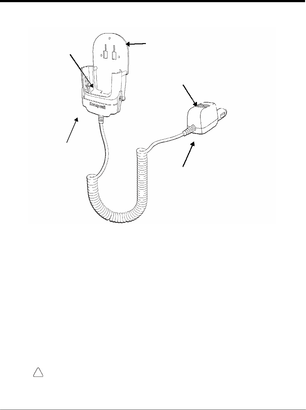
DRAFT COPY 11/11/11
14 - 2
Mobile Base Components
Terminal Well Mounting Back Plate
Power
Adapter
Terminal Locking
Lever
Adapter Power LED
(not in view)
Mounting Back Plate
Used to mount the base to a fixed location.
Terminal Locking Lever
The mobile base has a locking lever on the front. When the lever is in the down position the
terminal in locked in the base. To unlock the terminal push the lever up.
Terminal Well
Place the terminal in this well to charge the main battery pack.
Power Adapter
The mobile charger is equipped with a car adapter cable that can be connected to a vehicle
cigarette lighter outlet.
UL listed power supply
Input: 9V-24VDC, 3.2A
Output: 5VDC 3000mA
Verify that the power source is always within the specified range and observe correct
input voltage polarity. An improper input voltage range or reverse polarity could damage
the power conversion circuitry.
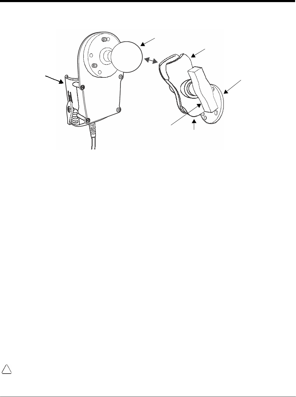
DRAFT COPY 11/11/11
14 - 3
Back Panel and Mounting Brackets
Ball
Joint
Pivot
Bracke
t
Base
Mounting Bracket
Turnscrew
Ball Joint
Ball Joints
There are two ball joints: one that is attached to back of the base and one on the mounting
bracket. Both ball joints are inserted into the bracket and secured to mount the base.
Pivot Bracket
The bracket contains the turnscrew and two slots. Ball joints are inserted into each slot and
secured with the turnscrew.
Turnscrew
The turnscrew is located on the side of the pivot bracket. Rotate the turnscrew to secure or
loosen the ball joint slots.
Mounting Bracket
The mounting bracket is what you attach to the mounting surface. It is comprised of a ball joint
and flat disk. The disk contains drill holes you use to secure the base to the mounting surface.
Mounting
The adjustable mounting bracket holds the terminal securely in place and gives the user a variety of
options for mounting the base.
Safety Precautions
Honeywell is not responsible for any damages caused to you, your vehicle, or other individuals due to the
installation of the Dolphin Mobile mount.
Follow these safety precautions when mounting the mobile base:
Never drill into a surface in your vehicle without first consulting a mobile installation professional
experienced with your vehicle type to avoid damaging the vehicle's safety features, gas tank, elec-
trical system or other sensitive vehicle components.
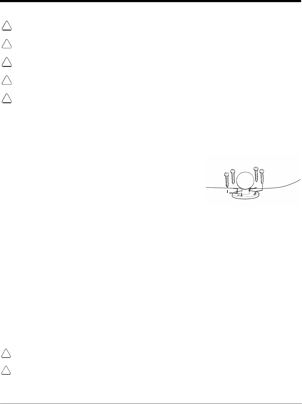
DRAFT COPY 11/11/11
14 - 4
Do not install the Mobile base in an air bag deployment zone. Honeywell assumes no responsibility
of liability for injury or death because of car crashes and/or air bag deployment.
Do not mount the base in a location where it prevents safe operation of the vehicle and/or impedes
the vehicle operator's field of view.
Do not mount the base in a location where the connectors on the bottom panel of the base are not
easily accessible. Be sure to leave enough room for unrestricted cable connections.
The Mobile base is intended for use in an enclosed space protected from the elements. Do not
mount the Mobile base on external vehicle surfaces.
Select a mounting surface that is flat and smooth like the console area in the vehicle located
between the seats.
Installation
Mounting hardware is not included. You must provide the appropriate hardware for your particular appli-
cation and vehicle type. To ensure a safe installation, consult a mobile installation professional
experienced with your vehicle type.
1. Using the bracket as a template, mark the locations for the mount-
ing screws.
2. Drill the appropriate size pilot holes in the mounting surface.
3. Secure the mounting bracket to the mounting surface using the
appropriate screw type for your application and vehicle type.
4. Loosen the turnscrew.
5. Insert the ball joint of the mounting bracket to the back of the bracket.
6. Insert the ball joint on the back of the base into the other side of the bracket.
7. Tighten the turnscrew to secure both ball joints.
Charging the Main Battery
The mobile base provides power to the Dolphin and allows charging of the main batteries in the terminal.
The main battery charges in 4 hours for the standard battery or 6 hours for the extended battery. The
intelligent battery charging system incorporated into all Dolphin terminals prevents overcharging, which
means that terminal may be seated in the base indefinitely without damage to the terminal, battery pack,
or the base.
For more information about Honeywell battery packs and how to check battery power levels in your ter-
minal, refer to Power (page 7-15) and Batteries (page 3-12).
To Power a Terminal and Charge its Main Battery
Ensure all components are dry prior to mating terminals/batteries with peripheral devices. Mating wet compo-
nents may cause damage not covered by the warranty.
We recommend use of Honeywell Li-Ion battery packs. Use of any non-Honeywell battery may result in dam-
age not covered by the warranty.
1. Install the main battery pack in the terminal; see Install the Main Battery Pack on page 2-1.
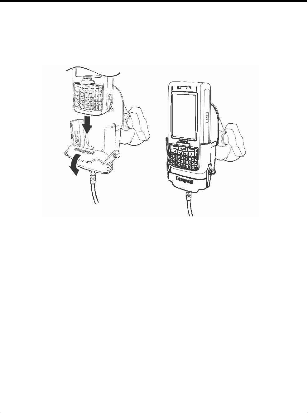
DRAFT COPY 11/11/11
14 - 5
2. Plug the power adapter into the vehicle power outlet (e.g., cigarette lighter outlet).
3. Lift the base locking latch up.
4. Slide the Dolphin into the terminal well and lower the locking latch. Charging begins immediately if
required by the Dolphin terminal.

DRAFT COPY 11/11/11
14 - 6

15 - 1
15 DRAFT COPY 11/11/11
Dolphin
7800
ChargeBase Device (Model
7800-CB)
Overview
The 7800 ChargeBase is a 4-slot charging cradle that can power 4 Dolphin terminals, and charge their
main batteries in 4 hours for the standard battery or 6 hours for the extended battery.
The 7800-CB charger is designed for use with Dolphin 7800 model terminals using one of the following
battery pack models: standard battery pack model 7800-BTSC (Li-ion 3.7 V, 8.9 watt hour), extended
battery pack model 7800-BTXC, or extended pack model 7800BTXCW (Li-ion 3.7 V, 14.8 watt hour)
manufactured for Honeywell International Inc.
Warning! The ChargeBase is not designed for use in hazardous locations.
We recommend use of Honeywell peripherals, power cables, and power adapters. Use of any
non-Honeywell peripherals, cables, or power adapters may cause damage not covered by the warranty.
Unpacking the ChargeBase
Open the shipping box and inspect the package to see that the following standard items are included:
• One Dolphin ChargeBase, model 7800-CB
• One power supply (see Power on page 15-3)
• One power cord
These items are needed to operate the ChargeBase. If any items are missing or anything appears to be
damaged, contact your Customer Account Representative. Keep the original packaging in case you
need to return the ChargeBase for service or to store the ChargeBase while not in use.
Charging Overview
The base supplies power to the intelligent battery charging system in all Dolphin terminals, which senses
when a full charge has been achieved and switches to a trickle charge to maintain the full charge.
As battery packs charge, the charging circuitry follows the two-step charging process (CC-CV) that is
recommended for the battery type. The process monitors changes in temperature, current, and voltage.
The main battery of each terminal charges in 4 hours for the standard battery or 6 hours for the extended
battery.
Note: Before attempting to use, charge, or replace the battery in the terminal, you should read the Guidelines for
Battery Pack Use and Disposal on page 3-13.
Convenient Storage
Intelligent battery charging makes this base a safe and convenient storage receptacle for your Dolphin
terminal.
Capacity
The base can hold up to 4 Dolphin terminals. Each charging well charges each terminal independently of
the other wells.
We recommend use of Honeywell Li-Ion battery pack. Use of any non-Honeywell battery may result in damage
not covered by the warranty.
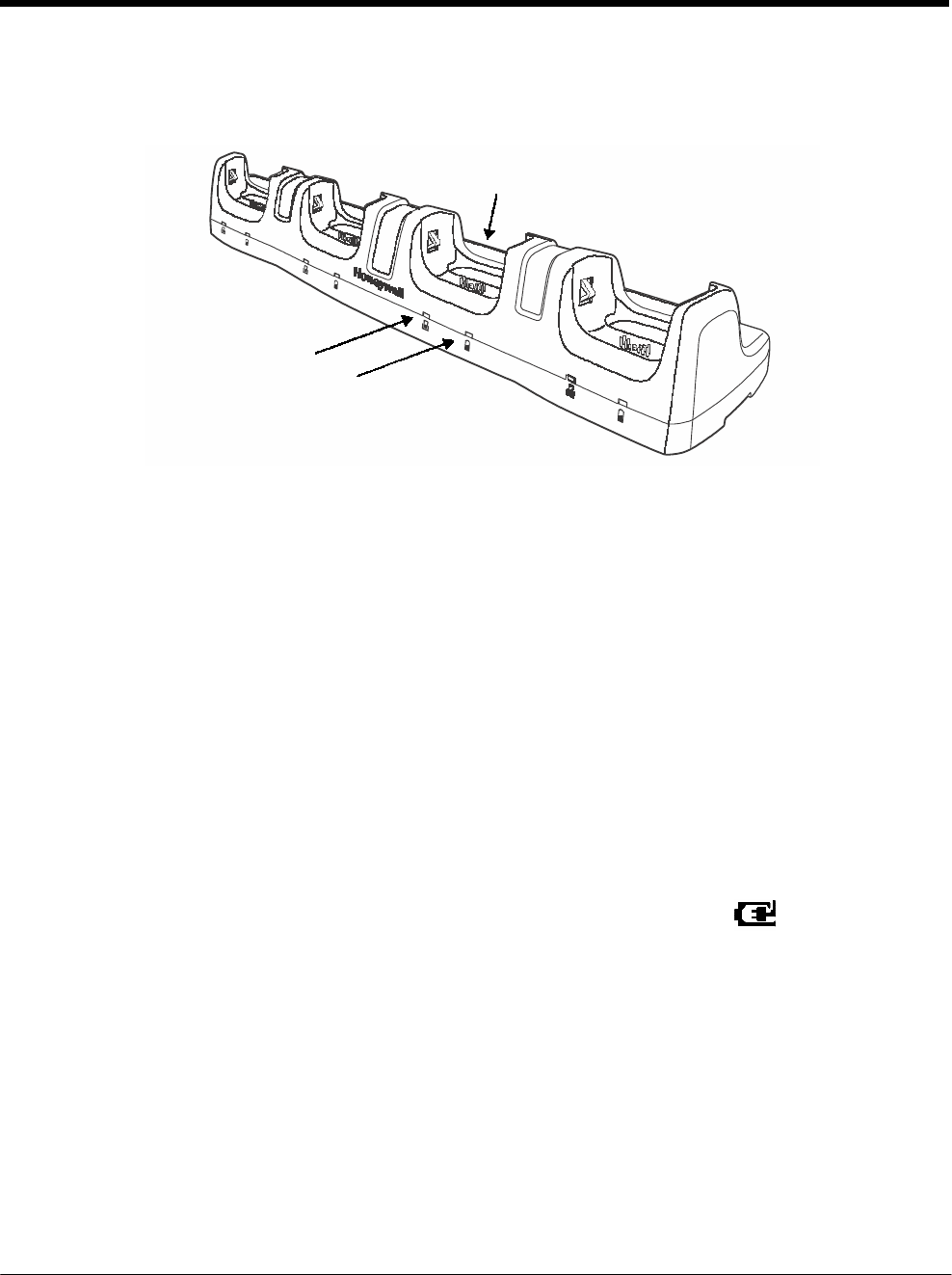
DRAFT COPY 11/11/11
15 - 2
Parts and Functions
Front Panel
Terminal Wells (Qty. 4)
Power/Dock LED (Qty. 4)
Charge LED (Qty. 4)
Terminal Wells
The base contains four terminal wells. Each well has its own dedicated Power/Docking LED
and Charging LED indicator.
Power/Dock LEDs
The Power/Dock LED indicates if the ChargeBase has power and if the terminal is properly
seated in the terminal well. Each terminal well has its own dedicated Power/Dock LED.
This color means…
Red The ChargeBase has power but no terminal is docked.
Green The ChargeBase has power and the terminal is properly seated in the well facilitating
communication between the base and terminal
Charge LEDs
Each terminal well has a dedicated Charge LED located on the front of the base. When a
Dolphin is docked in a terminal well, the Charge LED illuminates green to indicate power is
being applied to the Dolphin. The Battery Icon in the Dolphin window indicates the
terminal is running on external power. If a battery pack is installed, the battery is charging in
the background.
When the Dolphin is removed from the base, the battery icon indicates the charge level of the
main battery pack, see Icons in the Title Bar on page 2-5. For additional information on how to
check the power levels of the main battery pack and the backup battery, while the terminal is
docked, see Checking Battery Power on page 3-15.
For details on how to charge the terminal using the ChargeBase, see Charging the Main
Battery on page 15-4.
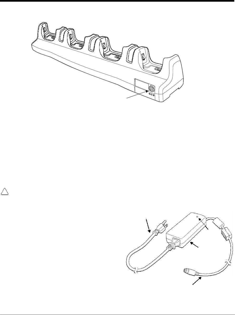
DRAFT COPY 11/11/11
15 - 3
Back Panel
Power Supply
Connector
Power Supply Connector
This connector receives input from the power adapter. Plug the power connector cable from
the power adapter into this connector.
Power
The terminal requires 12 Volts DC input for battery charging; the power adapter on the power cable con-
verts the voltage from the power source to 12 volts DC. Use only a UL Listed power supply, which has
been qualified by Honeywell with output rated at 12VDC and 8.5 amps with the device. The operating
temperature range is -10° to 45°C (14° to 113°F).
Honeywell recommends that you leave the ChargeBase connected to its power source at all times, so
that it is always ready to use.
We recommend use of Honeywell peripherals, power cables, and power adapters. Use of any non-Honeywell
peripherals, cables, or power adapters may cause damage not covered by the warranty.
Connecting Power to the ChargeBase
1. Plug the A/C power cord into the power adapter.
2. Plug the power connector cable into the power
connector on the back panel of the ChargeBase.
3. Plug the A/C power cord into a standard wall
outlet. The LED on the Power Adapter
illuminates to indicate power.
4. All of the Power/Dock LEDs illuminate red to
indicate the base has power. Terminal wells with
properly docked Dolphins indicate power with a
green LED.
5. The base is ready to begin charging terminals.
A/C Power Cord
Power Connector Cable
LED
Power Adapter
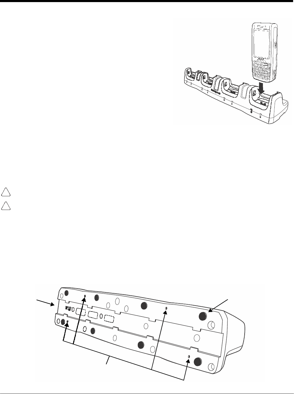
DRAFT COPY 11/11/11
15 - 4
Charging the Main Battery
The base provides power to the Dolphin terminal(s) and
allows charging of the main batteries in the terminals. The
main battery of each terminal charges in 4 hours for the
standard battery or 6 hours for the extended battery. The
intelligent battery charging system incorporated into all
Dolphin terminals prevents overcharging, which means that
Dolphin terminals may be seated in the base indefinitely
without damage to the terminals, battery packs, or the base.
For more information about Honeywell battery packs and
how to check battery power levels in your terminal, refer to
Power (page 7-15) and Batteries (page 3-12).
To Power a Terminal and Charge its Main Battery
1. Install the main battery pack in the terminal; see Install the Main Battery Pack on page 2-1.
2. Verify the base has power. If the Power/Dock LEDs are not illuminated, see Connecting Power to
the ChargeBase on page 15-3.
3. Slide the Dolphin terminal into one of the four terminal wells. The Power/Dock LED for the well
changes to green. Charging begins immediately if required by the Dolphin terminal.
Ensure all components are dry prior to mating terminals/batteries with peripheral devices. Mating wet
components may cause damage not covered by the warranty.
We recommend use of Honeywell Li-Ion battery packs. Use of any non-Honeywell battery may result in
damage not covered by the warranty.
Mounting the ChargeBase
This base should be mounted to a dry, stable surface. When choosing a location, always bear in mind
that:
• The mounting location must allow users easy access to the power connector.
• The base should be oriented so that users can easily see the LEDs.
Bottom Panel
DIN Rail Slot Rubber Feet, Qty. 8
Mounting Holes for Wall
Mount Bracket Hardware,
Qty. 4
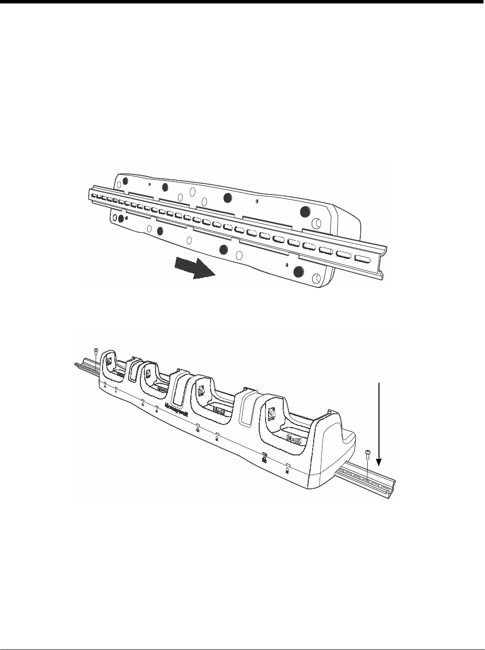
DRAFT COPY 11/11/11
15 - 5
Desk Mounting
The DIN Rail (7.5 X 35 mm) slot on the bottom panel enables secure mounting on a horizontal surface.
Hardware Required
• 3/16 in. dia x 5/8 in. long pan head screw
• 1/2 in. OD x 7/32 in. ID x 3/64 in. thick
• 3/16 in. dia nut
Installing the DIN Rail
1. Slide the DIN Rail into the DIN Rail slot on the bottom panel of the base.
2. Turn the base and DIN Rail right side up.
3. Then, using the appropriate nuts and bolts, secure the DIN Rail to a stable, flat horizontal surface.
DIN Rail (7.5 X 35 mm)

DRAFT COPY 11/11/11
15 - 6

16 - 1
16 DRAFT COPY 11/11/11
Dolphin
7800 Net
Base Device (Model
7800-NB)
Overview
The Net Base enables up to four Dolphin 7800 mobile computers to communicate with a host device
over an Ethernet network. In addition, the Net Base provides a second RJ45 Ethernet port for connec-
tion to an additional device such as a printer, workstation, eBase, or another Net Base.
The 7800-NB charger is designed for use with Dolphin 7800 model terminals using standard battery
pack model 7800-BTSC (Li-ion 3.7 V, 8.9 watt hour) or extended battery pack model 7800-BTXC (Li-ion
3.7 V, 14.8 watt hour), manufactured for Honeywell International Inc.
Warning! The Net Base is not designed for use in hazardous locations.
We recommend use of Honeywell peripherals, power cables, and power adapters. Use of any non-Honeywell
peripherals, cables, or power adapters may cause damage not covered by the warranty.
Unpacking the Net Base
Open the shipping box and inspect the package to see that the following standard items are included:
• One Dolphin Net Base Ethernet cradle, model 7800-NB
• One power supply (see Power on page 16-4)
• One power cord
You will also need to provide a standard CAT-5 Ethernet network cable. These items are needed to set
up and operate the Net Base. If any items are missing or anything appears to be damaged, contact your
Customer Account Representative.
Keep the original packaging in case you need to return the Net Base for service or to store the Net Base
while not in use.
Charging Overview
The base supplies power to the intelligent battery charging system in all Dolphin terminals, which senses
when a full charge has been achieved and switches to a trickle charge to maintain the full charge.
As battery packs charge, the charging circuitry follows the two-step charging process (CC-CV) that is
recommended for the battery type. The process monitors changes in temperature, current, and voltage.
The main battery of each terminal charges in 4 hours for the standard battery or 6 hours for the extended
battery.
Convenient Storage
Intelligent battery charging makes this base a safe and convenient storage receptacle for your Dolphin
terminal.
Capacity
The base can hold up to 4 Dolphin terminals. Each charging well charges each terminal independently of
the other wells.
We recommend use of Honeywell Li-ion battery packs. Use of any non-Honeywell battery may result in
damage not covered by the warranty.
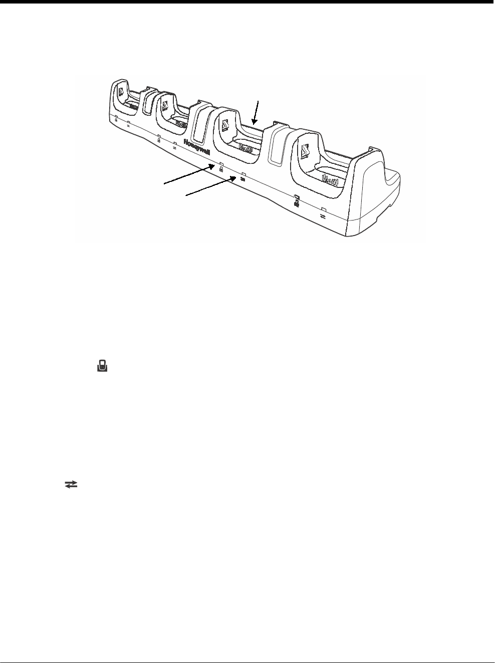
DRAFT COPY 11/11/11
16 - 2
Parts and Functions
Front Panel
Terminal Wells (Qty. 4)
Power/Dock LED (Qty. 4)
COMM LED (Qty. 4)
Terminal Wells
The Net Base contains four terminal wells. Each well has its own dedicated Power/Dock LED
and COMM LED indicator.
Place the Dolphin terminal in any one of the four wells to communicate with a host device,
power the terminal, and charge the installed battery pack. The Net Base completely charges
the main battery in a Dolphin terminal in 4 hours for the standard battery or 6 hours for the
extended battery.
Power/DOCK LED
Indicates if power is supplied to the Net Base and if a terminal is docked properly in the terminal
well. Each terminal well has its own dedicated Dock LED.
This color means…
Red The Net Base has power but no terminal is docked.
Green The Net Base has power and the terminal is properly seated in the base.
COMM LED
The COMM LED indicates the status of connection and data transfer between the Dolphin
terminal and the Net Base. Each terminal well has its own dedicated COMM LED.
When the Dolphin terminal is docked:
This color and status means…
Green
Solid
A
connection
has
been
esta
b
lished
bet
w
een
the
Dolphin
te
r
minal
and the Net Base.
Green Flashing Data transfer in progress.
Note: The COMM LED does not necessrily indicate the Net Base and terminal are connected to a valid Ethernet
link. For more information, see RJ45 Ethernet Ports on page 16-3.
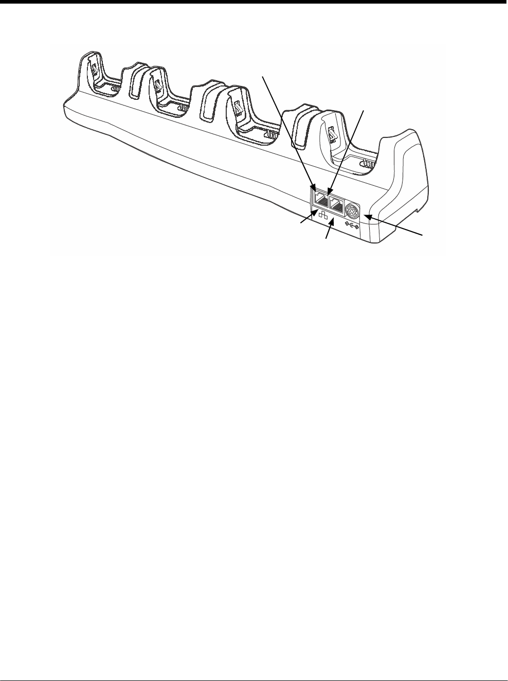
DRAFT COPY 11/11/11
16 - 3
Back Panel
Green LED (Qty. 1 Per Port)
Yellow LED (Qty. 1 Per
Por
t
)
Port 1: 10/100Mbps RJ45 Ethernet Port
Port 2: 100Mbps Only RJ45 Ethernet Port
DC Power Jack
DC Power Jack
This connector receives input from the power adapter. Plug the power connector cable from
the power adapter into this connector, see Power on page 16-4.
RJ45 Ethernet Ports
The Net Base contains two RJ45 Ethernet ports. You can connect the Net Base to an Ethernet-
compliant device to facilitate Ethernet communication to and from the terminal by plugging a
standard CAT-5 Ethernet cable into one of the two Ethernet ports provided. The second RJ45
Ethernet port can be used for connection to an additional device such as a printer, workstation,
eBase, or another Net Base.
Note: The Net Base does not use a Spanning Tree Protocol (STP). When both RJ45 Ethernet ports
are used, do not connect both Net Base interfaces to the same layer 2 LAN.
Note: Ethernet Port 2 only supports 100Mbps Ethernet connections. Plugging in a 10Mbps connection
into Port 2 may cause other ports to stop working. For 10Mbps connections use Ethernet Port 1.
Each Ethernet port has a dedicated green and yellow status LED.
This color and status means…
Green Flashing Data transfer is in progress.
Solid A connection has been established between the Net Base and
the Ethernet.
Yellow Solid Ethernet is connected at 100T.
Off Ethernet is connected at 10T.
Note: The terminal and Ethernet link must be set up properly to allow the terminal to communicate to other devices
and/or the Internet. For more information, see Connecting the Dolphin Terminal to the Net Base on page 16-6.
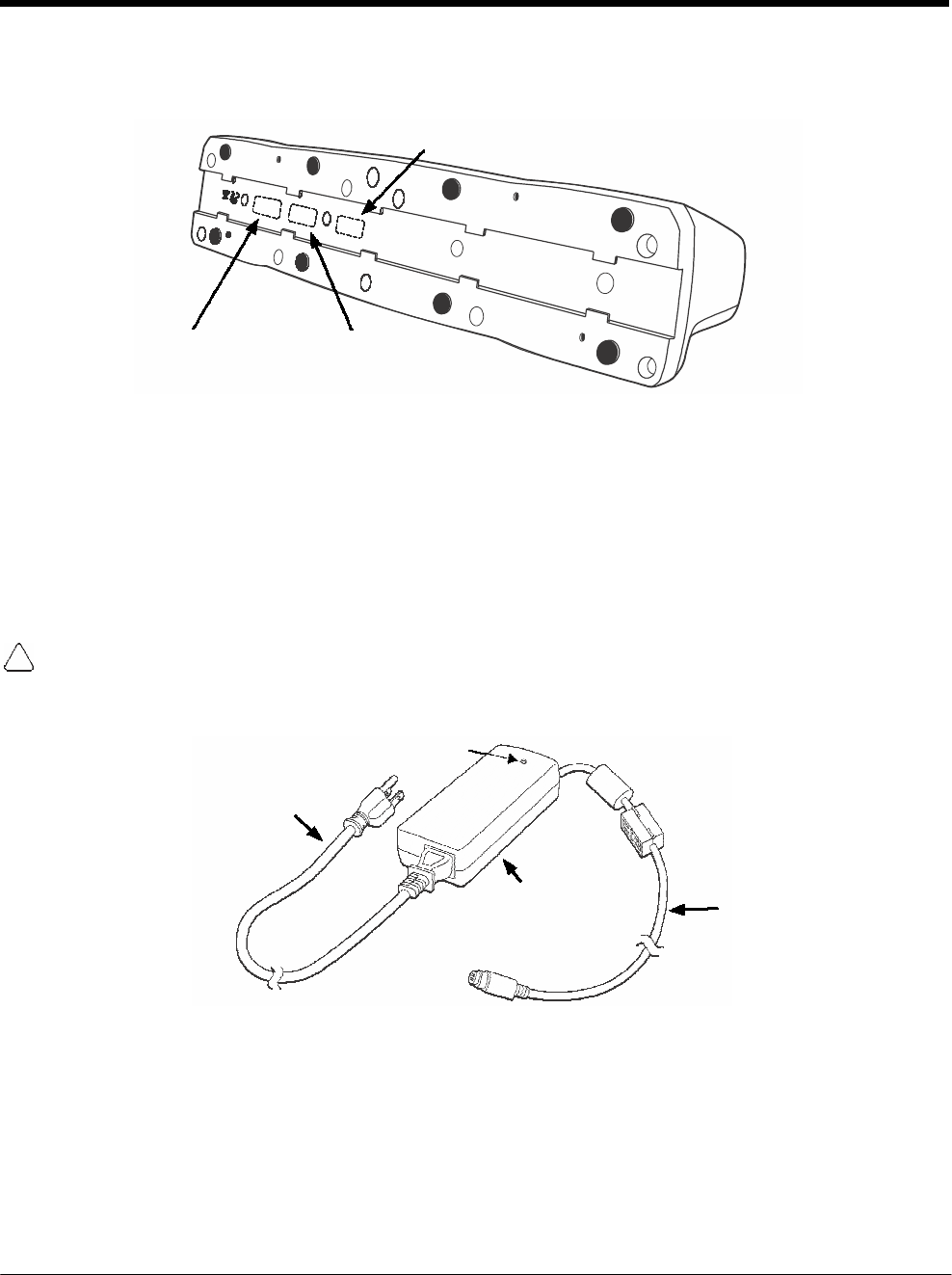
DRAFT COPY 11/11/11
16 - 4
Label
Se
r
ial
Number
Bottom Panel
For details on how to mount the Net Base, see Mounting the Net Base on page 16-6.
MAC Address
Label
Compliance
Label
Power
The terminal requires 12 Volts DC input for communications and battery charging; the power adapter on
the power cable converts the voltage from the power source to 12 volts DC. Use only a UL Listed power
supply with output rated 12VDC, 8.5A with the device, which has been qualified by Honeywell. The oper-
ating temperature range is -10° to 45°C (14° to 113°F).
Honeywell recommends that you leave the Net Base connected to its power source at all times, so that it
is always ready to use.
We recommend use of Honeywell peripherals, power cables, and power adapters. Use of any non-Honeywell
peripherals, cables, or power adapters may cause damage not covered by the warranty.
Connecting Power to the Net Base
Power
LED
A/C Power Cord
Power
Adapter
Power Connector Cable
1. Plug the A/C power cord into the power adapter.
2. Plug the power connector cable into the power connector on the back of the Net Base.
3. Plug the A/C power cord into a standard wall outlet. The LED on the Power Adapter illuminates to
indicate power.
4. All four Power/Dock LEDs illuminate solid red to indicate the base has power. Terminal wells with
properly docked Dolphins indicate power with a green LED.
5. The base is ready to begin charging terminals.
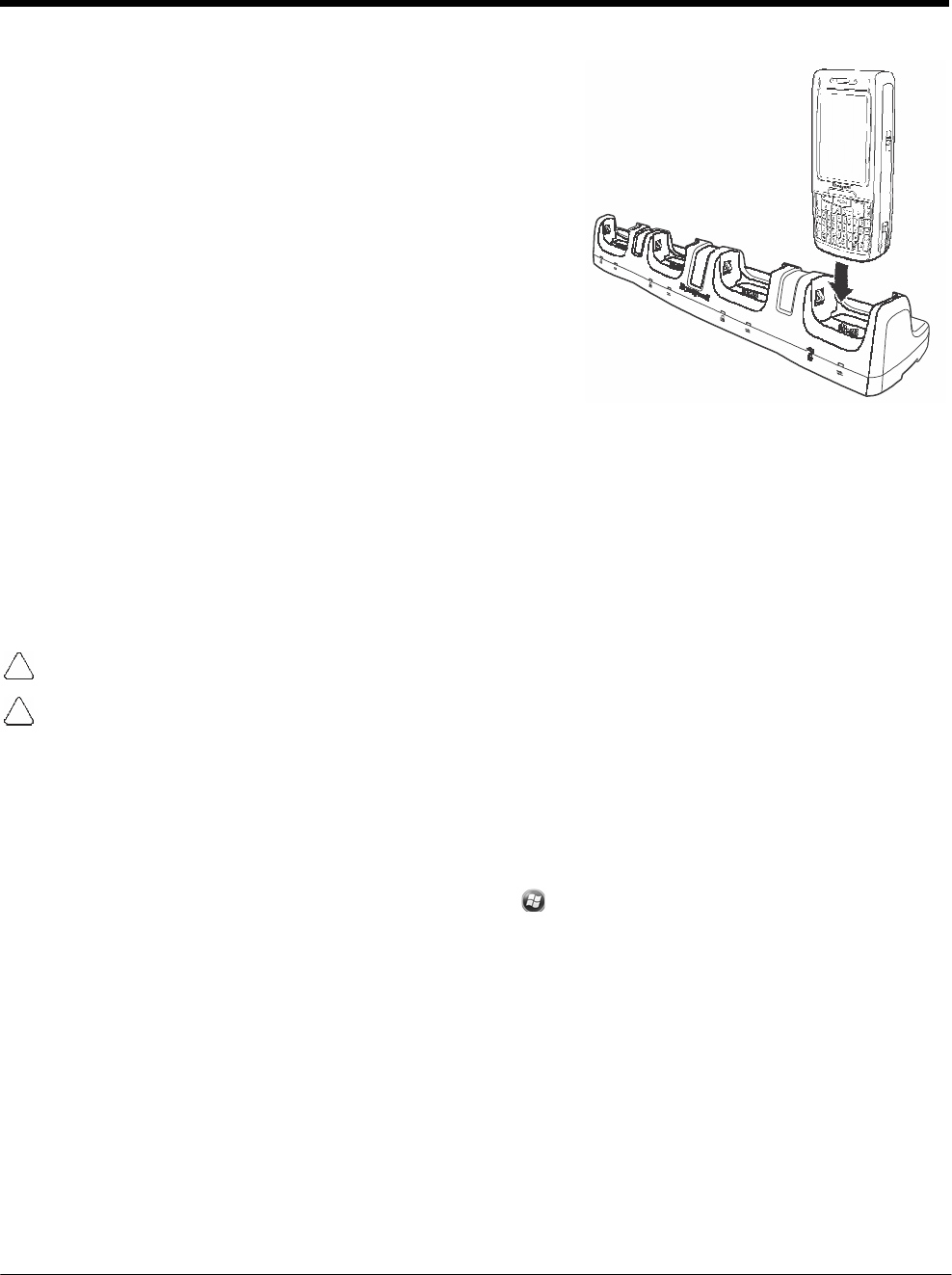
DRAFT COPY 11/11/11
16 - 5
Charging the Main Battery
The base provides power to the Dolphin terminals and allows
the charging of the main batteries in the terminals. The main
battery of each terminal charges in 4 hours for the standard
battery or
6 hours for the extended battery. The intelligent battery charg-
ing system incorporated into all Dolphin terminals prevents
overcharging, which means that Dolphin terminals may be
stored in the base indefinitely without damage to the terminals,
battery packs, or the base.
For more information about Honeywell battery packs and how
to check battery power levels in your terminal, refer to Power
(page 7-15) and Batteries (page 3-12).
To Power a Terminal and Charge its Main Battery
1. Verify the main battery pack is installed in the terminal and the battery lock is engaged, see Install
the Main Battery Pack on page 2-1.
2. Verify the base has power. If the Power/Dock LEDs are not illuminated, see Connecting Power to
the Net Base on page 16-4.
3. Slide the Dolphin terminal into one of the four terminal wells. The Power/Dock LED for the well
changes to green. Charging begins immediately if required by the Dolphin terminal.
Ensure all components are dry prior to mating terminals/batteries with peripheral devices. Mating wet
components may cause damage not covered by the warranty.
We recommend use of Honeywell Li-Ion battery packs. Use of any non-Honeywell battery may result in
damage not covered by the warranty.
Communication
Software Requirements
Before you connect the Dolphin terminal to the Net Base, make sure you have the most current software
installed. To check the terminal’s system information, tap > Power Tools > SysInfo.
Applications on the Dolphin Terminal
Applications running on the Dolphin terminal when it is connected to the Net Base should be designed
specifically for a partially connected network. For more details, please refer to the Best Practices for Par-
tially Connected Networks document available at www.honeywellaidc.com.

DRAFT COPY 11/11/11
16 - 6
Connecting the Dolphin Terminal to the Net Base
By default, the Dolphin terminal is configured to obtain IP addresses automatically using a DHCP server.
This means that in most cases, you would simply plug-and-play the unit.
1. Verify the base has power. If the Power/Dock LEDs are not illuminated, see Connecting Power to
the Net Base on page 16-4.
2. Plug the CAT-5 Ethernet cable into one of the RJ45 connectors on the back of the Net Base.
3. Plug the Ethernet cable into the network.
4. Insert the Dolphin into one of the terminal wells. The DOCK LED for the well changes from red to
green and the connection icon on the Dolphin’s title bar changes from
x
to .
5. By default, the DHCP server assigns a unique IP address to each of the Dolphin terminals docked in
the Net Base. This IP address can be used by any application on the Dolphin terminal.
Note: Instead of using the default for DHCP assigned IP addresses, the Dolphin terminal can use a statically
assigned IP address. See standard Microsoft Windows Mobile documentation for how to assign a static IP
address to a network adapter. In this case, set a static IP address for the adapter named "SMC95001 USB2.0
FAST Ethernet
Drive".
Displaying the Net Base Terminal Well and Dolphin IP Address
Once the Dolphin terminal establishes communication, it uses the unique IP address assigned to the ter-
minal well it is docked in on the Net Base. If four Dolphin terminals are successfully connected, then four
different IP addresses are assigned to the adapter associated with the Dolphin terminal.
1. Tap > Power Tools > Network Utilities > IPConfig.
2. Change the Adapter to SMC95001.
3. On the Input tab, tap the Display full configuration button.
4. The Dolphin terminal retrieves and displays the IP configuration for the entire Dolphin terminal and
the Net Base terminal well where the Dolphin is docked.
5. Locate the IpAddress field in the IP configuration list.
Mounting the Net Base
Set the Net Base on a dry, stable surface, such as a desktop or workbench near an electrical outlet. Be
sure to provide enough workspace with good lighting for the user to view and operate the Dolphin termi-
nal while it is in the Net Base. When choosing a location, bear in mind that the mounting location must
allow users easy access to the terminal wells, the Ethernet ports, and the power jack.
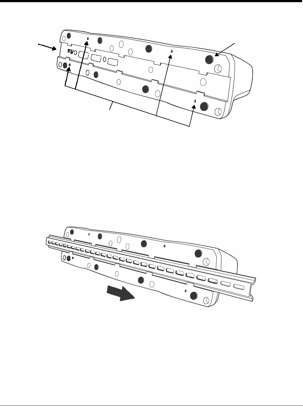
DRAFT COPY 11/11/11
16 - 7
Bottom Panel
DIN Rail Slot Rubber Feet, Qty. 8
Optional Mounting Holes for M3 self
tapping screws, Qty. 4. Maximum
thread depth of 7 mm.
Desk Mounting
The DIN Rail (7.5 X 35 mm) slot on the bottom panel enables secure mounting on a horizontal surface.
Hardware Required
• 3/16 in. dia x 5/8 in. long pan head screw
• 1/2 in. OD x 7/32 in. ID x 3/64 in. thick
• 3/16 in. dia nut
Installing the DIN Rail
1. Slide the DIN Rail into the DIN Rail slot on the bottom panel of the base.
2. Turn the base and DIN Rail right side up.
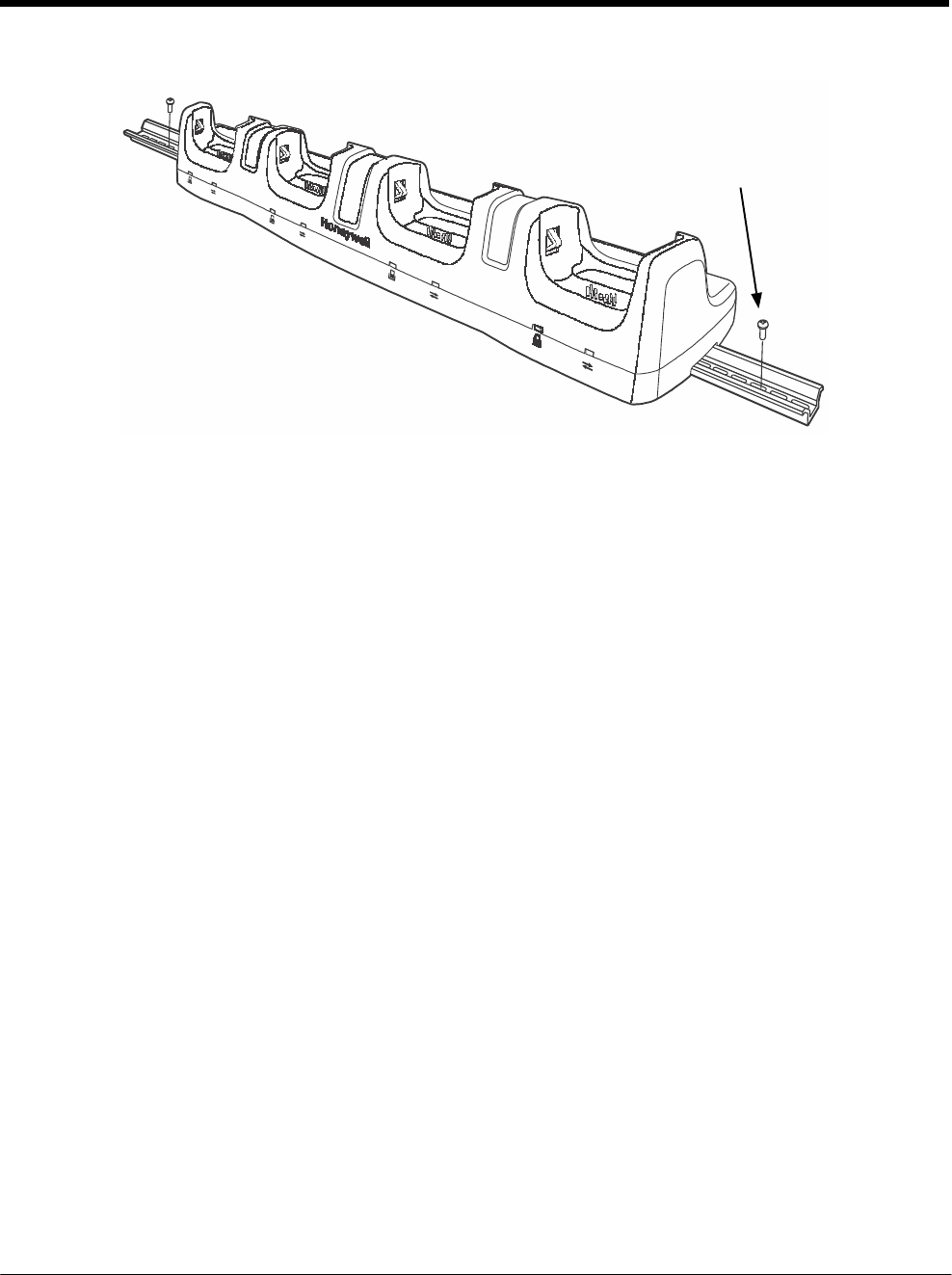
DRAFT COPY 11/11/11
16 - 8
3. Then, using the appropriate nuts and bolts, secure the DIN Rail to a stable, flat horizontal surface.
DIN Rail (7.5 x 35
mm)

17 - 1
17 DRAFT COPY 11/11/11
Dolphin
7800
QuadCharger Device (Model
7800-QC)
Overview
This 4-slot charging station provides intelligent battery management for the rechargable battery packs
used in Dolphin terminals.
The 7800-QC charger is designed for use with standard battery pack model 7800-BTSC or 7800-
BTSCW (Li-ion 3.7 V, 8.9 watt hour) and extended battery pack model 7800-BTXC or 7800-BTXCW (Li-
ion 3.7 V, 14.8 watt hour) manufactured for Honeywell International Inc.
Warning! The QuadCharger is not designed for use in hazardous locations.
We recommend use of Honeywell peripherals, power cables, and power adapters. Use of any
non-Honeywell peripherals, cables, or power adapters may cause damage not covered by the warranty.
Unpacking the QuadCharger
Open the shipping box and inspect the package to see that the following standard items are included:
• One QuadCharger, model 7800-QC
• One power supply (see Power on page 17-3)
• One power cord
These items are needed to operate the QuadCharger. If any items are missing or anything appears to be
damaged, contact your Customer Account Representative. Keep the original packaging in case you
need to return the HomeBase for service or to store the HomeBase while not in use.
Charging Overview
Each charging slot works independently of the other three. As battery packs charge, the charging cir-
cuitry follows the two-step charging process (CC-CV) that is recommended for the battery type. The pro-
cess monitors changes in temperature, current, and voltage and resets the battery pack. Charge time is
4 hours for the standard battery or 6 hours for the extended battery.
Note: Before attempting to use, charge, or replace the battery in the terminal, you should read the Guidelines for
Battery Pack Use and Disposal on page 3-13.
Capacity
The charger holds 4 Honeywell standard or extended batteries.
We recommend use of Honeywell Li-Ion battery packs. Use of any non-Honeywell battery may result in
damage not covered by the warranty.
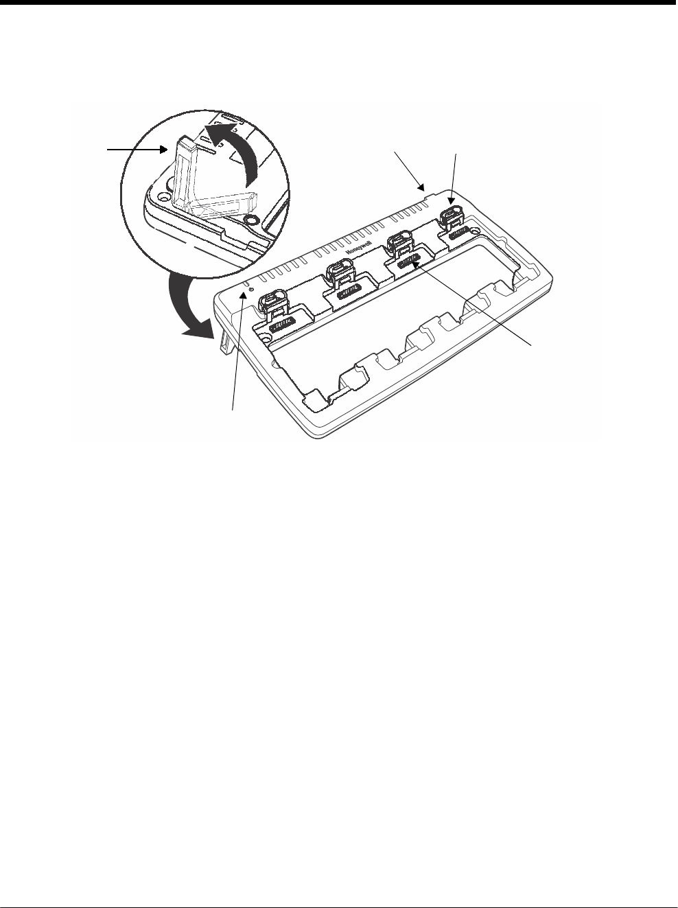
DRAFT COPY 11/11/11
17 - 2
Parts and Functions
Top Panel
Support
Legs
Qty.
2
Power Supply
Connector Status LEDs
Qty. 1 Per Charging Slot
Charging
Slots
Qty.
4
Power LED
Charging Slots
There are four charging slots. Each slot holds one battery and charges it independently of the
other slots. Charging immediately begins when a battery is placed in a slot.
Power LED
The power LED indicates if the QuadCharger is powered. When the QuadCharger is receiving
power, the LED illuminates green.
Power Supply Connector
You attach the power supply to this connector. See Power on page 17-3.
Status LEDs
Each of the four battery slots has a dedicated status LED. The color of the LED indicates the
charge status of the battery in the slot.
Color This color indicates that the battery in the slot…
Green (Solid) Has completed its charge cycle and is ready for use.
Orange (Solid) Is being charged at a maximum charge rate.
Red (Flashing) The internal temperature of the auxiliary battery is too hot or there
is a battery error. Charge the auxiliary battery in a cooler
environment or replace the battery with a new Honeywell battery.
For more information, see Troubleshooting on page 17-5.
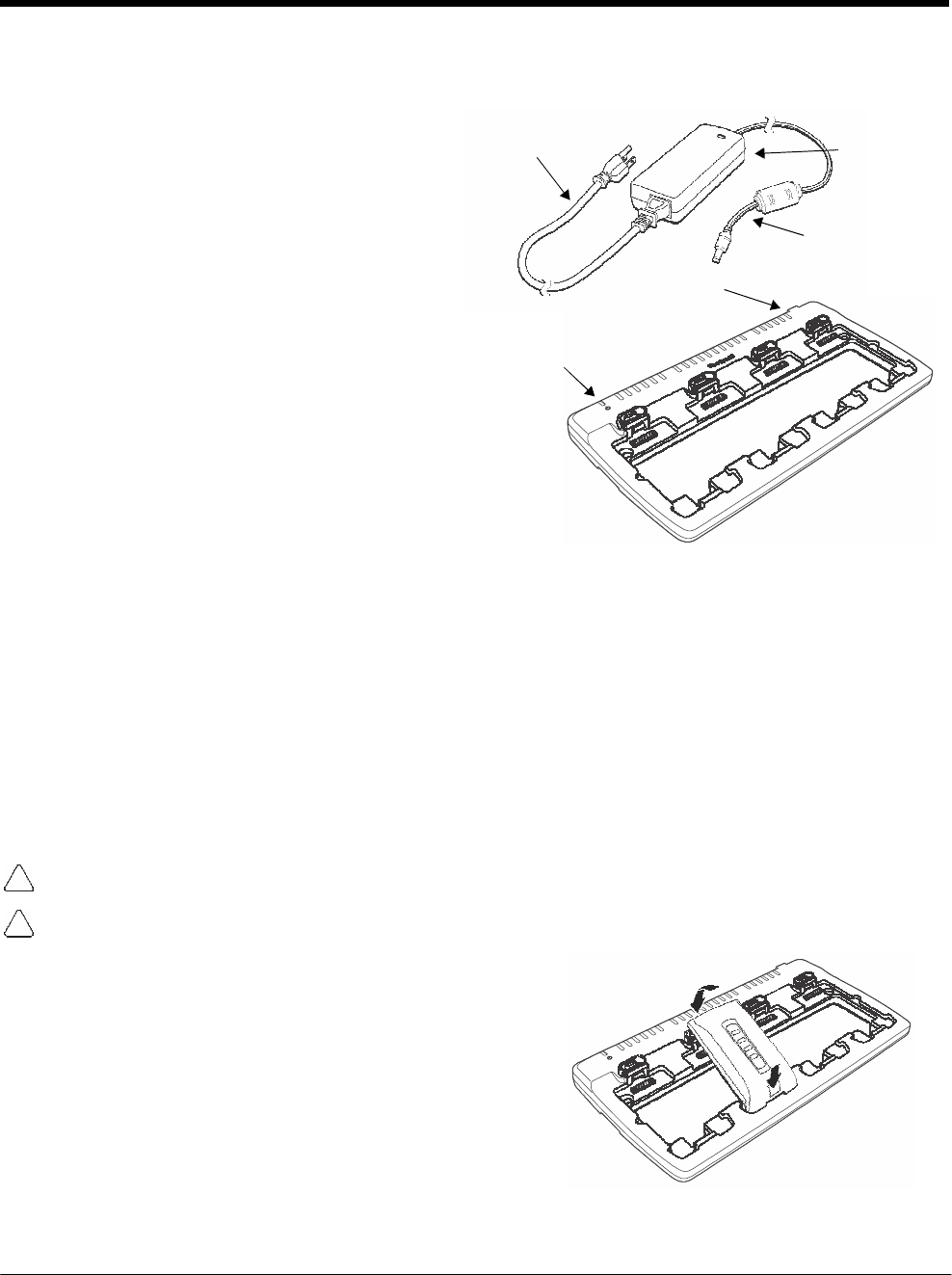
DRAFT COPY 11/11/11
17 - 3
3
Power
The charger must be connected to a power
source via the Honeywell power adapter cable so
that voltage is adjusted appropriately. Use only a
UL listed power supply, which has been qualified
by Honeywell with output rated at 12VDC and
3 amps with the device.
1. Plug the AC power cord into the power
adapter.
2. Plug the power cable into the power
connector on the back of the charger.
3. Plug the AC power cord into a grounded
power source.
4. The power LED illuminates green, and the
charger performs a self-diagnostic test that
lasts approximately five seconds.
AC Power
Cord
Power
LED
Power Supply
Connector
Power
Adapter
Power Cable
Recommendations for Storing Batteries
To maintain top performance from batteries, avoid storing batteries outside of the following temperature
ranges:
• 14°F to 113°F (-10°C to +45°C) for short term storage of less than one month
• 32°F to 86°F (-0°C to +30°C) for long term storage
Do not store batteries in extremely high humidity. For prolonged storage, do not keep batteries stored in
a charger that is connected to a power source.
Inserting and Charging Batteries
For best results, battery packs should be at room temperature before recharging them; temperature has
a marked effect on charging. The recommended temperature range is 50°F to 95° F (10°C to 35° C).
Ensure all components are dry prior to mating terminals/batteries with peripheral devices. Mating wet
components may cause damage not covered by the warranty.
We recommend use of Honeywell Li-ion battery packs. Use of any non-Honeywell battery may result in
damage not covered by the warranty.
1. Connect power to the charger, see Power above.
2. Insert the battery at an angle.
Note: Align the battery contacts with the contacts inside the
QuadCharger battery well.
3. Snap the battery into place with a hinging motion.
4. The Status LED for that particular slot illuminates 2
orange to indicate the battery is seated properly and
the charging cycle has begun.
5. When the Status LED turns green, the battery in the slot has completed charging.
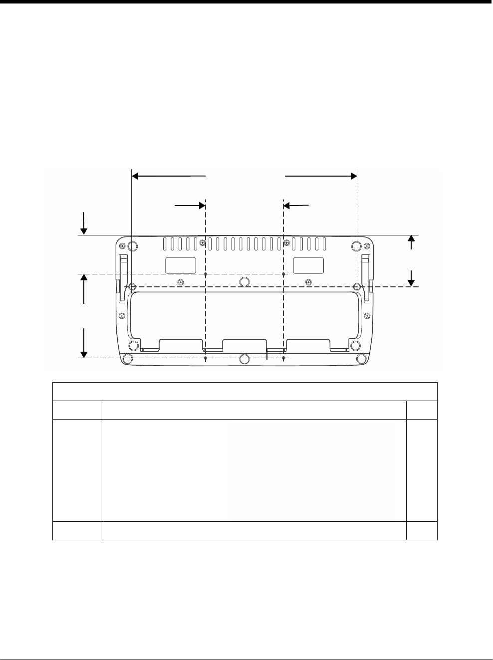
DRAFT COPY 11/11/11
17 - 4
Mounting the QuadCharger
The charger should be located on a dry, stable surface and can be mounted on a flat, horizontal surface
such as a desktop or workbench. When choosing a location, always bear in mind that:
• the mounting location must allow users easy access to the power connector.
• the charger should be oriented so that users can easily insert and remove battery packs and see the
status LEDs.
Optional Hardware Mount
Bottom Panel
268.6 mm [10.57 in.]
93 mm [3.66
in.]
45mm
[1.77 in.]
B
B
A
A
60 mm
[2.36 in.]
90 mm
[3.54 in.]
B
B
Optional Mounting
Holes
Option Size Qty.
A 6 mm [0.24 in.] Dia. thru hole
for #6 Flat Head Phillips Dry-
wall-to-Wood Screws
2
B Mounting holes for M3 self tapping screws, maximum thread depth of 7 mm 4

DRAFT COPY 11/11/11
17 - 5
Troubleshooting
If you encounter problems with your QuadCharger device, refer to chart below for possible solutions.
If problems persist, please contact Honeywell Technical Support.
Problem Issue
The Status LED does not come on when I
insert a battery pack.
Check the power connections; make sure the Power cable is
inserted into the Power supply connector and the battery pack
is properly seated.
The Status LED lights red during charging.
Try to charge the battery in one of the other charging slots. If
the red Status LED comes on again, then the problem is
associated with the battery pack. If the red status stays with the
charging slot, the problem is associated with the charging
circuitry.
The Status LED flashes red without a
battery in the charging slot.
If a battery is in failuare mode (flashing red LED), and that
battery is removed from the charging slot, the slot does not
reset and will continue to flash red. To reset the slot and stop
the flashing red LED, insert a known good battery into the slot
or recycle the power to the QuadCharger.

DRAFT COPY 11/11/11
17 - 6

18 - 1
18 DRAFT COPY 11/11/11
Customer
Support
Product Service and Repair
Honeywell International Inc. provides service for all its products through service centers throughout the
world. To obtain warranty or non-warranty service, contact the appropriate location below to obtain a
Return Material Authorization number (RMA #) before returning the product.
North America
Telephone: (800) 782-4263
E-mail: hsmnaservice@honeywell.com
Latin America
Telephone: (803) 835-8000
Telephone: (800) 782-4263
Fax: (239) 263-9689
E-mail: laservice@honeywell.com
Brazil
Telephone: +55 (11) 5185-8222
Fax: +55 (11) 5185-8225
E-mail: brservice@honeywell.com
Mexico
Telephone: 01-800-HONEYWELL (01-800-466-3993)
Fax: +52 (55) 5531-3672
E-mail: mxservice@honeywell.com
Europe, Middle East, and Africa
Telephone: +31 (0) 40 2901 633
Fax: +31 (0) 40 2901 631
E-mail: euroservice@honeywell.com
Hong Kong
Telephone: +852-29536436
Fax: +852-2511-3557
E-mail: apservice@honeywell.com
Singapore
Telephone: +65-6842-7155
Fax: +65-6842-7166
E-mail: apservice@honeywell.com
China
Telephone: +86 800 828 2803
Fax: +86-512-6762-2560
E-mail: apservice@honeywell.com
Japan
Telephone: +81-3-6730-7344
Fax: +81-3-6730-7222
E-mail: apservice@honeywell.com
Online Product Service and Repair Assistance
You can also access product service and repair assistance online at www.honeywellaidc.com.

DRAFT COPY 11/11/11
18 - 2
For ongoing and future product quality improvement initiatives, the 7800 comes equipped with an
embedded device lifetime counter function. Honeywell may use lifetime counter data for future statistical
reliability analysis as well as ongoing quality, repair and service purposes.
Technical Assistance
If you need assistance installing or troubleshooting your device, please call your distributor or the near-
est technical support office:
North America/Canada
Telephone: (800) 782-4263
E-mail: hsmnasupport@honeywell.com
Latin America
Telephone: (803) 835-8000
Telephone: (800) 782-4263
E-mail: hsmlasupport@honeywell.com
Brazil
Telephone: +55 (11) 5185-8222
Fax: +55 (11) 5185-8225
E-mail: brsuporte@honeywell.com
Mexico
Telephone: 01-800-HONEYWELL (01-800-466-3993)
E-mail: soporte.hsm@honeywell.com
Europe, Middle East, and Africa
Telephone: +31 (0) 40 7999 393
Fax: +31 (0) 40 2425 672
E-mail: hsmeurosupport@honeywell.com
Hong Kong
Telephone: +852-29536436
Fax: +852-2511-3557
E-mail: aptechsupport@honeywell.com
Singapore
Telephone: +65-6842-7155
Fax: +65-6842-7166
E-mail: aptechsupport@honeywell.com
China
Telephone: +86 800 828 2803
Fax: +86-512-6762-2560
E-mail: aptechsupport@honeywell.com
Japan
Telephone: +81-3-6730-7344
Fax: +81-3-6730-7222
E-mail: aptechsupport@honeywell.com
Online Technical Assistance
You can also access technical assistance online at www.honeywellaidc.com.

DRAFT COPY 11/11/11
18 - 3
Limited Warranty
Honeywell International Inc. ("HII") warrants its products and optional accessories to be free from defects
in materials and workmanship and to conform to HII’s published specifications applicable to the products
purchased at the time of shipment. This warranty does not cover any HII product which is (i) improperly
installed or used; (ii) damaged by accident or negligence, including failure to follow the proper
maintenance, service, and cleaning schedule; or (iii) damaged as a result of (A) modification or alteration
by the purchaser or other party, (B) excessive voltage or current supplied to or drawn from the interface
connections, (C) static electricity or electro-static discharge, (D) operation under conditions beyond the
specified operating parameters, or (E) repair or service of the product by anyone other than HII or its
authorized representatives.
This warranty shall extend from the time of shipment for the duration published by HII for the product at
the time of purchase ("Warranty Period"). Any defective product must be returned (at purchaser’s
expense) during the Warranty Period to HII factory or authorized service center for inspection. No product
will be accepted by HII without a Return Materials Authorization, which may be obtained by contacting
HII. In the event that the product is returned to HII or its authorized service center within the Warranty
Period and HII determines to its satisfaction that the product is defective due to defects in materials or
workmanship, HII, at its sole option, will either repair or replace the product without charge, except for
return shipping to HII.
EXCEPT AS MAY BE OTHERWISE PROVIDED BY APPLICABLE LAW, THE FOREGOING
WARRANTY IS IN LIEU OF ALL OTHER COVENANTS OR WARRANTIES, EITHER EXPRESSED OR
IMPLIED, ORAL OR WRITTEN, INCLUDING, WITHOUT LIMITATION, ANY IMPLIED WARRANTIES
OF MERCHANTABILITY OR FITNESS FOR A PARTICULAR PURPOSE, OR NON-INFRINGEMENT.
HII’S RESPONSIBILITY AND PURCHASER’S EXCLUSIVE REMEDY UNDER THIS WARRANTY IS
LIMITED TO THE REPAIR OR REPLACEMENT OF THE DEFECTIVE PRODUCT WITH NEW OR
REFURBISHED PARTS. IN NO EVENT SHALL HII BE LIABLE FOR INDIRECT, INCIDENTAL, OR
CONSEQUENTIAL DAMAGES, AND, IN NO EVENT, SHALL ANY LIABILITY OF HII ARISING IN
CONNECTION WITH ANY PRODUCT SOLD HEREUNDER (WHETHER SUCH LIABILITY ARISES
FROM A CLAIM BASED ON CONTRACT, WARRANTY, TORT, OR OTHERWISE) EXCEED THE
ACTUAL AMOUNT PAID TO HII FOR THE PRODUCT. THESE LIMITATIONS ON LIABILITY SHALL
REMAIN IN FULL FORCE AND EFFECT EVEN WHEN HII MAY HAVE BEEN ADVISED OF THE
POSSIBILITY OF SUCH INJURIES, LOSSES, OR DAMAGES. SOME STATES, PROVINCES, OR
COUNTRIES DO NOT ALLOW THE EXCLUSION OR LIMITATIONS OF INCIDENTAL OR
CONSEQUENTIAL DAMAGES, SO THE ABOVE LIMITATION OR EXCLUSION MAY NOT APPLY TO
YOU.
All provisions of this Limited Warranty are separate and severable, which means that if any provision is
held invalid and unenforceable, such determination shall not affect the validity of enforceability of the
other provisions hereof. Use of any peripherals not provided by the manufacturer may result in damage
not covered by this warranty. This includes but is not limited to: cables, power supplies, cradles, and
docking stations. HII extends these warranties only to the first end-users of the products. These
warranties are non-transferable.
The limited duration of the warranty for the Dolphin 7800 is as follows:
• The duration of the limited warranty for terminals with an integrated imager is one year.
• The duration of the limited warranty for touch screens is one year.
• The duration of the limited warranty for the Dolphin 7800 HomeBase device, Dolphin 7800 eBase
device, Dolphin 7800 Net Base device, Dolphin 7800 QuadCharger device, Dolphin 7800 Mobile Base,
and Dolphin 7800 ChargeBase device, is one year.
• The duration of the limited warranty for batteries is one year.
Use of any battery from a source other than Honeywell may result in damage not covered by the
warranty. Batteries returned to Honeywell International Inc. in a reduced state may or not be replaced
under this warranty. Battery life will be greatly increased when following the battery instructions in this
user’s guide.

DRAFT COPY 11/11/11
18 - 4
How to Extend Your Warranty
Honeywell International Inc. offers a variety of service plans on our hardware products. These
agreements offer continued coverage for your equipment after the initial warranty expires. For more
information, contact your Sales Representative, Customer Account Representative, or Product Service
Marketing Manager from Honeywell International Inc., or your Authorized Reseller.

DRAFT COPY 11/11/11

DRAFT COPY 11/11/11
Honeywell Scanning & Mobility
9680 Old Bailes Road
Fort Mill, SC 29707
www.honeywellaidc.com
78-UG Rev
(a)
11/11