Honeywell 8DLTSSCBASE Security Base Control Unit User Manual 800 13956V1 A TSSC SYSTEM qig
Honeywell International Inc. Security Base Control Unit 800 13956V1 A TSSC SYSTEM qig
Contents
- 1. Users Manual Rev B
- 2. Quick Install Guide
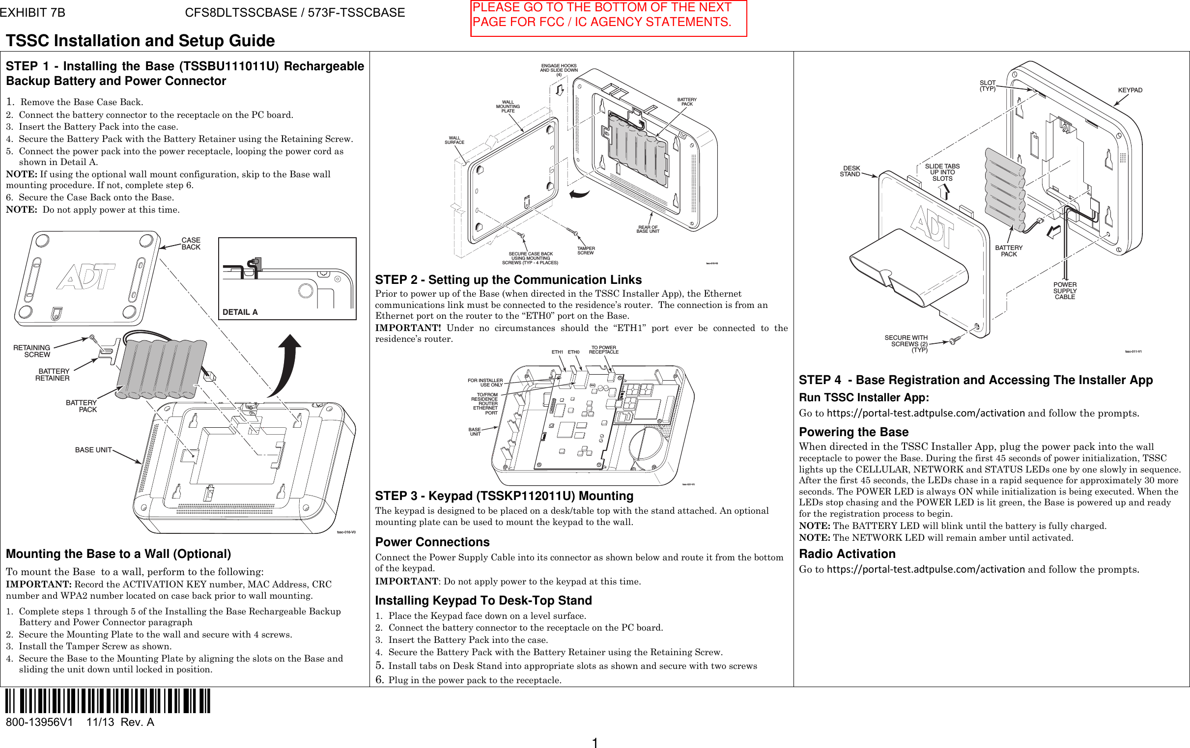
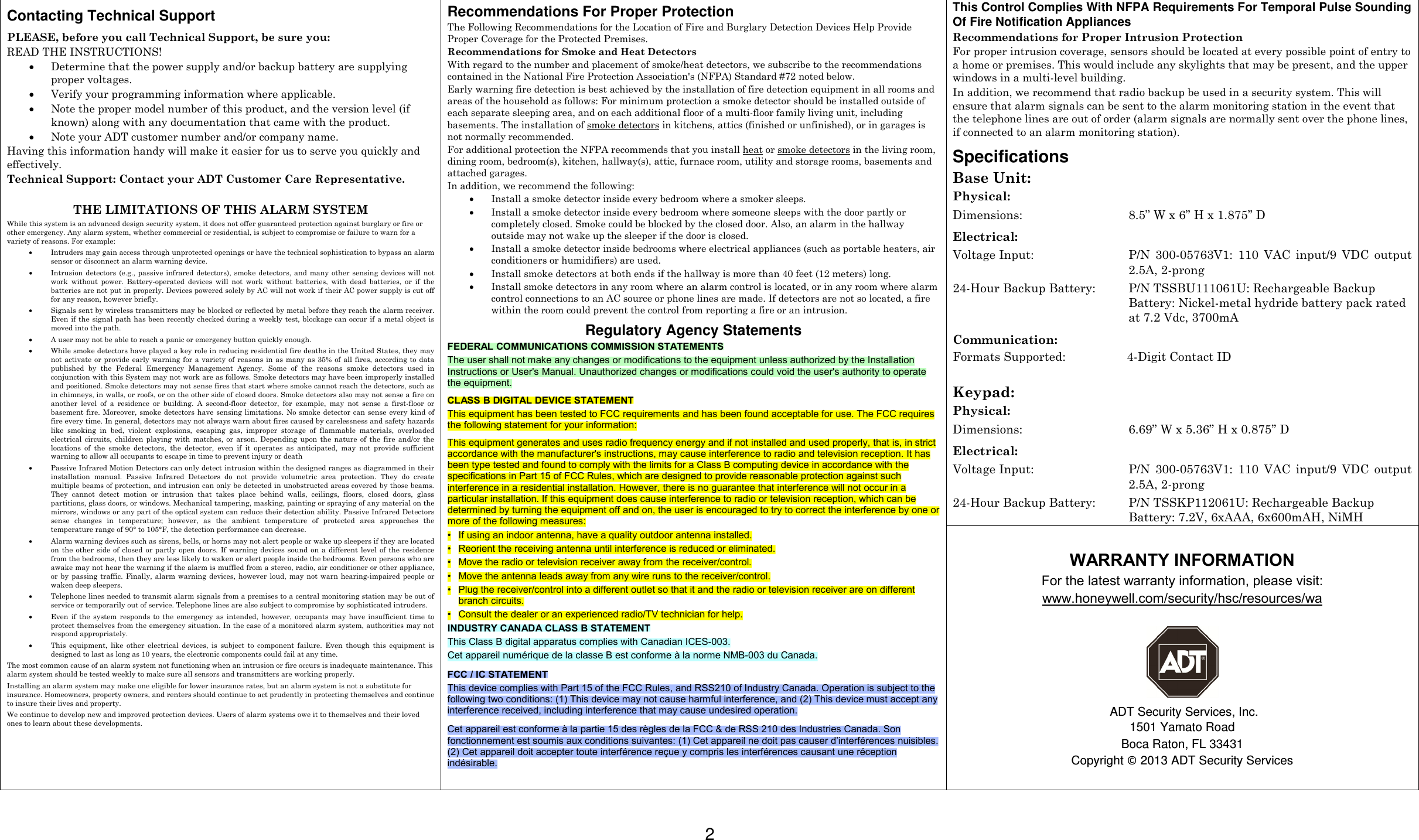
Quick Install Guide