Honeywell 9500LUP Hand Held PC with GSM 850/1800/1900, WLAN and BT User Manual
Honeywell International Inc Hand Held PC with GSM 850/1800/1900, WLAN and BT
Contents
- 1. User Manual Part 1
- 2. User Manual Part 2
User Manual Part 2

7 - 36 Dolphin® 9500 Series Mobile Computer User’s Guide - Preliminary Rev (d) 12/17/04
Advice and Workarounds
Issue Possible Causes and Solutions
The Client will not start on the device with
an error message about missing files.
Perform a soft reset.
The wireless network interface (port) does
not appear in the main AEGIS screen.
• The license is not valid (If you have entered a time-limited license, is
your clock on the device correct?).
• Restart the client - on the main screen tap Client > Restart.
• Perform a soft reset.
• If the radio is turned off or the radio card is not present, this will
sometimes cause the port name to not appear.
• If the radio driver is very old and does not support NDIS 5.1
commands, the Client may not be able to detect it.
The wireless network interface appears, but
when I select it and go to the "configure"
menu, the Scan button is disabled.
Power up the radio; see Powering Up Radios and Radio Combinations
on page 4-7.
The client is not attaching to the correct
access point.
The default network profile instructs the client to attach to the first
available access point. You must select a network, move it to the
Configured Networks list, and then move it above default in the list using
the up arrow buttons.
For more information, see Wireless Networks Tab on page 7-29.
The Client is failing authentication even
though all my information was entered
correctly.
1. Verify that the network profile for the access point corresponds to the
authentication profile you created for it.
• Select the network profile in the Configured Networks list.
• Tap Properties. The Profile Info tab opens - see page 7-32.
• In the Authentication profiles drop-down list, select the profile
you want to review.
• Tap View. The User tab appears displaying the profile’s
information.
2. Verify that you have configured the identity and password into the
correct fields on the User tab (page 7-32) in the authentication profile.
If you are using PEAP or TTLS, the username and password are
entered in the Tunneled authentication section.
My Access Point does not broadcast its
SSID. Even though I have manually
configured an access point with that name,
the Client won't associate with it.
• Make sure that the desired SSID is listed as the Network Name, not
the Network Profile (which is a screen label)
• Verify that Do Active Scan is selected on the Profile Info tab; see Do
active scan on page 7-32. Otherwise, the Client will not attempt to find
the access point.
I am authenticated, but I don't get an IP
address through DHCP.
On the main screen, tap and hold on your access point, tap Configure on
the popup menu, and select the Protocol tab. Verify that Renew IP
Address is selected; see Renew IP address on page 7-30.
I cannot attach to my old network that does
not support 802.1x authentication, but is
using WEP encryption.
• Verify that you can see your SSID in the Available Networks list on the
Wireless Networks tab. Move the SSID to the top of the Configured
Networks list so that it is accessed first. If the SSID is not there, you
can add it manually and enter the SSID as the network name - page
7-29
• Select the SSID and tap Properties.
• On the Profile Info tab, select Do active scan if your access point
does not broadcast its SSID.
• On the WEP Mgmt tab, select Use key for data encryption and Use
key to authenticate with AP.
• Enter the WEP Key - see Key on page 7-33.
• On the Protocol tab, select Renew IP Address (unless you have
entered one manually separate from the Client)
• Note that the port status indicator in the main screen reads
"Associated," not "Authenticated" when the connection is complete;
although the log file will indicate "Entered AUTHENTICATED state."

Dolphin® 9500 Series Mobile Computer User’s Guide - Preliminary Rev (d) 12/17/04 7 - 37
I made changes, but they do not appear to
have taken effect.
Always tap OK before exiting a screen you have changed. Then restart
the Client from the Client menu on the main screen.
How do I enable peer-to-peer (ad-hoc) mode
to have two clients communicate without an
access point?
• On the Wireless Networks tab, add a new profile to the Configured
Network list.
• On the Profile Info tab, give each side the same network name (SSID).
• Select Peer-to-Peer Group (ad hoc mode) and Do active scan.
• On the WEP management section, select Use key for data encryption
and enter an identical key for both clients.
• Verify that this network profile is the first (or only) one in the
Configured Network list and try to restart both clients at roughly the
same time.
Advice and Workarounds
Issue Possible Causes and Solutions
7 - 38 Dolphin® 9500 Series Mobile Computer User’s Guide - Preliminary Rev (d) 12/17/04
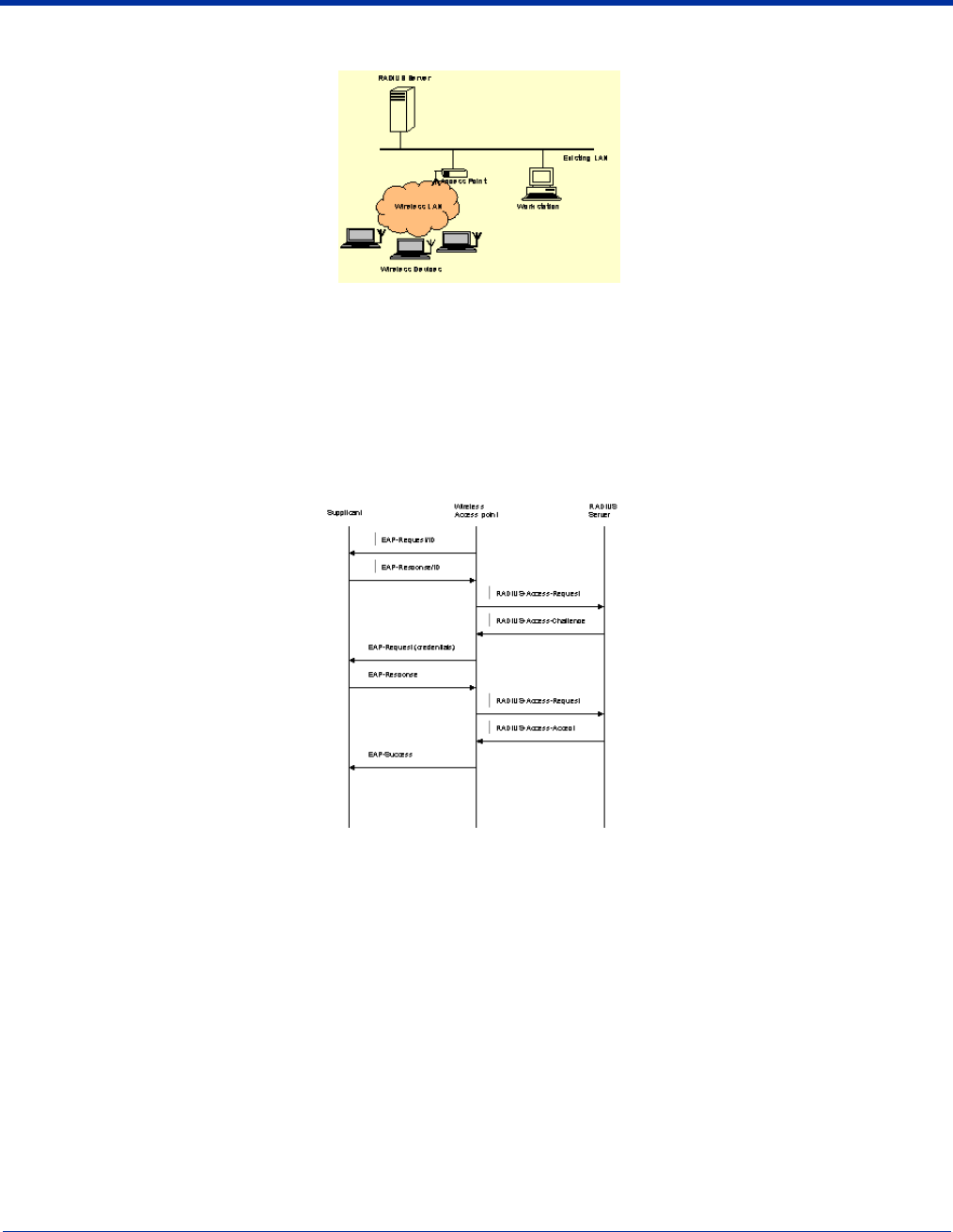
How 802.1X Works
The network elements in the above graphics are those involved in a typical wireless LAN. When 802.1X is running, a wireless
device must authenticate itself with the access point in order to get access to the Existing LAN. With respect to the terms used
in the 802.1X standard, access points (APs) function as authenticators and wireless devices function as supplicants. The
authenticator keeps a control port status for each Client it is serving. If a Client has been authenticated, its control port status is
said to be Authorized, and the Client can send application data to the LAN through the AP. Otherwise, the control port status is
said to be Unauthorized, and application data cannot traverse the AP.
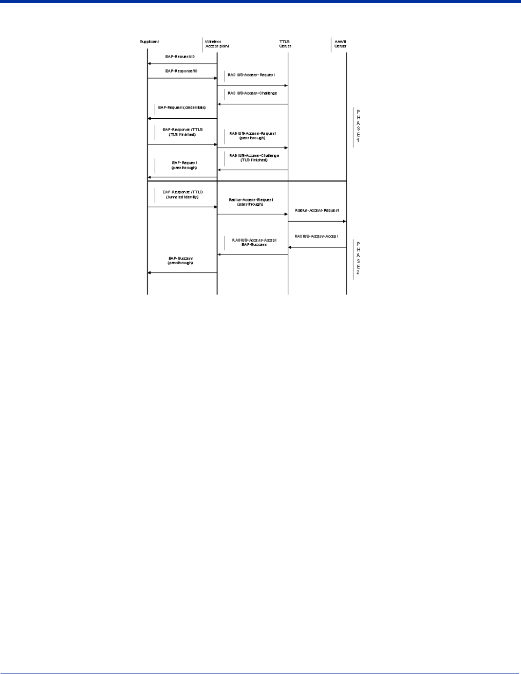
Typical Message Exchange Using MD5 or TLS
The above graphic displays the typical message exchange when the device and the AP support 802.1X. When an AP acting as
an authenticator detects a wireless station on the LAN, it sends an EAP-Request for the user's identity to the terminal. In turn,
the terminal responds with its identity, and the AP relays this identity to an authentication server, which is typically an external
RADIUS server.
The RADIUS server can then act as a central repository of user profile information. Such use of a centralized authentication
server allows the user to access wireless LANs at many different points, but still be authenticated against the same server. In
response to the Access-Request, the RADIUS server sends an Access-Challenge to the AP, which is then relayed in the form of
an EAP-Request to the device. The device sends its credentials to the AP, which in turn relays them to the RADIUS server. The
RADIUS server determines whether access to the network is accepted or denied based on the Client's credentials.
Dolphin® 9500 Series Mobile Computer User’s Guide - Preliminary Rev (d) 12/17/04 7 - 39
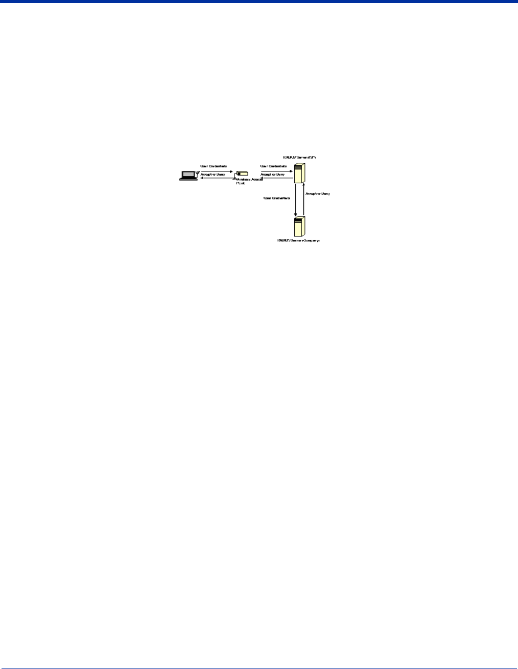
Typical Message Exchange Using TTLS and PEAP
The above graphic shows a typical message flow for a TTLS transaction. TTLS authentication comprises two phases. In Phase
1, TLS is used to authenticate the TTLS server to the client. The TTLS server may optionally request authentication of the client's
certificate, but by default the client verifies only the server's certificate. The TLS handshake is negotiated between the client and
the TTLS server. Following the TLS handshake, Phase 2 may proceed using a secure channel (tunnel) provided by the TLS
record layer. The secure tunnel is then used to exchange information for the negotiation of the following legacy protocols: EAP-
MD5, PAP, CHAP, MS-CHAP, or MS-CHAPV2 (subject to support by the AAA server). A TTLS server may perform the
authentication, or the information may be de-tunneled and passed on to an AAA server. The AAA server is the server in the user's
home domain where authentication and authorization are administered.
PEAP works in the same manner as TTLS. However, supports different legacy protocols within the encrypted Phase 2 tunnel.
Currently the tunneled protocols are EAP-MSChapV2 and EAP-TLS/SmartCard. Like TTLS, the use of a client certificate is
optional, if one is used, the same certificate is used for Phase 1 and Phase 2. The client certificate is optional for both phases.
7 - 40 Dolphin® 9500 Series Mobile Computer User’s Guide - Preliminary Rev (d) 12/17/04
Benefits of 802.1X
Central User Administration
The Client allows network administrators to continue to use RADIUS or another AAA server as their centralized authentication
server. In 802.11b, where authentication took place between the access point and the station, there was no concept of passing
credentials from the access point to an authentication server. For LANs this was fine. However, as users began to use their
devices in remote locations, the security provided became inadequate. 802.1X solves this problem by allowing access points to
pass client credentials to the appropriate authentication server.
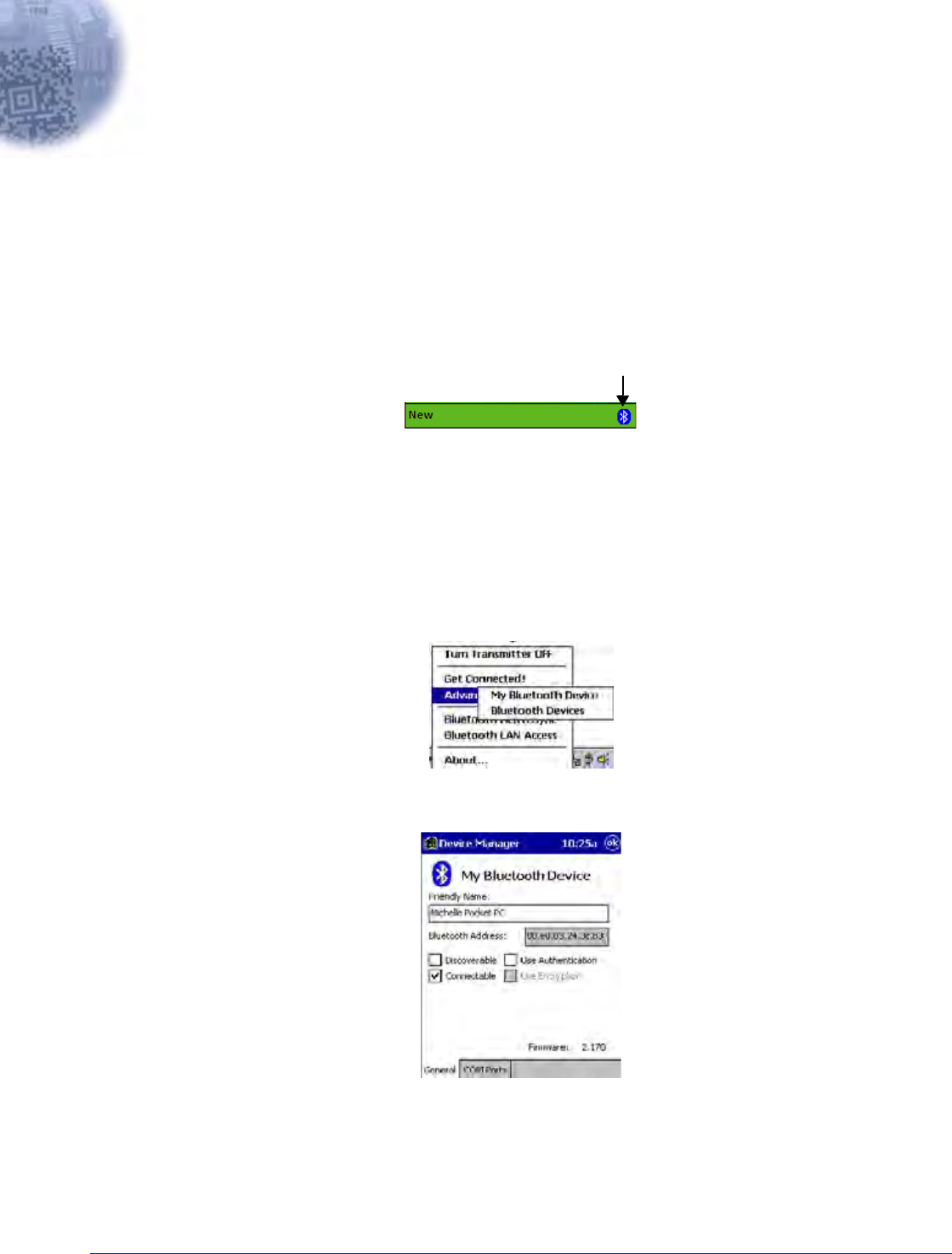
For example, the following graphic displays the authentication flow for a mobile user who wishes to create a virtual private
network with his home office.
By using the Client, the user can associate with a wireless network provided by a third party, in this case the ISP. We assume
that the company and the ISP have established a service relationship beforehand. When the ISP receives the user's credentials,
the ISP proxies the credentials to the company's AAA server, which returns a message telling the ISP to either accept or deny
the user access. This response is then propagated to the remote user.
Dynamic Session Specific Wireless Encryption Keys
There have been many published reports recently about the lack of security provided by the Wired Equivalent Privacy (WEP)
protocol. One of the problems with WEP is that the shared key used by the station and the access point is inherently static. That
is, this shared key will only change if it is manually reconfigured on both devices. The Client remedies this by supporting the
Transport Layer Security (TLS) protocol. TLS ensures that a new shared key is generated each time a station associates itself
with an access point. TLS has proven itself an excellent authentication and encryption protocol in commercial environments. The
Client also supports the MD5 and TTLS security protocols.
Additional Advantages of TTLS and PEAP
The Client provides the advantage of Tunneled TLS (TTLS) and PEAP support. These protocols provide the security of TLS
with greatly reduced administrative load. Security is enhanced by never passing user ID and password in the clear. No "real" user
ID or password is required in Phase 1. After the secure tunnel is established, Phase 2, user credentials are passed in safe,
encrypted form. To further enhance security, the WEP keys, which encrypt the data between the wireless card and the AP, may
be automatically changed on a per-session basis, limiting the time available to an unauthorized sniffer to crack the keys. By
limiting the session time (the reauthentication period), the keys can essentially be made uncrackable.
Administration is eased by greatly reduced certificate requirements in comparison to TLS. In TLS, each client must have a client
certificate to pass to the server, and a CA certificate with which to verify a server certificate, while the server must have a client
certificate from each user and CA certificates for each possible CA chain and its own server certificate. TTLS and PEAP require
only that a single server certificate be created for the server to present to the client, and that the client have a CA certificate to
verify the server. Because these are the same for each client on the network, they are easily managed, unlike TLS, where every
client certificate is unique. TTLS and PEAP thus provide the security of a TLS channel without the need for managers to distribute
and manage client certificates. Lastly, TTLS allows for the use of existing legacy authentication protocols. Administrators may
continue to use established authentication databases.
Cisco LEAP
The message exchange used by Cisco LEAP is proprietary. This protocol is not a standard EAP type, but is supported by the
Client through a licensing arrangement with Cisco.

Dolphin® 9500 Series Mobile Computer User’s Guide - Preliminary Rev (d) 12/17/04 7 - 41
Relative Merits of Authentication Protocols
MD5 is the least secure of the EAP protocols as it only does a one-way authentication, and does not support automatic
distribution and rotation of WEP keys, increasing the administrative burden of manual WEP key maintenance.
TLS, while the most secure EAP protocol, requires client certificates to be installed on each wireless client. Establishing and
maintaining this PKI infrastructure is normally a burden most administrators do not feel is worth the extra level of security gained.
TTLS and PEAP bypassed the certificate issue by tunneling TLS, and thus eliminating the need for a certificate on the client side.
PEAP supports only EAP-compliant authentication protocols within the tunnel structure, and is rapidly becoming the most widely
supported of the EAP methods. TTLS supports pre-EAP authentication protocols within the tunnel structure, and should be used
in those circumstances when pre-EAP interior protocols are desirable.
LEAP is a pre-EAP, Cisco-proprietary protocol, with many of the features of EAP protocols. Cisco controls the ability of other
vendors to implement this protocol, so it should be selected for use only when limited vendor choice for client, access-point, and
server products is not a concern.
Differences Between Protocols
Security Feature MD5
Challenge TLS TTLS PEAP LEAP
Client -side certificate required? No Yes No No No
Server-side certificate required? No Yes No Yes No
Dynamic WEP Re-keying No Yes Yes Yes Yes
Mutual or One-way Authentication? One-way Mutual Mutual Mutual Mutual
Support of non-EAP protocols within
a secure tunnel? N/A N/A Yes No N/A
Relative Deployment Complexity Simple Difficult Moderate Moderate Moderate
Relative Security Poorest Highest High High High

7 - 42 Dolphin® 9500 Series Mobile Computer User’s Guide - Preliminary Rev (d) 12/17/04
Dolphin® 9500 Series Mobile Computer User’s Guide - Preliminary Rev (d) 12/17/04 8 - 1
8
Wireless PAN Communications with Bluetooth
Overview
Dolphin 9500 Series terminals are available with a Bluetooth radio for WPAN (Wireless Personal Area Network) usage. When
the mobile computer is first initialized, the *.cab file and module for Bluetooth are installed.
Powering Up the Bluetooth Radio Driver
Before using the radio, make sure that the Bluetooth radio is powered up. When the radio driver is powered up, the Bluetooth
icon appears in the task tray on the Today screen.
Radios are powered up in the Radio Manager utility; see Powering Up a Radio on page 4-17.
Setting Up Your Bluetooth Card
Note: If you use the Get Connected! Wizard, which is recommended for normal usage, then this step is not necessary. This step
would be used to change the friendly name of your mobile computer.
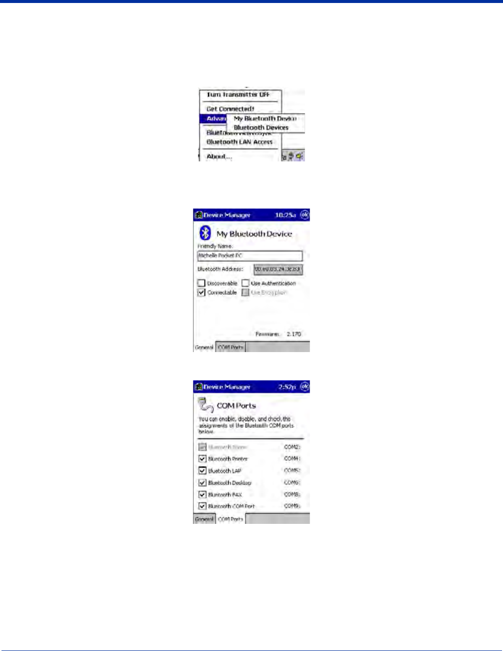
1. Tap the Bluetooth icon that appears in the task tray on the Today screen.
2. In the pop-up menu, select Advanced Features, then My Bluetooth Device. (If you installed OBEX, the menu also lists
Transfer via Bluetooth.)
3. In the My Bluetooth Device screen, you can modify the Friendly Name and make any desired configuration changes.
When done, tap OK.
• In normal phone connect operation, Discoverable mode is not needed and should be disabled.
• If you do enable Discoverable mode (e.g., for ActiveSync), note that it does not shut off by itself. To save power, remember
to disable it when not needed.
• Connectable, Use Authentication, and Use Encryption are also not required for printing or dial-up networking applications.
• Check Use Authentication to enable the Use Encryption option.
8 - 2 Dolphin® 9500 Series Mobile Computer User’s Guide - Preliminary Rev (d) 12/17/04
Assign COM Ports
Follow these steps to view and/or modify the Bluetooth COM ports. If you are not going to use the IrDA port, you can disable it
to free up a port for Bluetooth devices; see Using Infrared on page 6-6.
1. Tap on the Bluetooth icon on the Today screen. Select Advanced Features then My Bluetooth Device.
Note: If you installed OBEX, the menu also lists Transfer via Bluetooth.
2. The My Bluetooth Device screen appears. Tap on the COM Ports tab.
3. As needed, view and/or enable/disable the Bluetooth COM port assignments. Tap OK.
Note: The Bluetooth Phone port cannot be disabled. For more information about COM ports, see the Com Port Assignment
Table on page A-12.
Dolphin® 9500 Series Mobile Computer User’s Guide - Preliminary Rev (d) 12/17/04 8 - 3
Discover Bluetooth Device(s)
Follow these steps to discover other Bluetooth devices nearby, including non-phone devices. The Device Discovery Wizard is a
more detailed alternative to using the Bluetooth “Get Connected!” Wizard or Bluetooth ActiveSync or Bluetooth LAN Access
options. The Device Discovery Wizard allows you to discover any type of Bluetooth device.
1. If not open, launch the Bluetooth Devices folder. Tap on the Bluetooth icon on the Today screen. Select Advanced
Features then Bluetooth Devices.
2. In the Bluetooth Devices Folder, tap on the Device Discovery icon. Or you can tap on Tools. In the pop-up menu, select
Device Discovery.
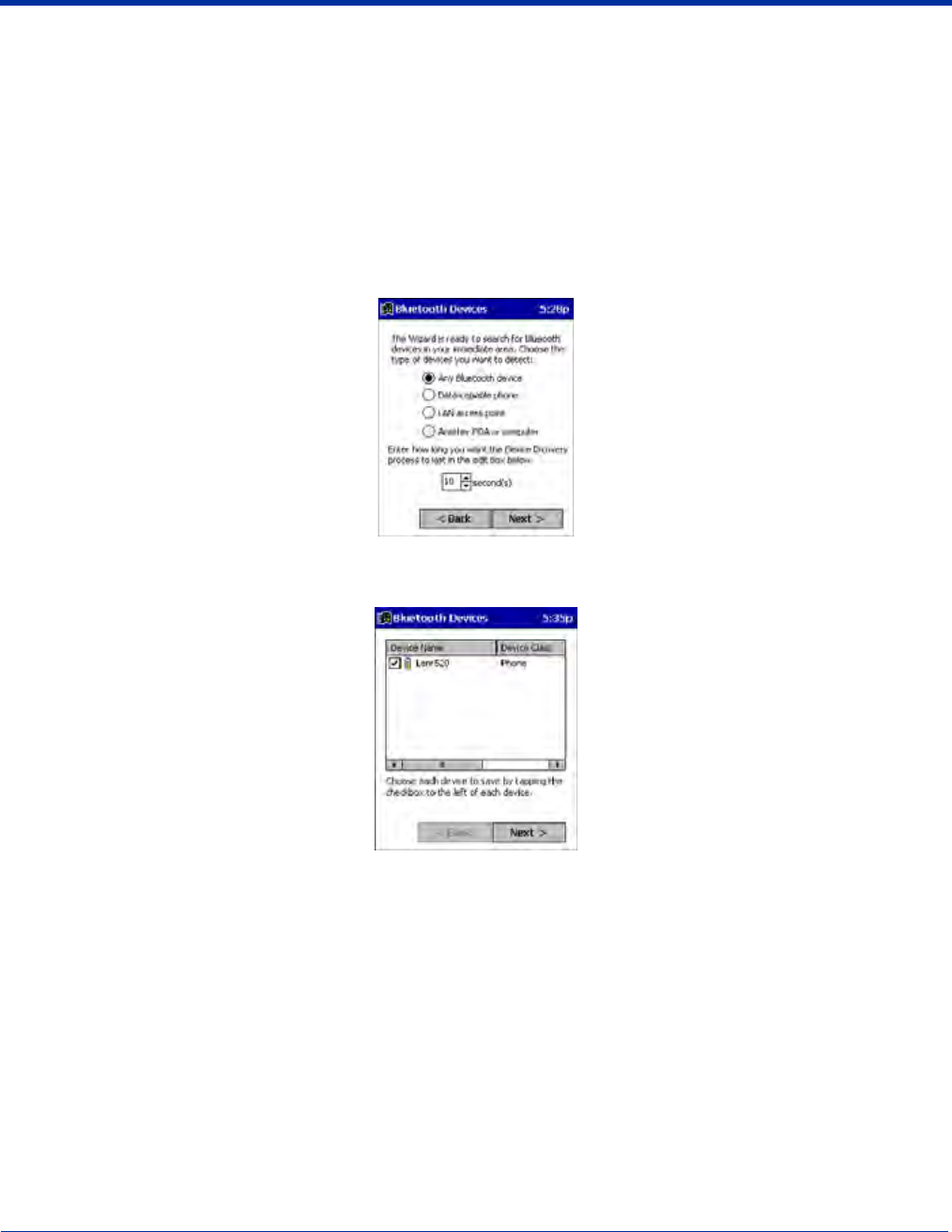
3. Follow the Bluetooth Device Discovery Wizard to search for Bluetooth devices nearby. When prompted, select the device
type you seek.
4. When the search is complete, a screen reports the discovered Bluetooth devices. Check the box next to any device you wish
to save information about, (i.e., any devices you wish to connect to). Tap Next.
5. A service discovery phase begins, 5-10 seconds per chosen device.
6. In the next screen, tap Finish.
Bond With Discovered Device(s)
Follow these steps to bond with an already discovered Bluetooth device. In most cases, bonding is for establishing secure
communications with a Bluetooth-enabled phone. This is a more detailed alternative to using the Bluetooth “Get Connected!
Wizard.”
Important!
• Do not try to bond with a Motorola Timeport 270C or Nokia 6310!
• Do not use this method to bond with a printer! The third-party printing software included on the installation CD also handles
bonding.
1. If not open, launch the Bluetooth Devices folder. Tap on the Bluetooth icon in the Today screen. Select Advanced
Features, then Bluetooth Devices.
8 - 4 Dolphin® 9500 Series Mobile Computer User’s Guide - Preliminary Rev (d) 12/17/04
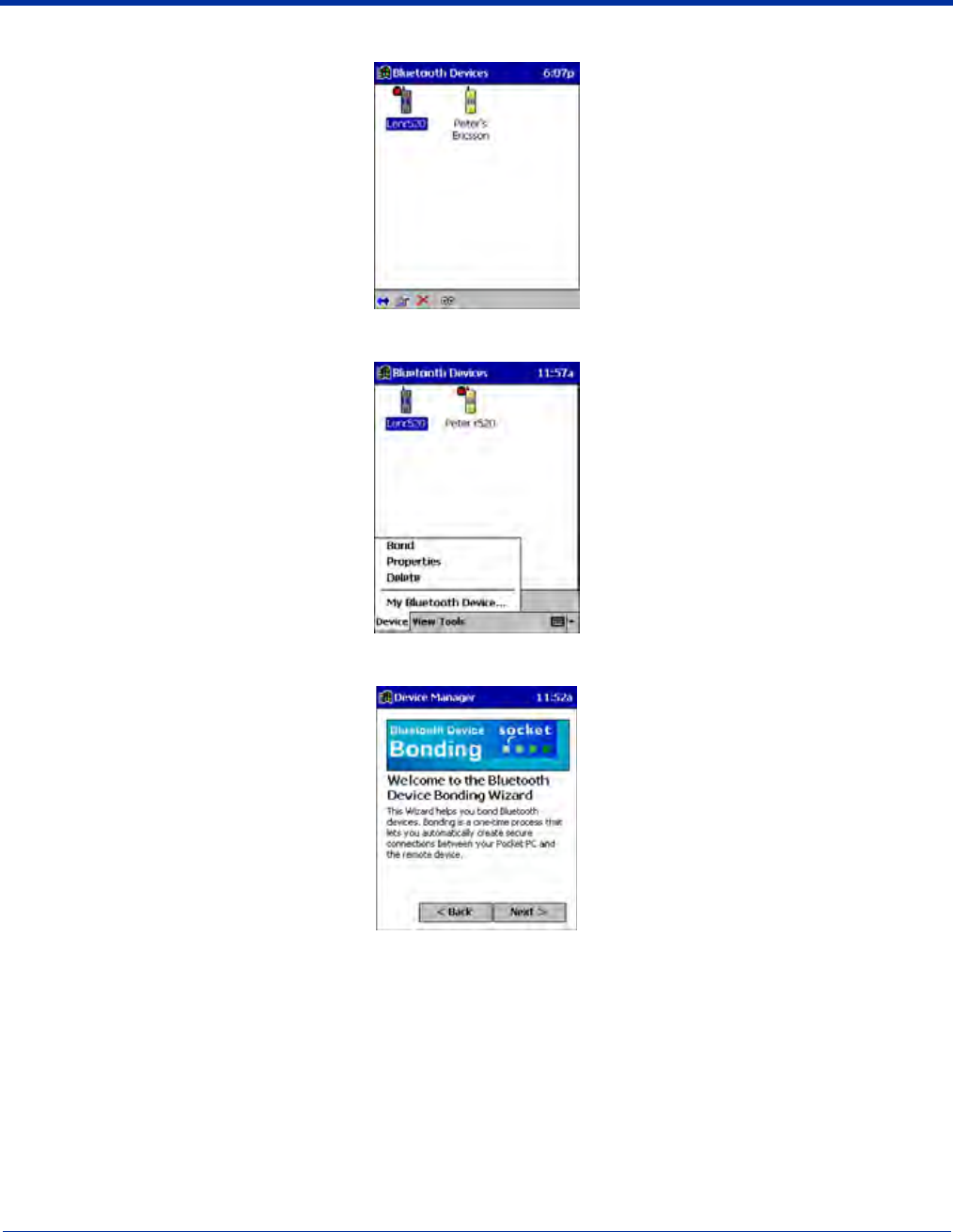
2. Tap and hold your stylus on the Bluetooth device you want to bond with. In the pop-up menu, select Bond.
3. Alternatively, after selecting a device, tap on the Bond icon. Or tap on Device, then select Bond.
4. The Bluetooth Device Bonding Wizard launches. Follow the wizard to bond with your selected device.
Dolphin® 9500 Series Mobile Computer User’s Guide - Preliminary Rev (d) 12/17/04 8 - 5
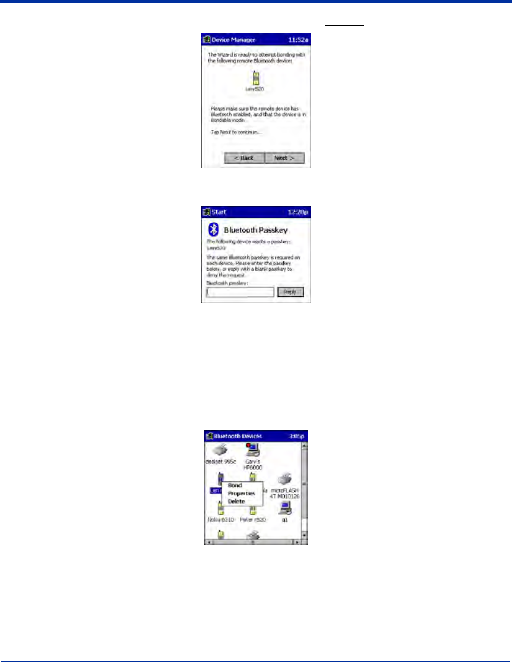
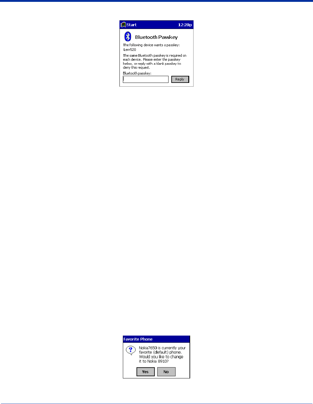
5. As prompted, make sure the Bluetooth device that you want to bond with is in Bondable mode.
6. If the remote device is set up to accept bonding, a Bluetooth Passkey screen appears. To continue bonding, enter the
correct passkey and tap Reply.
7. When you have successfully bonded with the other device, tap Finish.
View Device Properties
Follow these steps to view the properties of an already discovered device.
1. If not open, launch the Bluetooth Devices folder. Tap on the Bluetooth icon on the Today screen. Select Advanced
Features then Bluetooth Devices.
2. Select a device. Tap on the Properties icon, or tap on Device then select Properties. Alternatively, you can tap and hold
your stylus on the Bluetooth device you want to view information about. In the pop-up menu, select Properties.
8 - 6 Dolphin® 9500 Series Mobile Computer User’s Guide - Preliminary Rev (d) 12/17/04
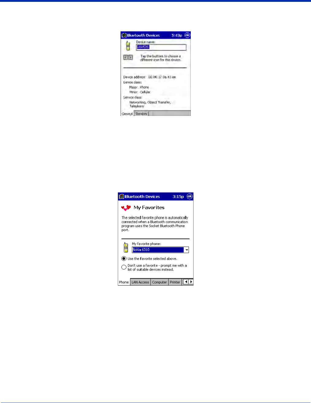
3. Use the General and Services screens to research device properties. If needed, assign a new device type icon by tapping
on the arrow buttons in the General screen. You can also use the Device name field to rename the device. When done, tap
OK for the setting to take effect.
Set Up Your Favorite Device
Follow these steps to set up default devices in the Bluetooth Devices folder. Please note that the Get Connected! Wizard
automatically assigns the favorite phone.
Complete these steps:
1. Tap on Tools and select My Favorites.
2. Tap on the tab for the type of device you would like to set a favorite for. If needed, use the arrow buttons to scroll and find the
tab you need.
Note: Tabs appears only for COM ports you have enabled. To enable a port, refer to the “Assign COM Ports” section earlier in
this chapter.
3. To select a favorite device, select Use the favorite selected above. In the drop-down list, select your device. Tap OK.
4. After setting a device as your favorite, its icon appears in the Bluetooth Devices folder with a heart next to it.
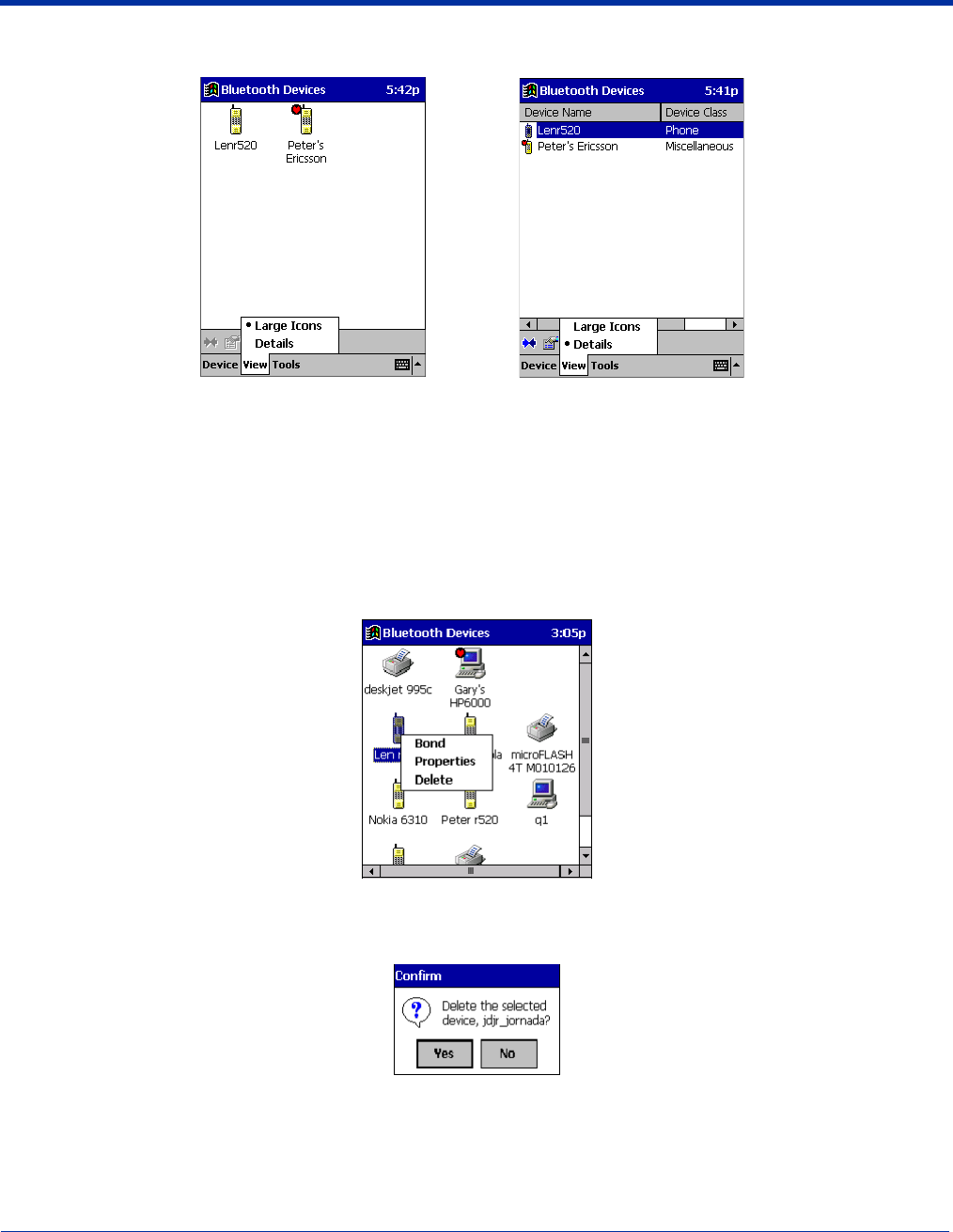
Change Views
You can switch between the Large Icons or Details views for the Bluetooth Devices folder.
1. In Bluetooth Devices, tap on View.
Dolphin® 9500 Series Mobile Computer User’s Guide - Preliminary Rev (d) 12/17/04 8 - 7
2. In the pop-up menu, choose between Large Icons or Details.
Note: In Details view, you can see the Device Class and scroll right to see the current Bonded status.
Delete a Device From the Folder
If you no longer plan to connect with it, you can delete a device from the Bluetooth Devices folder.
1. If not open, launch the Bluetooth Devices folder.
2. Tap and hold your stylus on the device you wish to delete. In the pop-up menu, select Delete.
3. Alternatively, after selecting a device, tap on the Delete icon. Or tap on Device then select Delete.
4. A Confirm screen appears. Tap Yes.
Large Icons Details
8 - 8 Dolphin® 9500 Series Mobile Computer User’s Guide - Preliminary Rev (d) 12/17/04
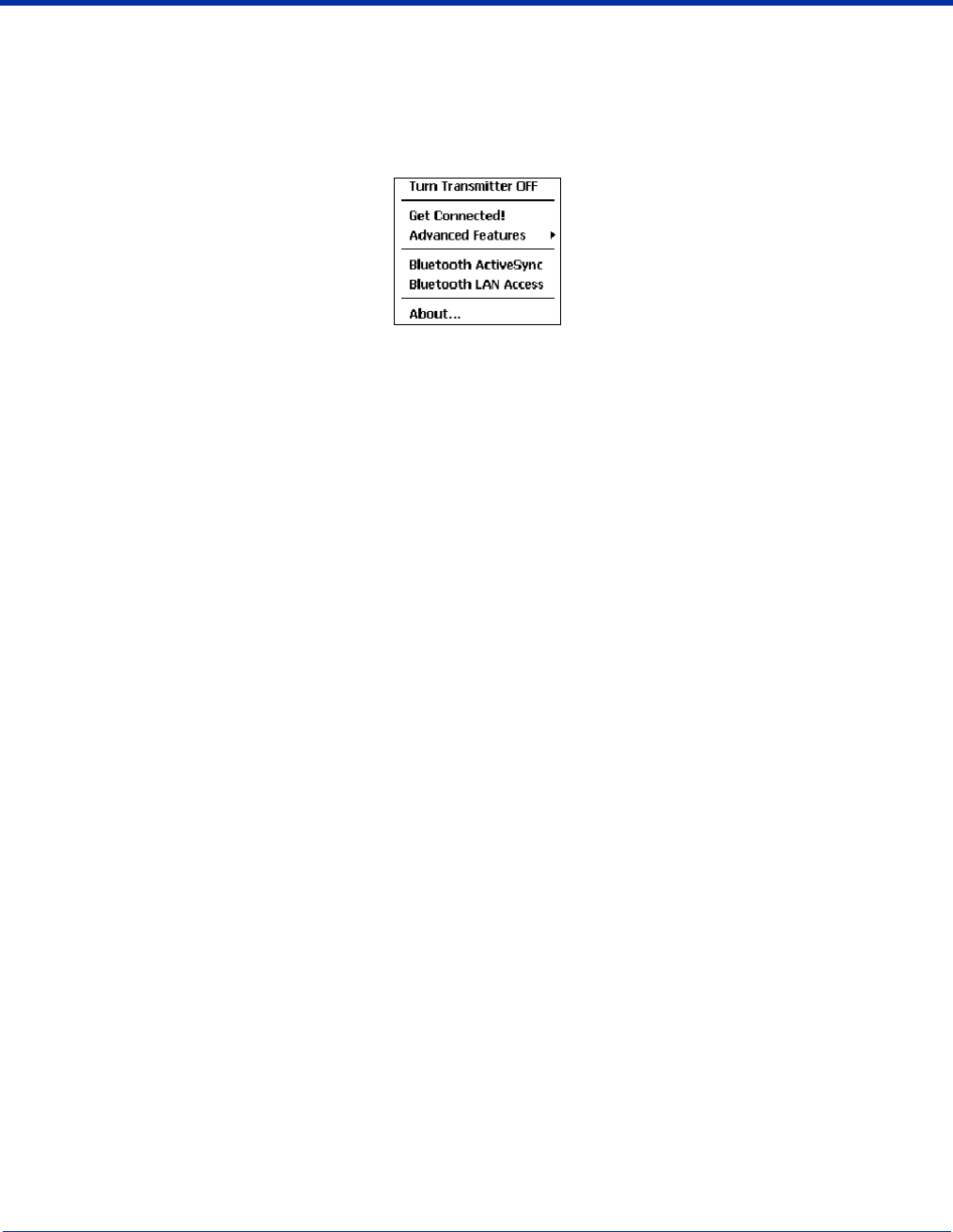
Turn Radio Transmitter ON/OFF
You may want to turn off the radio transmitter to save power or if you are entering an area with radio restrictions (e.g., an airplane).
1. The Bluetooth icon should appear in the task tray on the Today screen. Tap on the icon.
2. In the pop-up menu, select Turn Transmitter OFF.
3. The Bluetooth Card radio transmitter shuts off. The Bluetooth icon in the task tray becomes gray, as well as relevant menu
options (e.g., Get Connected!).
4. To turn the radio transmitter back on, tap on the gray Bluetooth icon. In the pop-up-menu, select Turn Transmitter ON.
Dolphin® 9500 Series Mobile Computer User’s Guide - Preliminary Rev (d) 12/17/04 8 - 9
Bluetooth ActiveSync
This section explains how to use the Bluetooth ActiveSync feature. It helps you quickly and easily ActiveSync to a notebook or
desktop computer with ActiveSync v3.x installed.
1. Tap on the Bluetooth icon. In the pop-up menu, select Bluetooth ActiveSync.
2. The next screens varies depending on if your Bluetooth Devices folder contains any computers, and if one is chosen as your
favorite. Please refer to the appropriate scenario:
SCENARIO #1: Your Bluetooth Devices folder contains a favorite desktop computer.
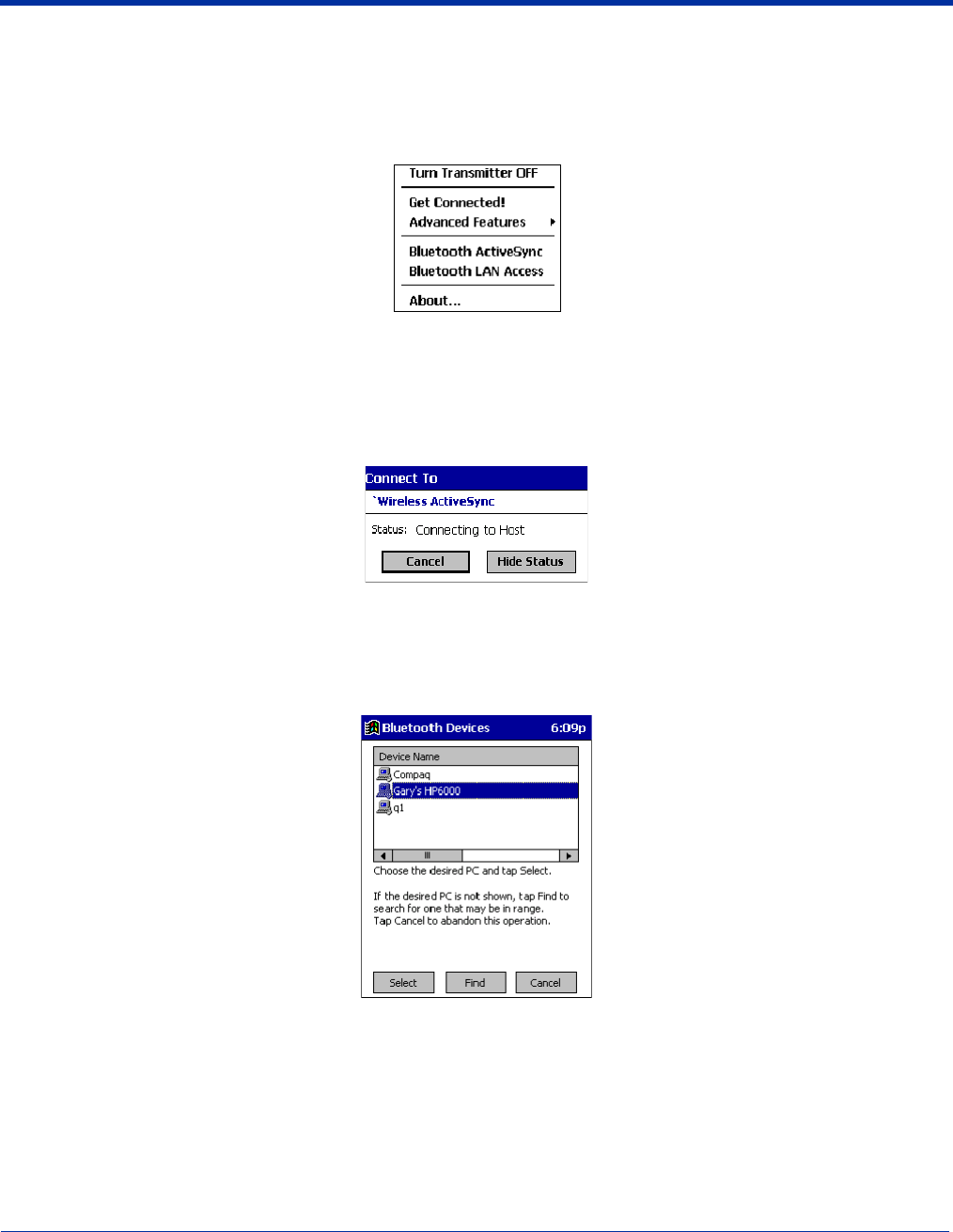
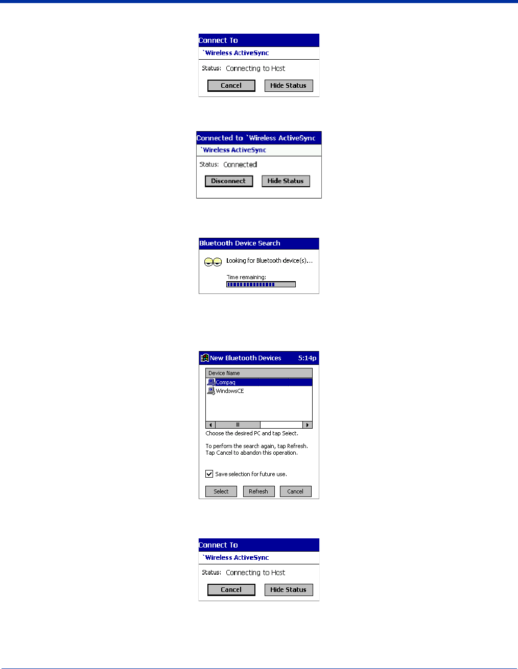
(a) When you tap Bluetooth ActiveSync, your mobile computer automatically tries to connect to your favorite computer.
(b) The Connect To screen appears, reporting that it is trying to connect to Wireless ActiveSync.
(c) After a successful connection is made, the status screen reports Connected. Now you are ready to synchronize files, if
desired.
SCENARIO #2: Your Bluetooth Devices folder contains no favorite desktop computer.
(a) When you tap on Bluetooth ActiveSync, a screen appears that allows you to choose which computer to connect to in
your Bluetooth Devices folder. Choose a computer from the list and tap Select, or tap Find to search for another computer.
Note: If the computer you want to connect to is not listed, tap Find to begin a search. Proceed as described in Scenario #3 on
page 8-10.
8 - 10 Dolphin® 9500 Series Mobile Computer User’s Guide - Preliminary Rev (d) 12/17/04
(b) Your mobile computer attempts to connect to your selected computer.
(c) After a successful connection is made, the status screen reports Connected. Now you are ready to synchronize files, if
desired.
SCENARIO #3: Your Bluetooth Devices folder contains no computers.
(a) When you tap on Bluetooth ActiveSync, a Bluetooth Device Search automatically begins.
Note: You can also start the device search by tapping Find in the Bluetooth Devices screen.
(b) After the search is complete, select the computer you wish to ActiveSync with and tap Select. If the computer is not listed,
make sure the computer is discoverable and tap Refresh to search again.
(c) After you tap Select, a service discovery phase begins.
(d) The Connect To screen appears, reporting that it is trying to connect to Wireless ActiveSync.
(e) After a successful connection is made, the status screen reports Connected. Now you are ready to synchronize, if desired.
Dolphin® 9500 Series Mobile Computer User’s Guide - Preliminary Rev (d) 12/17/04 8 - 11
Bluetooth LAN Access
This section explains how to use the Bluetooth LAN Access feature to quickly and easily connect to a Bluetooth-enabled LAN
access point.
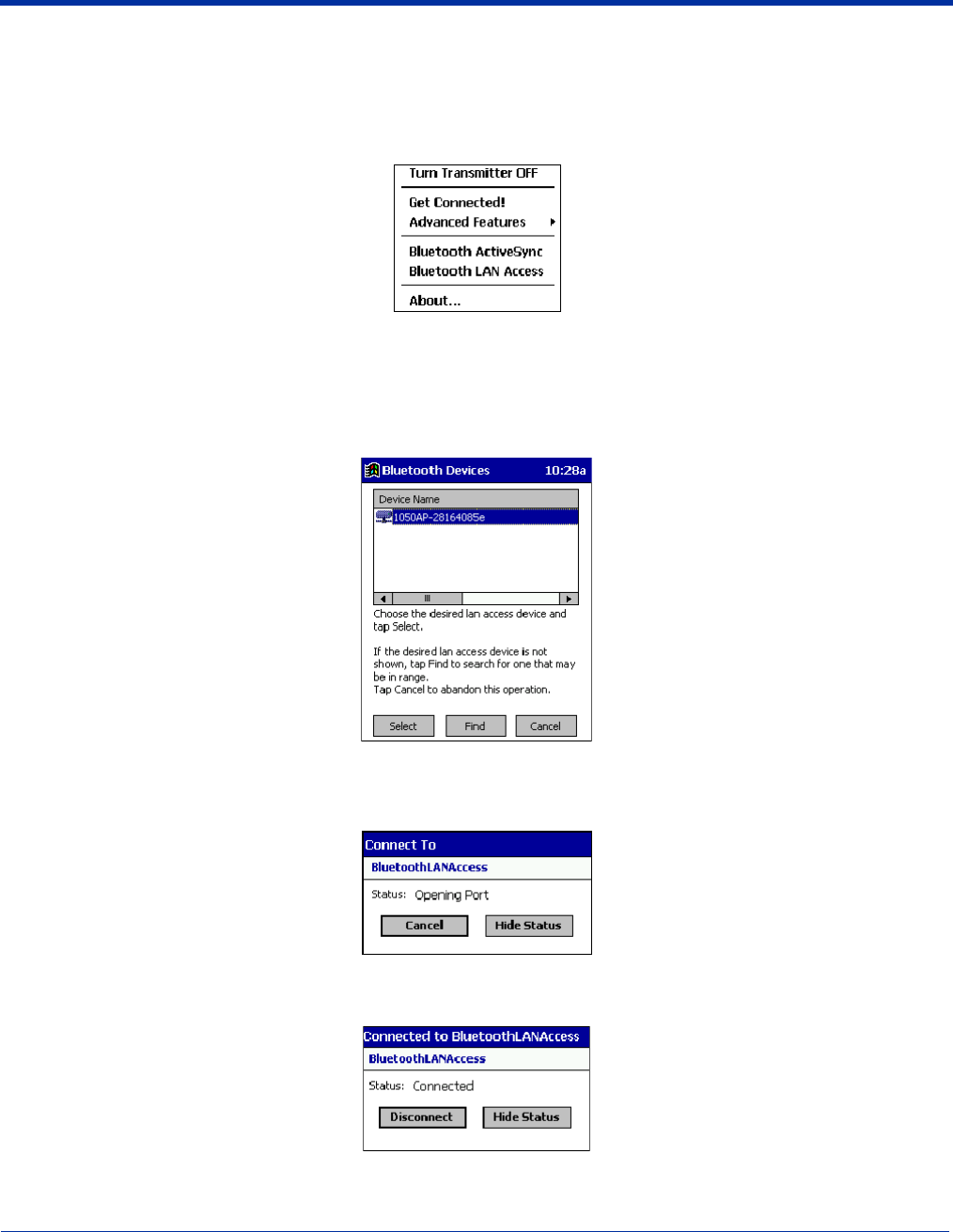
1. Tap on the Bluetooth icon. In the pop-up menu, select Bluetooth LAN Access.
2. The next screens varies depending on if your Bluetooth Devices folder contains any access points, and if one is chosen as
your favorite. Please refer to the appropriate scenario:
SCENARIO #1: Your Bluetooth Devices folder contains no favorite access point.
(a) When you tap Bluetooth LAN Access, a screen appears that allows you to choose which access point to connect to in
your Bluetooth Devices folder. Choose an access point from the list and tap Select.
Note: If your access point is not listed, tap Find and proceed as described in Scenario #3.
(b) Your mobile computer tries to connect to the selected access point.
(c) If your LAN requires a passkey, a screen appears asking for the passkey. Enter the passkey, then tap OK.
(d) After a successful connection is made, the status screen reports Connected.
(e) Now you are ready to access your LAN for Internet access, files, etc.
8 - 12 Dolphin® 9500 Series Mobile Computer User’s Guide - Preliminary Rev (d) 12/17/04
SCENARIO #2: Your Bluetooth Devices folder contains a favorite access point.
(a) When you tap Bluetooth LAN Access, your mobile computer automatically tries to connect with your favorite access
point.
(b) If your LAN requires a passkey, a screen appears, asking for the passkey. Enter the passkey, then tap OK.
(c) After a successful connection is made, the status screen reports Connected.
(d) Now you are ready to access your LAN for Internet access, files, etc.
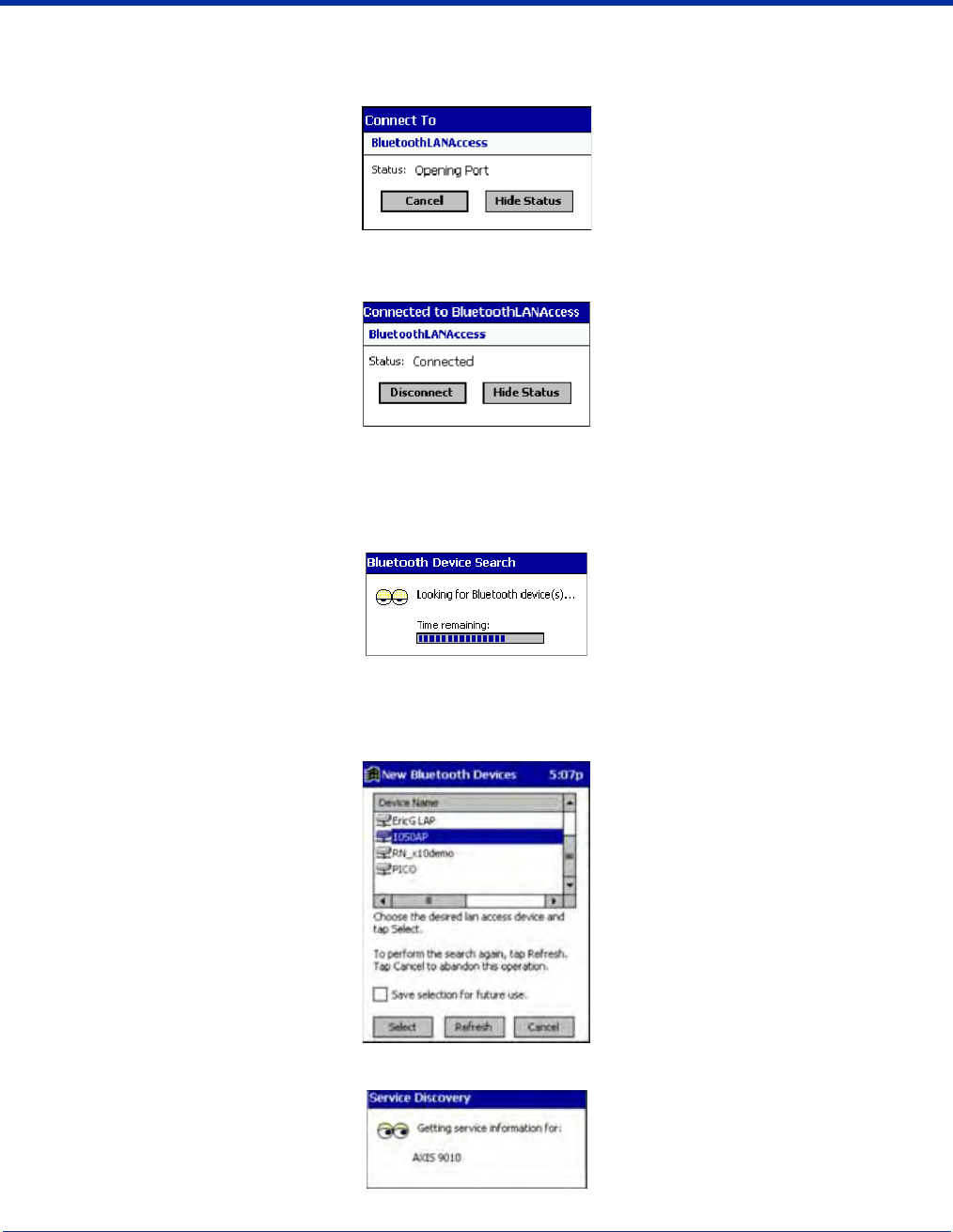
SCENARIO #3: Your Bluetooth Devices folder has no access points.
(a) When you tap Bluetooth LAN Access, the mobile computer automatically begins to search for new Bluetooth devices.
Note: You can also start the device search by tapping Find in the Bluetooth Devices screen. See Scenario #2 on page 8-9.
(b) After the search is complete, select the access point you wish to connect to. Tap Select. If the access point is not listed,
tap Refresh to search again.
(c) After you tap Select, a service discovery phase begins.
(d) If the LAN requires a Passkey, a screen appears, asking for the Passkey. Enter the passkey, then tap OK.

Dolphin® 9500 Series Mobile Computer User’s Guide - Preliminary Rev (d) 12/17/04 8 - 13
(e) After a successful connection is made, the screen reports Connected.
(f) Now you are ready to access your LAN for Internet access, files, etc.
8 - 14 Dolphin® 9500 Series Mobile Computer User’s Guide - Preliminary Rev (d) 12/17/04
OBEX
This section explains how to use the OBEX (object exchange) application to trade business cards, contacts or files with another
Bluetooth device that supports OBEX.
Bluetooth OBEX application supports five operations:
• Exchange Business Cards
• Send a Contact
• Send a File
• Browse Remote Device
• Receive Contact or File
• Enable File Sharing
The first four operations - exchange business cards, send a contact, send a file, and browse remote device - are client-oriented.
They involve initiating an object exchange.
The last two operations - receive contact or file and enable file sharing - are server-oriented. They involve accepting objects in
an exchange initiated by another Bluetooth device.
Exchange Business Cards
1. Make sure both Bluetooth devices have a business card assigned to them.
Note: If each device does not have a business card assigned to it, you cannot exchange business cards.
To assign a business card to your mobile computer, do the following:
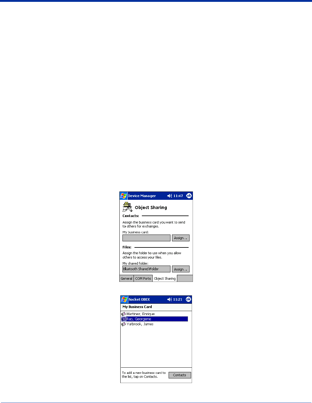
• Tap on the Bluetooth icon. In the pop-up menu, tap Advanced Features > My Bluetooth Device.
• Tap on the Object Sharing tab. Under My business card, tap Assign
• In the next screen, select your business card and tap OK. If your business card is not listed, tap Contacts to create one.
When you return to the Object Sharing screen, tap OK.
Dolphin® 9500 Series Mobile Computer User’s Guide - Preliminary Rev (d) 12/17/04 8 - 15
2. Make sure the other Bluetooth device is set up to receive a contact. The device must support the OBEX Object Push profile.
Note: If the other device is also using the Bluetooth Connection Kit, you can set it up to receive a contact by tapping the
Bluetooth icon. In the pop-up menu, tap Transfer via Bluetooth > Receive Contact or File.
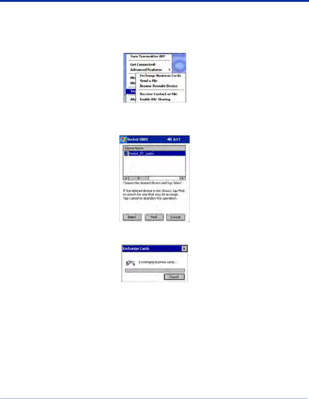
3. Now you are ready to exchange business cards. Tap on the Bluetooth icon. In the pop-up menu, tap Transfer via
Bluetooth > Exchange Business Cards.
4. If your mobile computer has no devices in the Bluetooth Devices Folder, then it begins to search for Bluetooth devices
nearby.
5. Select the Bluetooth device you wish to exchange business cards with. If the device is not listed, tap Find.
6. Your mobile computer begins to exchange business cards. After the exchange, the new business card should appear in your
Contacts list.
Send a Contact
1. Make sure the other Bluetooth device is set up to receive a contact. It must support the OBEX Object Push server profile.
Refer to the documentation that came with the device for instructions.
Note: If the other device is also using the Bluetooth Connection Kit, you can set it up to receive a contact by tapping the
Bluetooth icon. In the pop-up menu, tap Transfer via Bluetooth > Receive Contact or File.
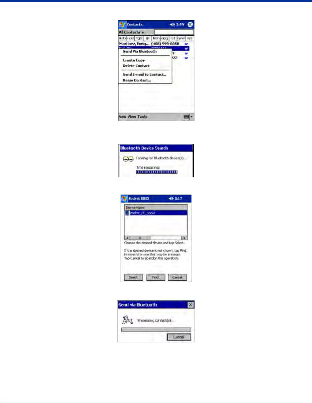
2. Now you are ready to send a contact. Go to your Contacts folder.
8 - 16 Dolphin® 9500 Series Mobile Computer User’s Guide - Preliminary Rev (d) 12/17/04
3. Tap and hold your stylus on the contact(s) you would like to send. In the pop-up menu, select Send Via Bluetooth.
4. If your mobile computer has no devices in the Bluetooth Devices Folder, then it begins to search for Bluetooth devices
nearby.
5. Select the Bluetooth device you wish to send the contact(s) to. If the desired device is not listed, tap Find.
6. Your mobile computer processes and send the contact(s).
Send a File
1. Make sure the other Bluetooth device is set up to receive a file. It must support the OBEX Object Push server profile. Refer to
the documentation that came with the device for instructions.
Note: If the other device is also using the Bluetooth Connection Kit, you can set it up to receive a file by tapping the Bluetooth
icon. In the pop-up menu, tap Transfer via Bluetooth > Receive Contact or File.
Dolphin® 9500 Series Mobile Computer User’s Guide - Preliminary Rev (d) 12/17/04 8 - 17
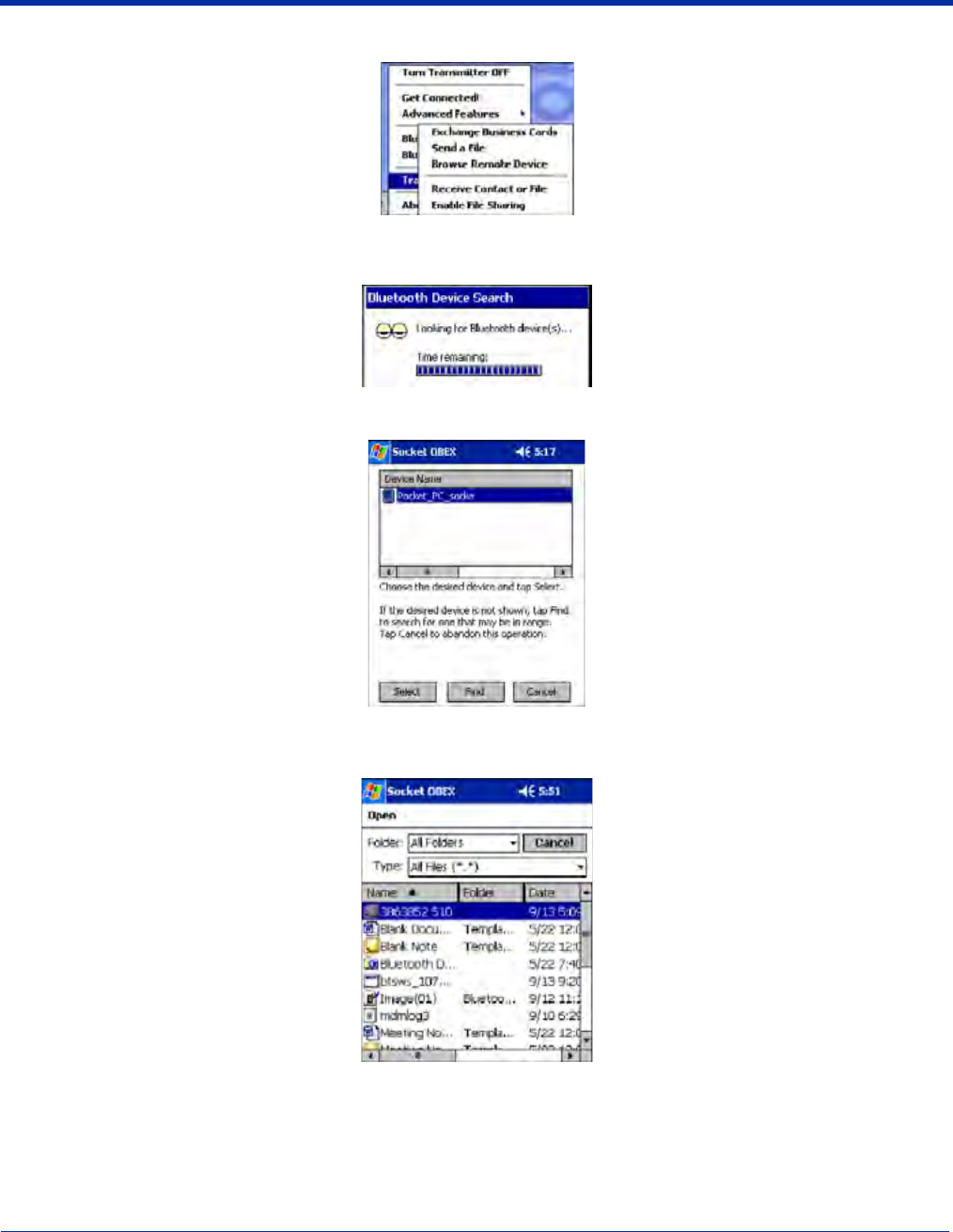
2. Now you are ready to send a file. Tap on the Bluetooth icon. In the pop-up menu, tap Transfer via Bluetooth > Send a File.
3. If your mobile computer has no devices in the Bluetooth Devices Folder, then it begins to search for Bluetooth devices
nearby.
4. Select the Bluetooth device you wish to send a file. If the desired device is not listed, tap Find.
5. In the next screen, tap on the file you wish to send. You can use the Folder and Type drop-down menus to search for your
file. Also, you can scroll horizontally to view the folder, date, size, type, and location of each file.
8 - 18 Dolphin® 9500 Series Mobile Computer User’s Guide - Preliminary Rev (d) 12/17/04
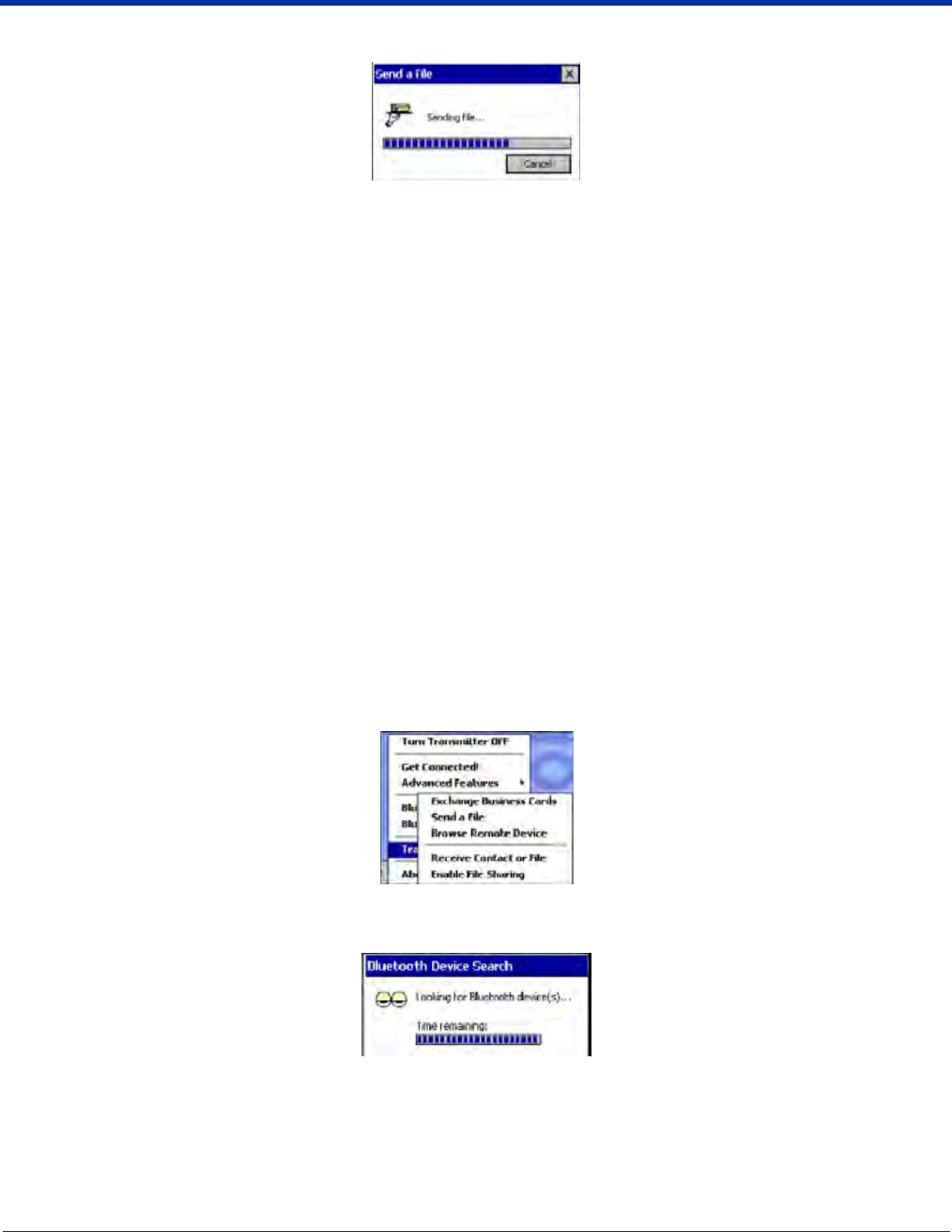
6. Your mobile computer sends the file.
Browse Remote Device
The Bluetooth File Explorer lets your mobile computer share files with another Bluetooth device. The other device must support
the OBEX File Transfer server profile.
This section covers the following file transfer operations:
• Prepare for file transfer
• Send/receive file(s) or folder(s)
• Create a folder
• Delete file(s) or folder(s)
• Refresh remote view
• Connect/disconnect
• Exit the program
Note: “Local device” refers to the mobile computer you are running the OBEX from. “Remote device” refers to the Bluetooth
device you are trying to transfer files with.
Prepare for File Transfer
1. Make sure the remote device has file sharing enabled. It must support the OBEX File Transfer server profile.
Note: If the other device is also using the Bluetooth Connection Kit, you can enable file sharing by tapping the Bluetooth icon.
In the pop-up menu, tap Transfer via Bluetooth > Enable File Sharing.
2. Now you are ready to browse the remote device. Tap on the Bluetooth icon. In the pop-up menu, tap Transfer via
Bluetooth > Browse Remote Device.
3. If your mobile computer has no devices in the Bluetooth Devices Folder that supports OBEX File Transfer, then it begins to
search for Bluetooth devices nearby.
Dolphin® 9500 Series Mobile Computer User’s Guide - Preliminary Rev (d) 12/17/04 8 - 19
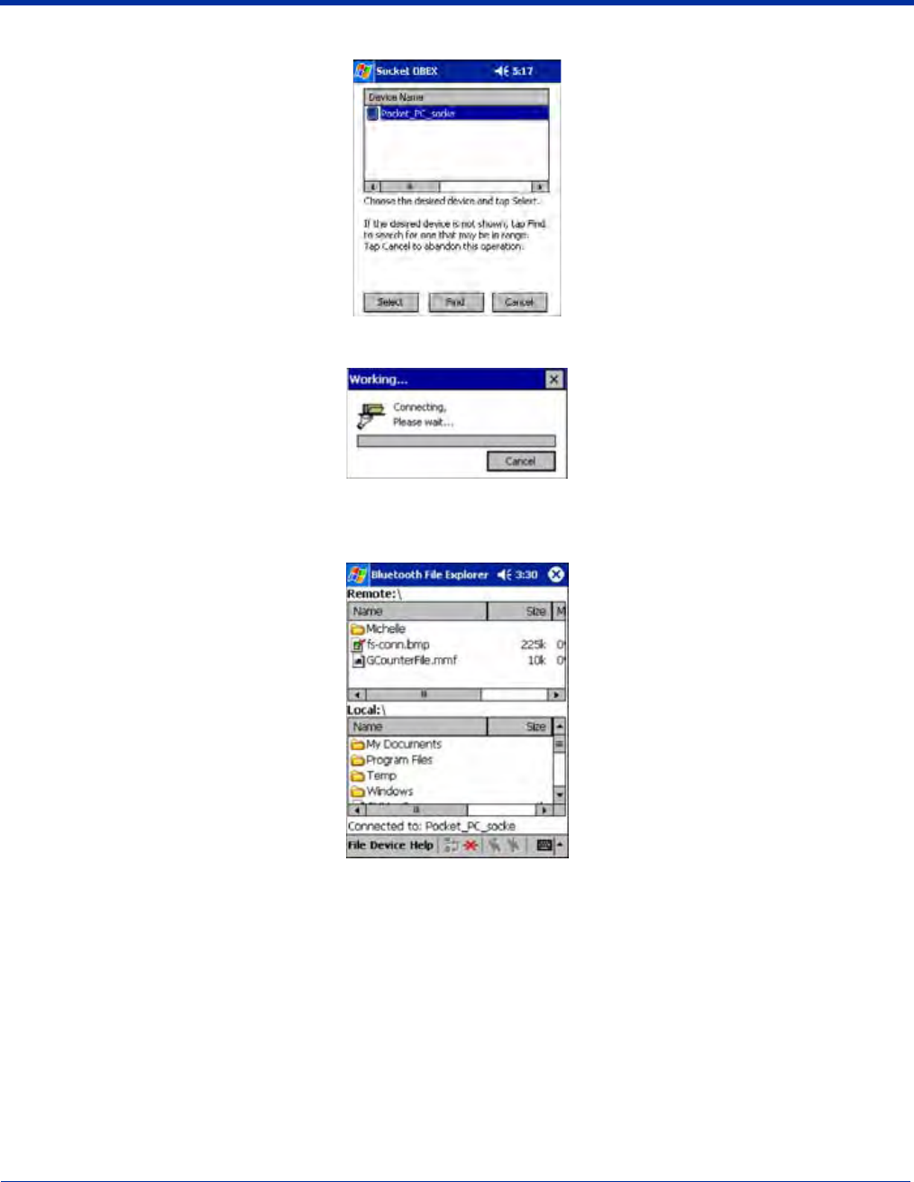
4. Select the Bluetooth device you wish to browse. If the desired device is not listed, tap Find.
5. Your mobile computer begins to establish a file sharing connection.
6. After the devices successfully connect, the Bluetooth File Explorer appears. Half of the screen shows contents of the remote
device, while the other half shows contents of your device (the local device). The very bottom of the screen reports the
connection status.
Send/Receive File(s) or Folder(s)
• Single-tap items to select them for transfer.
• Double-tap on a folders to open it and see its contents.
8 - 20 Dolphin® 9500 Series Mobile Computer User’s Guide - Preliminary Rev (d) 12/17/04
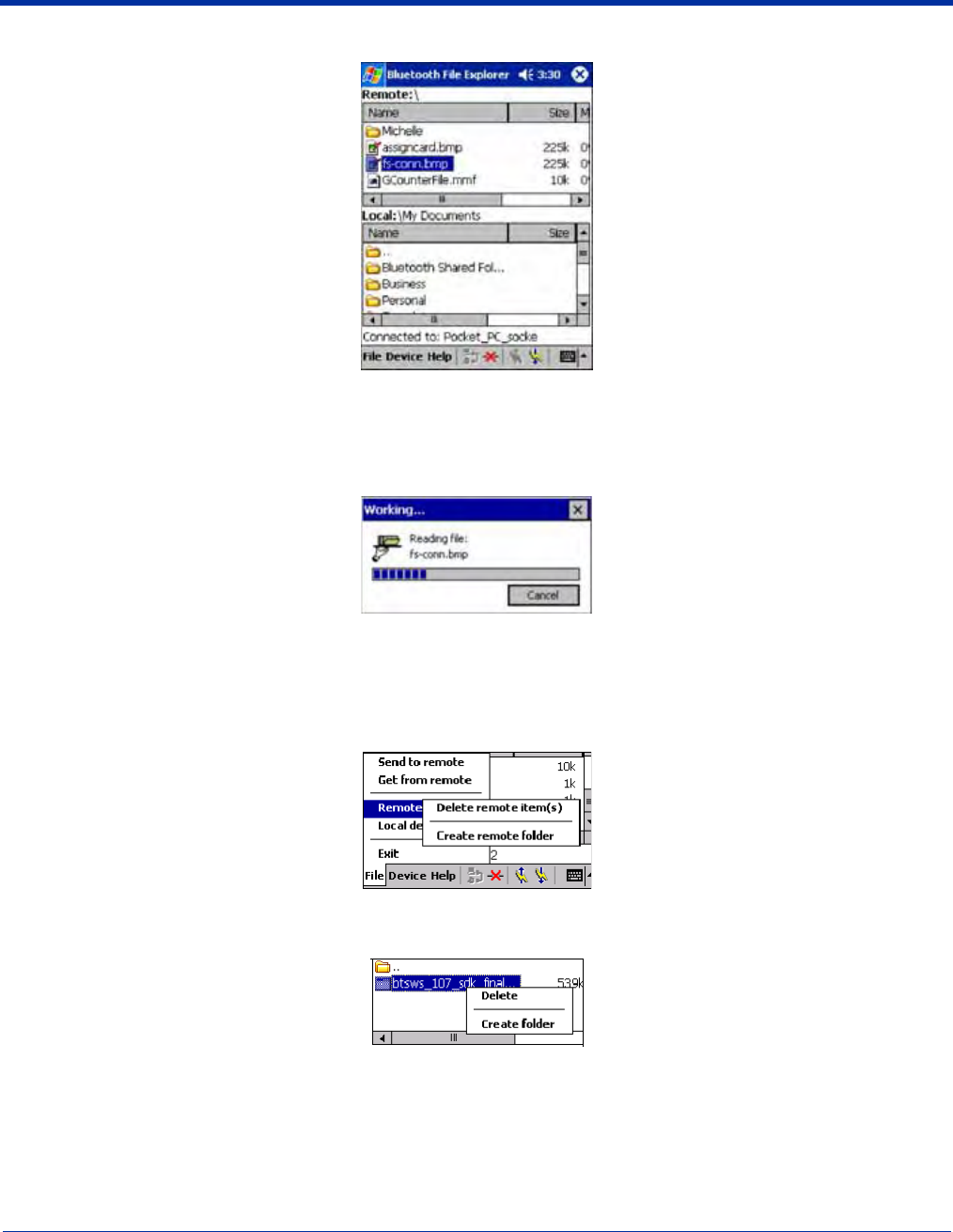
1. Select the file(s) or folder(s) that you wish to transfer. You can select items from only one device per transfer session.
2. There are two different ways to initiate the transfer:
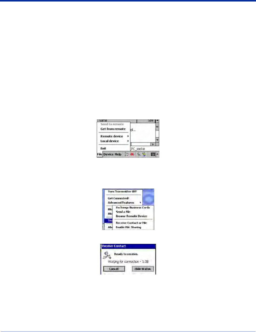
• Tap on the File menu. Select Send to remote or Get from remote, as applicable. The inappropriate option should be gray.
• Tap on the Send to remote icon or Get from remote icon, as applicable. The inappropriate icon should be gray.
3. A screen reports the status of the transfer.
4. After the transfer, a copy of each selected item should appear in the other device.
Create a Folder
1. Tap on the File menu. Select Remote device or Local device, wherever you want to create a folder, then tap Create
remote folder or Create local folder, as applicable.
2. You can also tap and hold your stylus on an item in either the remote or local device that you wish to put in a new folder. In
the pop-up menu, select Create folder.
Dolphin® 9500 Series Mobile Computer User’s Guide - Preliminary Rev (d) 12/17/04 8 - 21
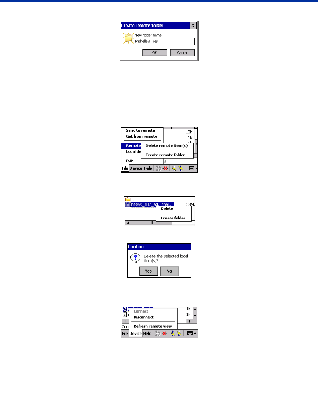
3. In the next screen, enter a name for your new folder. Tap OK.
4. The new folder should be listed under the appropriate device.
Delete File(s) or Folder(s)
1. Select item(s) that you wish to delete. You can only delete item(s) from one device at a time.
2. Tap on the File menu. Select Remote device or Local device, wherever the item(s) are located, then tap Delete remote
item(s) or Delete local item(s), as applicable.
3. Tap and hold your stylus an item in either the remote or local device that you wish to put in a new folder. In the pop-up menu,
select Delete folder.
4. In the Confirm screen, tap Yes.
Refresh Remote View
1. Tap on the Device menu. Select Refresh remote view.
2. Your local device begins to read the contents of the remote device.
3. After a few seconds, the contents view of the remote device is refreshed.
Connect/Disconnect
To connect to the remote device, do the following:
1. Make sure the remote device has file sharing enabled.
8 - 22 Dolphin® 9500 Series Mobile Computer User’s Guide - Preliminary Rev (d) 12/17/04
2. Start the connection process by either of two methods:
• Tap on the Device menu. Select Connect.
• Tap on the Connect icon.
3. In the next screen, select the device you wish to connect to. Tap Select. Your mobile computer attempts to connect to the
device selected.
To disconnect from the remote device, do the following:
1. Start the disconnection process by either of two methods:
• Tap on the Device menu. Select Disconnect.
• Tap on the Connect icon.
2. Your mobile computer disconnects from the remote device. Afterwards, no contents are listed for the remote device.
Exit Bluetooth File Explorer
To exit the Bluetooth File Explorer, tap File > Exit.
Receive Contact or File
1. Tap on the Bluetooth icon. In the pop-up menu, tap Transfer via Bluetooth > Receive Contact or File.
2. The Receive Contact or File status screen appears. Your mobile computer waits two minutes for the contact or file.
3. After successfully connecting to the remote device, the screen reports Connected then disappear. The new contact or file
should now be on your device.
4. If two minutes passes before you receive the item, tap Wait Again.
5. After you receive the file or contact, the “Receive Contact or File” feature is automatically disabled.

Dolphin® 9500 Series Mobile Computer User’s Guide - Preliminary Rev (d) 12/17/04 8 - 23
Enable File Sharing
1. Tap on the Bluetooth icon. In the pop-up menu, tap Transfer via Bluetooth > Enable File Sharing.
2. The Enable File Sharing status screen appears. Your mobile computer waits two minutes for the remote device to connect.
3. After successfully connecting to the remote device, the screen report Connected.
4. If two minutes passes before you connect, tap Wait Again.
5. File sharing is enabled until you end it by tapping Cancel.
8 - 24 Dolphin® 9500 Series Mobile Computer User’s Guide - Preliminary Rev (d) 12/17/04
Using the Dialer
This section explains how to assign a dialing prefix and use the Dialer to dial a number directly from your Contacts list. The Dialer
makes it quick and easy to perform dial-up networking.
Note: The Dialer has been verified to work with Nokia and Ericcson phones and is known not to work with the Motorola 270c,
NTT Docomo Paldio 633S or Sony au C413S phone. Results may vary with other phones that are not listed as being supported
by the Bluetooth system.
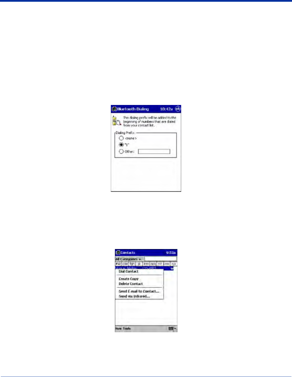
Assign a Dialing Prefix
If you have not already assigned a dialing prefix during the install process, you can do so by following these steps:
1. Go to Start > Settings > System tab. Tap on Dialer.
2. Select the appropriate Dialing Prefix, then tap OK.
Using the Dialer
1. To use the dialer, the mobile computer must already be connected to the Bluetooth phone. You can use the Get Connected!
Wizard to do this. Also, the Bluetooth phone must be selected as your favorite.
2. Go to Start > Contacts.
3. Tap and hold your stylus on the contact you wish to dial to. In the pop-up menu, select Dial Contact. Alternatively, you can
tap on Tools and select Dial Contact.
Dolphin® 9500 Series Mobile Computer User’s Guide - Preliminary Rev (d) 12/17/04 8 - 25
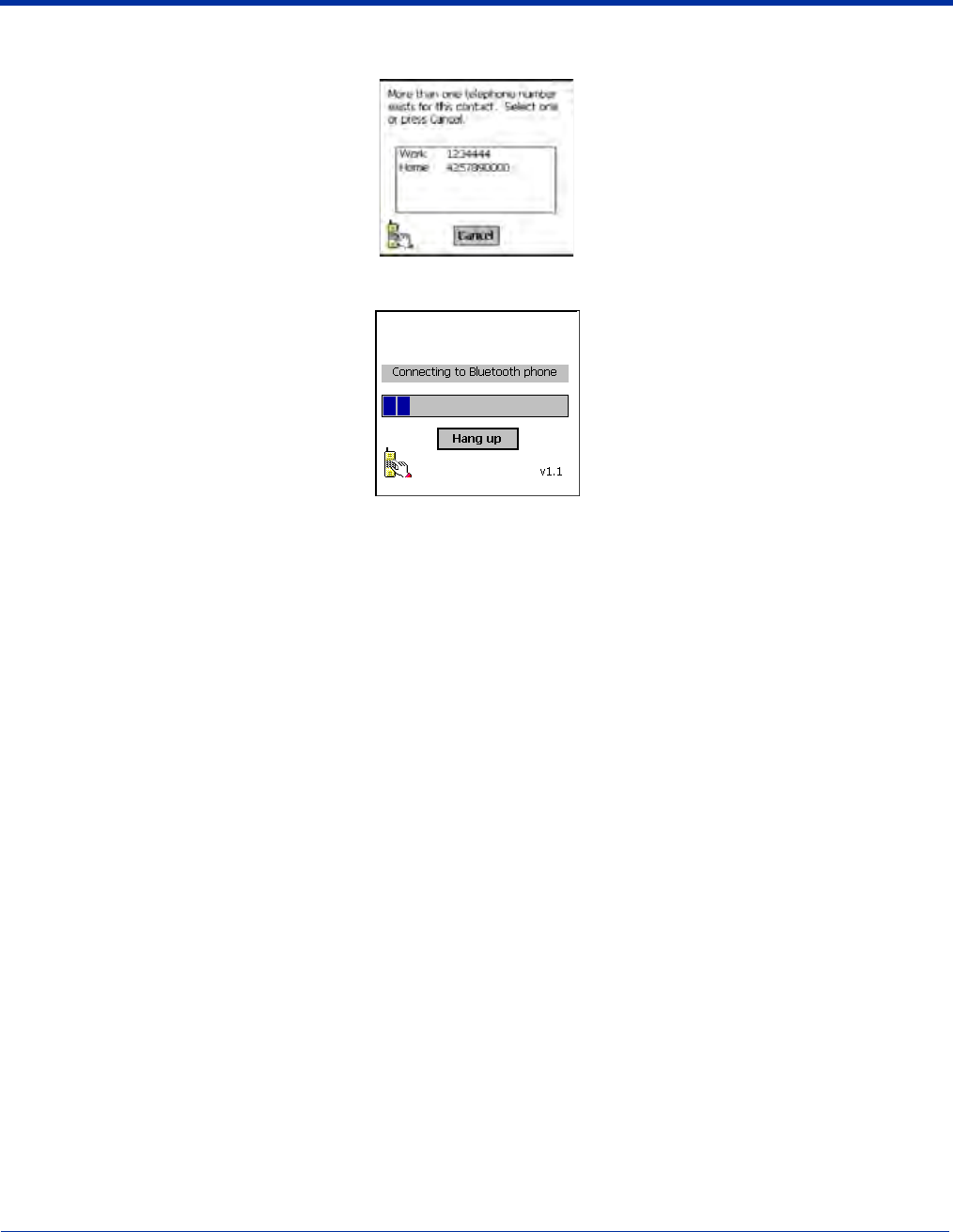
4. If you have multiple phone numbers for a contact, a screen appears listing them, including any dialing prefix you may have
assigned. Select the phone number you wish to dial.
5. Your mobile computer connects to your phone and begins dialing.
The Dialer can dial a phone number containing any of the following non-numeric characters:
* # + . / ! @ - \ space A B C D T P W
The following string can also be included in a phone number: (',')
The Dialer cannot dial a phone number containing non-numeric characters other than those listed above. Hand Held Products
recommends that you follow the standard Microsoft Outlook format for phone numbers.
8 - 26 Dolphin® 9500 Series Mobile Computer User’s Guide - Preliminary Rev (d) 12/17/04
Get Connected Wizard
The Get Connected! Wizard guides you through a one-time setup process that prepares the mobile computer and phone for
Bluetooth connections. The wizard varies depending on what phone you want to connect to.
Ericcson, Nokia 6210, NTT DoCoMo, Sony Phones
1. Tap on the Bluetooth task tray icon. In the pop-up menu, select Get Connected!
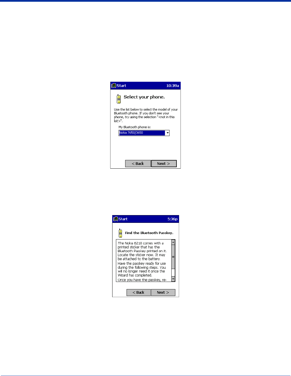
2. Follow the Bluetooth “Get Connected!” Wizard. In the second screen, use the drop-down list to select your Bluetooth phone.
The wizard provides tailored instructions based on your selection.
3. Follow the next screen(s) to prepare your specific phone for Bluetooth connections. You may need to do 1, 2 or all of the
following steps:
(a) Naming your Bluetooth phone
(b) Setting your Bluetooth phone in Discoverable mode
(c) Preparing your Bluetooth passkey.
Dolphin® 9500 Series Mobile Computer User’s Guide - Preliminary Rev (d) 12/17/04 8 - 27
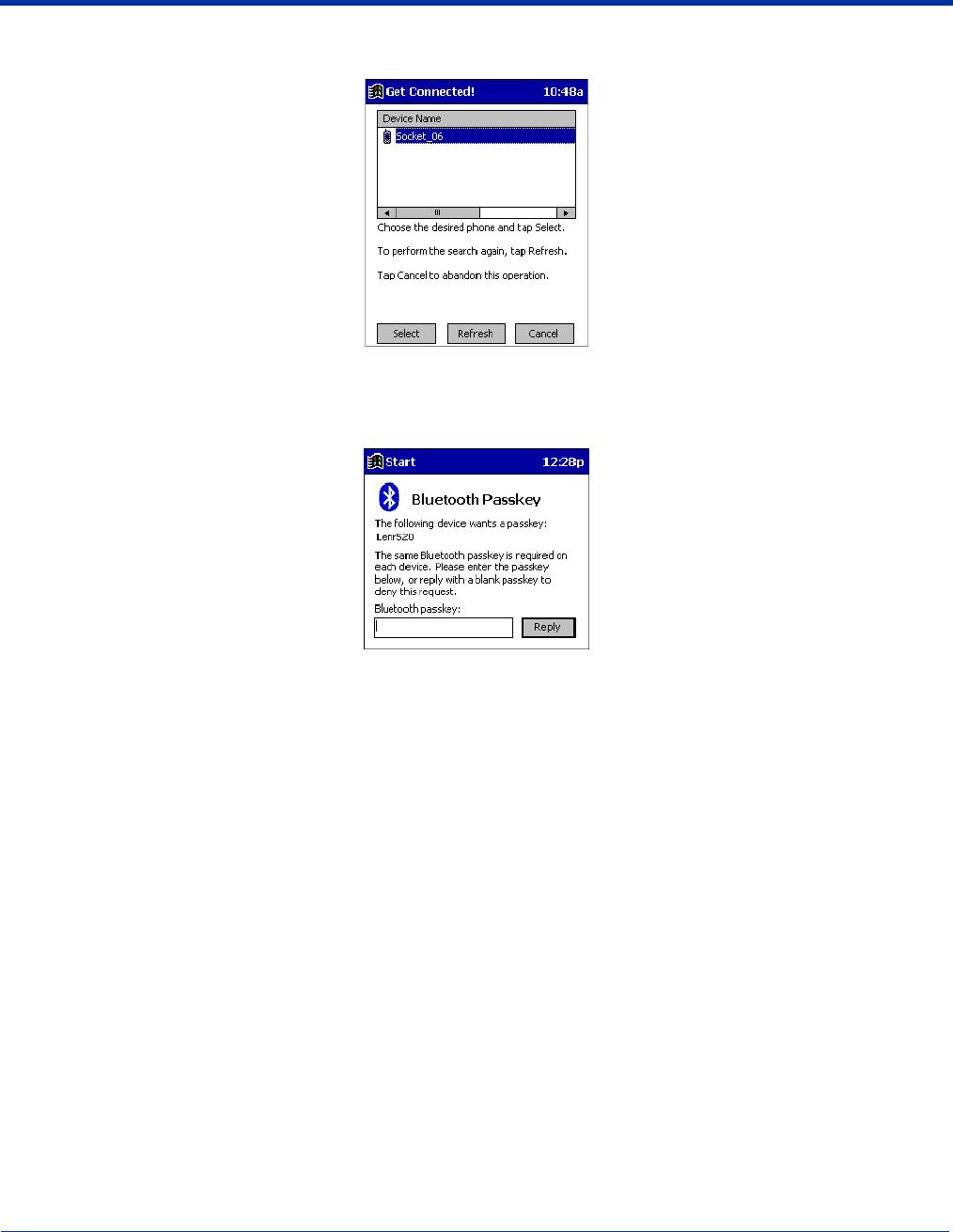
4. When the search is complete, a list of the discovered Bluetooth phones appears. Choose the phone you wish to connect to,
and tap Select. A service discovery phase begins, about 5-10 seconds.
5. As prompted in the next screen, prepare your phone for bonding. For instructions on setting your phone to “Bondable” or
“Pairable” mode, refer to your phone manual. Have your passkey ready, then tap Next>.
6. In the next screen, enter the passkey. Tap Reply.
7. The mobile phone may then either automatically accept the passkey or ask you to enter one. If prompted for a passkey, use
the same one you entered on the mobile computer.
Ericsson T68/T68i only: When the phone asks you if you want to bond, select 2: Add to paired devices. Do not tap ACCEPT.
8. Tap Finish. After successfully connecting, the phone appears in the Bluetooth Devices folder. On the Today screen, the
Bluetooth icon blinks. You do not need to run the Get Connected! Wizard again unless you plan to switch between different
phones.
Note: You may also switch between different phones by assigning a new “favorite phone” in the Bluetooth Devices folder.
Motorola Timeport 270C, Nokia 3650/6310/7650/8910/8910i
1. Tap on the Bluetooth task tray icon. In the pop-up menu, select Get Connected!
2. Follow the Bluetooth “Get Connected!” Wizard. In the second screen, use the drop-down list to select your Bluetooth phone.
The wizard provides tailored instructions for your phone.
Note: The screens below are for the Nokia 7650.
3. As directed on the next two screens, assign the phone a unique name, set the phone to Discoverable mode, and tap Next.
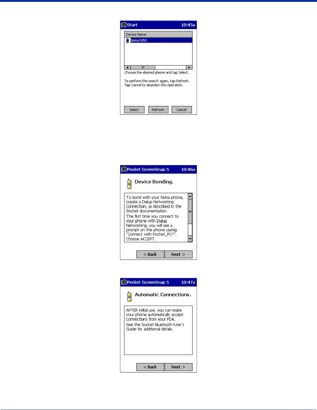
8 - 28 Dolphin® 9500 Series Mobile Computer User’s Guide - Preliminary Rev (d) 12/17/04
4. The mobile computer searches for the phone. When the search is over, a list of the discovered Bluetooth phones appears.
5. Choose the phone you want to connect to, and tap Select. A service discovery phase begins, about 5-10 seconds.
6. The next two screens describe procedures you complete outside of the wizard. Read through each screen but do not
complete the described procedures until you exit the wizard.
Bonding with your phone - This must be completed to establish the Bluetooth connection and involves dial-up
networking.
Automatic Connections - This procedure is optional but makes future Bluetooth connections more convenient.
7. Continue to the last screen of the wizard and tap Finish. Now proceed to STEP 6 to complete the bonding process and, if
desired, set up automatic connections.
Dolphin® 9500 Series Mobile Computer User’s Guide - Preliminary Rev (d) 12/17/04 8 - 29
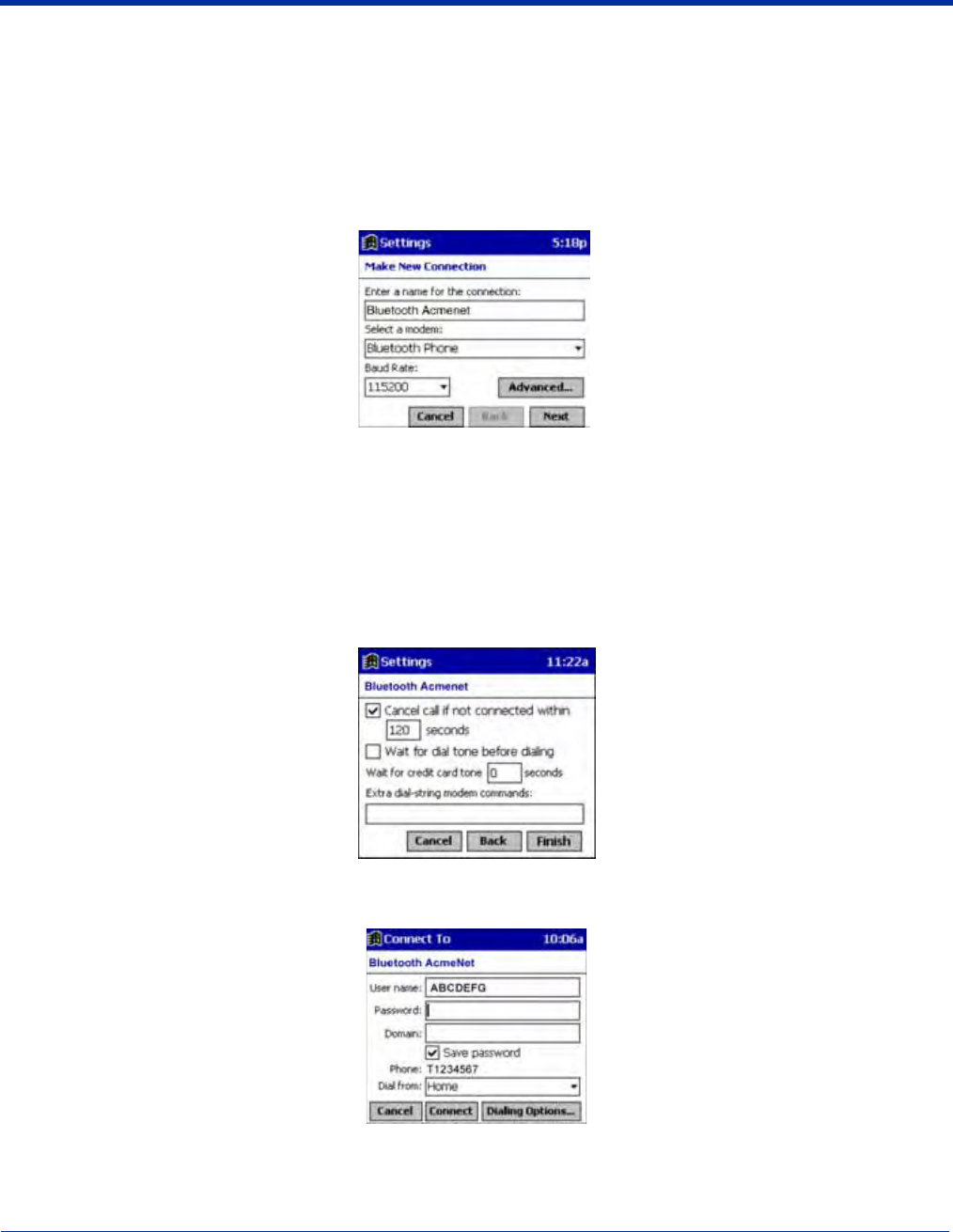
Dial Up to Your Network
Complete the following steps to create a new Bluetooth internet connection. Before setting up dial-up networking, prepare
yourself with dial-up information and other necessary settings from your office network or ISP.
Note: For more information about modem connections, see Creating an External Modem Connection to an ISP on page 5-16.
1. Go to Start > Settings > Connections tab > Connections.
2. In the top field, select Internet Settings and tap Modify. Then, tap New.
3. Enter a name for the connection. Remember what you name the connection. In the future, you will need to select it to start
the connection.
For the modem, select Bluetooth Phone.
For the Baud Rate, select 115200.
If you want to configure Port Settings, TCP/IP, or Name Server settings, navigate to the setting and tap Advanced.
4. Tap Next.
5. In the Phone number field, enter the dial-up number. Tap Next.
6. Uncheck Wait for dial tone before dialing. Tap Finish.
7. Now you are ready to start the connection. In the Connections screen, under Internet Settings, tap Connect. In Network Log
On, verify the dialing settings. Tap OK.
ONLY FOR MOTOROLA TIMEPORT 270C OR NOKIA 3650/6310/7650/8910/8910i:
a) After you tap Connect for the first time, the phone displays a message asking if you want to bond. On Motorola, enter
GRANT; on Nokia, enter ACCEPT.
8 - 30 Dolphin® 9500 Series Mobile Computer User’s Guide - Preliminary Rev (d) 12/17/04
b) Make up a 4-16 digit passkey, enter it on the phone, then enter it on the Dolphin terminal.
Note: The Bluetooth icon on the Today screen blinks to indicate a connection.
c) After successfully bonding, you can set up the phone to automatically connect to your Dolphin terminal without requiring a
passkey.
Automatic Connections for Motorola Timeport 270C:
• On the phone, press MENU.
• Scroll to Settings, then press SELECT.
• Scroll to Connection, then press ON.
• On Bluetooth Link, press SELECT.
• Scroll to Devices, then press SELECT.
• Choose your mobile computer, then press EDIT.
• Scroll to Access:Ask, then press CHANGE.
• Scroll to Automatic, then press SELECT. Press DONE.
Automatic Connections for Nokia 3650/7650:
• On the phone, press MENU.
• Scroll to Connectivity, then press OPTIONS.
• The Open option should be highlighted. Press SELECT.
• The Bluetooth option should be highlighted. Press OPTIONS.
• The Open option should be highlighted. Press SELECT.
• Scroll to the right tab to access the Paired devices list. Highlight your mobile computer, then press OPTIONS.
• Scroll to Set as authorized, then press SELECT.
• In the confirmation screen, press YES.
Automatic Connections for Nokia 6310/8910/8910i:
• On the phone, press MENU.
• Scroll to 10 Bluetooth, then press SELECT.
• Scroll to 4 View Paired Devices, then press SELECT.
• Highlight the Dolphin terminal, then press OPTIONS.
• Scroll to 3 Request Connection Authorization, then press NO.
To use a different Bluetooth phone for dial-up networking, you can use the same connection setup, but you must make the new
phone your favorite. Just run the Get Connected! Wizard again, select the new phone, and make it your new Favorite when
prompted.

Dolphin® 9500 Series Mobile Computer User’s Guide - Preliminary Rev (d) 12/17/04 9 - 1
9
Wireless WAN Communications with GSM/GPRS
Overview
Dolphin 9500 terminals are the only terminals in the Dolphin 9500 Series can be configured with Wireless Wide Area Network
(WWAN) via an integrated Siemens® GSM/GPRS tri-band radio module.
Note: Dolphin 9550 mobile computers with pistol-grip do NOT support GSM/GPRS.
GSM GSM stands for Global System for Mobile communications. It is an open, non-proprietary wireless
wide area networking system that is constantly evolving and growing. One of its great strengths is
international roaming capability, which provides standardized dialing in more than 170 countries.
GPRS GPRS stands for General Packet Radio Service. It is a non-voice value added service that allows
packet switched data and information to be instantly sent and received across a mobile telephone
network.
Powering Up the GSM/GPRS Radio Driver
When the mobile computer is first initialized, the radio driver for the GSM module is installed. Before using the radio, make sure
that the GSM radio is powered up. For more information, see The Radio Manager on page 4-16.
Tri-Band Antenna
Dolphin 9500 terminals configured with a GSM/GPRS radio feature a tri-band antenna that supports 900, 1800 and 1900 MHz
frequencies for worldwide mobile applications.
Requirements
Using GMS/GPRS on a Dolphin 9500 terminal requires:
• a network subscription to a GSM/GPRS network (you need to know what service providers are in your geographic area), and
• a SIM card that has been activated by the network service provider installed on the terminal.
Capabilities
Dolphin 9500 computers with integrated GSM/GPRS WWAN radios are optimized for the following two-way voice and data
communications:
• GSM voice data ("dial-up")
• SMS (Short Message Service) text messages
• GPRS Class 10 - data transmissions average. 40-60 Kbps (wireless network carrier dependent)
9 - 2 Dolphin® 9500 Series Mobile Computer User’s Guide - Preliminary Rev (d) 12/17/04
SIM Card Installation
SIM stands for Subscriber Information Module. A SIM card stores the subscriber's personal information, GSM/GPRS radio
settings, security key, contacts, etc. SIM cards can be installed and removed from compatible mobile devices, enabling you to
switch devices without losing your personal information. SIM cards are obtained and activated by the network provider that
supports your GSM/GPRS network.
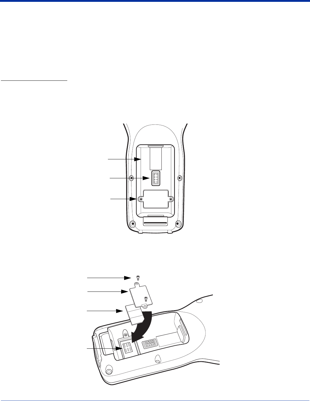
On the Dolphin 9500 terminal, the SIM card door is located in the battery well on the back panel. This enables easy access to
the SIM card while securing it under an installed battery.
To Install a SIM Card:
Note: You need a metric .050 Hex head wrench to open the SIM card door. The SIM card must be activated by the service
provider prior to installation.
1. Turn off your terminal and lay it face-down on a flat surface.
2. Remove the battery pack. For details, see To Remove the Main Battery Pack on page 2-7.
3. Using the Hex head wrench, unscrew the faceplate of the SIM card door.
4. Insert your SIM card. Make sure the interface on the card is connected to the SIM Card interface in the slot; the beveled
corner is in the upper right corner.
5. Place the SIM card door over the secured SIM card and secure the allen screws.
6. Install the battery pack and turn on the terminal.
Battery Well
SIM Card Door
Battery Interface
SIM Card Interface
Allen Screws
SIM Card Door
SIM Card
Dolphin® 9500 Series Mobile Computer User’s Guide - Preliminary Rev (d) 12/17/04 9 - 3
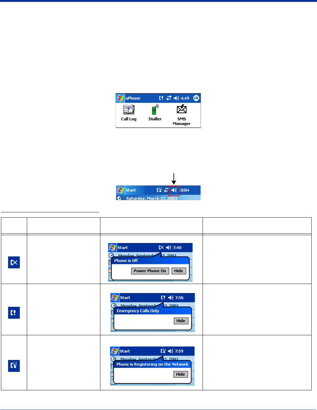
Using uPhone
The uPhone Application Suite contains three programs that function together to provide a complete voice, data, and text
messaging solution for a mobile device fitted with a radio modem:
• Dialler emulates a mobile phone and is used to make and receive telephone calls - Using the Dialler, page 9-6.
• Call Log enables you to view and manipulate a list of the most recent calls - Call Log, page 9-13.
• SMS Manager provides a text message handler similar to many email programs - SMS Manager, page 9-15.
Accessing uPhone
Go to Start > Programs > uPhone. Tap one of the icons to launch the program.
Navigation Bar
When the Dialler or SMS Manager applications are not open, the icons in the Navigation bar at the top of the screen indicates
the status of the phone and messaging system. Each icon indicates s specific action and, when tapped, displays a bubble window
that lets you know what is happening.
Status Icons and Bubble Options
Icon This icon means… Tapping this icon displays this
bubble: Bubble Options
The phone is off.
Tap Power Phone On to turn the phone
on and close the bubble.
Tap Hide to leave the phone off and
close the bubble.
The phone can only make
emergency calls. This
usually means there is no
SIM card installed or PIN
number established.
Tap Hide to dismiss the bubble.
This icon will appear in the Navigation bar
until a SIM card is installed or a PIN is
entered.
The phone is registering
on the network.
Tap Hide to dismiss the bubble.
This is a temporary state. This icon
appears only until the phone is registered
on the network.
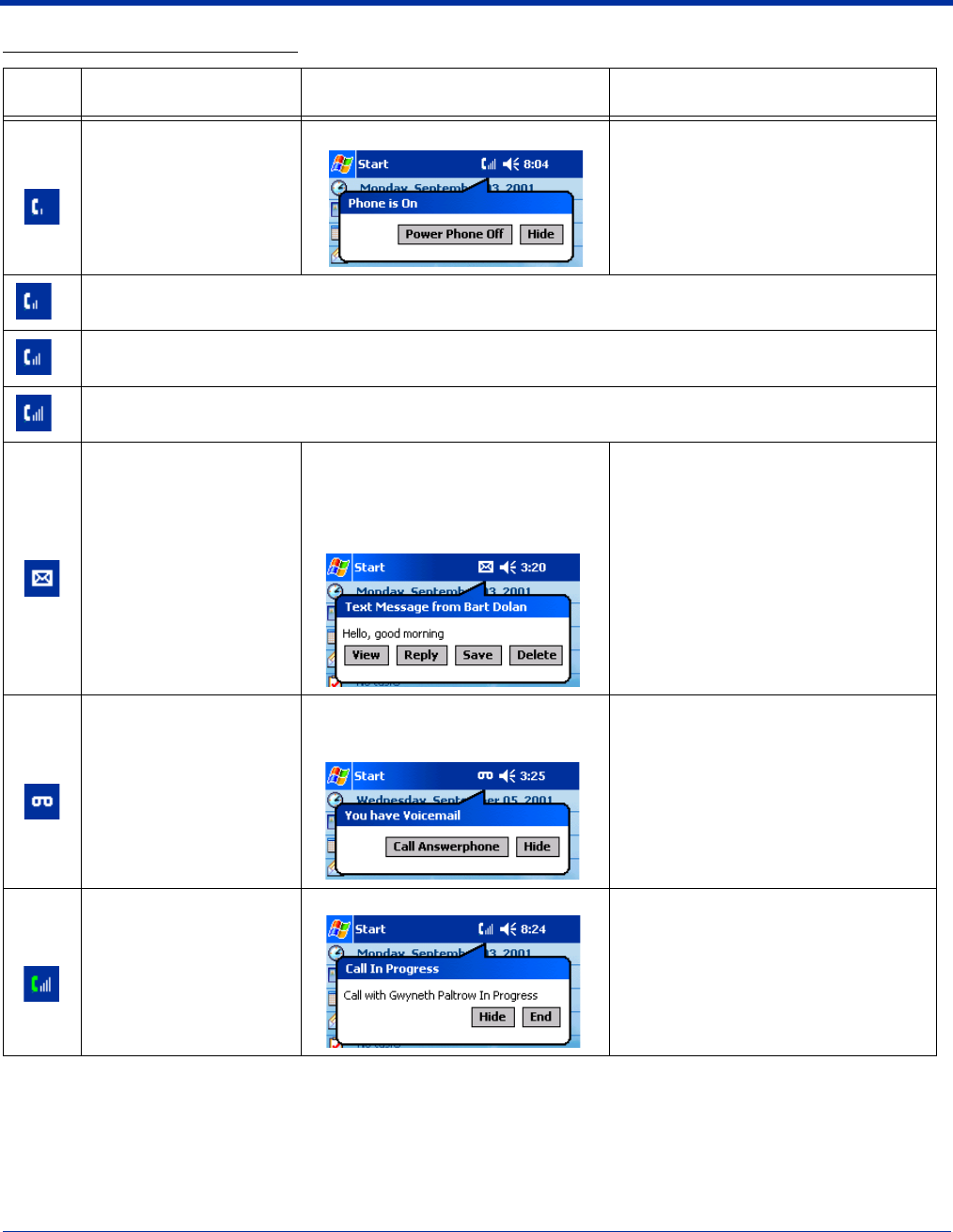
9 - 4 Dolphin® 9500 Series Mobile Computer User’s Guide - Preliminary Rev (d) 12/17/04
The phone is on and
registered.
To the right of the phone is
a bar that indicates signal
strength.
Tap Hide to dismiss the bubble.
Tap Power Phone Off to turn off the
phone. The icon in the Navigation bar
changes to indicate the phone is now off.
Indicates medium signal strength.
Indicates good signal strength.
Indicates full signal strength.
Incoming SMS message
available.
This bubble appears automatically
when a new SMS message is
received. It contains the sender’s
information and the first line of the text
message.
Tap View to display the full message in
SMS Manager.
Tap Reply to switch to the SMS Manager
Compose screen. The 'To:' field is auto-
filled with the sender’s address.
Tap Save to put the message in the SMS
Manager Inbox.
Tap Delete to delete the message.
Tapping each button closes the bubble.
A new voicemail message
is available.
This bubble appears automatically
when a voicemail notification is
received. Tap Call Answerphone to dial the
Answerphone service and retrieve
voicemail messages. To set up
Answerphone, see, uPhone
Configuration, General Tab, page 9-19.
Tap Hide to close the bubble.
There is a call in progress
to the name or number
shown in the bubble.
(This icon is showing full
signal strength; the icon
will change according to
the current signal
strength.)
Tap Hide to close the bubble.
Tap End to end the call.
Status Icons and Bubble Options
Icon This icon means… Tapping this icon displays this
bubble: Bubble Options
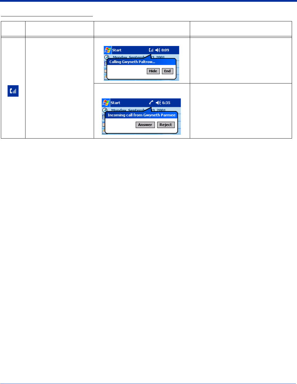
Dolphin® 9500 Series Mobile Computer User’s Guide - Preliminary Rev (d) 12/17/04 9 - 5
This icon appears when
there is a call coming in or
going out.
A different bubble displays
for each circumstance.
If the incoming call is a
conference call, a different
bubble displays.
For a call going out
Tap Hide to close the bubble.
Tap End to end the call.
When a call is coming in, this bubble
displays while the ringtone sounds. If the caller is in the Phonebook, the
name displays. If not in the Phonebook,
the caller’s number displays; if the
number can’t be read, “no number”
displays.
Tap Answer to answer the call; this
places any current call on hold.
Tap Reject to reject the call.
Status Icons and Bubble Options
Icon This icon means… Tapping this icon displays this
bubble: Bubble Options
9 - 6 Dolphin® 9500 Series Mobile Computer User’s Guide - Preliminary Rev (d) 12/17/04
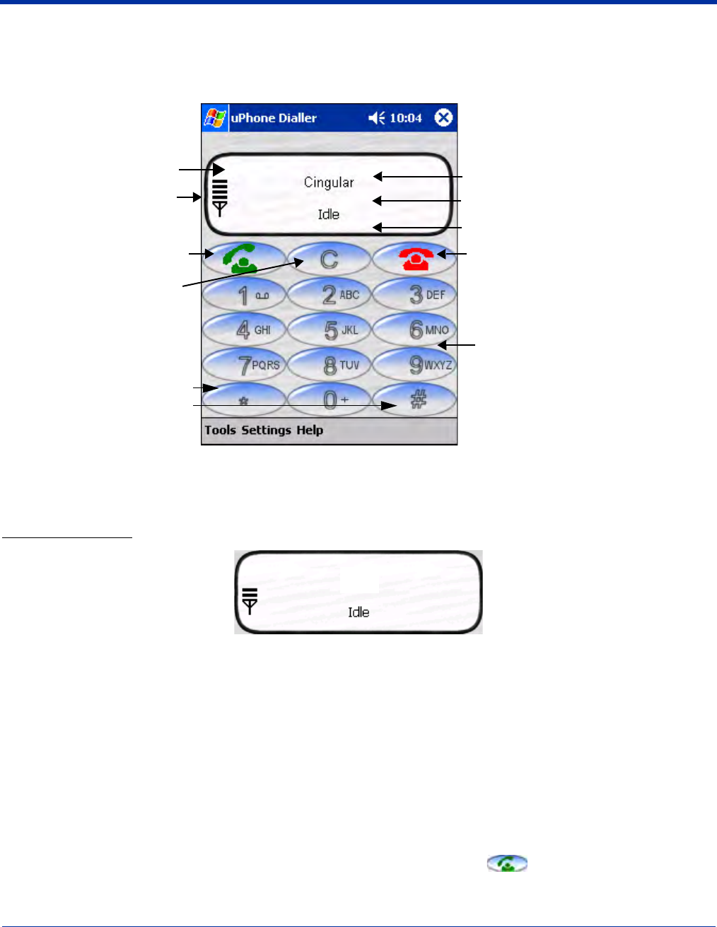
Using the Dialler
The Dialler is the is the program that manages your GSM/GPRS cell phone calls.
To launch the Dialler, tap Start > Programs > uPhone > Dialler. The program launches and the uPhone Dialler screen opens:
Making a Call
To Enter a Number
You can:
• Enter the numbers manually using the phone keypad on the Dialler screen, the SIP, or the Dolphin keyboard.
As you enter each number, the digits appears on the Dialler screen in the Name/Number line. If a contact matching the
entered number is found in the Phonebook, the name of the contact appears in the Name/Number line as you type;
tapping on the name enters the rest of the number automatically.
• Use the Phonebook - Phonebook, page 9-10 - to
• Select an existing contact.
Tap Tools > Phonebook, select a name or number in the list, and tap OK (you can also tap and hold on the entry).
The number is automatically entered in the Dialler and appears on the screen.
• Use speed dial.
Tap and hold on the list to see a popup menu of speed dial numbers.
• Use the Call Log - Call Log, page 9-13.
When the phone is in Idle status, you can tap the Send button on the screen , press the ENTER key, or tap
Tools > Call Log to see a list of the last 20 calls made or received. Tap and hold on an entry in the list and select Dial.
Pressing the Send button or ENTER key performs this function only when the phone is in an Idle Status.
Three information lines:
Network Operator - name of service
provider.
Number/Name - number/ name of dialed,
incoming, and outgoing calls.
Status - displays the status of the phone.
Tap to end a call
Phone keypad - tap the numbers to dial
Signal Strength -
Four bars is optimal.
Tap to send (make) a call or
accept an incoming call
Dialler screen
Tap to clear the Dialler
Tap * and # buttons for
interactive voice systems; also
known as touchtones.
Cingular
Dolphin® 9500 Series Mobile Computer User’s Guide - Preliminary Rev (d) 12/17/04 9 - 7
To Send a Call To a Dialed Number
You can:
• Tap the Send button .
• Press the ENTER key on the keyboard.
• Press the appropriate key combination on the keyboard - Keyboard Combinations for Calls, page 9-8.
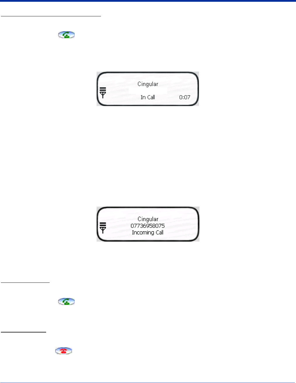
When the call is connected, the three information lines display the following:
Network Operator Displays the name of the service provider you are using.
Name/Number Displays the name and/or number you called. If the number is from your Phonebook, that entry
displays.
Status The status of the call.
Idle - means no calls are incoming or outgoing.
In Call - means a phone call is in progress.
Incoming Call - means that a a call is coming in.
0:00 The numbers in the lower, right corner display the minutes:seconds that have elapsed.
Receiving a Call
When the Dialler screen is open and an incoming call is detected, text is displayed on the Dialler screen. If the Dialler is not visible
at the time of the incoming call, a Navigation Bar notification appears; see Status Icons and Bubble Options on page 9-3.
When a call is coming in, the ringtone sounds and the three information lines on the Dialler screen display the following:
Network Operator Displays the name of the service provider you are using.
Name/Number Displays the name and/or number calling in. If the number is in your Phonebook, that entry displays.
Status Incoming Call.
To Answer a Call
To answer a call, you can:
• Tap the Send button .
• Press the ENTER key on the keyboard.
• Press the appropriate key combination on the keyboard - Keyboard Combinations for Calls, page 9-8.
To Reject a Call
You can:
• Tap the End button .
• Press the appropriate key combination on the keyboard - Keyboard Combinations for Calls, page 9-8.
Joe Smith
9 - 8 Dolphin® 9500 Series Mobile Computer User’s Guide - Preliminary Rev (d) 12/17/04
Call Waiting
If call waiting is enabled, a second incoming call can be received while a first call is in progress. The second incoming call uses
a different ringtone but displays the same incoming call notification.
If a second call is coming in, answering it (see To Answer a Call on page 9-7) automatically places the first call on hold. You can
also reject the second call; see To Reject a Call on page 9-7.
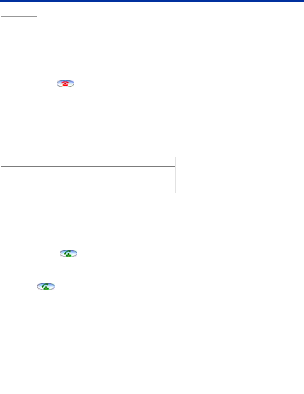
Ending a Call
To end or reject a call, you can:
• Tap the End button .
• Press the appropriate key combination on the keyboard.
Call Waiting If two calls are in progress, the above options end the active call and place the other on hold.
To activate the call on hold, tap Send or press ENTER or the key combination to send calls.
To end the call on hold, tap End or press the key combination to end calls on the keyboard.
Conference Call If a conference call is in progress, tap End or the key combination to end calls.
Call Waiting
The uPhone Dialler supports call waiting functionality. This means that you can receive a second call while on a first call.
Placing a Current Call on Hold
When a second call is coming in, to place the current call on hold
• Tap the Send button .
• Press the ENTER key on the keyboard.
• Press the key combination for sending calls on the keyboard.
The Status line of the first call changes to Call on Hold.
Tapping Send again restores the call on hold.
Making a Second Call To make a second call, place the current call on hold, then dial the second number. When there are
two calls (one active and one held) the status line displays In Call, Call on Hold.
Switching Between Calls To switch between the active and held call, tap Send, press ENTER, or the appropriate key
combination to send calls. The display is updated to show the active call details, and that the other
call is on hold.
Keyboard Combinations for Calls
Each keyboard option contains a key combination to send and end a call using the Red modifier key.
Keyboard To Send, Press… To End (reject), Press…
35-key keyboard Red + SP Red + DEL
43-key keyboard Red + D Red + H
56-key keyboard Red + 3 Red + 6
Dolphin® 9500 Series Mobile Computer User’s Guide - Preliminary Rev (d) 12/17/04 9 - 9
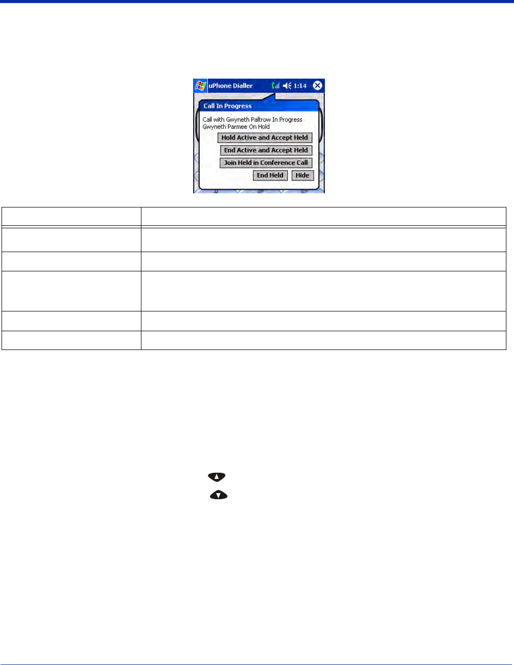
Making Conference Calls
In addition to supporting call waiting functionality, the uPhone Dialler enables you to join two calls into a conference call.
When two calls are in progress, tap the phone icon on the Navigation bar. This opens a bubble dialog that enables you to
conference both calls into one.
Touchtones
To transmit touchtones for interactive voice systems while in a call, you can
• Tap the 0-9, *, and # buttons on the uPhone Dialler screen.
• Press 0-9 keys on the Dolphin keyboard; use the uPhone Dialler screen buttons for * and #.
Volume Control
Use the Dolphin keyboard to manually adjust the volume.
To raise the volume, press the Blue modifier key + (VOL+)
To lower the volume, press the Blue modifier key + (VOL-)
Button Tapping this button…
Hold Active and Accept Held Swaps between the currently held and active calls. Tapping Send or pressing ENTER
performs the same function without opening this bubble dialog.
End Active and Accept Held Drops the current active call and connects the held call.
Join Held in Conference Call
Connects the held call and the currently active call in a three-way conference call.
More than three parties can join a conference call via networking; each of the other
parties can add another call to the conference, and so on.
End Held Drops the held call, and continues with the currently active call.
Hide Closes the bubble.
9 - 10 Dolphin® 9500 Series Mobile Computer User’s Guide - Preliminary Rev (d) 12/17/04
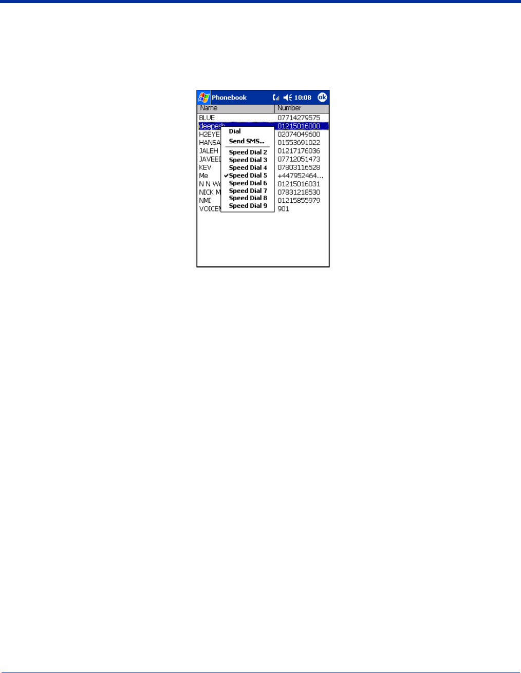
Phonebook
The Phonebook contains the contacts from the SIM card and Pocket Contacts. If fixed dialing is set in the SIM, then only those
numbers in the fixed dialing list are shown in the Phonebook, and only these numbers can be called from the Dialler.
You can access the Phonebook manually by opening the Dialler and going to Tools > Phonebook. When you tap and hold on
an entry, a popup menu displays.
Dial Opens the Dialler with the number entered ready for dialing.
Send SMS Opens the SMS Manager in the Compose screen with the 'To:' field populated with the number.
Speed Dial 2-9 These eight slots are used to assign the Dialler Speed Dial keys. To assign a number to a Speed Dial
slot, tap on an entry to assign the number. Tapping and holding the associated button when in Dialler
will automatically dial the assigned contact.
Dolphin® 9500 Series Mobile Computer User’s Guide - Preliminary Rev (d) 12/17/04 9 - 11
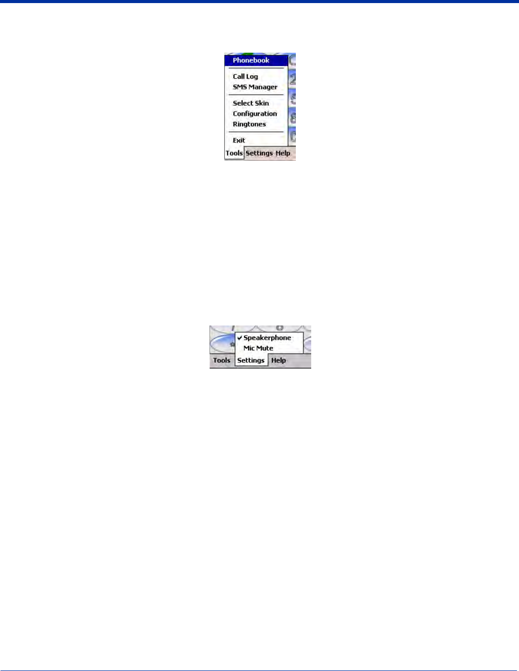
Tools Menu
The Tools menu provides the following options:
Select this item To…
Phonebook Display the Phonebook.
Call Log Switch to the Call Log.
SMS Manager Switch to the SMS Manager Inbox.
Select Skin Allow selection of a new skin for the uPhone Dialler application.
Configuration Open the uPhone Configuration control panel
Ringtones Switch to the ring tone selection control panel.
Exit Exit the uPhone Dialler.
Settings Menu
The Settings menu provides the following options:
Speakerphone Toggles speakerphone mode on and off. When an audio plug (for a headset) is inserted into the audio
jack (2.5mm), Speakerphone is inactive on this menu.
Mic mute Toggles microphone mute on and off (the other party cannot hear a private conversation when the
microphone is muted). This mode is active only during a call and automatically cancelled at the end
of a call.
A checkmark to the left of the entry indicates that the mode is active. When the entry is grayed-out, it is unavailable and cannot
be selected.

9 - 12 Dolphin® 9500 Series Mobile Computer User’s Guide - Preliminary Rev (d) 12/17/04
Audio Modes
The back panel of the Dolphin 9500 contains both a speaker and a microphone that you can use to send and receive audio
signals over the GSM network. For details about the microphone and speaker on the back panel of the Dolphin 9500, see Back
Panel Features on page 3-4.
There are three audio modes: Handset, Headset, and Hands-free (speakerphone).
Handset
Handset mode is when you use the use the back panel of the terminal just as you would a cell phone, holding the speaker to your
ear to receive audio information and the your mouth over the microphone to send audio information.
This is the default audio mode.
Headset
Headset mode is when you plug a headset into the audio jack and speak into the microphone. You must use a 2.5mm plug; no
other audio plug will fit.
Hands-Free
Hands-free mode is when you use the back panel of the Dolphin 9500 as a speakerphone.
To switch the back panel to speakerphone, in the Dialler, tap Settings > Speakerphone. The audio levels adjust appropriately
for speakerphone use. For more information, see Settings Menu on page 9-11.
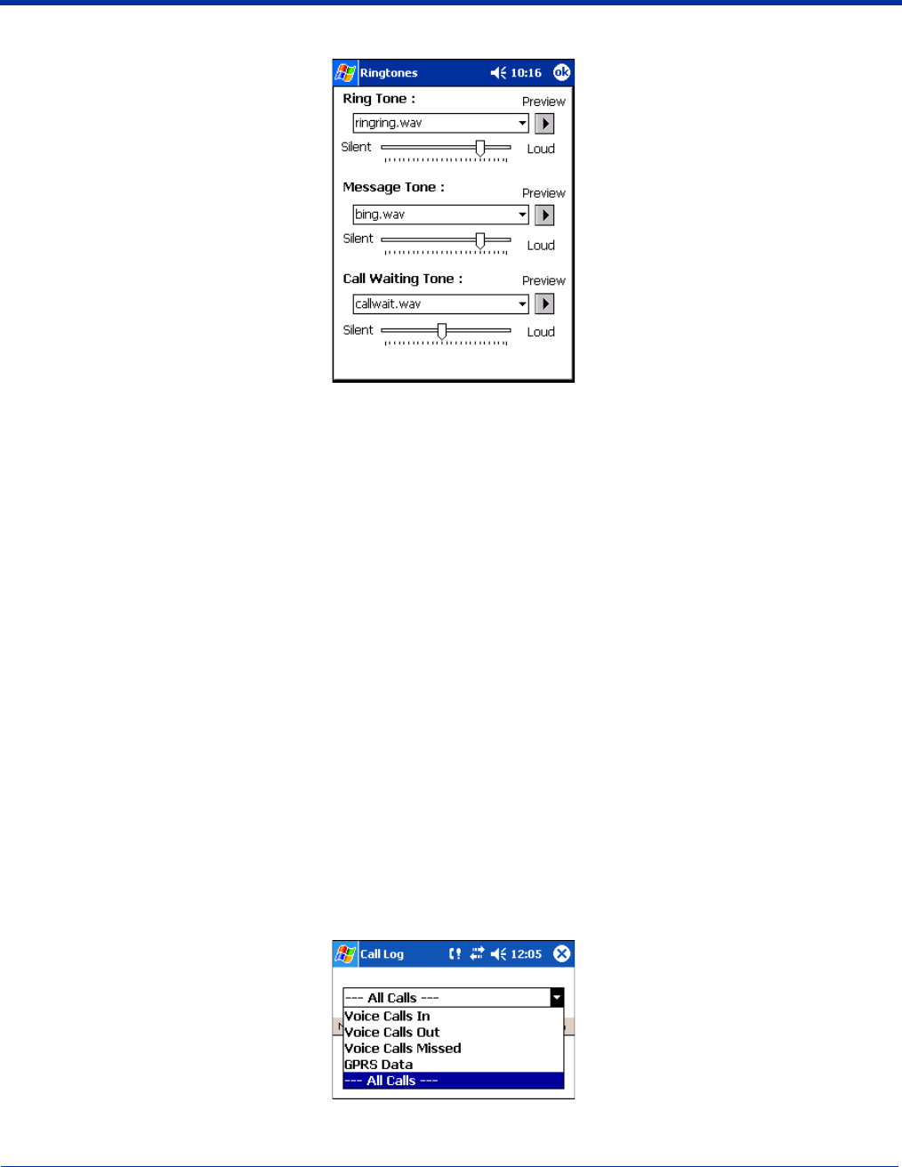
Ringtone Configuration
Different ringtones, with individual volume settings, can be set for the following:
Ring Tone Sounds on an incoming call.
Message Tone Sounds on an incoming SMS or Voicemail notification.
Call Waiting Tone Sounds to indicate an incoming call while you are already on a voice call.
Accessing Ringtone Configuration
You can access Ringtones two ways:
1. Go to Start > Settings > Personal tab > Ringtones icon OR
2. Open the Dialler (tap Start > Programs > uPhone > Dialler) and go to Tools > Ringtones.
Dolphin® 9500 Series Mobile Computer User’s Guide - Preliminary Rev (d) 12/17/04 9 - 13
The Ringtones screen opens displaying the current settings.
Select the desired ringtone for each type of tone in the drop-down lists. Tapping OK saves any changes. Opening another screen
without tapping OK discards any changes.
WAV Files
You can customize your ringtones with *.wav files installed on your terminal. To appear here, *.wav files must be stored in the
Programs Files > uPhone >Ring Tones folder.
Previewing Tones
You can preview each tone by selecting the *.wav file in the drop-down list and tapping the Preview button. Use the slider to set
the volume for each tone.
While the tone is playing, the Preview button changes to a Stop button; tap it to stop the preview.
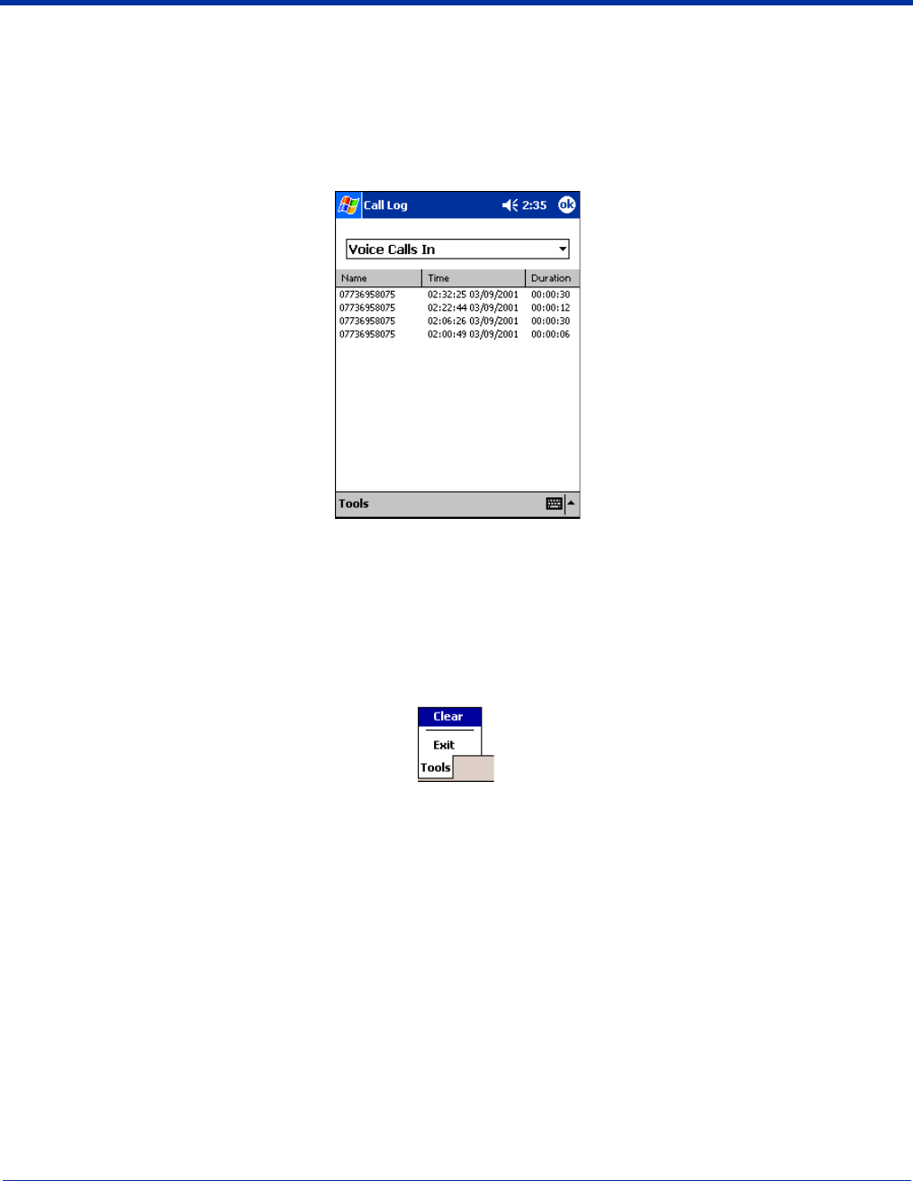
Call Log
The Call Log maintains a list of the last 20 calls made or received in each of the following categories:
• Voice Calls In
• Voice Calls Out
• Voice Calls Missed
• GPRS Data
Voice Call In is the default display whenever the Call Log is opened.
Call Log Options
Voice Calls Out and Voice Calls Missed are available from the drop-down list. Select the option you want to view.
To see everything, select All Calls.
9 - 14 Dolphin® 9500 Series Mobile Computer User’s Guide - Preliminary Rev (d) 12/17/04
Opening the Call Log
You can access the Call Log two ways:
1. Go to Start > Programs > uPhone > Call Log) OR
2. Open the Dialler (go to Tools > Call Log).
The Call Log opens displaying the last few Voice Calls In; the most recent call always appears at the top.
This column Displays the …
Name The phone number or the name if the call was from or to a matching entry in the Phonebook.
Time Time and date the call started. This is the local time and date.
Duration Duration of the call (hours:minutes:seconds). The clock starts when the call connects, not when
dialed.
Tools Menu
The Tools menu in the Call Log provides the following options:
Select this menu option To…
Clear Delete the entire Call Log.
Exit Close the Call Log.
Dolphin® 9500 Series Mobile Computer User’s Guide - Preliminary Rev (d) 12/17/04 9 - 15
SMS Manager
Abbreviated for Short Message Service, SMS enables the transmission of short messages (140-160 characters) to and from a
cell phone. SMS messages travel over the system's control channel, which is separate from the voice channel.
The SMS Manager on the Dolphin 9500 supports creation, sending, receiving, and storing of SMS text messages. Text
messages sent or received can be up to 160 characters long.
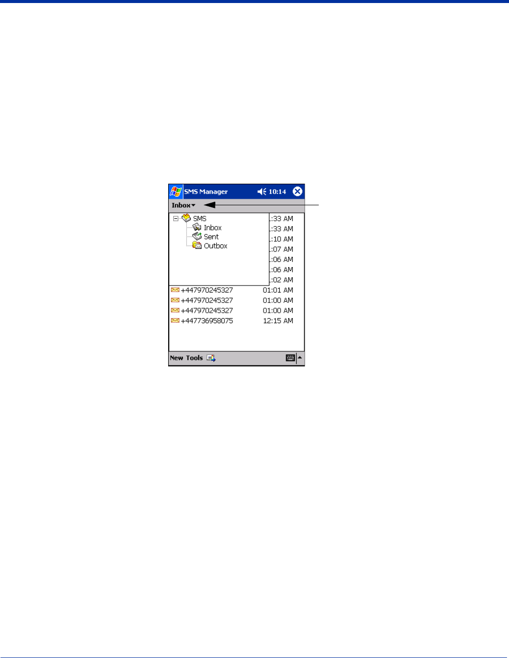
Opening the SMS Manager
You can access the SMS Manager two ways:
1. Go to Start > Programs > uPhone > SMS Manager, OR
2. Open the Dialler (Start > Programs > uPhone > Dialler) and go to Tools > SMS Manager. The SMS Manager opens
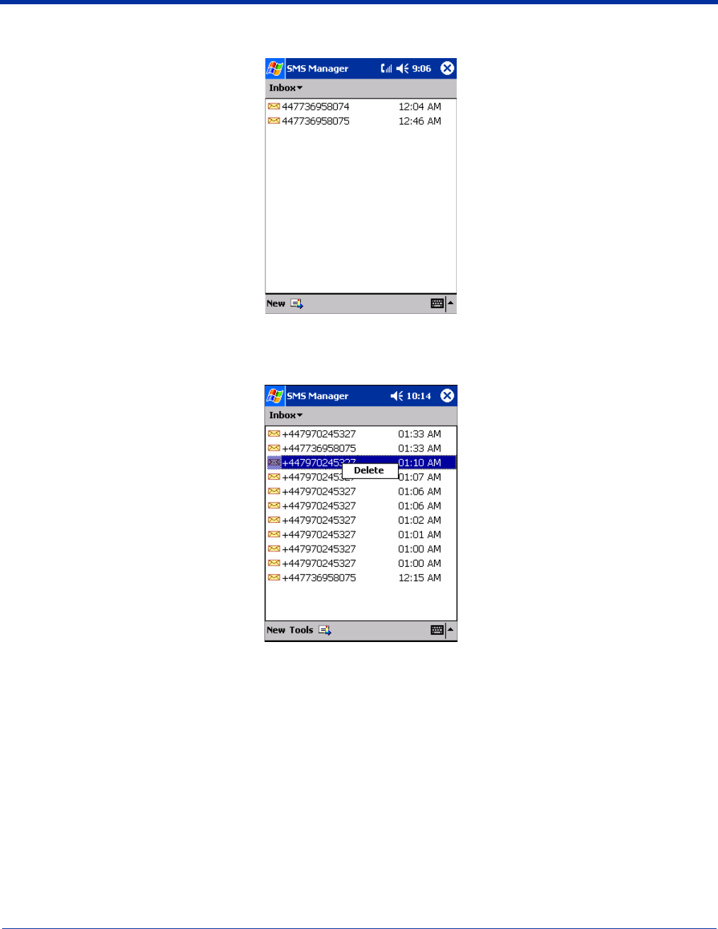
displaying a list of your most recent text messages. Tap the Inbox and the SMS folders drop-down.
Three folders are available from the Inbox menu:
Select this folder To see…
Inbox Received text messages.
Sent Sent text messages.
Outbox Text messages waiting to be sent (messages are moved to the Sent folder automatically after
transmission).
Tap here
9 - 16 Dolphin® 9500 Series Mobile Computer User’s Guide - Preliminary Rev (d) 12/17/04
When the folder is selected, the messages in it appear in the list. The name of the folder appears in the gray bar just under the
title bar.
To Do this…
Open a message Tap on it in the list.
Delete a message Tap and hold on it in the list. A popup menu appears that enables you to delete the message.
Dolphin® 9500 Series Mobile Computer User’s Guide - Preliminary Rev (d) 12/17/04 9 - 17
Sending an SMS Message
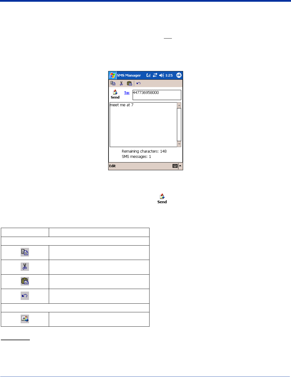
1. In the task tray at the bottom of the screen, tap New. The new message screen opens with the cursor active in the text area.
2. Tap inside the To: field. To add the number, you can type it in or tap To: to select an entry from your Phonebook.
• You must type a number that is in the appropriate international ISDN format for the country you are dialing. However,
you can dial a local number without the country code.
• Destination numbers can start with a “+” sign.
3. Tap inside the text area. To write a message, you can use the SIP or the keyboard.
The Remaining characters field displays how many characters you can type. It counts backwards from 160 as you type each
character.
4. When finished typing, tap the Send icon to transmit the message .
If you tap OK before tapping send, the program requests confirmation before discarding the message.
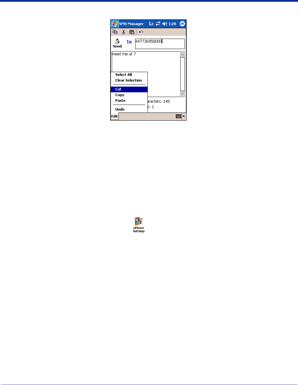
Edit Menu
The Edit menu in the command bar provides the same options as the icons at the top of the screen, with the following additional
options:
Select All Selects all text in the active message section.
Icons at the Top of the Screen
Tap this icon To…
At the top of the window:
Copy selected text.
Cut selected text.
Paste text.
Undo the previous action.
In the task tray at the bottom of the window:
Send all messages in the Outbox.
9 - 18 Dolphin® 9500 Series Mobile Computer User’s Guide - Preliminary Rev (d) 12/17/04
Clear Selection De-selects all text in the active message section.
Online Help
Tapping Help > About provides information about the uPhone applications.
uPhone Configuration
uPhone Settings enable you to establish the normal operating parameters for uPhone applications.
Accessing
You can access uPhone Settings two ways:
1. Go to Start > Settings > System tab > uPhone icon .
2. In the Dialler application, selecting Tools > Configuration.
Requirements
Because this control panel adjusts network settings, the GSM radio must be powered up, and a SIM must be installed for it to
open correctly. If not, you will receive a notification message when you try to open the control panel.
If the radio is powered up and a SIM installed, an animated wait icon displays the following message while the system accesses
the network: “Settings on the Network are being accessed. Please wait…”
If there is no response from the network within 60 seconds, this message times-out and the control panel closes. Otherwise, the
uPhone Settings screen displays; the General tab appears first by default.
Dolphin® 9500 Series Mobile Computer User’s Guide - Preliminary Rev (d) 12/17/04 9 - 19
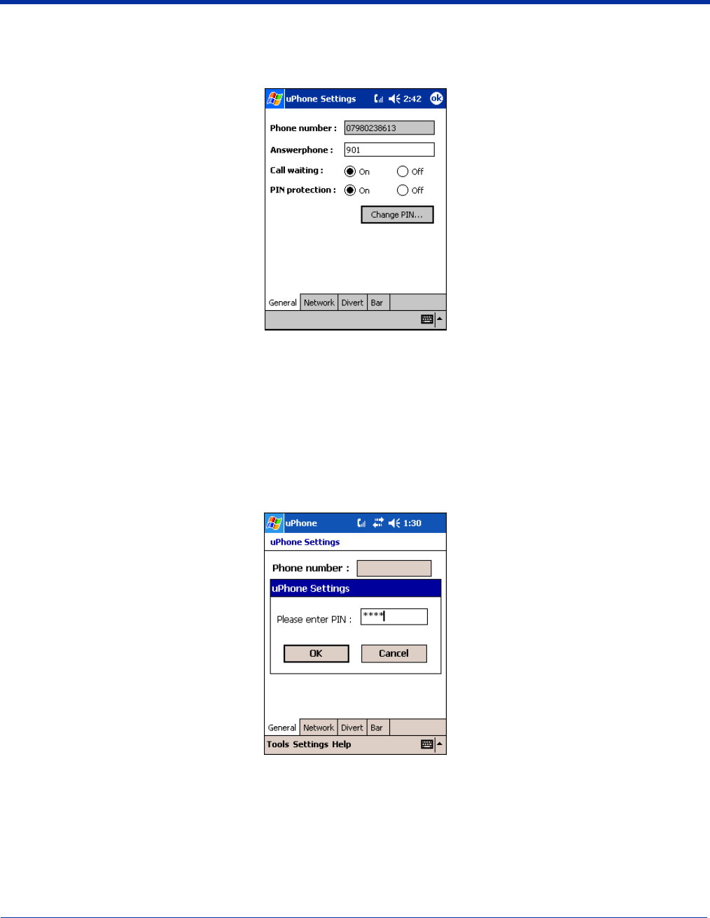
General Tab
uPhone Settings consists of four tabs: General, Network, Divert and Bar. The tabs move up the screen if the SIP is opened for
text or number entry. Tapping OK accepts any changes and exits the control panel.
Field Description
Phone Number This is the phone number stored on the SIM. It is displayed here for information only.
Answerphone This is the number to dial to retrieve voicemail messages. To enter a new number, tap on this field
and enter the digits.
Call waiting Select On or Off to enable or disable call waiting functionality. Call waiting must be set to On for
conference calls.
PIN protection Select On or Off to enable or disable PIN protection. If enabled, a PIN number is requested when the
phone is switched on.
Change PIN This button is active only if PIN protection is set to On. Otherwise, the button is grayed-out.
If you tap Change PIN, a dialog box appears enabling you to change the PIN.
In the Old PIN field, enter the current PIN, then enter the new PIN in the New PIN and Confirm PIN
fields. Tap OK to save the change. If you do not tap OK, the old PIN remains in effect.
While typing, the numbers appear as asterisks to protect the number from observation by third
parties.
9 - 20 Dolphin® 9500 Series Mobile Computer User’s Guide - Preliminary Rev (d) 12/17/04
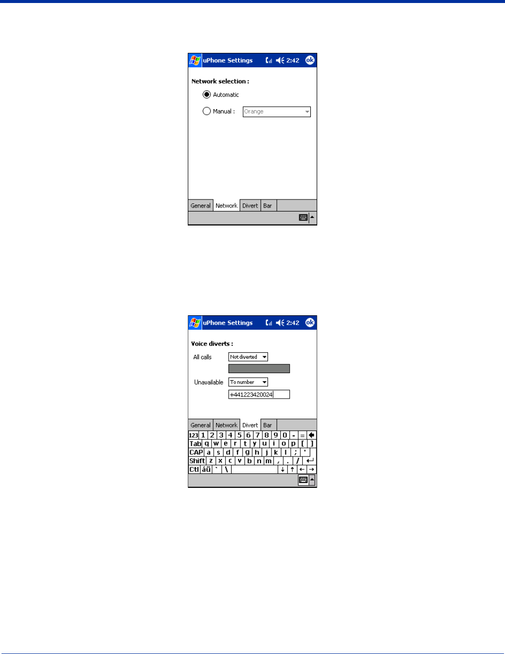
Network Tab
The Network tab provides the ability to choose between Automatic and Manual network selection.
If you choose Manual network selection, the drop-down list of available networks activates. Choose a network from this list and
tap OK. A wait icon appears while the system accesses the selected network.
Divert Tab
The divert tab enables you to select divert options for incoming calls when you are unavailable to answer; e.g., when the phone
is off, you are out of network coverage, busy, or not able to answer.
Select an option from the All Calls drop-down list to divert all incoming calls automatically.
Select an option from the Unavailable drop-down list to divert incoming calls when you are unavailable.
The options in both lists are as follows:
Not Diverted Select this option to not divert calls. This is the default setting.
Answerphone Select this option to divert calls to voicemail.
To number Select this option to forward incoming calls to another number. Enter that number in the field below
the drop-down list.
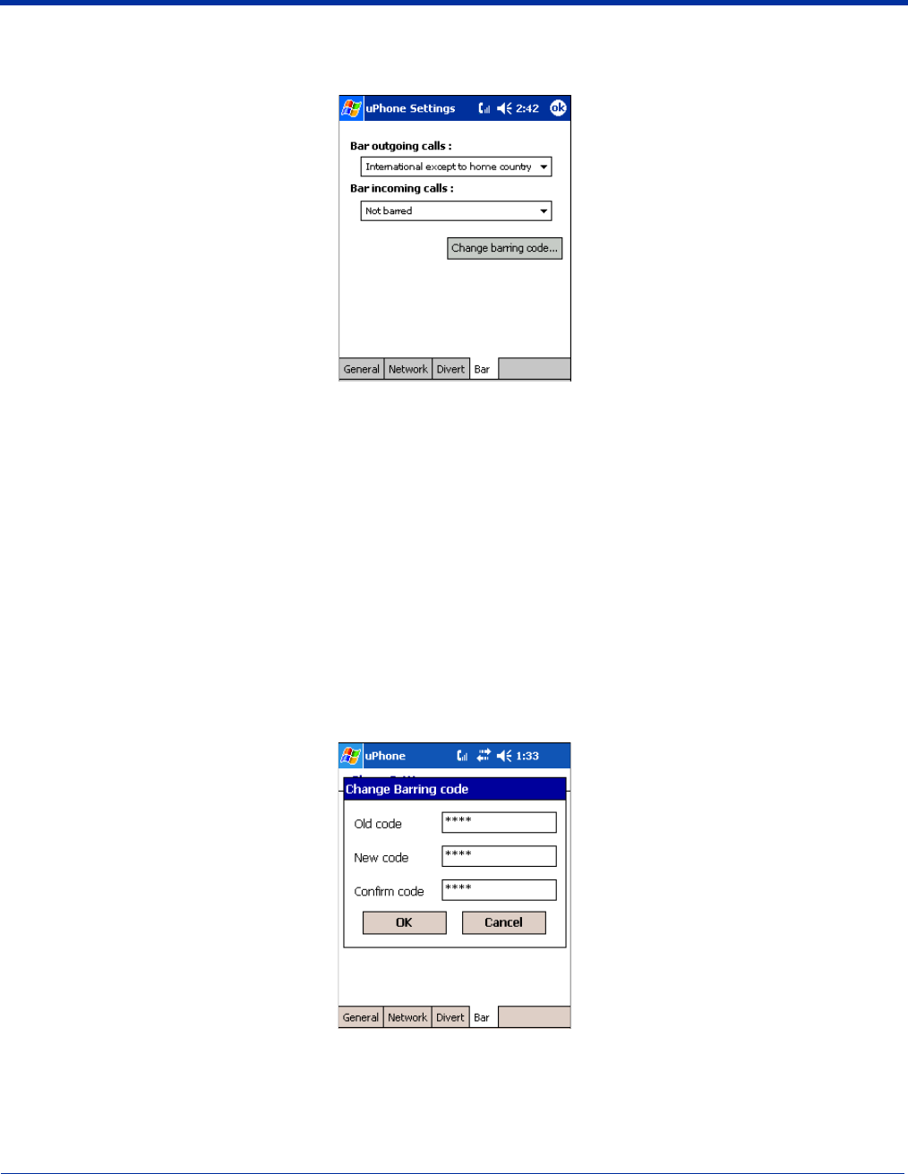
Dolphin® 9500 Series Mobile Computer User’s Guide - Preliminary Rev (d) 12/17/04 9 - 21
Bar Tab
The Bar tab sets enables you to bar both incoming and outgoing calls.
Bar outgoing calls Select one of the following options from the drop-down list:
Bar incoming calls Select one of the following options from the drop-down list:
Change barring code Tap this button to change the barring code. A dialog box appears that enables you to change the
barring code.
In the Old code field, enter the current code, and enter the new code in the New code and the
Confirm code fields. Tap OK to save the change.
While typing, the numbers appear as asterisks to protect the number from observation by third
parties.
To save the barring options, tap OK. The system displays a dialog requesting the barring password before sending the updated
settings to the network. Type in the password and tap OK.
Not barred No restrictions on outgoing calls.
International calls Bar international calls.
International except to
home country
Only international calls to the home country designated on the SIM
card can be made.
All outgoing calls Bar all outgoing calls.
Not barred No restrictions on incoming calls.
Incoming calls when
roaming Bar incoming calls when the network coverage is in roaming status.
All incoming calls Bar all incoming calls.
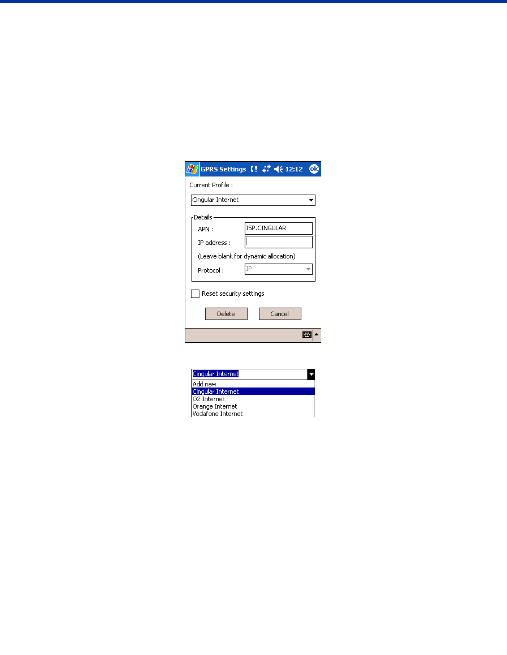
9 - 22 Dolphin® 9500 Series Mobile Computer User’s Guide - Preliminary Rev (d) 12/17/04
GPRS Settings
After subscribing to a GPRS network and installing your SIM card, you can load the parameters of your GPRS subscription into
the terminal. However, some subscriptions load automatically when you install your SIM card. If the GPRS settings do not load
automatically, you must enter them manually.
uPhone includes a pre-configured GPRS connection in Internet Settings. You need to select or create GPRS settings prior to
making a GPRS call for the first time. You can also configure GPRS settings for browsing the web via a VPN or Proxy Server.
To Select Pre-Configured GPRS Settings
1. Go to Start > System > Connections tab > uPhone GPRS. The GPRS Settings screen appears displaying the default
settings.
The Current Profile drop-down list contains a number of pre-configured connection profiles.
2. If the profile associated with your account appears in the list, select it. If it does not appear in the Current Profile list, you need
to create one. For details, see To Add a GPRS Setting on page 9-23.
3. In the Details section
• Type in the APN number
• Type in the IP address
• Select the Protocol
4. Tap OK to save.
Note: Select Reset security settings to reset the username and password, see To Add a GPRS Setting on page 9-23..
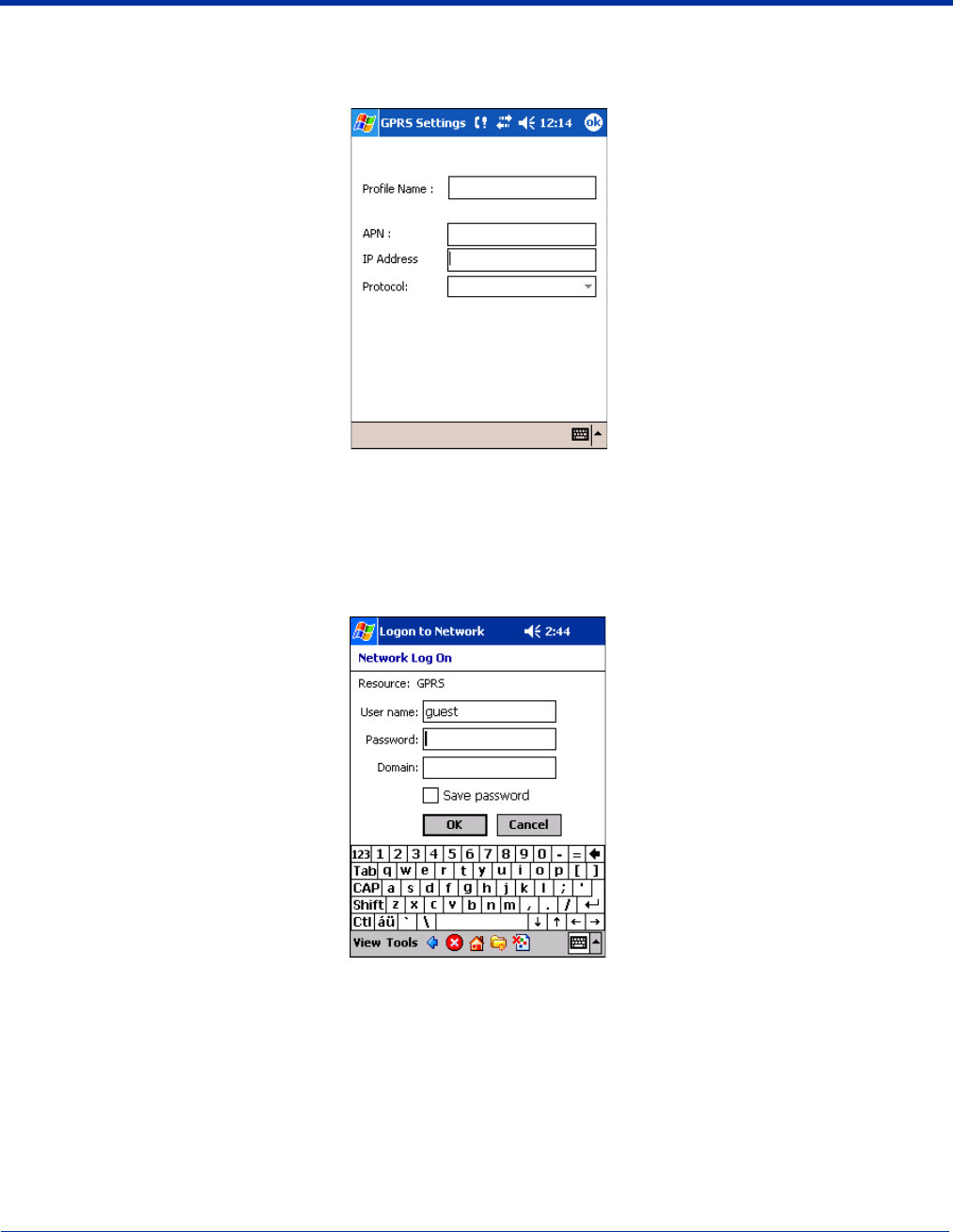
Dolphin® 9500 Series Mobile Computer User’s Guide - Preliminary Rev (d) 12/17/04 9 - 23
To Add a GPRS Setting
1. On the GPRS Settings screen, in the Current Profile drop-down list, select Add new.
2. Type in the Profile Name, APN, IP Address, and select the Protocol.
3. Tap OK. You return to the settings screen. The Profile Name you selected now appears in the Current Profiles list.
GPRS Connection
When a GPRS connection is required - e.g., by navigating to a web site - a Network Log On screen is automatically displayed.
Enter the Password and Domain, then tap OK to connect.

9 - 24 Dolphin® 9500 Series Mobile Computer User’s Guide - Preliminary Rev (d) 12/17/04
You have the option of disconnecting by tapping on the GPRS connection icon in the navigation bar and tapping End.
Establishing GPRS Internet Settings
Because GSM/GPRS technology uses a network connection, you need to configure those settings in the Connection Manager.
For details, see Connections Tab on page 5-15.
Requirements
Make sure that you are not using ActiveSync when configuring the connection settings.
To establish a GPRS connection, you need to review the information from your network service provider. Given that there can
be so many different configurations, such as VPN or Proxy Server connections, see Connections Tab on page 5-15 for instruction
about how to set up each kind of connection.
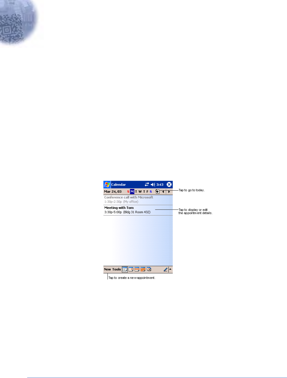
Dolphin® 9500 Series Mobile Computer User’s Guide - Preliminary Rev (d) 12/17/04 10 - 1
10
Applications
Dolphin 9500 Series terminals ship with the following Microsoft applications installed:
• Calendar
• Contacts
• Tasks
• Notes
• Inbox
• Pocket Internet Explorer
• Pocket Word
• Pocket Excel
• Windows Media Player for Pocket PC
• MSN Messenger
• Pictures
Note: Microsoft® Money, Microsoft® Reader are NOT installed on Dolphin terminals when shipped but may be installed from the
Microsoft Companion CD.
Calendar
Use Calendar to schedule appointments, including meetings and other events. You can check your appointments in one of
several views (Agenda, Day, Week, Month, and Year) and easily switch views by using the View menu.
Note: You can customize the Calendar display, such as changing the first day of the week, by tapping Options on the Tools
menu.
To Create an Appointment
1. If you are in Day or Week view, tap the desired date and time for the appointment.
2. Tap New.
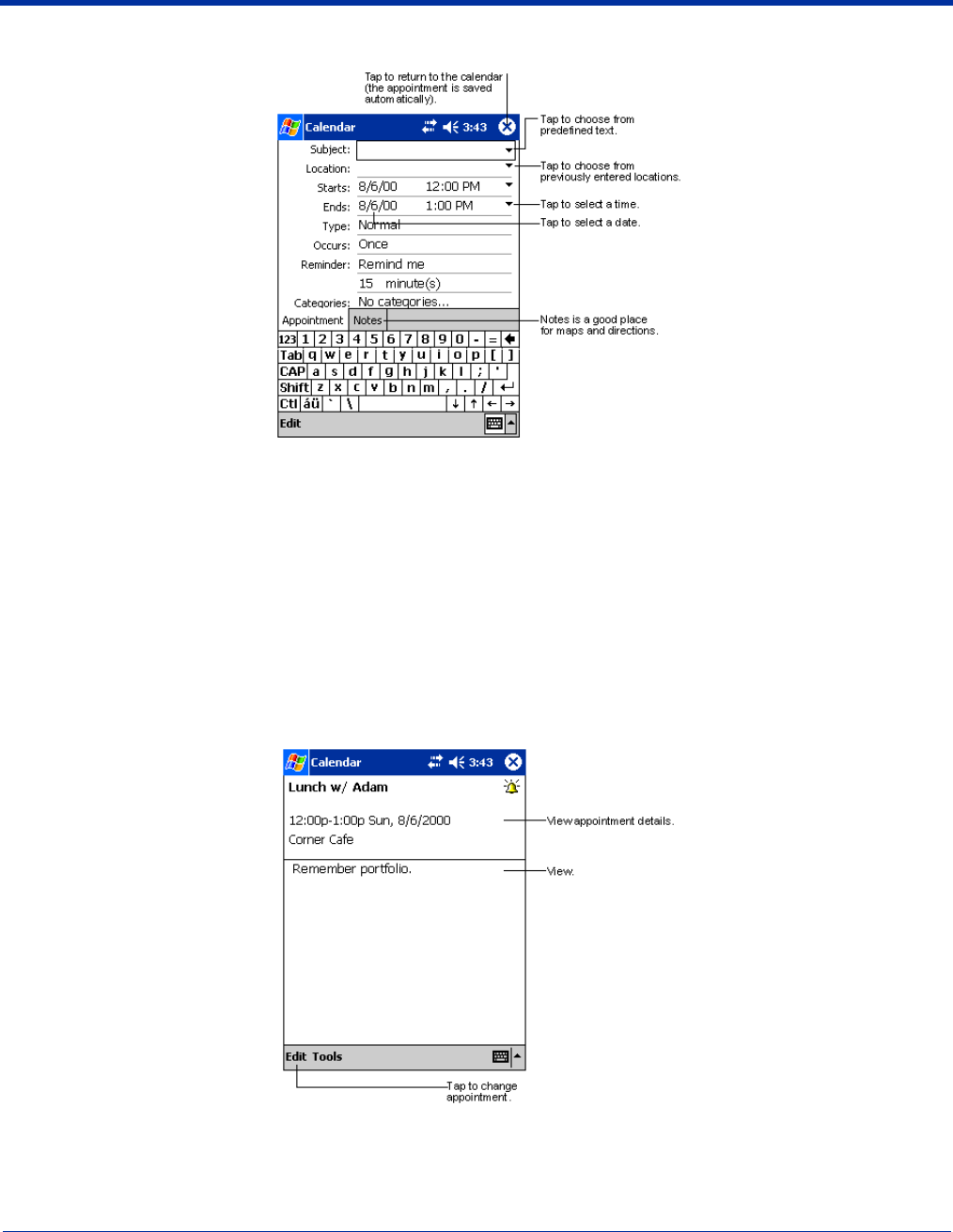
10 - 2 Dolphin® 9500 Series Mobile Computer User’s Guide - Preliminary Rev (d) 12/17/04
3. Using the input panel, enter a description and a location. Tap first to select the field.
4. If needed, tap the date and time to change them.
5. Enter other desired information. To see all available fields, hide the input panel.
6. To add notes, tap the Notes tab. You can enter text, draw, or create a recording. For more information on creating notes,
refer to Notes on page 10-7.
7. When finished, tap OK to return to the calendar.
Note: If you select Remind me in an appointment, you will be reminded according to the options set in Start > Settings >
Personal tab > Sounds & Reminders.
Using the Summary Screen
When you tap an appointment in Calendar, a summary screen displays the details of the appointment.
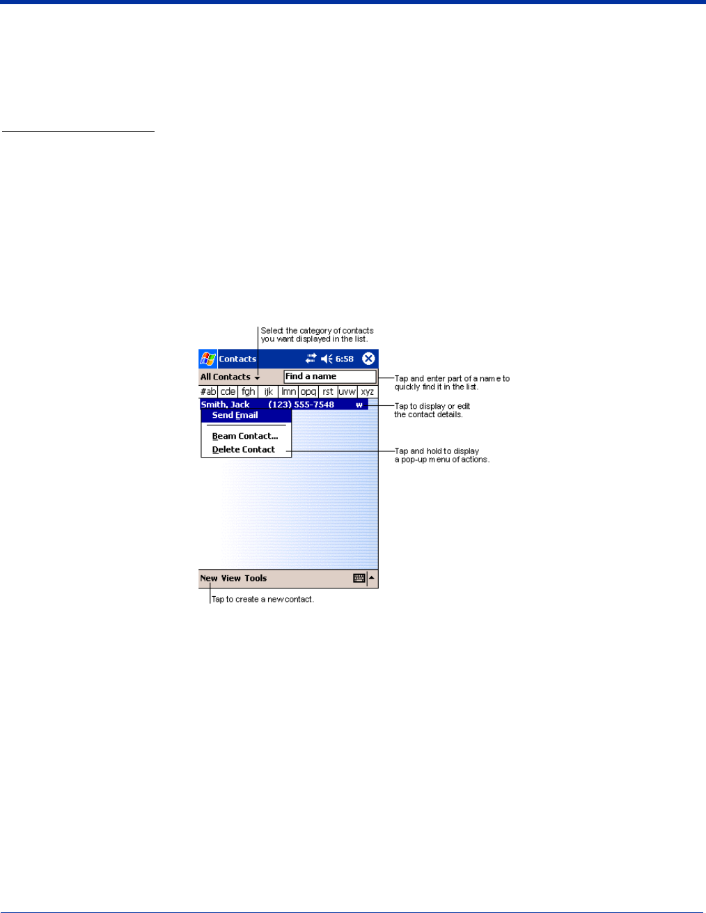
Dolphin® 9500 Series Mobile Computer User’s Guide - Preliminary Rev (d) 12/17/04 10 - 3
Creating Meeting Requests
You can use Calendar to set up meetings with users of Outlook or Pocket Outlook. The meeting request is created automatically
and sent either when you synchronize Inbox or when you connect to your e-mail server. Indicate how you want meeting requests
sent by tapping Tools and then Options. If you send and receive e-mail messages through ActiveSync, select ActiveSync.
To Schedule a Meeting
1. Create an appointment.
2. In the appointment details, hide the input panel, and then tap Attendees.
3. From the list of e-mail addresses you’ve entered in Contacts, select the meeting attendees. The meeting notice is created
automatically and placed in the Outbox folder.
For more information on sending and receiving meeting requests, see Calendar Help and Inbox Help.
Contacts
Contacts maintains the contact information - phone numbers, e-mails, addresses, etc. - you need on your terminal.
Note: To change the way information is displayed in the list, tap Tools > Options.
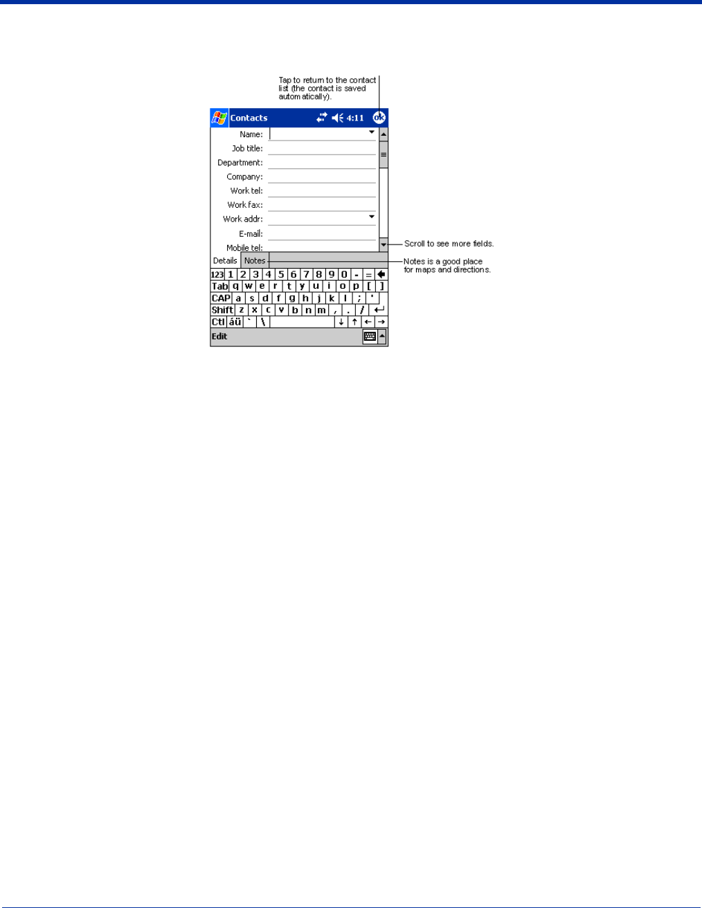
10 - 4 Dolphin® 9500 Series Mobile Computer User’s Guide - Preliminary Rev (d) 12/17/04
To Create a Contact
1. On the Contacts screen, tap New.
2. Using the SIP or Dolphin keyboard, enter the contact’s information. Scroll down to see all available fields.
3. To assign the contact to a category, scroll to and tap Categories, then select a category from the list.
(In the contact list, you can display contacts by category.)
4. To add notes about this contact, tap the Notes tab.
For more information on creating notes, refer to Notes on page 10-7.
5. When finished, tap OK to return to the contact list.
To Search for Contacts
There are four ways to find a contact:
• In the contact list, enter a contact name in the box under the navigation bar. To show all contacts again, clear text from the
box or tap the button to the right of the box.
• In the contact list, tap the category list (labeled All Contacts by default) and select the type of contact that you want displayed.
To show all contacts again, select All Contacts. To view a contact not assigned to a category, select None.
• To view the names of companies your contacts work for, in the contact list, tap View > By Company. The number of contacts
that work for that company are displayed to the right of the company name.
• Tap Start > Find, enter the contact name, select Contacts for the type, and then tap Go.
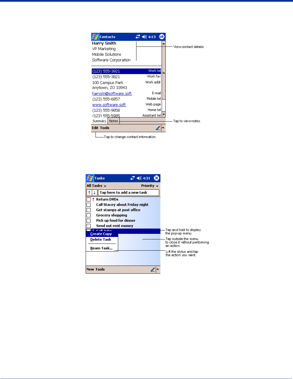
Dolphin® 9500 Series Mobile Computer User’s Guide - Preliminary Rev (d) 12/17/04 10 - 5
Using the Summary Screen
When you tap a contact in the contact list, a summary screen displays their information.
Tasks
Use Tasks to keep track of what you have to do.
Note: To change the way information is displayed in the list, tap Tools > Options.
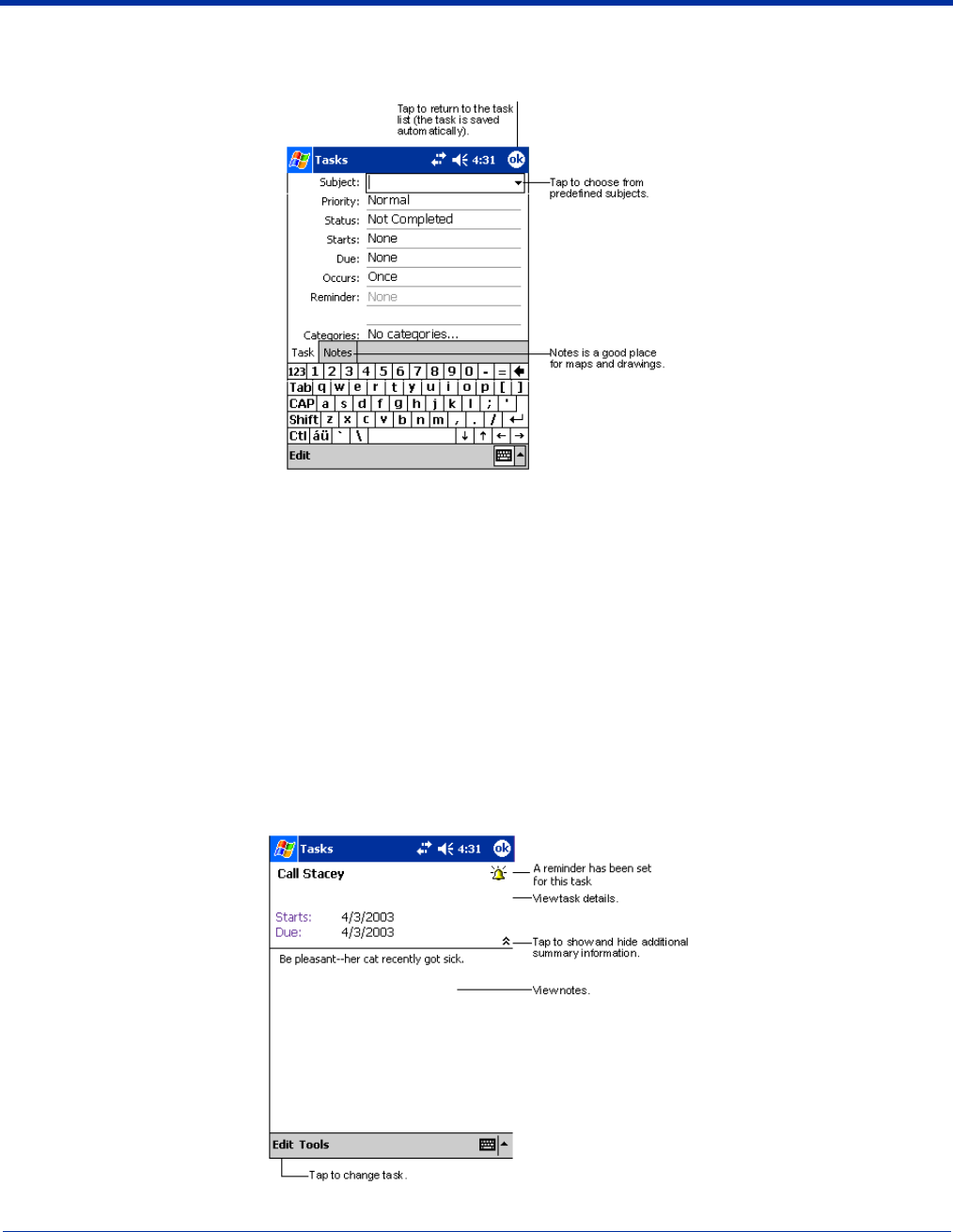
10 - 6 Dolphin® 9500 Series Mobile Computer User’s Guide - Preliminary Rev (d) 12/17/04
To Create a Task
1. Tap New.
2. Using the SIP or Dolphin keyboard, enter the task information.
If the input panel is open, you need to hide it to see all available fields.
3. Tap Starts to enter a start date and/or Due to enter a due date for the task.
4. To assign the task to a category, tap Categories and select a category from the list.
In the task list, you can display tasks by category.
5. To add notes, tap the Notes tab.
For more information on creating notes, refer to Notes on page 10-7.
6. When finished, tap OK to return to the task list.
Note: To quickly create a task with only a subject, tap Entry Bar on the Tools menu. Then, tap Tap here to add a new task and
enter your task information.
Using the Summary Screen
When you tap a task in the task list, a summary screen displays the task information.
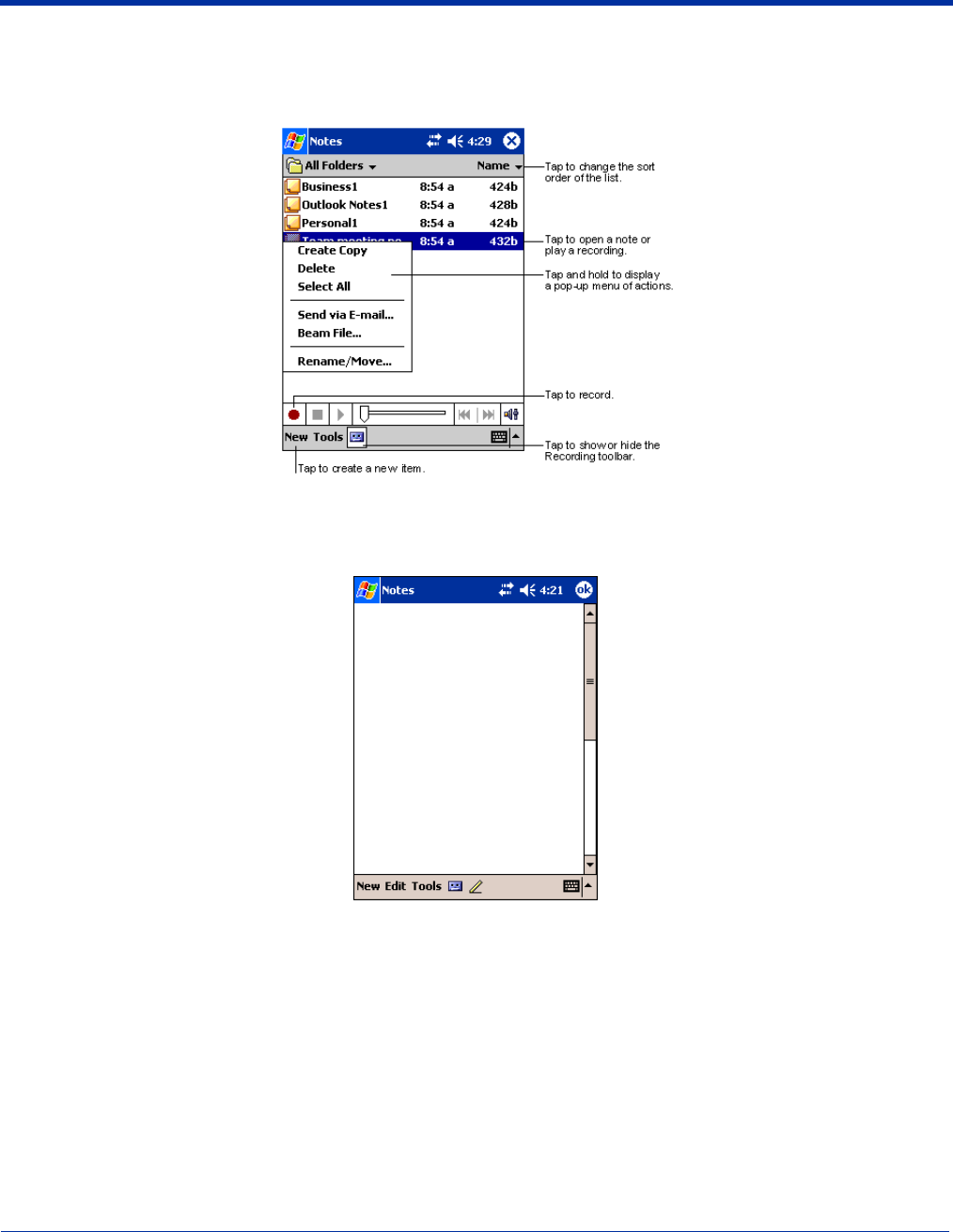
Dolphin® 9500 Series Mobile Computer User’s Guide - Preliminary Rev (d) 12/17/04 10 - 7
Notes
Quickly capture thoughts, reminders, ideas, drawings, and phone numbers with Notes. If a note is open when you create the
recording, it will be included in the note as an icon.
To Create a Note
1. Tap New.
2. Type your note using the SIP or the Dolphin keyboard.
Inbox
Use Inbox to send and receive e-mail messages in either of these ways:
• Synchronize e-mail messages with Microsoft Exchange or Microsoft Outlook on your desktop computer.
• Send and receive e-mail messages by connecting directly to an e-mail server through an ISP or a network.
Synchronizing E-mail Messages
E-mail messages can be synchronized as part of the general synchronization process. You need to enable Inbox synchronization
in ActiveSync. For information on enabling Inbox synchronization, see ActiveSync Help on the desktop computer.
During synchronization:

10 - 8 Dolphin® 9500 Series Mobile Computer User’s Guide - Preliminary Rev (d) 12/17/04
• Messages are copied from the mail folders of Exchange or Outlook on your desktop computer to the ActiveSync folder in Inbox
on the terminal. By default, you will receive messages from the past three days only, the first 100 lines of each message, and
file attachments of less than 100 KB in size.
• E-mail messages in subfolders must be selected in ActiveSync on your desktop computer to be transferred.
• E-mail messages in the Outbox folder on the terminal are transferred to Exchange or Outlook, and then sent from those
programs.
Note: You can also synchronize e-mail messages with your desktop computer from a remote location. For more information,
see Chapter 7.
Connecting Directly to an E-mail Server
In addition to synchronizing e-mail messages with your desktop computer, you can send and receive e-mail messages by
connecting to an e-mail server. When you connect the terminal to the e-mail server, new messages are downloaded to the Inbox
folder, messages in the Outbox folder are sent, and messages that have been deleted on the e-mail server are removed from
the Inbox folder.
Messages received directly from an e-mail server are linked to your e-mail server rather than your desktop computer. When you
delete a message on the terminal, it is also deleted from the e-mail server the next time you connect the terminal to the e-mail
server according to the settings selected in ActiveSync.
You can work online or offline. When working online, you read and respond to messages while connected to the e-mail server.
Messages are sent as soon as you tap Send, which saves space on the terminal. When working offline, after you’ve downloaded
new message headers or partial messages, you can disconnect from the e-mail server and then decide which messages to
download completely. The next time you connect, Inbox downloads the complete messages you’ve marked for retrieval and
sends the messages you’ve composed.
Receiving Messages
When you connect to your e-mail server or synchronize with your desktop computer, by default, you’ll receive messages from
the last five days only, the first 100 lines of each new message, and file attachments of less than 100 KB in size. The original
messages remain on the e-mail server or your desktop computer.
You can mark the messages that you want to retrieve in full during your next synchronization or e-mail server connection. In the
message list, tap and hold the message you want to retrieve. On the pop-up menu, tap Mark for Download. The icons in the
Inbox message list give you visual indications of message status.
You specify your downloading preferences when you set up the service or select your synchronization options. You can change
them at any time:
• Change options for Inbox synchronization using ActiveSync options. For more information, see ActiveSync Help.
• Change options for direct e-mail server connections in Inbox on the terminal. Tap Tools and then tap Options. On the Service
tab, tap the service you want to change. Tap and hold the service and select Delete to remove a service.
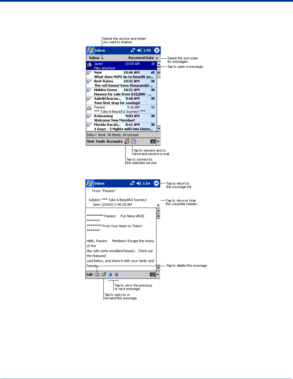
Dolphin® 9500 Series Mobile Computer User’s Guide - Preliminary Rev (d) 12/17/04 10 - 9
Using the Message List
Messages you receive are displayed in the message list. By default, the most recently received messages are displayed first in
the list and unread messages are displayed in bold type.
When you tap on a message to open it, the following screen appears:
Composing Messages
1. Tap New.
2. In the To field, enter the e-mail or SMS address of one or more recipients, separating them with a semicolon (;), or select a
name from the contact list by tapping the Address Book button.
All e-mail addresses entered in the e-mail fields in Contacts appear in the Address Book.
3. Compose your message. To enter preset or frequently used messages, tap My Text and select a message.
4. Tap Send when you’ve finished the message.
If you are working offline, the message is moved to the Outbox folder and will be sent the next time you connect.

10 - 10 Dolphin® 9500 Series Mobile Computer User’s Guide - Preliminary Rev (d) 12/17/04
5. If you are sending an SMS message and want to know if it was received, tap Edit, Options, and select Request SMS text
message delivery notification before sending the message.
Managing E-mail Messages and Folders
Messages are displayed in one of five folders for each service you have created: Inbox, Deleted Items, Drafts, Outbox, and Sent
Items.
The Deleted Items folder contains messages that have been deleted on the device. The behavior of the Deleted and Sent Items
folders depends on the selected options. To select these options, tap Tools > Options > Message tab.
To move a message to another folder, in the message list, tap and hold the message, tap Move to on the pop-up menu, and
select the desired folder.
To create additional folders, tap Tools > Manage Folders.
Folder Behavior with a Direct Connection to an E-mail Server
The behavior of the folders you create depends on whether you are using ActiveSync, SMS, POP3, or IMAP4.
ActiveSync
If you use ActiveSync, e-mail messages in the Inbox folder in Outlook on your desktop computer are automatically synchronized
with the terminal. You can select to synchronize additional folders by designating them for ActiveSync. The folders you create
and the messages you move will then be mirrored on the server.
For example, if you move two messages from the Inbox folder to a folder named Family, and you have designated Family for
synchronization, the server creates a copy of the Family folder and copies the messages into that folder. You can then read the
messages while away from your desktop computer.
SMS
If you use SMS, messages are stored in the Inbox folder.
POP3
If you use POP3 and you move e-mail messages to a folder you created, the link is broken between the messages on the terminal
and their copies on the mail server. The next time you connect, the mail server will see that the messages are missing from the
terminal Inbox and delete them from the server. This prevents you from having duplicate copies of a message, but it also means
that you will no longer have access to messages that you move to folders created from anywhere except the terminal.
IMAP4
If you use IMAP4, the folders you create and the e-mail messages you move are mirrored on the server. Therefore, messages
are available to you anytime you connect to your mail server, whether it is from the terminal or desktop computer. This
synchronization of folders occurs whenever you connect to your mail server, create new folders, or rename/delete folders when
connected.
Pocket Internet Explorer
Use Microsoft Pocket Internet Explorer to view Web or WAP pages in either of these ways:
• During synchronization with your desktop computer, download your favorite links and mobile favorites that are stored in the
Mobile Favorites subfolder in Internet Explorer on the desktop computer.
• Connect to an ISP or network and browse the Web.
When connected to an ISP or network, you can also download files and programs from the Internet or intranet.
Dolphin® 9500 Series Mobile Computer User’s Guide - Preliminary Rev (d) 12/17/04 10 - 11
Accessing Pocket Internet Explorer
To switch to Pocket Internet Explorer, tap Start and then Internet Explorer.
You can use Pocket Internet Explorer to browse Mobile Favorites and channels that have been downloaded without connecting
to the Internet. You can also connect to the Internet through an ISP or a network connection and browse the Web.
Browse the Internet on Your Terminal
You must set up a connection to your ISP or corporate network using Connections before browsing; see Using an ISP on page
6-9. If you select Pocket Internet Explorer before setting up the network connections, a screen may appear allowing you to
proceed to the connection settings screen.
After you select the settings, return to Pocket Internet Explorer.
1. Open Internet Explorer (Start > Internet Explorer).
2. To connect and start browsing, tap View and then Address Bar.
3. In the address bar that appears at the top of the screen, enter the Web address you want to visit and then tap Go.
4. Tap the arrow to choose from previously entered addresses.
If Mobile Favorites have been set up, you can tap one of them to start browsing. See The Mobile Favorites Folder on page 10-11.
To add a favorite link while browsing, go to the page you want to add, tap and hold on the page, and tap Add to Favorites on
the pop-up menu.
The Mobile Favorites Folder
Purpose
The Mobile Favorites folder was created on your desktop computer when you installed ActiveSync. It enables you to create
Favorite Links on your desktop computer that you can transfer to your Dolphin 9500 Series terminal. Those Favorite Links are
then available for selection when browsing the internet on your terminal.
Process
First, you create your Favorite Links in the Mobile Favorites folder on your desktop computer. Then, the next time you sync your
desktop computer with your terminal, those Mobile Favorites are transferred to the Mobile Favorites folder on to your terminal.
Only items stored in the Mobile Favorites subfolder in the Favorites folder in Internet Explorer on your desktop computer are
synchronized with the Mobile Favorites folder on your terminal.
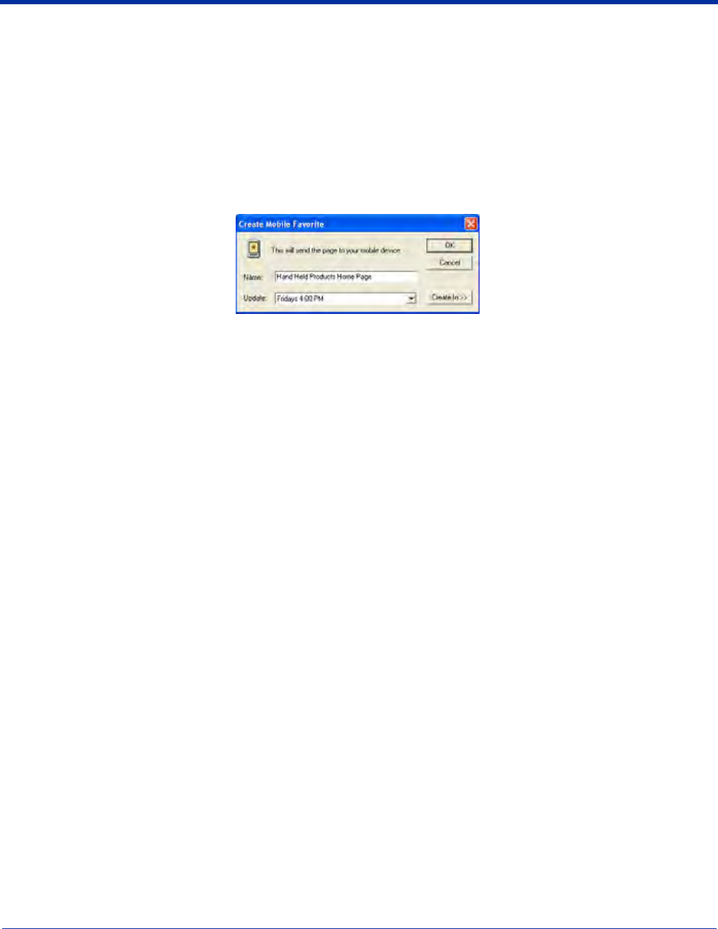
10 - 12 Dolphin® 9500 Series Mobile Computer User’s Guide - Preliminary Rev (d) 12/17/04
Note: Unless you mark a Favorite Link as a mobile favorite, only the link downloads to your terminal, and you will need to connect
to your ISP or network to view the content. For more information on synchronization, see ActiveSync Help on the desktop
computer.
Creating and Synchronizing Mobile Favorites
If you are using Microsoft Internet Explorer 5.0 or later on your desktop computer, you can download Mobile Favorites to the
terminal. Synchronizing mobile favorites downloads Web content to your device so that you can view pages while you are
disconnected from your ISP and desktop computer.
Use the Internet Explorer plug-in installed with ActiveSync to create mobile favorites
1. On your desktop computer, open Internet Explorer, click Tools > Create Mobile Favorite.
2. To change the link name, enter a new name in the Name box.
3. Optionally, in Update, select a desired update schedule.
4. Tap OK. Internet Explorer downloads the latest version of the page to your desktop computer.
5. If you want to download the pages that are linked to this mobile favorite, in Internet Explorer on the desktop computer, right-
click the mobile favorite and then click Properties. On the Download tab, specify the number of links down that you want to
download. To conserve memory, go only one level down.
6. Synchronize the terminal and desktop computer. Mobile favorites that are stored in the Mobile Favorites folder in Internet
Explorer are downloaded to the terminal.
If you did not specify an update schedule in Step 3, you will need to manually download content to keep the information updated
on your desktop computer and terminal. Before synchronizing, in Internet Explorer on your desktop computer, click Tools and
then Synchronize. You will see the last time content was downloaded to the desktop computer, and you can manually download
content if needed.
You can add a button to the Internet Explorer toolbar for creating mobile favorites. In Internet Explorer on your desktop computer,
click View, Toolbars, and then Customize.
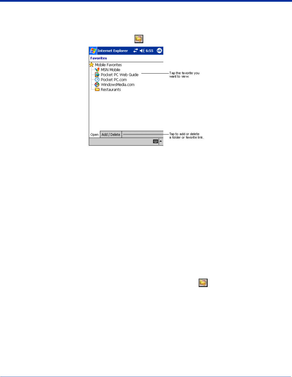
Dolphin® 9500 Series Mobile Computer User’s Guide - Preliminary Rev (d) 12/17/04 10 - 13
View Mobile Favorites and Channels on the Terminal
1. Access Pocket Internet Explorer.
2. Tap the Favorites button to display your list of favorites .
3. Tap the page you want to view.
You’ll see the page that was downloaded the last time you synchronized with your desktop computer. If the page is not on the
terminal, the favorite will be dimmed. You will need to synchronize with your desktop computer again to download the page to
the terminal, or connect to the Internet to view the page.
Mobile favorites take up storage memory on the terminal. To minimize the amount of memory used:
• In the settings for the Favorites information type in ActiveSync options, turn off pictures and sounds, or stop specific
mobile favorites from being downloaded to the terminal. For more information, see ActiveSync Help.
• Limit the number of downloaded linked pages. In Internet Explorer on the desktop computer, right-click the mobile
favorite you want to change and then Properties. On the Download tab, specify 0 or 1 for the number of linked pages
you want to download.
Using AvantGo® Channels
AvantGo is a free interactive service that provides access to personalized content and thousands of popular web sites. Subscribe
to AvantGo channels directly from the terminal. For more information, visit: http://avantgo.com/frontdoor/index.html.
To Sign Up for AvantGo
1. In ActiveSync options on the desktop computer, turn on synchronization for the AvantGo information type.
2. In Pocket Internet Explorer, tap the Favorites button to display your list of favorites .
3. Tap the AvantGo Channels link.
4. Tap Activate and follow the directions on the screen. Synchronize the terminal with your desktop computer and then tap the
My Channels button to complete the AvantGo setup.
5. When synchronization is complete, tap the AvantGo Channels link in your list of favorites to see a few of the most popular
channels. To add or remove channels, tap the Add or Remove link.
Pocket Word
Pocket Word works with Microsoft Word on your desktop computer to give you easy access to copies of your documents. You
can create new documents on the terminal, or you can copy and paste documents from your desktop computer. Synchronize
documents between your desktop computer and your device so that you have the most up-to-date content in both locations.
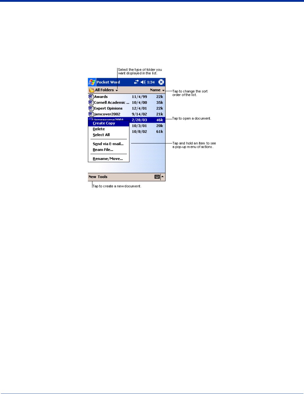
10 - 14 Dolphin® 9500 Series Mobile Computer User’s Guide - Preliminary Rev (d) 12/17/04
You can open only one document at a time; when you open a second document, you’ll be asked to save the first. You can save
a document you create or edit in a variety of formats, including Word (.doc), Pocket Word (.psw), Rich Text Format (.rtf), and
Plain Text (.txt).
Using Pocket Word
Pocket Word contains a list of the files stored on the terminal. Tap a file in the list to open it. To delete, make copies of, and send
files, tap and hold a file in the list. Then, select the appropriate action on the pop-up menu.
You can change the zoom magnification by tapping View > Zoom, and then selecting the percentage you want. Select a higher
percentage to enter text and a lower one to see more of your document.
If you’re opening a Word document created on a desktop computer, select Wrap to Window on the View menu so that you can
see the entire document.
Creating a Word File
To create a new file, tap Start > Programs > Pocket Word > New. A blank document appears. If you’ve selected a template for
new documents in the Options dialog box, that template appears with appropriate text and formatting already provided.
You can enter information in Pocket Word in one of two modes (typing on the SIP or keyboard and drawing), which are displayed
on the View menu.
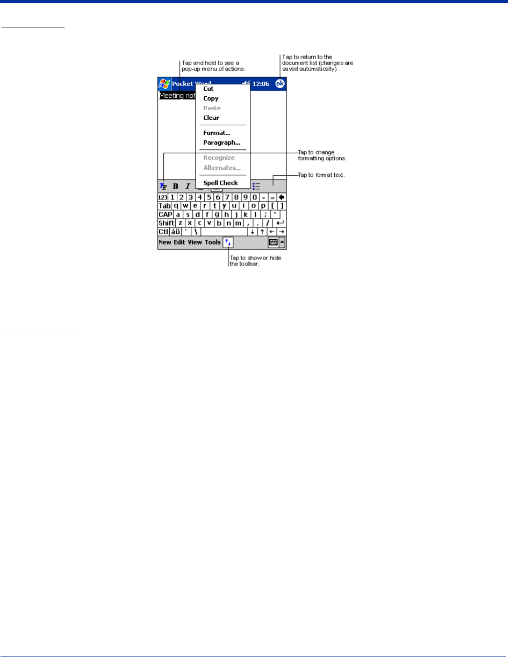
Dolphin® 9500 Series Mobile Computer User’s Guide - Preliminary Rev (d) 12/17/04 10 - 15
Typing Mode
Using the SIP or Dolphin keypad, enter typed text into the document.
To format existing text and to edit text, first select the text. You can select text as you do in a Word document, using your stylus
instead of the mouse to drag through the text you want to select. You can search a document to find text by tapping Edit and
then Find/Replace.
Drawing Mode
In drawing mode, use your stylus to draw on the screen. Gridlines appear as a guide. When you lift your stylus off the screen
after the first stroke, you’ll see a drawing box indicating the boundaries of the drawing. Every subsequent stroke within or touching
the drawing box becomes part of the drawing.
For more information on using Pocket Word, tap Start and then Help.
Pocket Excel
Pocket Excel works with Microsoft Excel on your desktop computer to give you easy access to copies of your workbooks. You
can create new workbooks on the terminal, or you can copy and paste workbooks from your desktop computer. Synchronize
workbooks between your desktop computer and the terminal so that you have the most up-to-date content in both locations.
You can open only one workbook at a time; when you open a second workbook, you’ll be asked to save the first. You can save
a workbook you create or edit in a variety of formats, including Pocket Excel (.pxl) and Excel (.xls).
Pocket Excel contains a list of the files stored on your device. Tap a file in the list to open it. To delete, make copies of, and send
files, tap and hold a file in the list. Then select the appropriate action from the pop-up menu. Pocket Excel provides fundamental
spreadsheet tools, such as formulas, functions, sorting, and filtering. To display the toolbar, tap View > Toolbar.
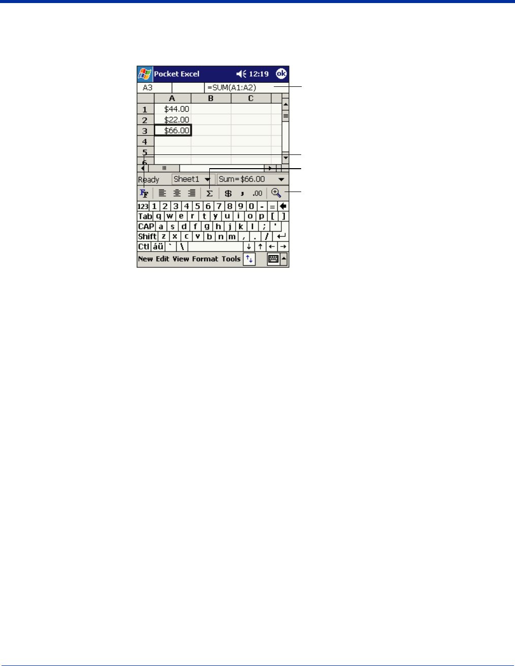
10 - 16 Dolphin® 9500 Series Mobile Computer User’s Guide - Preliminary Rev (d) 12/17/04
Creating an Excel File
To create a new file, tap Start > Programs > Pocket Excel > New. A blank workbook appears. If you’ve selected a template for
new workbooks in the Options dialog box, that template appears with appropriate text and formatting already provided.
If your workbook contains sensitive information, you can protect it with a password. To do so, open the workbook, tap Edit, and
then Password. Every time you open the workbook, you will need to enter the password, so choose one that is easy for you to
remember but hard for others to guess.
Tips for Working in Pocket Excel
• View in full-screen mode to see as much of your worksheet as possible. Tap View and then Full Screen. To exit full-screen
mode, tap Restore.
• Show and hide window elements. Tap View and then tap the elements you want to show or hide.
• Freeze panes on a worksheet. First select the cell where you want to freeze panes. Tap View > Freeze Panes. You might
want to freeze the top and left-most panes in a worksheet to keep row and column labels visible as you scroll through a sheet.
• Split panes to view different areas of a large worksheet. Tap View > Split. Then drag the split bar to where you want it. To
remove the split, tap View > Remove Split.
• Show and hide rows and columns. To hide a hidden row or column, select a cell in the row or column you want to hide. Then
tap Format,> Row or Column > Hide. To show a hidden row or column, tap Tools > Go To, and then type a reference that
is in the hidden row or column. Then tap Format > Row or Column > Unhide.
For more information on using Pocket Excel, tap Start > Help.
Cell content s appear he
re
as you enter them.
AutoSum button.
Format button.
Zoom button.
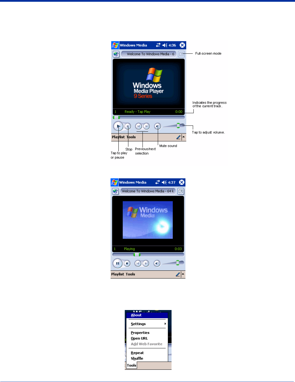
Dolphin® 9500 Series Mobile Computer User’s Guide - Preliminary Rev (d) 12/17/04 10 - 17
Windows Media Player for Pocket PC
Use Microsoft Windows Media Player (WMP) for Pocket PC to play digital audio and video files stored on the terminal. To switch
to Windows Media Player for Pocket PC, tap Start > Windows Media.
After a media file has been loaded, you can play, pause, stop, song advance/reverse, mute sound, or adjust volume.
Tools Menu
The tools menu allows you to perform several important functions.
About gives you information about the codecs used in your version of WMP.
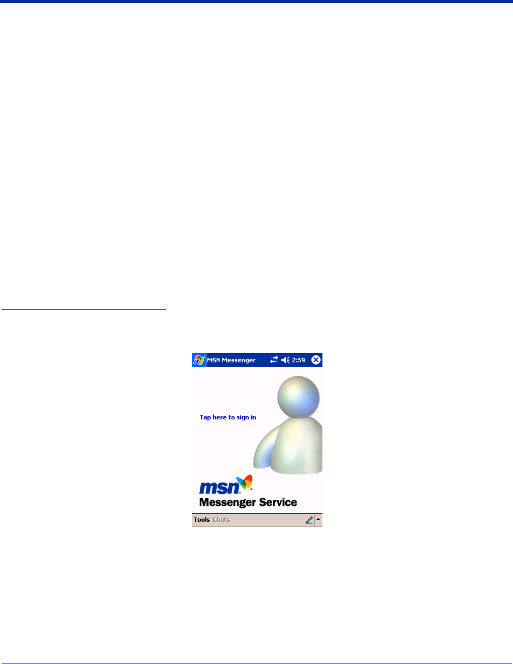
10 - 18 Dolphin® 9500 Series Mobile Computer User’s Guide - Preliminary Rev (d) 12/17/04
Settings allows you to configure several important aspects of WMP.
Properties gives a detailed listing of a media file's attributes.
Open URL allows you to open WMP-compliant media from a network or Internet resource.
Add Web Favorite adds a streaming media file that is currently playing to web favorites.
Repeat plays a playlist repeatedly.
Shuffle plays items in a playlist in a random order.
MSN Messenger
MSN Messenger is an instant messaging program that lets you:
• See who is online.
• Send and receive instant messages.
• Have instant message conversations with groups of contacts.
Note: To use MSN Messenger, you must have a Microsoft Passport™ account or a Microsoft Exchange e-mail account. You
must have a Passport to use MSN Messenger Service. If you have a Hotmail or MSN account, you already have a
Passport account. Sign up for a Microsoft Passport account at www.passport.com.
Setting Up
Before you can connect for the first time, you must enter the information from your Passport or Exchange account. After you set
up your account information on the terminal for the first time, you will go directly to login when you access MSN Messenger.
To Set Up an Account and Sign In
Note: Ensure that you are connected to the Internet (see Connections Tab on page 5-15).
1. Tap Start > Programs > MSN Messenger
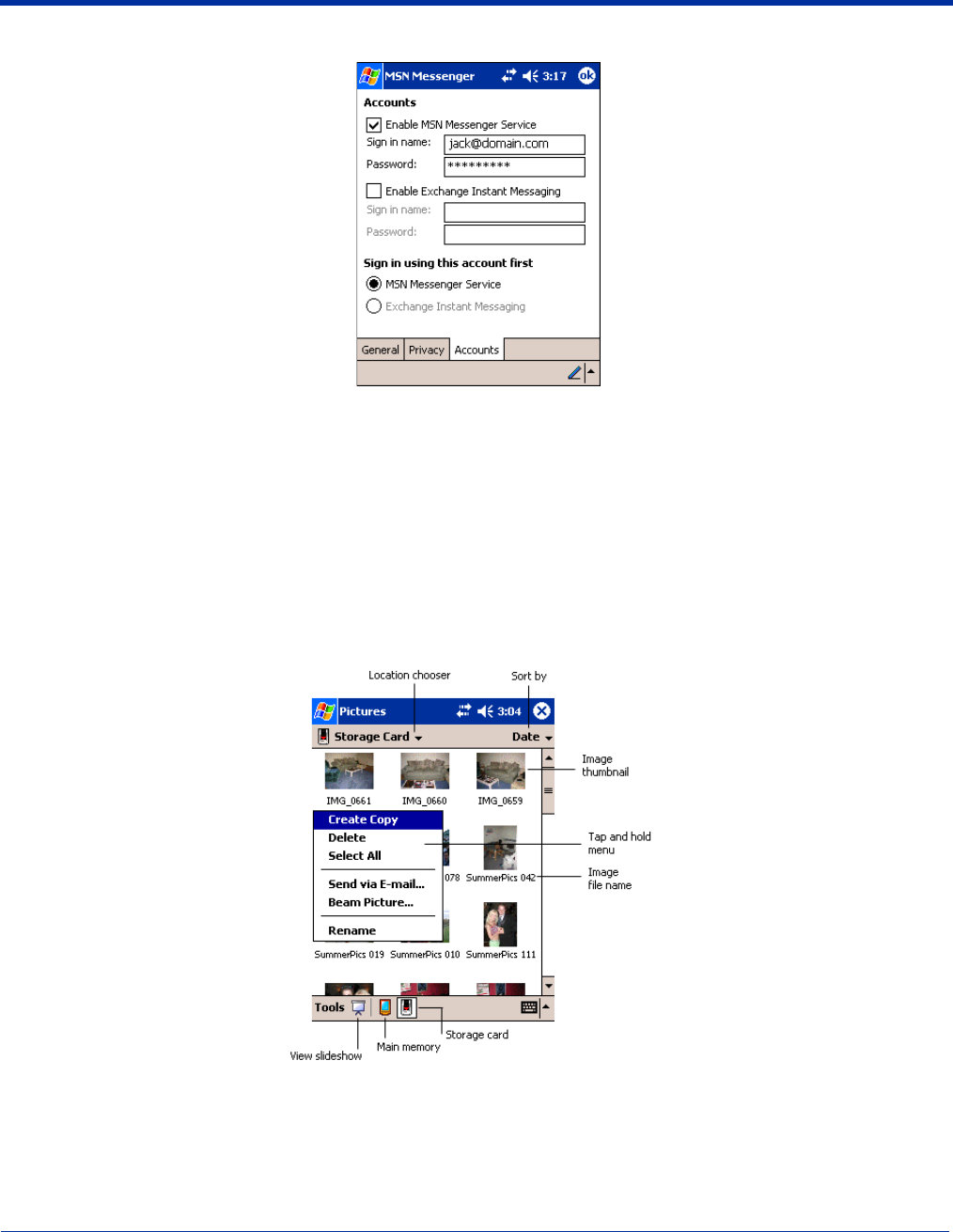
Dolphin® 9500 Series Mobile Computer User’s Guide - Preliminary Rev (d) 12/17/04 10 - 19
2. Tap Tools > Options > Account tab.
3. In the Accounts tab, enter your Passport or Exchange account information.
Be sure to indicate the service you’re using to connect - Messenger or Exchange.
4. When complete, tap OK. You are returned to the sign-in screen.
5. To sign in, tap the sign-in screen and enter your e-mail address and password.
Note: If you already use MSN Messenger, your contacts will show up on your device without being added again.
Pictures
Use Pictures to view JPEG pictures stored on the terminal or storage card.
To begin, tap Start > Programs > Pictures.
Choose to view main memory or storage card contents. By tapping and holding on an image, you can create a clone of that file,
delete that file, select all files, send file via e-mail, beam picture, or rename the image.

10 - 20 Dolphin® 9500 Series Mobile Computer User’s Guide - Preliminary Rev (d) 12/17/04
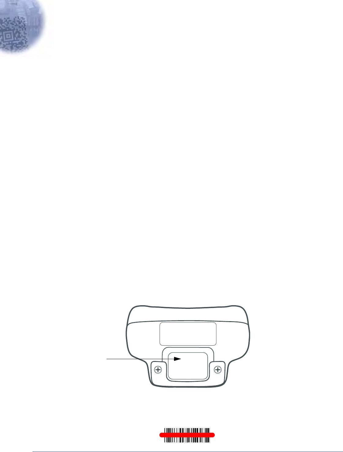
Dolphin® 9500 Series Mobile Computer User’s Guide - Preliminary Rev (d) 12/17/04 11 - 1
11
Dolphin 9501 and Dolphin 9551
Overview
As part of the Dolphin 9500 Series, the Dolphin 9551 and Dolphin 9501 terminals contain the same robust features, such as the
Windows Mobile platform and rugged ergonomics. In addition, the Dolphin 9501 and Dolphin 9551 offer laser engine support,
which enables you to scan and decode linear bar codes from greater distances.
The expanded scanning and decoding capabilities combined with the terminal’s durability make Dolphin 9551 and Dolphin 9501
terminals ideal for in-premise mobile application environments.
Laser Engine Options
Dolphin 9551 and Dolphin 9501 terminals may be equipped with one of the following SE 1200 laser engines:
High Performance (HP) The HP non-decoded engine reads
• 5 mil bar codes from 2.75 to 7 in (0.07 to 0.17 m) and
• 55 mil reflective bar codes from 5 to 50 in (.13 to 1.27 m).
Long Range (LR) The LR non-decoded engine reads
• 10 mil bar codes from 10 to 24 in (0.25 to .6 m) and
• 100 mil reflective bar codes from 66 to 232 in (1.67 to 5.9 m).
Advanced Long Range The ALR non-decoded engine reads
(ALR) • 13 mil bar codes from 18 to 39 in (0.45 to 1 m) and
• 100 mil reflective bar codes from 102 to 363 in (2.6 to 9.2 m).
Note: Dolphin 9501 and Dolphin 9551 terminals do not support image capture.
Bar Code Symbologies Supported
Laser engines support only the decoding of linear bar codes. For a complete list of these codes, see 1D Symbologies on page
2-6.
Laser Engine Location
The laser engine points straight out of the contoured casing on both the Dolphin 9501 and Dolphin 9551.
Aiming Options
Laser engines do not support omni-directional scanning. To achieve an optimal scan, center the red aiming beam across the bar
code horizontally as shown below.
Image
Engine
Window

11 - 2 Dolphin® 9500 Series Mobile Computer User’s Guide - Preliminary Rev (d) 12/17/04
Radio Options
Dolphin 9551 and Dolphin 9501 terminals can be configured with one or a combination of the following radios:
• 802.11b
• Bluetooth
Please note that 802.11b and Bluetooth radios are co-operational. For more information about radio operations, see The Radio
Manager on page 4-16.
Keyboard Options
Dolphin 9551 and Dolphin 9501 terminals can be configured with any of the Dolphin 9500 Series keyboards. For more
information, see Using the Keyboards on page 4-8.
Peripherals and Accessories
Because Dolphin 9551 and Dolphin 9501 terminals have the same mechanical connector (Mechanical Connector, page 3-9),
they are compatible with all Dolphin 9500 Series peripherals (Dolphin 9500 Series Peripherals, page 2-3) and accessories
(Dolphin 9500 Series Accessories, page 2-4). However, due to their different shape, both the Dolphin 9501 and Dolphin 9551
terminals have their own enclosures.
Note: The Dolphin 9551 requires the Dolphin 9550 Mobile Base to accommodate the handle.
Front Panel Features
Dolphin 9500 Series terminals contain the same front panel features; see Front Panel Features on page 3-2.
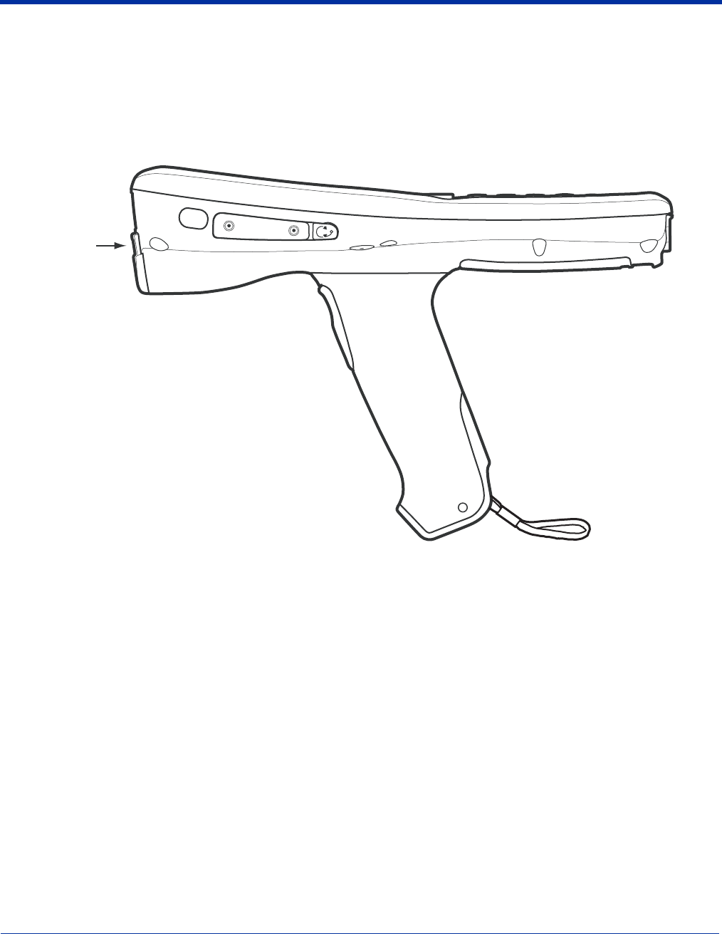
Dolphin® 9500 Series Mobile Computer User’s Guide - Preliminary Rev (d) 12/17/04 11 - 3
Dolphin 9551
The Dolphin 9551 terminal features the same integrated pistol grip as the Dolphin 9550 for secure and versatile handling in scan-
intensive applications. The front end of the bottom housing accommodates the laser engine.
Side Panel
The following graphic shows the left, side panel of the Dolphin 9551.
Note: Just like the Dolphin 9550, the stylus is stored in the pistol-grip handle.
,ASER
%NGINE
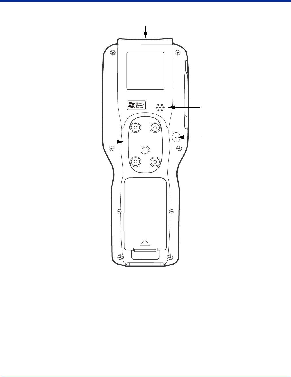
11 - 4 Dolphin® 9500 Series Mobile Computer User’s Guide - Preliminary Rev (d) 12/17/04
Back Panel
Speaker
Laser Engine
Microphone
Pistol-Grip Handle
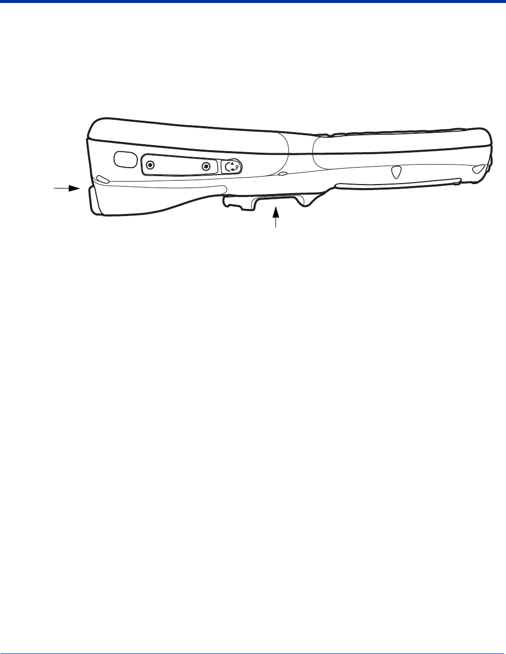
Dolphin® 9500 Series Mobile Computer User’s Guide - Preliminary Rev (d) 12/17/04 11 - 5
Dolphin 9501
The Dolphin 9501 contains a powerful laser engine inside a solid, flashlight form factor.
Side Panel
Like the Dolphin 9551, the front end of the bottom housing accommodates the laser engine.
Finger Saddle
Laser
Engine
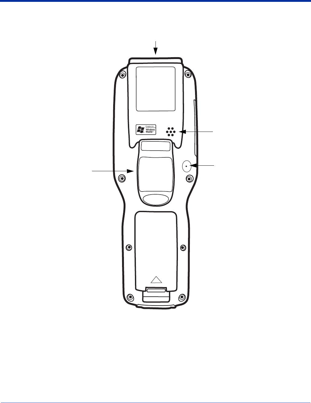
11 - 6 Dolphin® 9500 Series Mobile Computer User’s Guide - Preliminary Rev (d) 12/17/04
Back Panel
For secure handling in the field, the back panel of the Dolphin 9501 contains a finger saddle.
Speaker
Laser Engine
Microphone
Finger Saddle
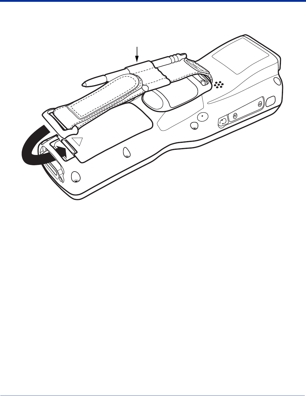
Dolphin® 9500 Series Mobile Computer User’s Guide - Preliminary Rev (d) 12/17/04 11 - 7
Hand Strap and Stylus
The hand strap is attached to the finger saddle and contains two stylus loops, one on either side of hand strap.
Note: By contrast, on the Dolphin 9500, the hand strap is attached to the top portion of the back panel (Hand Strap Attachment,
page 3-4) and the stylus is stored in a slot in the back panel (Stylus (in slot), page 3-4).
Bottom Panel Features
All Dolphin 9500 series terminals contain the same industrial-grade, mechanical connector on the bottom panel; see Bottom
Panel Features on page 3-9.
Stylus in the loop on the hand strap

11 - 8 Dolphin® 9500 Series Mobile Computer User’s Guide - Preliminary Rev (d) 12/17/04

Dolphin® 9500 Series Mobile Computer User’s Guide - Preliminary Rev (d) 12/17/04 12 - 1
12
Dolphin 9500 Series HomeBase
Overview
As the hub of your Dolphin 9500 Series system, the Dolphin HomeBase charging and communication cradle supports both RS-
232 and USB communications, which make it able to interface with the majority of PC-based enterprise systems. When a terminal
is seated in the HomeBase, its main battery pack charges in less that four hours.
Power
The HomeBase completes a full charge of the main battery pack in less than four hours. The HomeBase also provides power to
the intelligent battery charging system in all Dolphin terminals that senses when a full charge has been achieved and switches
to a trickle charge to maintain the full charge.
Communications
Reliable data communications at speeds of up to 115k baud can be transmitted by the HomeBase through the RS-232 serial
port. Using the full-speed USB port, the data transmission rate goes up to 12 Mbps.
HomeBases cannot be physically connected to each other - sometimes referred to as “daisy-chained” - but can be networked
together via a serial or USB hub.
Convenient Storage
Intelligent battery charging makes the Dolphin HomeBase a safe and convenient storage receptacle for your Dolphin terminal.
Capacity
The Dolphin HomeBase holds one terminal and features an auxiliary battery well behind the terminal well that can charges a
battery pack independently of the terminal well. This means that one HomeBase can charge two battery packs: the one installed
in the terminal and a spare.
Use only Dolphin 9500 Series peripherals, power cables, and power adapters. Use of peripherals, cables, or power
adapters not sold/manufactured by Hand Held Products will void the warranty and may damage the terminal.
Use only the Li-ion battery packs provided by Hand Held Products. The use of any battery pack not sold/manufactured
by Hand Held Products in the Dolphin 9500 Series terminals will void your warranty and may result in damage to the
Dolphin terminal or battery.
!
!
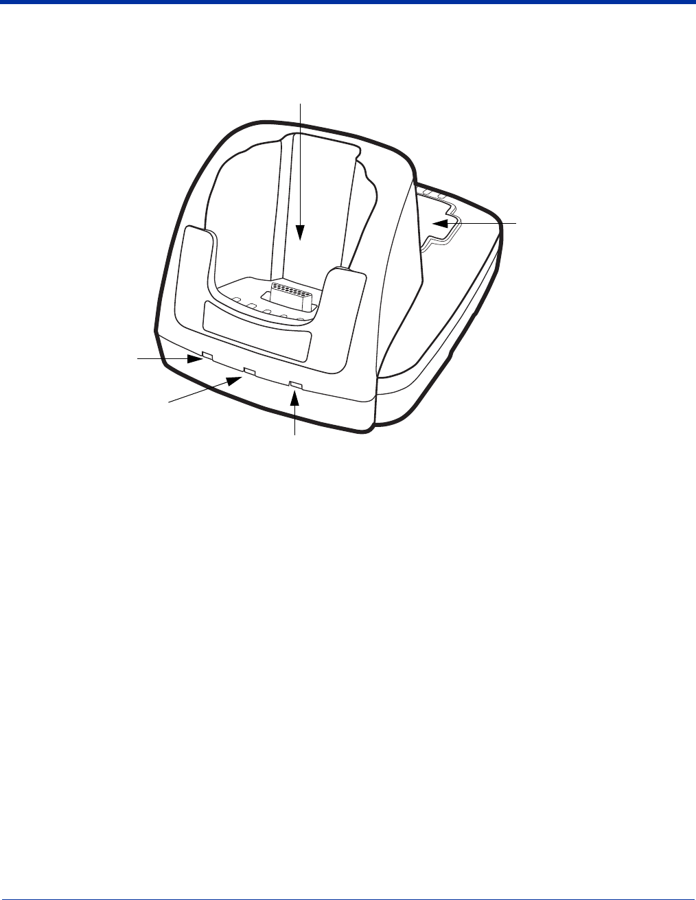
12 - 2 Dolphin® 9500 Series Mobile Computer User’s Guide - Preliminary Rev (d) 12/17/04
Dolphin 9500 Series HomeBase Parts and Functions
Front Panel
Terminal Well
Place the Dolphin terminal in this well to communicate with a host device, power the terminal, and charge its battery
pack. If the host device is a desktop computer that uses ActiveSync, synchronization begins immediately. While seated
in the terminal well, the main battery installed in the terminal charges. The HomeBase completely charges a battery
pack in less than four hours.
Auxiliary Battery Well
See Auxiliary Battery Well on page 12-3.
DOCK LED
Turns solid green when the Dolphin terminal is properly seated in the Dolphin HomeBase. When this light is on, the
terminal is connected to the base.
AUX Battery LED
Indicates status of the battery charging in the auxiliary battery well.
To see the auxiliary battery well, see Rear Panel on page 12-3.
For information about charging a battery in the auxiliary battery well, see page 12-5.
This color means…
Orange
The auxiliary battery is charging.
Green
The auxiliary battery has completed charging and is ready for use.
Terminal Well
DOCK LED
Auxiliary Battery Well
AUX Battery LED
COMM LED
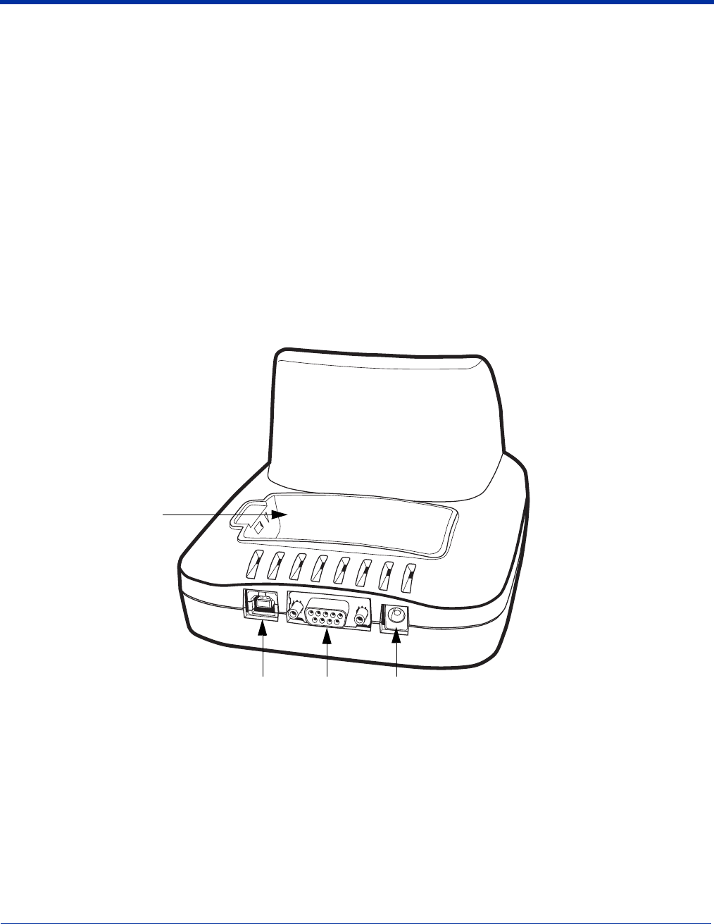
Dolphin® 9500 Series Mobile Computer User’s Guide - Preliminary Rev (d) 12/17/04 12 - 3
COMM LED
This is the communication LED. It indicates the status of data transfer between the Dolphin terminal and the host device.
The color of this LED differs if the HomeBase is using the serial or USB port connection.
If using the serial port
If using the USB port
Rear Panel
Auxiliary Battery Well
The HomeBase enables you to charge an additional Li-ion battery pack independently of the terminal well. This feature
ensures that you can always have a fully-charged battery for your Dolphin terminal. See Charging a Spare Battery in
the Auxiliary Battery Well on page 12-5.
USB Port
This USB Port is full-speed and 2.0 compliant. Using a USB cable, you can connect the HomeBase to a peripheral
device, such as a desktop computer or printer. When the Dolphin terminal is seated in the terminal well, it is connected
to the peripheral device via the HomeBase. The USB port on the HomeBase requires that you use ActiveSync 3.7 or
higher.
This color means…
Red
Serial data is being sent from the Host Device to the Dolphin
HomeBase.
Green
Serial data is being sent from the Dolphin HomeBase to the Host Device.
Orange
Serial data is being sent at high data rates.
This color means…
Green LED
A USB Connection is established with the host computer.
Auxiliary Battery Well
DC Power JackRS-232 PortUSB Port
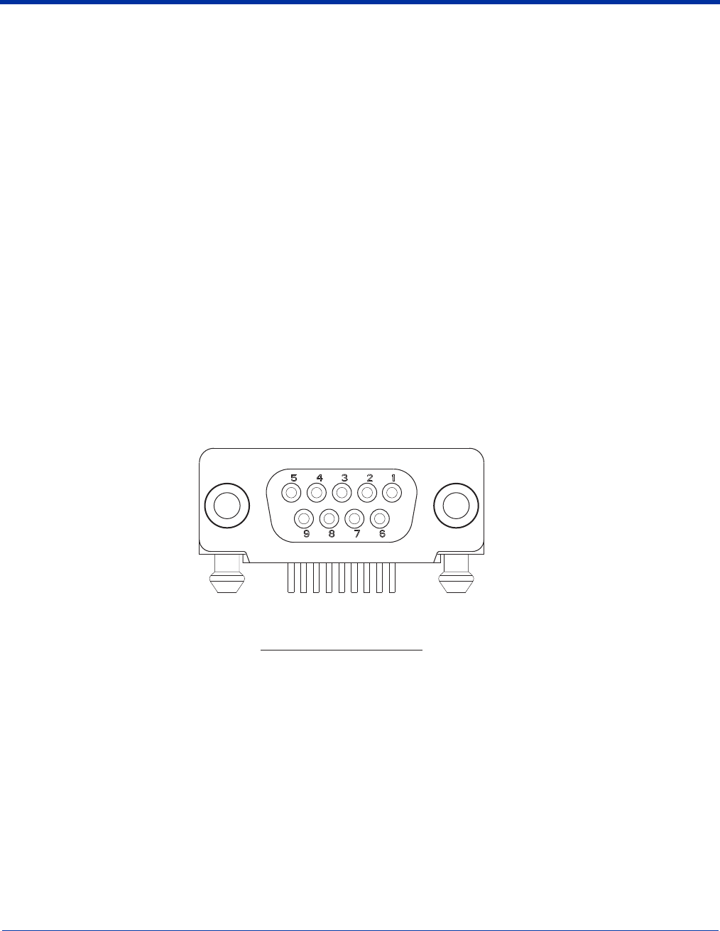
12 - 4 Dolphin® 9500 Series Mobile Computer User’s Guide - Preliminary Rev (d) 12/17/04
RS-232 Port
Use a 9-pin, RS-232 cable from Hand Held Products to connect this port to a peripheral device for RS-232 data
communication. For more information, see HomeBase Serial Connector on page 12-4.
DC Power Jack
Use a power cable from Hand Held Products to supply power to this power jack. For more information, see Powering
the HomeBase on page 12-4.
Powering the HomeBase
The terminal requires 9.5 Volts DC input for communications and battery charging; the Hand Held Products’ power cable contains
a power adapter that converts the power source voltage accordingly. Only the power adapter cable from Hand Held Products
converts the voltage appropriately.
Hand Held Products recommends that you leave the Dolphin HomeBase connected to its power source at all times, so that it is
always ready to use.
1. Connect the Hand Held Products’ power cable to the DC jack on the rear panel of the HomeBase.
2. Connect the Hand Held Products’ power cable to the power adapter.
3. Plug the power adapter cable into the power source. The HomeBase is now powered.
HomeBase Serial Connector
The following diagram displays the pin diagram of the serial connector of the HomeBase.
Note: Signals referenced are for a DTE device. The HomeBase is at a right-angle to the printed circuit board (PCB). The ninth
pin has a ring indicator (RI).
Pin # Description
1 Internal Jumper to Pin 6
2 TXD
3 RXD
4 DSR
5 GND
6 DTR
7 CTS
8RTS
9RI
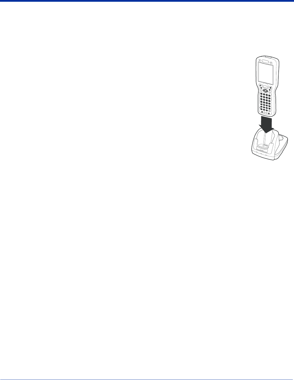
Dolphin® 9500 Series Mobile Computer User’s Guide - Preliminary Rev (d) 12/17/04 12 - 5
Charging the Main Battery
The Dolphin HomeBase powers the terminal and fully charges its main battery pack in less that four hours. The HomeBase
contains an intelligent battery charging system that protects the battery from being damaged by overcharging; the unit senses
when a battery pack is fully charged and automatically switches to a trickle charge that maintains the battery at full capacity.
Therefore, Dolphin terminals may be stored in the HomeBase without damage to the terminals, battery packs, or peripherals.
To check battery power, use the Power system setting; see Power on page 5-10.
For more information about Hand Held Products Li-ion batteries, see Batteries on page 3-10.
To Power a Terminal and Charge its Main Battery
1. Install the battery pack in the terminal; see Install the Main Battery Pack on page 2-7.
1. Connect the HomeBase to the power supply provided by Hand Held Products.
2. Slide the terminal into the terminal well until the Dock LED lights green to indicate that the terminal is
properly seated.
3. The battery pack begins charging.
Charging a Spare Battery in the Auxiliary Battery Well
The auxiliary battery well located on the back of the HomeBase charges a spare battery independently of
the terminal well. The Aux Battery LED on the front panel indicates the status of the battery in this well.
Charge time is less than four hours; see Auxiliary Battery Well on page 12-3.
1. Insert the end of the battery without the locking tab into the bottom of the auxiliary well opening.
2. Snap the battery into place with a hinging motion. The Aux Battery LED lights orange.
3. Use the AUX Battery LED to monitor charging progress.
Communications
There are two types of communication available: USB and RS-232.
USB
The HomeBase also supports USB communications via the USB port located on the back. The HomeBase acts as a USB device
by interfacing the USB signals of the Dolphin terminal to the USB of the host computer. Using a standard USB cable, the
HomeBase’s USB interface allows the Dolphin terminal to communicate with a personal computer or to be networked through a
USB hub.
RS-232
The HomeBase supports RS-232 communications via the RS-232 Communications Port located on the back of the device. This
port enables the Dolphin terminal to communicate to a personal computer, modem, or any RS-232 device using a standard serial
cable and communications software.
Note: The HomeBase should have only one type of interface cable connected at a time, either USB or RS-232. You must be
using ActiveSync, version 3.7 or higher.
DOCK
AUXBATTERY
COMM
SCAN
ESC
TAB
SFT
ABC
EFG
IJK
MNO
S
R
Q
UVW
YZ
D
H
L
P
T
X
NUM
ENT
123
789
456
;:
*
@
F1F2F3F4
F5F6F7F8
STARTINSBKSPDEL
CTRLALT
SEND
END
POWER
V
O
L
P
G
V
O
L
P
G
+
+
-0
,
SP
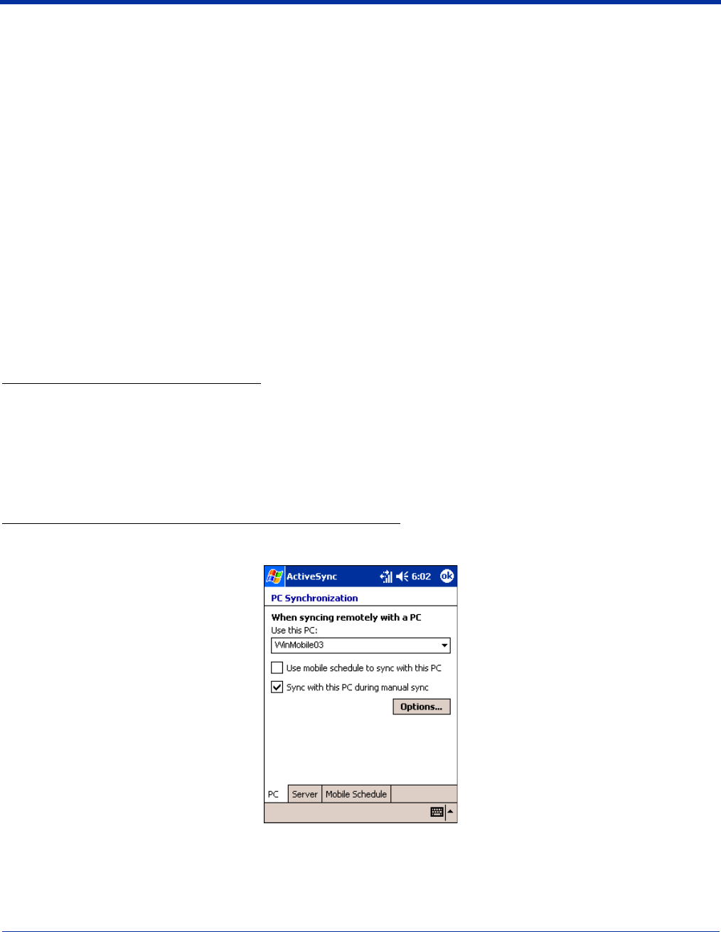
12 - 6 Dolphin® 9500 Series Mobile Computer User’s Guide - Preliminary Rev (d) 12/17/04
Equipment Requirements
To use the HomeBase for communications, you need the following equipment:
• A HomeBase powered by a power cable and power adapter cable from Hand Held Products
• For RS-232 communications, a Serial cable
• For USB communications, a USB cable
Setting up the HomeBase for USB Communication
Dolphin 9500 Series terminals support USB communications out of the box.
Required Equipment:
• HomeBase with power supply
• USB Cable
• ActiveSync v3.7 or above
• Windows® 98 second edition*, Windows® Me, Windows® 2000, or Windows® XP computer.
Note: The HomeBase does not support Windows
NT® when using a USB connection.
This is because Windows
NT
does not
support USB
.
*Windows® 98 second edition provides full USB support.
To Install the HomeBase Using USB
Note: You must be using ActiveSync 3.7 or higher.
1. Plug in the power supply and connect it to the back of the HomeBase.
2. Plug the USB cable into the back of the HomeBase.
3. At this point, the hardware is installed and operating. You may need to reboot your PC to complete the installation process.
Setting up the Terminal for ActiveSync Communications
1. On the terminal, tap Start > ActiveSync > Tools > Options. Activesync opens displaying the PC tab.
2. In the Use this PC drop-down list, select the name of the host PC.
3. Select Sync with this PC during manual sync to indicate that the terminal syncs with the selected host PC when
synchronization is run from the terminal.
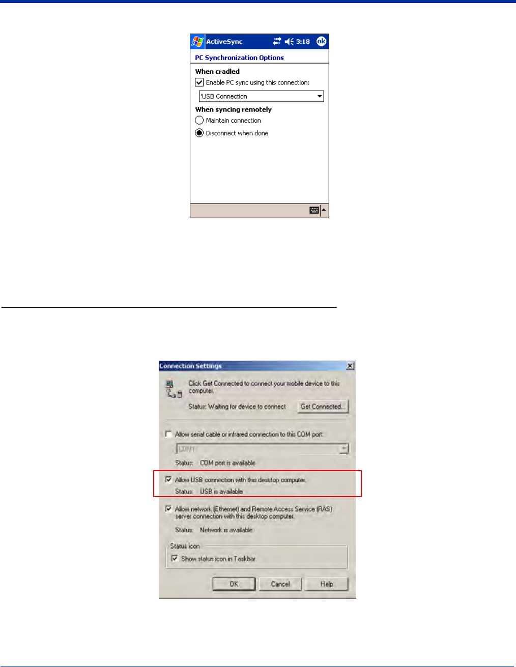
Dolphin® 9500 Series Mobile Computer User’s Guide - Preliminary Rev (d) 12/17/04 12 - 7
4. Tap Options.
5. Select Enable PC sync using this connection, then select ‘USB Connection from the drop-down list.
6. Tap OK.
7. Place the Dolphin terminal in the HomeBase. The Dolphin terminal attempts to start an ActiveSync connection with the
desktop computer automatically.
Setting up the Desktop Computer for ActiveSync Communications
After the USB HomeBase is installed, you can use ActiveSync to connect to a Dolphin terminal that is properly seated in the
HomeBase. These instructions assume that ActiveSync v3.7 is installed on your PC.
The ActiveSync Connection Settings must be set as the following graphic indicates.
The Allow USB connection with this desktop computer box must be checked. Do not check the serial cable box.

12 - 8 Dolphin® 9500 Series Mobile Computer User’s Guide - Preliminary Rev (d) 12/17/04
Communicating with the Dolphin 9500 Series Terminal
To initiate communications between the Dolphin 9500 Series terminal and peripheral, complete these steps:
1. Insert the Dolphin terminal into the terminal well of the HomeBase.
• The DOCK LED illuminates green. If the DOCK LED does not illuminate, make sure that the terminal is properly seated.
You may need to remove and re-insert the terminal.
• The Dolphin terminal activates; if the power is off, the terminal automatically powers on. If the terminal does not power on,
verify that the Hand Held Products power supply is properly connected to the cradle and plugged into a functioning outlet.
• The Dolphin terminal automatically opens ActiveSync to establish a connection.
2. The HomeBase can now transfer data between the terminal and the host device. If communication does not occur, check the
port connections to ensure that the cradle is correctly configured.
Setting up the HomeBase for RS-232 Communications
Connecting the Cables
Connect the HomeBase to the host computer or other device by plugging an RS-232 serial cable into the RS-232
Communications Port on the rear of the HomeBase. The wiring of your cable depends on whether the other device is set up as
a Data Communications Equipment (DCE) or Data Terminal Equipment (DTE) device.
The HomeBase Communication Port is configured as a DCE device. To communicate with a DCE device, use either a null
modem adapter in line with a standard RS-232 cable, or a null-modem serial cable. To communicate with a DTE device such as
a computer, use a standard (or straight-through) RS-232 cable.
You can make your own cables by following the pin configuration in the chart below. To do so, you must determine if your host
RS-232 device is 9-pin or 25-pin, and whether it is configured as a DCE or DTE device.
RS-232 Pin Configuration
Note: The HomeBase cannot be daisy-chained.
HomeBase /Host Port
(DCE) IBM AT DB9
(DTE) IBM XT
DB25 (DTE) Modem DB25
(DCE)
Pin / Input Signal
2 / (RD) 2 3 2
3 / (TD) 3 2 3
5 / (SG) 5 7 7
4 / (DTR) 420 6
6 / (DSR) 6 6 20
7 / (RTS) 7 4 5
8 / (CTS) 8 5 4

Dolphin® 9500 Series Mobile Computer User’s Guide - Preliminary Rev (d) 12/17/04 12 - 9
Setting up the Terminal for ActiveSync Communications
1. On the terminal, tap Start > ActiveSync > Tools > Options. Activesync opens displaying the PC tab.
2. In the Use this PC drop-down list, select the name of the host PC.
3. Select Sync with this PC during manual sync to indicate that the terminal syncs with the selected host PC when
synchronization is run from the terminal.
4. Tap Options.
5. Under When cradled, select Enable PC sync using this connection, and select ‘115200 Default from the drop-down list.
‘115200 baud is recommended for RS-232 communication.
6. Tap OK.
7. Place the Dolphin in the HomeBase. The terminal attempts to start an ActiveSync connection with the desktop computer
automatically.
Setting up the Desktop Computer for ActiveSync Communications
ActiveSync must be installed and configured for RS-232 on the desktop computer to sync successfully with a Dolphin terminal
configured for RS-232 communication.
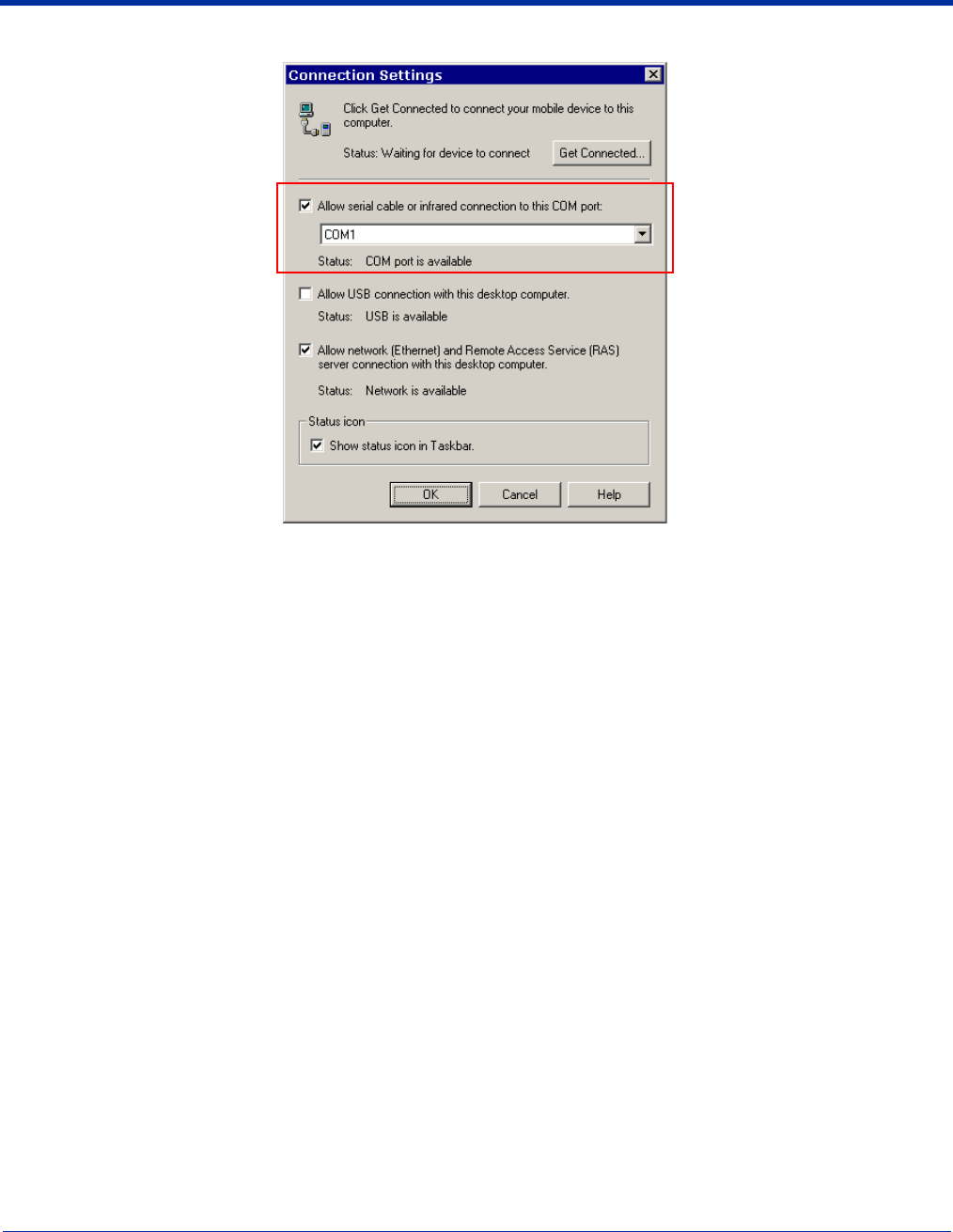
12 - 10 Dolphin® 9500 Series Mobile Computer User’s Guide - Preliminary Rev (d) 12/17/04
The following graphic displays the correct ActiveSync Connection Settings on the desktop computer for an RS-232 connection.
Note: You can have the USB connection box checked in addition to the serial cable box without affecting processing. However,
you would most likely use one or the other.
Verifying Communication
You can verify that the USB driver is functioning by watching the COMM LED on the USB HomeBase. When the COMM LED
illuminates solid green, the HomeBase is communicating with the host device.
Verifying Data Transfer
The COMM LED flashes when data is being transferred via the HomeBase. For an RS-232 connection, the COMM LED flashes
red and green. For a USB connection, the COMM LED flashes green.
Mounting the HomeBase
Set the Dolphin HomeBase on a dry, stable surface, such as a desktop or workbench near an electrical outlet. Be sure to provide
enough workspace with good lighting for the user to view and operate the Dolphin terminal while it is in the HomeBase.
When choosing a location, bear in mind that:
• the mounting location must allow users easy access to the Auxiliary Battery Well, and
• the serial and USB ports as well as the power jack face straight out of the rear panel, and you will most likely want easy access
to them in the future.
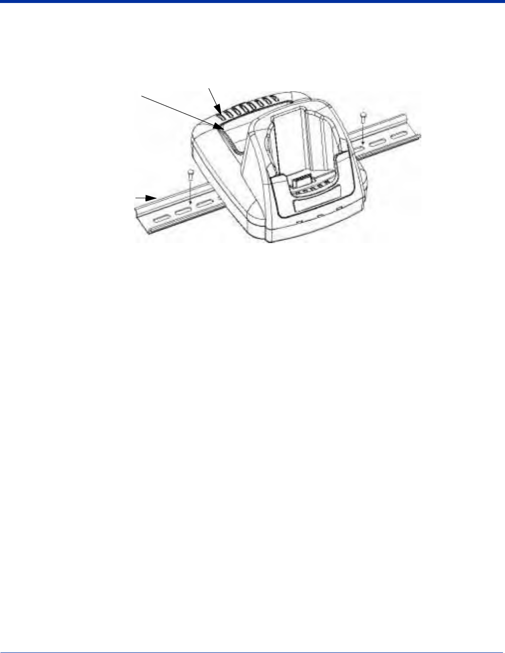
Dolphin® 9500 Series Mobile Computer User’s Guide - Preliminary Rev (d) 12/17/04 12 - 11
Desk Mounting
Dolphin charging/communication cradles have a DIN rail (7.5 X 35 mm) slot on the bottom to allow for secure desk attachment
of the unit if desired.
To mount the HomeBase, you slide the DIN rail slot along the bottom panel and secure it. Then, using the appropriate nuts and
bolts, secure the DIN rail to the desk or flat surface.
Auxiliary Battery Well
Serial and USB port location (not in view)
DIN Rail (7.5 X 35 mm)
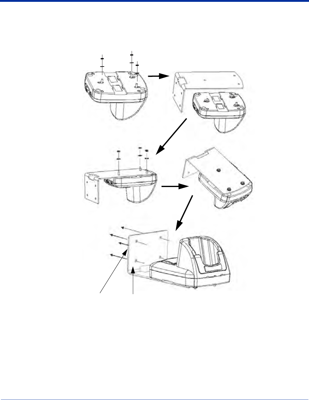
12 - 12 Dolphin® 9500 Series Mobile Computer User’s Guide - Preliminary Rev (d) 12/17/04
Wall Mounting
You can purchase a wall mount kit that contains
• a mounting bracket,
• three screws, and
• six washer/nut sets.
The back wedge of the mounting bracket contains an open slot for the power and communications cables. There is an extra
space between this slot and the rear panel of the HomeBase to allow easy access to the power and communications ports. For
more details on both ports, see Rear Panel on page 12-3.
Turn the secured
HomeBase righ
t
side up.
Attach the
bottom panel to
the mounting
bracket; match
the holes to the
secured screws
.
4.
2.
Back wedge Open slot for cords
Insert a screw into the
round end of each screw
slot on the bottom panel.
Slide each screw towards
the narrow end of the slot.
Then, use a washer/nut set
on each screw to secure
the screw in the slot.
Use the remaining washer/
nut sets to secure the
mounting brackets to the
bottom panel.
Secure the back wedge of
the mounting brackets to a
stable vertical surface.
1.
3.
5.

Dolphin® 9500 Series Mobile Computer User’s Guide - Preliminary Rev (d) 12/17/04 13 - 1
13
Dolphin 9500 Series Mobile Base
Overview
The Dolphin Mobile Base charging and communication cradle is designed specifically for in-premise and in-transit data collection
applications. It features a flexible mounting bracket, a cigarette lighter adapter, and a power cable to adapt it to your environment.
When a terminal is seated in the Mobile Base, its main battery pack charges in less than four hours. The serial connector supports
RS-232 communication and power out to peripheral devices, such as hand held scanners.
As the hub of your Dolphin 9500 Series mobile data collection system, the Mobile Base performs three important functions:
charging, communications, and storage.
Charging
The Dolphin Mobile Base completes a full charge of the main battery pack in less than four hours. The Mobile Base also provides
power to the intelligent battery charging system in all Dolphin terminals that senses when a full charge has been achieved and
switches to a trickle charge to maintain the full charge.
Communications
The Mobile Base transmits data to other devices at speeds of up to 115K baud via its RS-232 serial port.
Convenient Storage
Intelligent battery charging makes the Mobile Base a safe and convenient storage receptacle for your Dolphin terminal.
Capacity
The Mobile Base holds one terminal.
Use only Dolphin 9500 Series peripherals, power cables, and power adapters. Use of peripherals, cables, or power
adapters not sold/manufactured by Hand Held Products will void the warranty and may damage the terminal.
Use only the Li-ion battery packs provided by Hand Held Products. The use of any battery pack not sold/manufactured
by Hand Held Products in Dolphin 9500 Series terminals will void your warranty and may result in damage to the Dolphin
terminal or battery.
!
!
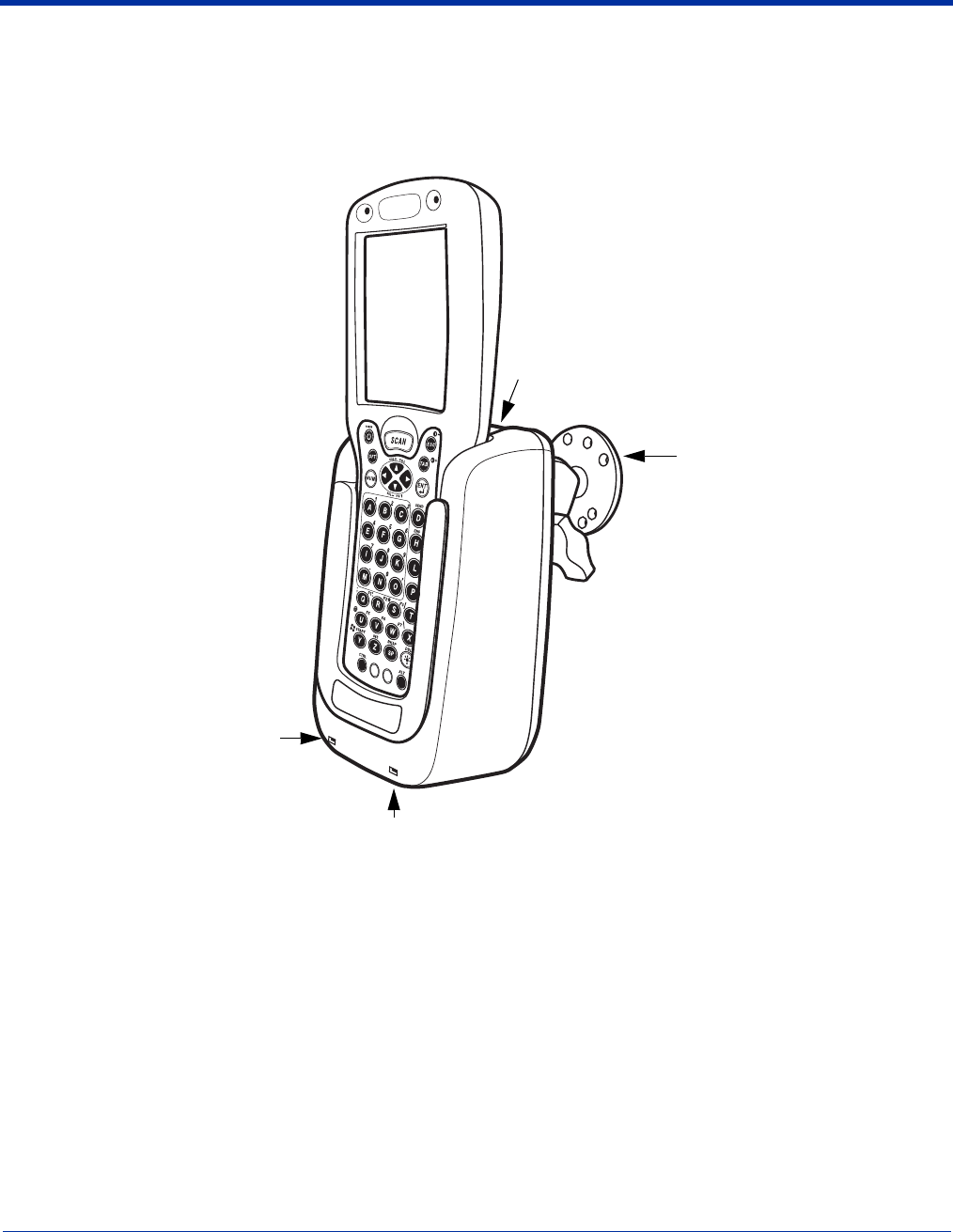
13 - 2 Dolphin® 9500 Series Mobile Computer User’s Guide - Preliminary Rev (d) 12/17/04
Mobile Base Parts and Functions
Front Panel
The front panel of the Mobile Base has one slot. The following graphic features the Mobile Base with the Dolphin 9500 inserted
into the terminal well.
Terminal Well Place the terminal in this well to communicate with a host device and charge the main battery pack.
Mounting Brackets Use these to mount the Mobile Base to a fixed location.
DOCK LED Illuminates solid green when the Dolphin terminal is properly seated in the terminal well.
COMM LED Indicates the status of data transfer between the host device and the Dolphin terminal
COMM LED color Indicates that…
Red Data is being sent from the Host Device to the Dolphin Mobile Base.
Green Data is being sent from the Dolphin Mobile Base to the Host Device.
Orange Data is being sent at high data rates.
DOCK
COMM
Terminal Well
COMM LED
Mounting
Brackets
DOCK LED
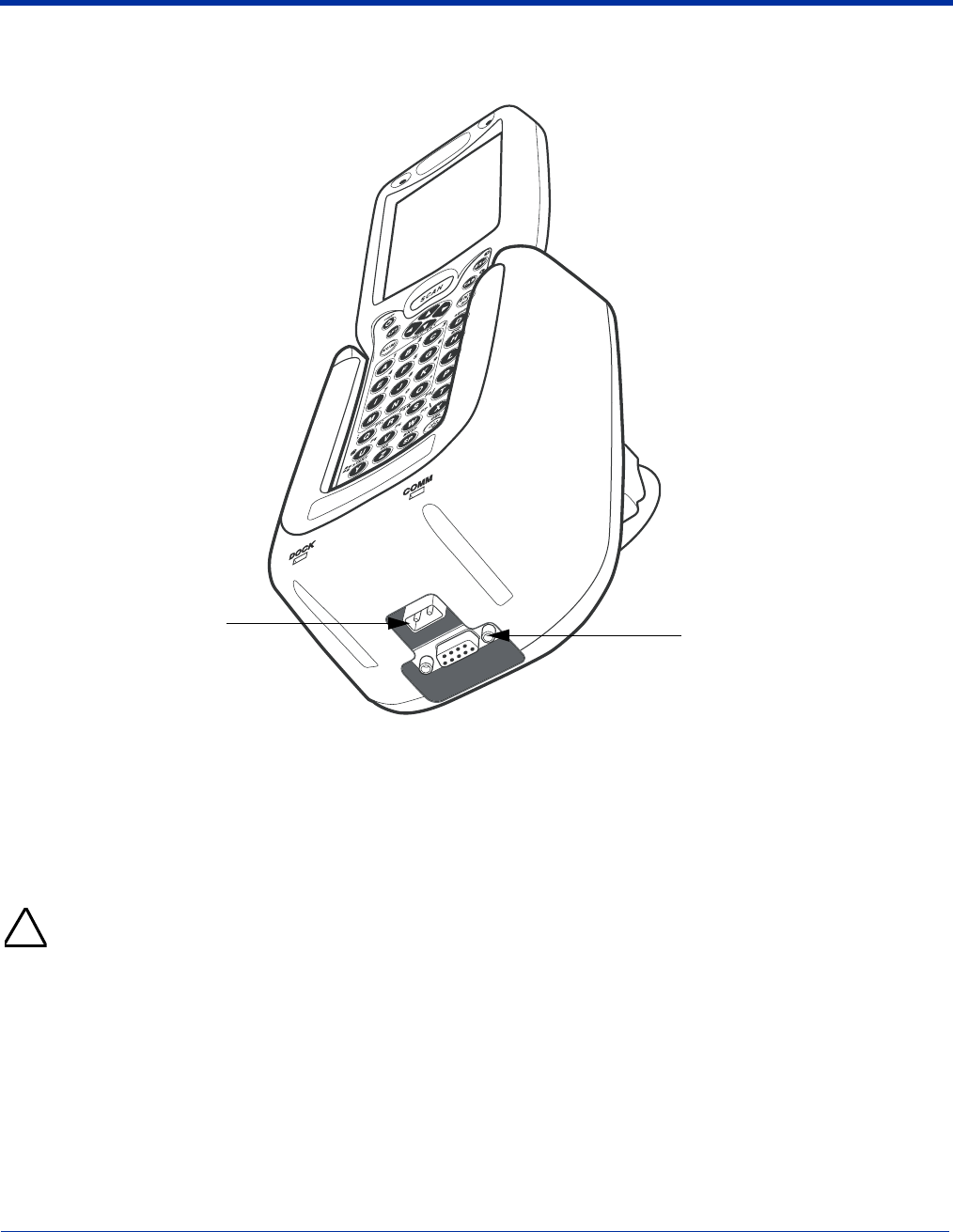
Dolphin® 9500 Series Mobile Computer User’s Guide - Preliminary Rev (d) 12/17/04 13 - 3
Bottom Panel
The power supply and RS-232 connectors are located on the bottom of the unit.
Power Supply Connector
Use this connector to attach a Hand Held Products power cable to the Dolphin 9500 Series Mobile Base. The Mobile
Base can be powered by an external DC power source of between 11 VDC to 48 VDC.
To run on vehicle power, you can use the 12 VDC cable or 24 VDC cable option. The appropriate cable comes with the
kit you ordered. The 12 VDC cable can be used with a cigarette lighter outlet. The 24 VDC, pigtail cable can be used to
“hard-wire” into the vehicle power bus.
Verify that the power source is always within the specified range and observe correct input voltage polarity. An improper
input voltage range (above the 48 VDC maximum) or reverse polarity could damage the power conversion circuitry.
RS-232 Communications Port
Use a standard serial cable to connect the unit to a host device via RS-232; see Mobile Base Serial Connector on page
13-8.
RS-232
Communications
Port
Power Supply
Connector
!

13 - 4 Dolphin® 9500 Series Mobile Computer User’s Guide - Preliminary Rev (d) 12/17/04
Powering the Dolphin Terminal
When seated in a Mobile Base that is connected to the appropriate power source, the Dolphin terminal receives the power to
charge its main battery and run its internal circuitry. Keep the Mobile Base plugged into the power source so that the Dolphin
terminal battery pack stays fully charged.
For more information about powering the Mobile Base, see Powering the Dolphin Mobile Base on page 13-6.
Charging the Dolphin Terminal
The Mobile Base supplies charging power to the Dolphin terminal so that the terminal can monitor the charging of its battery pack.
This charging method protects the battery from being damaged by overcharging. Therefore, the Dolphin terminal may be stored
indefinitely in the Mobile Base without damage to the terminal, the battery pack, or the Mobile Base.
To charge a Dolphin terminal, complete these steps:
1. Insert a battery pack into the Dolphin terminal.
2. Slide the terminal, imager window up and the LCD visible, into the terminal well of the Mobile Base until it stops.
3. When the Dolphin terminal is properly seated, the DOCK LED on the Mobile Base illuminates solid green. The terminal
begins charging automatically.
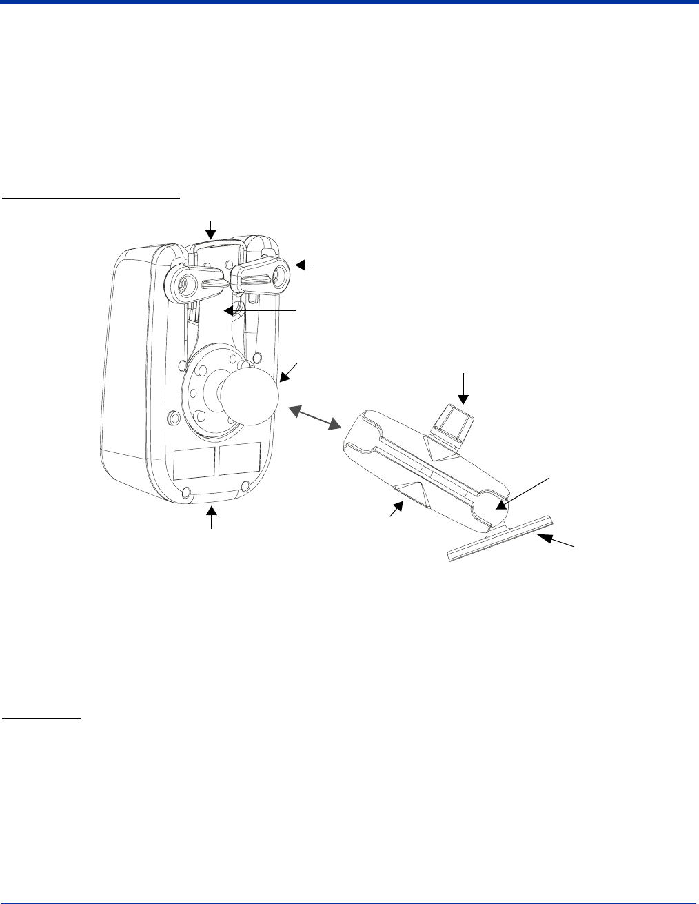
Dolphin® 9500 Series Mobile Computer User’s Guide - Preliminary Rev (d) 12/17/04 13 - 5
Installing the Dolphin Mobile Base
To install the Dolphin Mobile Base, you need to mount it securely to an appropriate location and supply it with power.
Mounting the Mobile Base
The adjustable mounting bracket holds the terminal securely in place and gives the user a variety of options for mounting the
Mobile Base. When selecting a location, keep in mind that the power supply and serial connectors point straight out the bottom
panel.
Back Panel and Brackets
1. Loosen the turnscrew.
2. Insert the ball joint of the mounting bracket to the back of the bracket.
3. Insert the ball joint on the back of the Mobile Base into the other side of the bracket.
4. Tighten the turnscrew to secure both ball joints.
5. Secure the mounting bracket to the appropriate location.
Back Panel
Latch
The latch sits on top of the spring arm assembly and holds the back of the terminal securely in place. The graphic above
displays the mounting of a Dolphin 9500 terminal. There is another Dolphin Mobile Base that contains a special latch to
accommodate the pistol-grip handle on the Dolphin 9550.
Locking Tabs
When positioned as shown in the above graphic, the locking tabs secure the spring arm assembly, latch, and terminal
in place. When seating a terminal, turn both arms up to allow the spring arm to move as necessary while the terminal
is being inserted. After the terminal is seated, turn both arms toward the center to lock them.
Turnscrew
Power supply and RS-232
connectors (not in view) Mounting Bracket
Locking tabs
Ball Joint
Bracket
Latch
Spring Arm Assembly
Ball Joint

13 - 6 Dolphin® 9500 Series Mobile Computer User’s Guide - Preliminary Rev (d) 12/17/04
The both locking tabs must be pointing up to insert or remove a terminal in the Mobile Base.
Spring Arm Assembly
The spring arm assembly is the column that connects the latch to the back of the Mobile Base.
Ball Joints
There are two ball joints: one on the back of the Mobile Base and one on the mounting bracket. Both ball joints are
inserted into the bracket and secured to mount the Mobile Base.
Connectors
The power and RS-232 connectors are located on the bottom panel. For more information, see Bottom Panel on page
13-3.
Brackets
Bracket
The bracket contains the turnscrew and two slots. Ball joints are inserted into each slot and secured with the turnscrew.
Turnscrew
The turnscrew is located on the top of the bracket. Rotate the turnscrew to secure or loosen the ball joint slots.
Mounting Bracket
The mounting bracket is what you attach to the mounting surface. It is comprised of a ball joint and flat disk. The disk
contains drill holes you use to secure the Mobile Base to the mounting surface.
Powering the Dolphin Mobile Base
Note: Hand Held Products recommends that you leave the Mobile Base connected to its power source at all times.
The Mobile Base is powered via the power connector on the bottom panel; see Bottom Panel on page 13-3. Both the power and
serial connectors are straight out, not at an angle. The Mobile Base must be powered by a 12 to 48 volt DC source.

Dolphin® 9500 Series Mobile Computer User’s Guide - Preliminary Rev (d) 12/17/04 13 - 7
Setting the Mobile Base Up for Communications
The Mobile Base RS-232 interface allows the Dolphin terminal to communicate to a personal computer, modem, or any standard
RS-232 device using a standard serial cable and communications software.
Connecting the Cables
Connect the Mobile Base to the host computer or other device by plugging an RS-232 serial cable into the RS-232
Communications Port on the bottom of the Mobile Base. Plug the other end of the RS-232 serial cable into the correct port on
the host RS-232 device.
The wiring of your cable depends on whether the other device is set up as a Data Communications Equipment (DCE) or Data
Terminal Equipment (DTE) device.
The Mobile Base Communication Port is configured as a DCE device. To communicate with a DTE device such as a computer,
use a standard (or straight-through) RS-232 cable. To communicate with a DCE device, use either a null modem adapter in line
with a standard RS-232 cable, or a null-modem serial cable.
RS-232 Pin Configuration
Refer to this table if you want to make your own cables. To do so, you must determine if your host RS-232 device is
• 9-pin or 25-pin and
• configured as a DCE or DTE device.
Mobile Base /Host Port
(DCE) IBM AT DB9
(DTE) IBM XT DB25
(DTE) Modem DB25
(DCE)
Pin / Input Signal
2 / (RD) 2 3 2
3 / (TD) 3 2 3
5 / (SG) 5 7 7
4 / (DTR) 420 6
6 / (DSR) 6 6 20
7 / (RTS) 7 4 5
8 / (CTS) 8 5 4
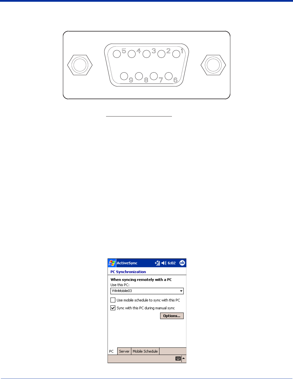
13 - 8 Dolphin® 9500 Series Mobile Computer User’s Guide - Preliminary Rev (d) 12/17/04
Mobile Base Serial Connector
The following diagram displays the pin diagram of the serial connector of the bottom panel of the Mobile Base.
Note: Signals referenced are for a DTE device.
The Mobile Base connector is straight to the printed circuit board (PCB). The ninth pin sends 500mA at 5V power out. This can
power a peripheral device, such as a mobile printer, as long as that peripheral device can accept 500mA at 5V.
Configuring the Terminal for ActiveSync Communications
1. On the terminal, tap Start > ActiveSync > Tools > Options. ActiveSync opens displaying the PC tab.
2. In the Use this PC drop-down list, select the name of the host PC.
Pin # Description
1 Internal Jumper to Pin 6
2 TXD
3 RXD
4 DSR
5 GND
6 DTR
7 CTS
8RTS
9 5 VOLT OUT
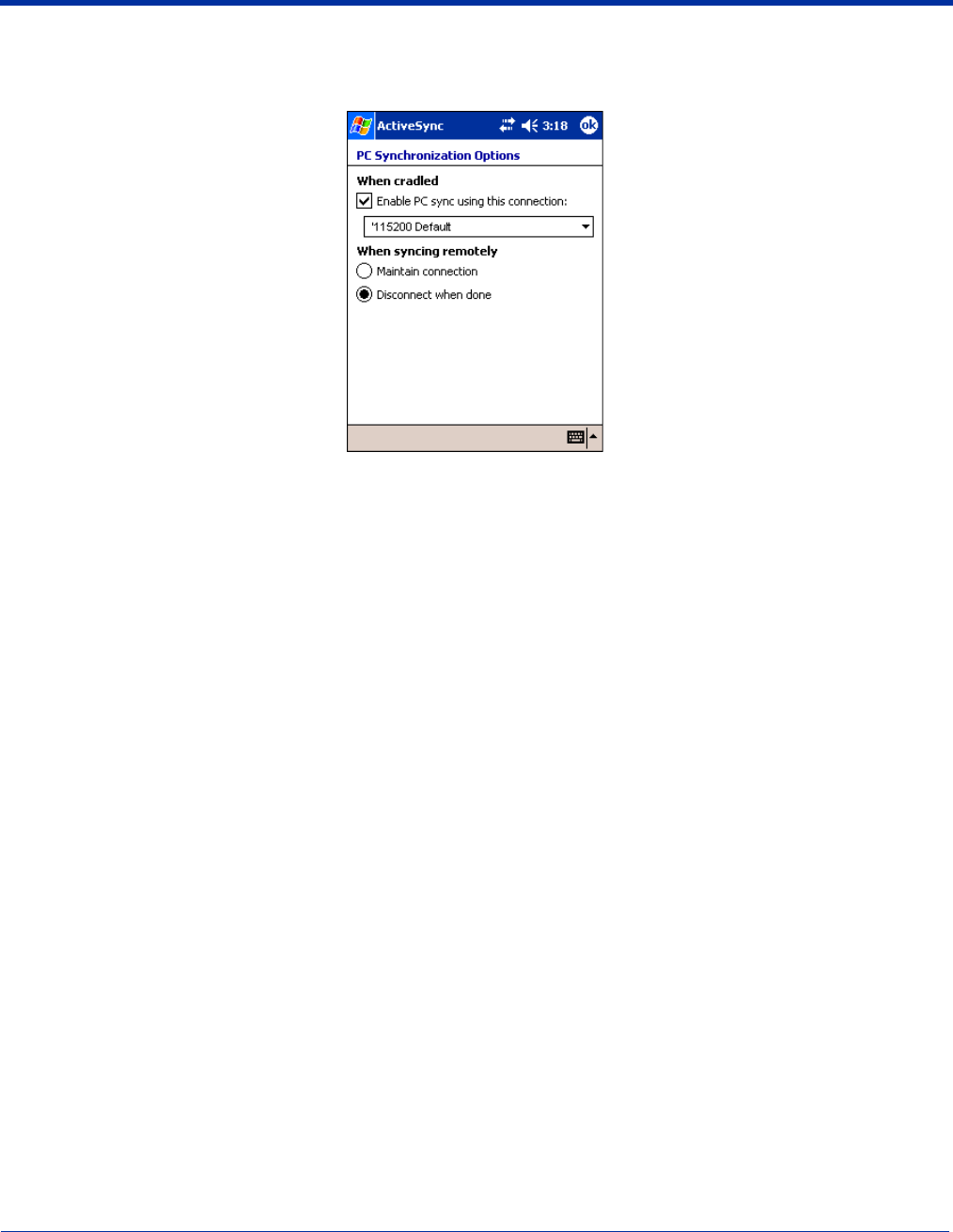
Dolphin® 9500 Series Mobile Computer User’s Guide - Preliminary Rev (d) 12/17/04 13 - 9
3. Select Sync with this PC during manual sync to indicate that the terminal syncs with the selected host PC when
synchronization is run from the terminal.
4. Tap Options.
5. Select Enable PC sync using this connection, then select ‘115200 Default from the drop-down list.
‘115200 baud is recommended for RS-232 communication.
6. Tap OK.
7. Place the Dolphin terminal in the Mobile Base. The Dolphin terminal attempts to start an ActiveSync connection with the
desktop computer automatically.

13 - 10 Dolphin® 9500 Series Mobile Computer User’s Guide - Preliminary Rev (d) 12/17/04

Dolphin® 9500 Series Mobile Computer User’s Guide - Preliminary Rev (d) 12/17/04 14 - 1
14
Dolphin 9500 Series ChargeBase
Overview
The Dolphin ChargeBase is a four-slot charging cradle that can power four Dolphin terminals, and charge their main batteries in
less than four hours.
Charging
The Dolphin ChargeBase completes a full charge of the main battery pack in less than four hours. The ChargeBase also provides
power to the intelligent battery charging system in all Dolphin terminals that senses when a full charge has been achieved and
switches to a trickle charge to maintain the full charge.
As battery packs charge, the charging circuitry follows the two-step charging process (CC-CV) that is recommended for Li-Ion
batteries. The process monitors changes in temperature, current, and voltage.
Convenient Storage
Intelligent battery charging makes the Dolphin ChargeBase a safe and convenient storage receptacle for your Dolphin terminal.
Capacity
The ChargeBase can hold up to four Dolphin 9500 Series terminals. Each charging slot charges each terminal independently of
the other slots.
Use only Dolphin 9500 Series peripherals, power cables, and power adapters. Use of peripherals, cables, or power
adapters not sold/manufactured by Hand Held Products will void the warranty and may damage the terminal.
Use only the Li-ion battery packs provided by Hand Held Products. The use of any battery pack not sold/manufactured
by Hand Held Products in Dolphin 9500 Series terminals will void your warranty and may result in damage to the Dolphin
terminal or battery.
!
!
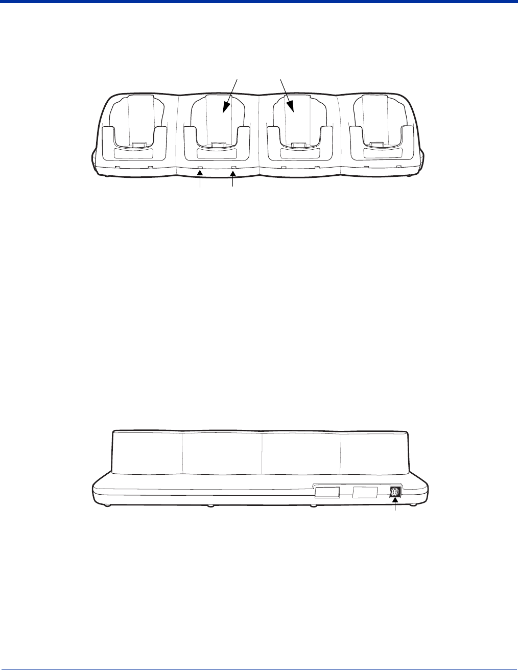
14 - 2 Dolphin® 9500 Series Mobile Computer User’s Guide - Preliminary Rev (d) 12/17/04
Dolphin ChargeBase Parts and Functions
Front Panel
Terminal Wells
The ChargeBase contains four terminals wells. Each well
• Holds and charges the main battery pack of one Dolphin terminal.
• Contains the companion to the industrial-grade, 17-pin connector on the bottom panel of Dolphin terminals.
• Has two LEDs on the front: the Dock LED and the Charge LED.
Dock LED
Each terminal well displays a Dock LED on the front that lights solid green when a terminal is properly seated, which
means that the terminal and the base are connected.
Charge LEDs
Each terminal well displays a Charge LED on the front that lights green to indicate charging. For details, see Charging
Terminals in the ChargeBase on page 14-4.
Back Panel
Power Supply Connector
This connector receives input from the power adapter. Plug the power connector cable from the power adapter into this
connector. There is no ON/OFF switch on the back panel of the ChargeBase. The power switch is on the power adapter.
Charge
LED
Dock
LED
Terminal Wells
Power Supply Connector
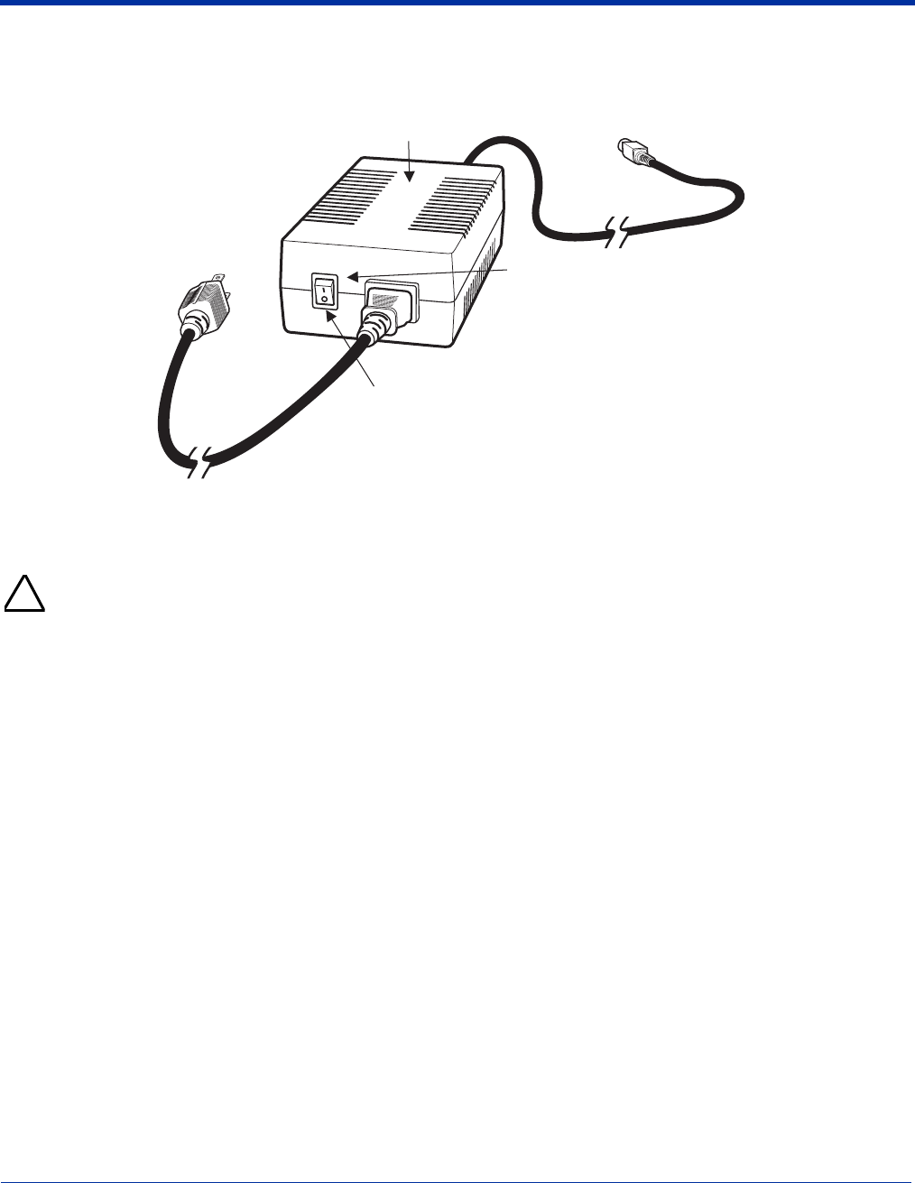
Dolphin® 9500 Series Mobile Computer User’s Guide - Preliminary Rev (d) 12/17/04 14 - 3
Power Supply
The ChargeBase includes a power supply that contains a power adapter to ensure the proper voltage. The power adapter is
plugged into standard AC/DC outlets.
Supplying Power to the ChargeBase
Using a non-Hand Held Products power adapter voids your warranty and could result in serious damage to the circuitry
of the Dolphin ChargeBase.
1. Be sure the power switch on the power adapter is in the OFF position.
2. Plug the power cord into the power adapter.
3. Plug the power connector cable into the power connector on the back panel of the ChargeBase.
4. Plug the power cord into a standard wall outlet.
5. On the power adapter, turn the power switch to the ON position. The LEDs illuminate as the ChargeBase powers up.
6. The ChargeBase is ready to begin charging terminals.
Power Cord
ON/OFF
Switch
ON Position
Power Adapter
Power
Connector
Cable
!
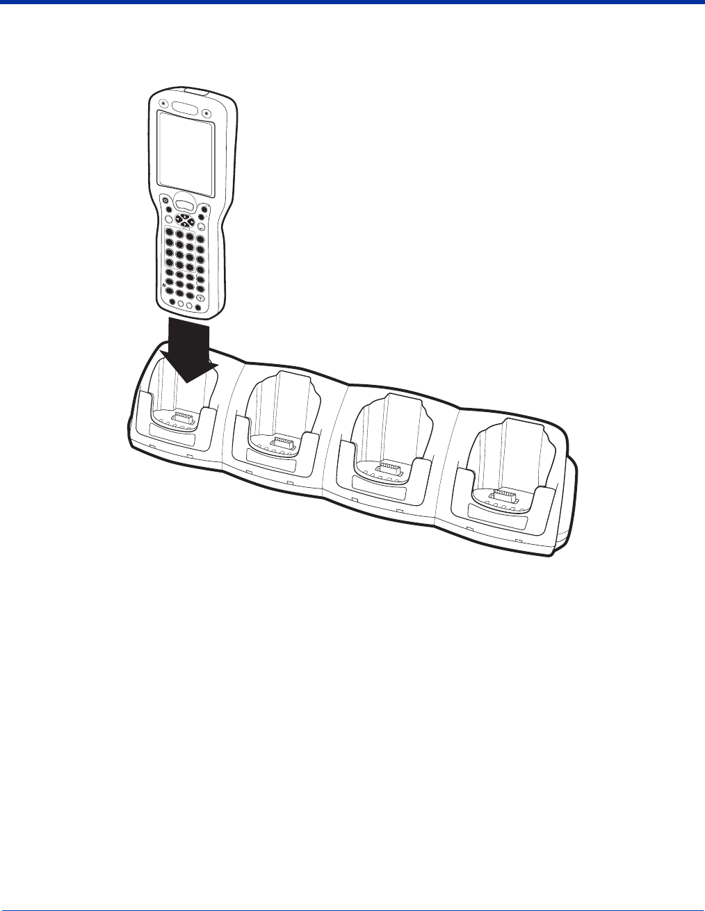
14 - 4 Dolphin® 9500 Series Mobile Computer User’s Guide - Preliminary Rev (d) 12/17/04
Inserting and Removing Terminals
1. To insert the terminal, hold the terminal with the bottom panel perpendicular to the base.
2. Slide the terminal into the well until the Dock LED lights solid green.
3. Charging begins immediately.
Note: To remove a terminal, grasp it firmly in your hand and lift it up and out of the terminal well. The LEDs for the terminal well
turns off.
Charging Terminals in the ChargeBase
The Dolphin ChargeBase charges the main battery of each terminal in less than four hours. The ChargeBase uses the intelligent
battery charging system incorporated into all Dolphin terminals that prevents overcharging. This means that Dolphin terminals
may be stored in the ChargeBase indefinitely without damage to the terminals, battery packs, or the ChargeBase.
1. Power the ChargeBase; see Supplying Power to the ChargeBase on page 14-3.
2. Insert a terminal into a terminal well; see Inserting and Removing Terminals on page 14-4.
3. The Charge LED lights green to indicate that the terminal is powered and charging.
SCAN
ESC
TAB
SFT
ABC
EFG
IJK
MNO
S
RQ
UVW
YZ
D
H
L
P
T
X
NUM
ENT
1 2 3
7 8 9
4 5 6
; :
*
@
F1 F2 F3 F4
F5 F6 F7 F8
START INS BKSP DEL
CTRL ALT
SEND
END
POWER
V
O
L
P
G
V
O
L
P
G
+
+
-0
,
SP
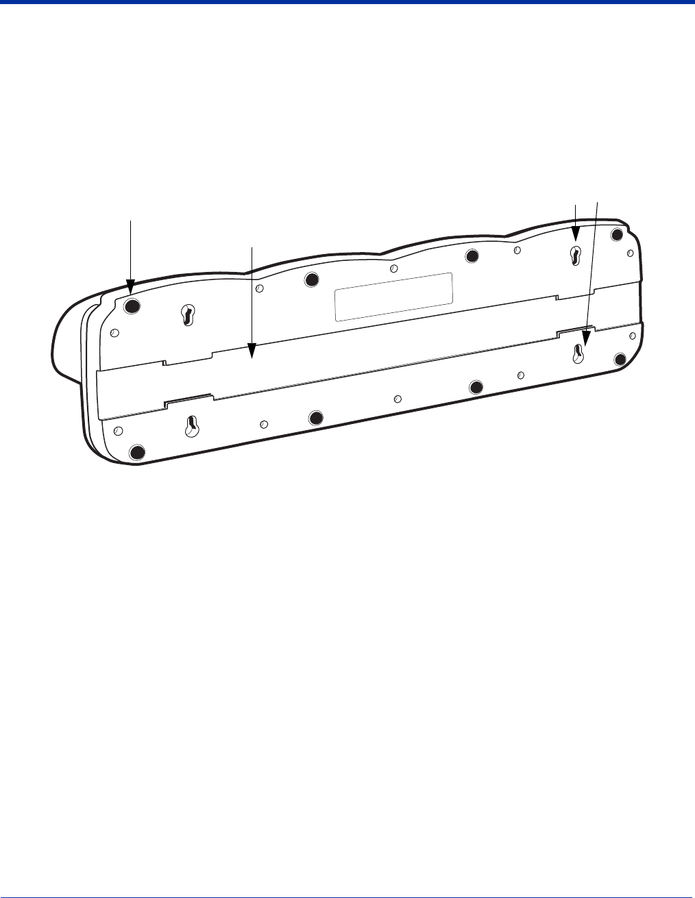
Dolphin® 9500 Series Mobile Computer User’s Guide - Preliminary Rev (d) 12/17/04 14 - 5
Mounting the ChargeBase
The Dolphin ChargeBase should be mounted to a dry, stable surface. When choosing a location, always bear in mind that
• The mounting location must allow users easy access to the power connector.
• The ChargeBase should be oriented so that users can easily read the labels.
Bottom Panel
The bottom panel of the Dolphin 9500 Series ChargeBase offers two mounting options: insert a DIN Rail for desk mounting or
use mounting brackets with the available screw slots for wall mounting.
DIN Rail Slot
Screw Slots
Rubber Feet
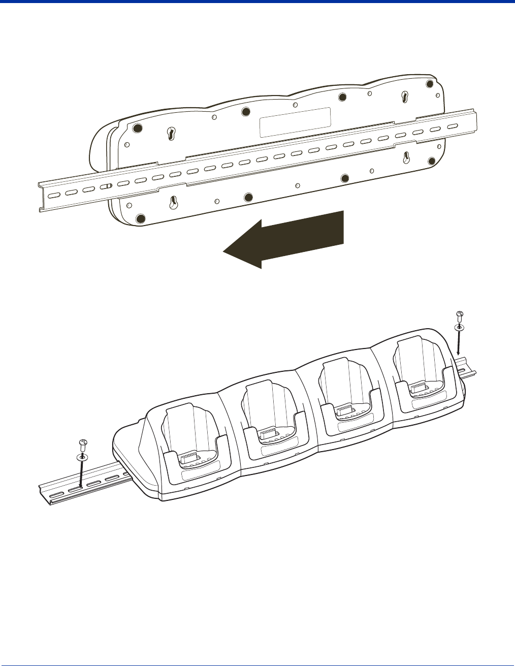
14 - 6 Dolphin® 9500 Series Mobile Computer User’s Guide - Preliminary Rev (d) 12/17/04
Using the DIN Rail
All Dolphin charging/communication cradles have a DIN rail (7.5 X 35 mm) slot on the bottom panel to enable secure mounting.
1. Slide the DIN Rail into the DIN Rail slot on the bottom panel.
2. Turn the ChargeBase and DIN Rail right side up.
3. Secure the DIN Rail to a stable, flat horizontal surface.
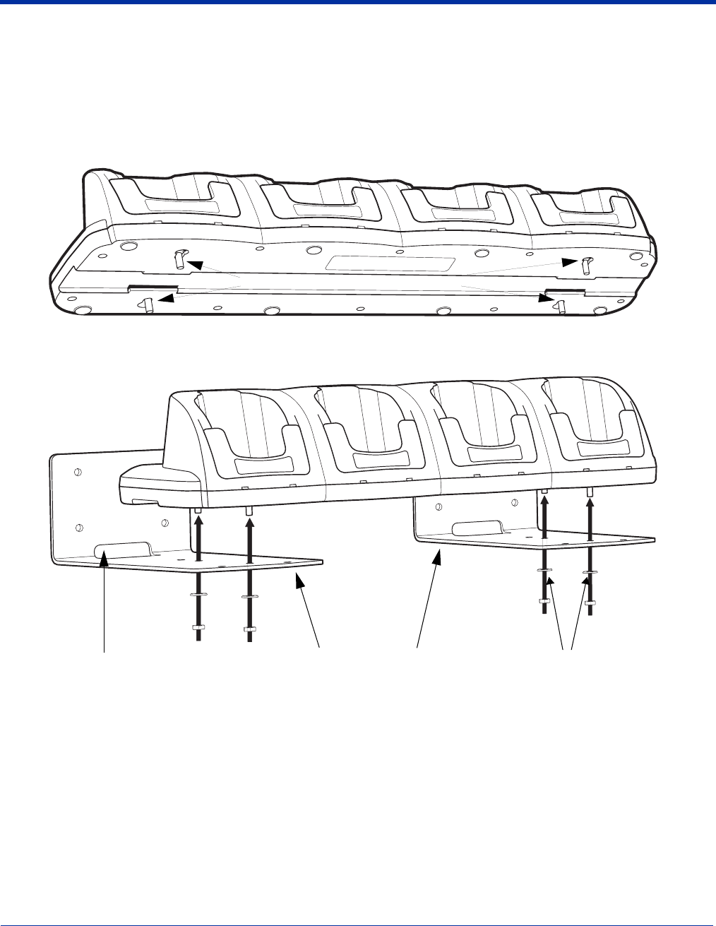
Dolphin® 9500 Series Mobile Computer User’s Guide - Preliminary Rev (d) 12/17/04 14 - 7
Using the Wall Mount Kit
Wall mount kits can be purchased separately to secure the ChargeBase to a wall or other vertical surface. For the ChargeBase,
you need to purchase two kits so that you have two mounting brackets, one for each end of the ChargeBase. Each mounting
bracket contains an open slot in the back to accommodate the connector cables.
Each mounting bracket contains an open slot in the back to accommodate the connector cables.
1. Insert the head of each screw into the round end of each of the four screw slots on the bottom panel. Slide each screw
towards the narrow end of the screw slot.
4. Use a washer/nut set on each screw to secure the screw in each slot.
5. Attach the bottom panel to the two mounting brackets.
Screws in the narrow end of each slot
Washer/Nut
Open Slot for Connector Cables Mounting Brackets
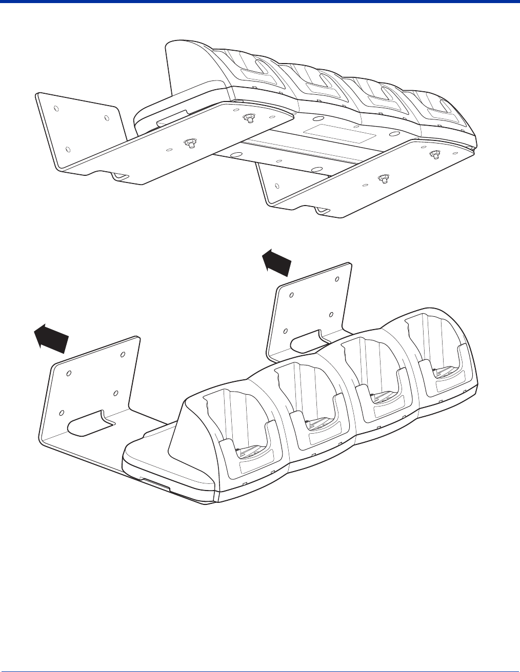
14 - 8 Dolphin® 9500 Series Mobile Computer User’s Guide - Preliminary Rev (d) 12/17/04
6. Using the remaining washer and nut sets, secure the mounting brackets to the bottom panel.
7. Secure the mounting brackets to an appropriate vertical surface.
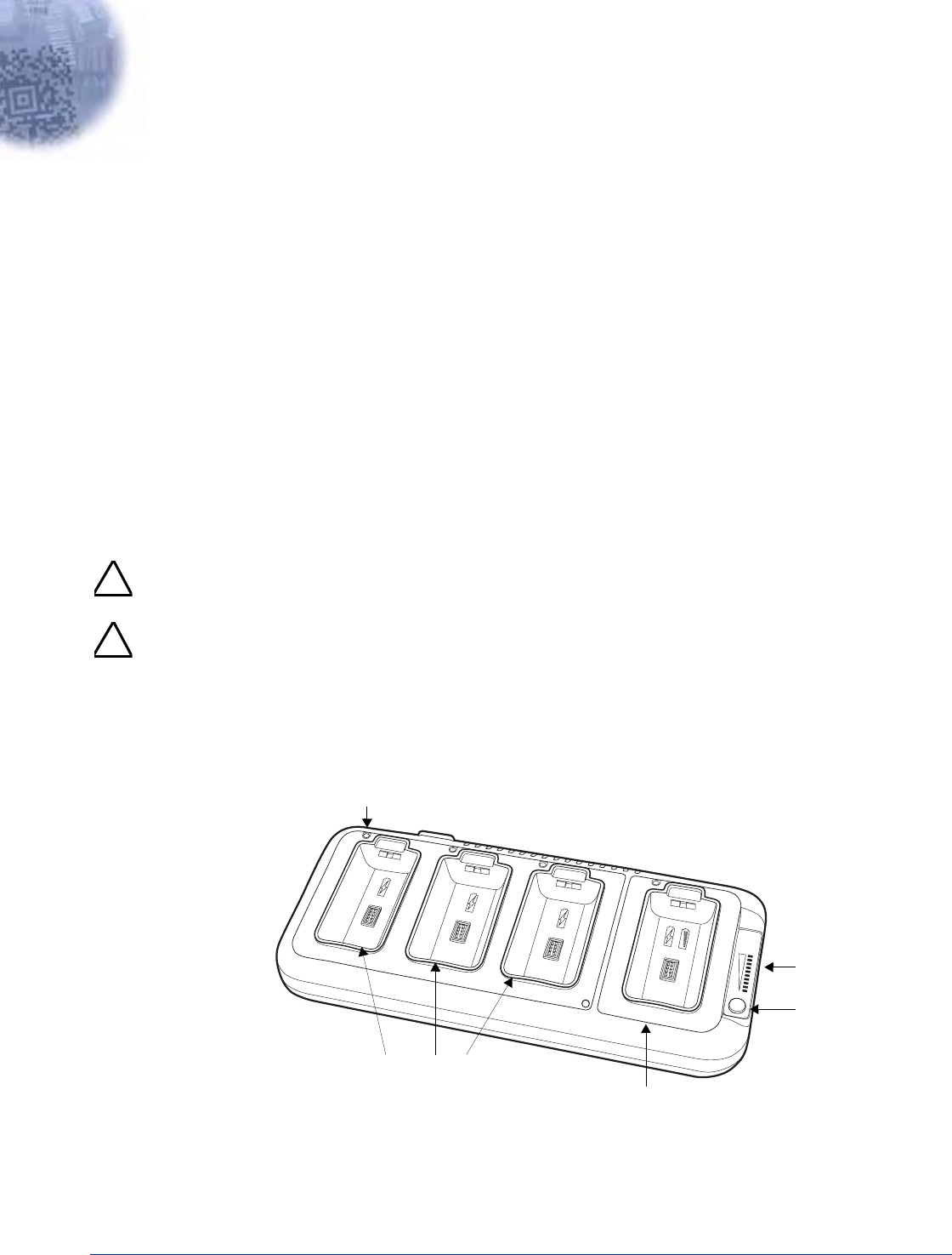
Dolphin® 9500 Series Mobile Computer User’s Guide - Preliminary Rev (d) 12/17/04 15 - 1
15
Dolphin 9500 Series QuadCharger
Overview
The Dolphin QuadCharger is a four-slot charging station that provides intelligent battery management for the Li-ion battery packs
used in Dolphin 9500 Series terminals. Batteries charge in less than four hours. The fourth slot features a battery analyzer that
completely resets a battery, then displays its remaining capacity.
Compatibility
The QuadCharger is compatible with the Li-ion batteries that power the Dolphin 9500 Series of mobile computing devices.
Charging Process
Each charging slot works independently of the other three. As battery packs charge, the charging circuitry follows the two-step
charging process (CC-CV) that is recommended for Li-Ion batteries. The process monitors changes in temperature, current, and
voltage and resets the battery pack.
Capacity
The Dolphin QuadCharger holds four Li-ion batteries.
Use only Dolphin 9500 Series peripherals, power cables, and power adapters. Use of peripherals, cables, or power
adapters not sold/manufactured by Hand Held Products will void the warranty and may damage the terminal.
Use only the Li-ion battery packs provided by Hand Held Products. The use of any battery pack not sold/manufactured
by Hand Held Products in Dolphin 9500 Series terminals will void your warranty and may result in damage to the Dolphin
terminal or battery.
Dolphin QuadCharger Parts and Functions
Top Panel
Charging Slots
The QuadCharger contains four charging slots. Each slot holds one Li-ion battery and charges it independently of the
other slots. When a battery is placed in each slot, it immediately begins charging.
!
!
O
SLOT 4
BATTERY
CAPACITY
100%
0%
ANALYZE
CHARGE/ANALYZE
1
2
3
4
Charging Slots
Status LED
Charge/Analyze Slot
Battery
Capacity
LEDs
Analyze
Button
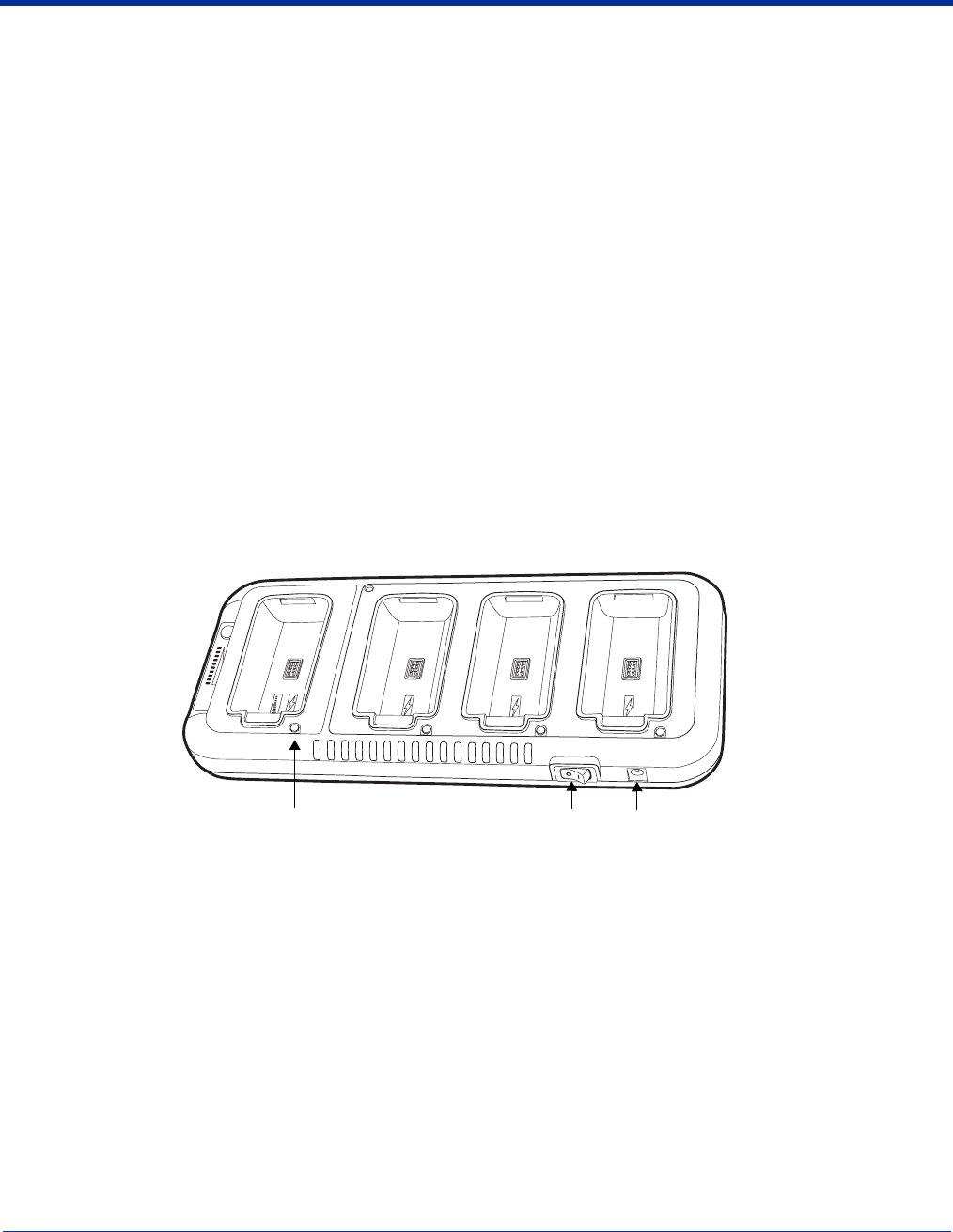
15 - 2 Dolphin® 9500 Series Mobile Computer User’s Guide - Preliminary Rev (d) 12/17/04
Charge/Analyze Slot
This is the fourth slot and the only one that can be used to analyze a battery. When a battery is placed in this slot, it
begins charging just as it does in the other three slots. However, if you press the ANALYZE button, it runs the battery
in this slot through the complete Analyze cycle. For more information, see Using the Battery Analyzer on page 15-4.
Battery Capacity Indicator LEDs
These LEDs give a readout of the remaining battery capacity after it has run through a complete analyze cycle. For more
information, see Battery Capacity Indicator LEDs on page 15-2.
Analyze Button
Press this button to start a battery analyze cycle. For more information, see Using the Battery Analyzer on page 15-4.
Status LEDs
A status LED is located above each of the four battery slots. The color of the LED indicates the charge status of the
batteries in its slot.
Back Panel
Power Switch
Toggle the power switch to turn the QuadCharger on and off.
Power Supply Connector
Use this connector to attach the power supply to the QuadCharger. The universal power supply accepts input voltages
between 90-265 volts.
Status LED color This color indicates that the battery in the slot…
Green Has completed its charge cycle and is ready for use.
Orange Is being charged at a maximum charge rate.
Red Encountered an error during the most recent charge cycle.
1
2
3
4
Swc
O
CHARGE/ANALYZE
0%
ALYZE
LOT 4
TTERY
PACITY
0%
Power Supply Connector
Power Switch
Status LED
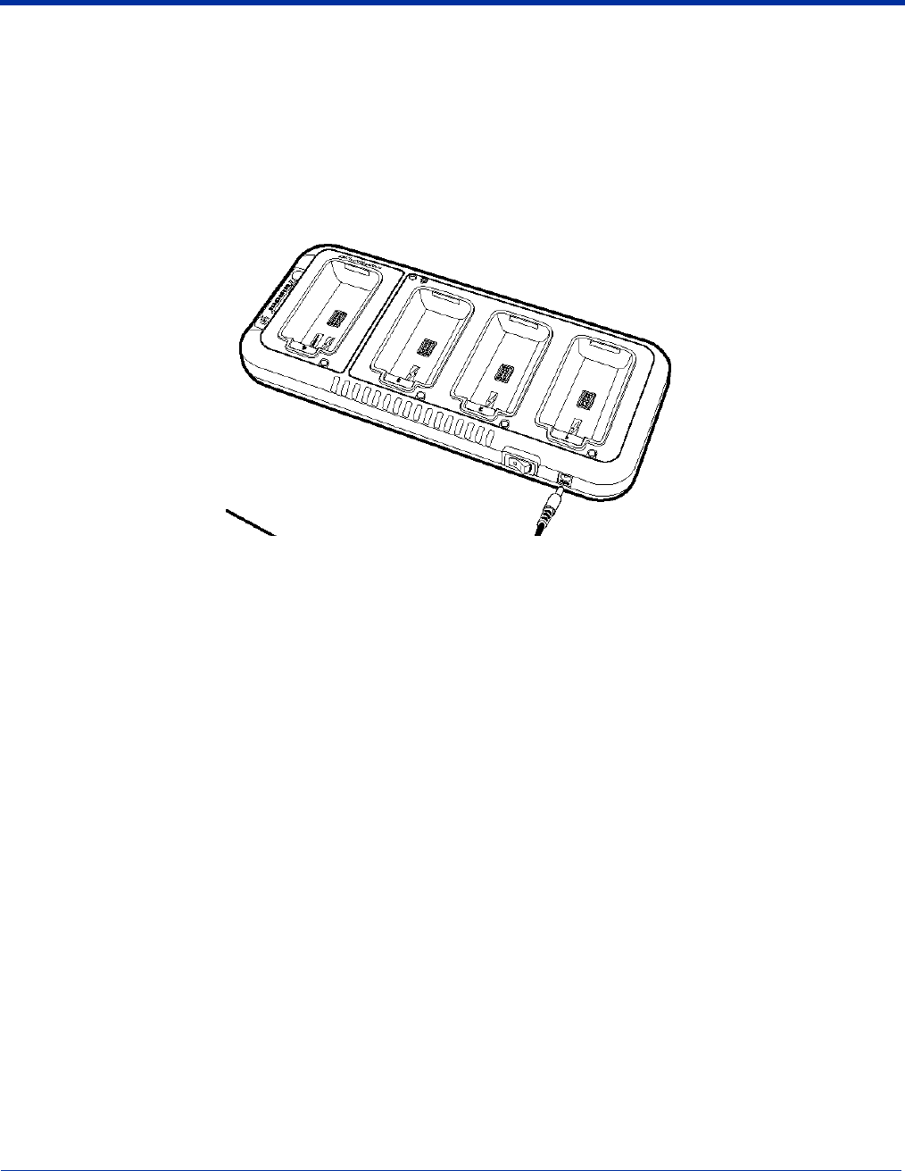
Dolphin® 9500 Series Mobile Computer User’s Guide - Preliminary Rev (d) 12/17/04 15 - 3
Supplying Power to the QuadCharger
The QuadCharger must be connected to a power source via the Hand Held Products power adapter cable so that voltage is
adjusted appropriately.
1. Locate the AC power adapter cable and plug it into the power source.
2. Connect the power cable to the power adapter.
3. Connect the power cable to the supply connector on the back of the QuadCharger.
4. Press the power switch to the ON position.
The power LED illuminates green, and the charger performs a self-diagnostic test that lasts approximately five seconds.
Inserting and Removing Battery Packs
To insert a battery pack, place the end of the battery without the locking tab into the bottom of the charging pocket and snap the
battery into place with a hinging motion. The Status LED for that particular slot illuminates orange when the battery has been
properly inserted.
To remove a battery pack, push the locking tab down and pull the battery out from the charging slot with a hinging motion.
Storing Batteries
Recommendations
To maintain top performance from batteries, follow these storage guidelines:
• Avoid storing batteries outside of the specified temperature range of -4 to 104° F (-20 to 40°C) or in extremely high humidity.
• For prolonged storage, do not keep batteries stored in a charger that is connected to a power source.
Charging Batteries in the QuadCharger
For best results, battery packs should be at room temperature before recharging them; temperature has a marked effect on
charging. The recommended temperature range is 50° to 95° F (10° to 35° C).
1. Set up the QuadCharger.
2. Supply the QuadCharger with power and turn the power switch on.
3. Insert batteries into the appropriate slots.
The Status LED for each slot turns orange to indicate that the battery has begun a charge cycle.
4. When the Status LED turns green, the battery in the slot has completed charging.

15 - 4 Dolphin® 9500 Series Mobile Computer User’s Guide - Preliminary Rev (d) 12/17/04
Using the Battery Analyzer
Location
The battery analyzer is located in the fourth slot - named the Charge/Analyze slot - of the ChargeBase. Only a battery placed in
this slot can be run through an Analyze cycle. This slot contains Battery Capacity LEDs along the right side.
Purpose
Using the Charge/Analyze slot helps you monitor the charge capacity of Li-ion batteries over time.
Analyze Cycle
The Analyze cycle is initiated when a battery is placed in the Charge/Analyze slot and the ANALYZE button is
pressed. In an Analyze cycle, batteries are completely discharged, then recharged to capacity. The length of time
it takes for a battery to complete the Analyze cycle varies depending on the initial state of the battery’s charge.
Minimum time is 8 hours, maximum time is 12 hours.
Battery Capacity LEDs
The Battery Capacity LEDs are located along the right side of the Charge/Analyze slot. Each LED equates to
10% battery capacity. These LEDs display the capacity of the battery at the end of the Analyze cycle. Battery
capacity is displayed as a percentage of measured capacity/rated capacity.
Status LED
The Charge/Analyze slot also contains a standard status LED in the upper, left corner of the slot. When this slot
is used for regular charging, this LED operates in the usual manner; see Status LEDs on page 15-2.
When this slot is being used to analyze a battery, the Status LED functions as follows:
To Analyze a Battery
1. Insert the battery into the Charge/Analyze slot (the fourth).
2. Press the ANALYZE button. The Status LED flashes orange to indicate that the analyzing cycle has begun.
The Dolphin QuadCharger is accumulating battery pack information during the entire Analyze cycle. Do NOT remove the
battery until the cycle has been completed.
3. Upon completion of the Analyze cycle, the Status LED lights solid green, and the Battery Capacity Indicator LEDs display the
battery’s capacity.
You can verify a battery’s capacity by installing the battery in a terminal and checking the power; see Power on page 5-10 for
details.
Status LED color Indicates that the battery in the slot…
Solid Green Has completed the Analyze cycle.
Flashing Orange Is being analyzed.
Solid Red Encountered an error during the Analyze cycle.
!

Dolphin® 9500 Series Mobile Computer User’s Guide - Preliminary Rev (d) 12/17/04 15 - 5
Mounting the QuadCharger
The Dolphin QuadCharger should be on a dry, stable surface. To easily adapt the QuadCharger to your environment, it can be
mounted on a flat, horizontal surface such as a desktop or workbench, or a flat, vertical surface such as a wall.
When choosing a location, always bear in mind that
• the mounting location must allow users easy access to power switch and power connector.
• the QuadCharger should be oriented so that users can easily insert and remove battery packs and read the labels, especially
for the Battery Analyzer.
Desk Mounting
All Dolphin charging/communication cradles have a DIN rail (7.5 X 35 mm) slot on the bottom panel to enable secure mounting.
To mount the QuadCharger, you slide the DIN rail slot along the bottom panel and secure it. Then, using the appropriate nuts
and bolts, secure the DIN rail to the desk or wall.
The following graphic displays how to mount the QuadCharger to a desk:
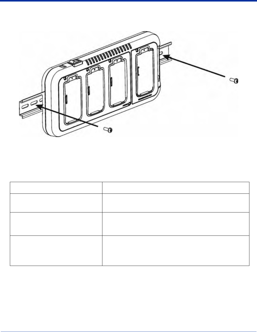
15 - 6 Dolphin® 9500 Series Mobile Computer User’s Guide - Preliminary Rev (d) 12/17/04
Wall Mounting
The following graphic displays how mount a QuadCharger to a wall:
Troubleshooting
If you encounter problems with your Dolphin QuadCharger, refer to chart below for possible solutions. If problems persist, please
contact Hand Held Products Technical Support.
Problem Issue
The Status LED does not come on when I
insert a battery pack into the Dolphin
QuadCharger
Check the power connections on the Dolphin QuadCharger; make sure
the POWER switch is ON and the battery pack is properly seated.
The Status LED lights red during charging. Try to charge the battery in one of the other charging slots. If the red
Status LED comes on again, then the problem is associated with the
battery pack. If the red status stays with the charging slot, the problem is
associated with the charging circuity.
The Status LED lights red and stays on
without a battery in the charging slot. An error occurred during the self-diagnostic test for that particular
charging pocket. Call Hand Held Products Product Service and request
an RMA.
For additional warranty and return information, see Service, Support,
and Warranty on page 16-1.

Dolphin® 9500 Series Mobile Computer User’s Guide - Preliminary Rev (d) 12/17/04 16 - 1
16
Service, Support, and Warranty
Return Information
Should your unit or any of the peripherals prove to be defective within the stated warranty period from the date of purchase, return
the product, as described in the Repair Maintenance Authorization (RMA) procedures below, and we will, at our option, repair or
replace the product, to whatever extent Hand Held Products deems necessary to restore the product to proper operating
condition, without any charge to you.
You must obtain an RMA number to receive service from any of Hand Held Products’ repair facilities. Failure to obtain an RMA
number before shipping your product to this repair facility can delay the processing of your repair request. Please contact the
Product Service facility (numbers listed below) nearest you to receive an RMA number.
If you purchased the product from an Authorized Hand Held Products Reseller, contact the Reseller with the unit's serial number.
Your Reseller will contact Hand Held Products, on your behalf, to arrange for the unit to be serviced.
Calling for an RMA Number
If you purchased the product directly from Hand Held Products, or have been instructed by your Reseller to contact Hand Held
Products directly, call the Product Service Department in your area to request an RMA number. You can also access product
service and repair online at: www.handheld.com.
Requirements
When calling for service at any of our repair facilities, please be prepared to give the following information:
• Product type and serial number
• Brief description of problem
• Dated proof-of-purchase
If your equipment is still covered under the initial end-user's product warranty, please notify the Product Services Representative
when you call.
Service and Repair Locations.
Shipping
Please make note of the RMA number (if required) and the product's serial number before shipping. If you must return your unit,
place the product in its original packaging with a copy of your original invoice (this helps avoid possible service delays) and ship
the product prepaid to the appropriate address below. For your protection, we recommend you insure any equipment being sent
to Hand Held Products.
Write the RMA number on the mailing label under the address!
Repair
After repair or replacement of the equipment, Hand Held Products will ship the product, at our cost, to your location. Non-warranty
repairs will be returned, at the customer's expense, unless otherwise requested. Units currently under a service agreement will
be shipped per the service agreement.
North America/Canada
Hand Held Products Corporate Offices
Telephone: (800) 782-4263, option 3
Fax: (704) 566-6015
E-mail: ProductService@handheld.com
Latin America
Hand Held Products Latin America
Telephone: +1 239-263-7600
Fax: +1 239-263-9689
E-mail: LASupport@handheld.com
Asia Pacific
Hand Held Products Asia/Pacific
Telephone: +852-2511-3050
Fax: +852-2511-3557
E-mail: Asiasupport@handheld.com
Europe, Middle East, and Africa
(EMEA)
Hand Held Products Europe
Telephone:+ 31 (0) 40 29 01 633
Fax: + 31 (0) 40 2901631
E-mail: EuroService@handheld.com
Brazil
Hand Held Products Brazil
Telephone: +55 (21) 2176-0250
Fax: +55 (21) 2494-5033
E-mail: suporte@handheld.com
Japan
Hand Held Products Japan
Telephone: +81-3-5770-6312
Fax: +81-3-5770-6213
E-mail: KobayashiT@handheld.com

16 - 2 Dolphin® 9500 Series Mobile Computer User’s Guide - Preliminary Rev (d) 12/17/04
Technical Assistance
If you have a question or problem with your unit, you can obtain technical assistance from Hand Held Products’ Technical
Support.
North America/Canada:
Telephone: (800) 782-4263, Option 4 (8 a.m. to 6 p.m. EST)
Fax number: (315) 685-4960
E-mail: support@handheld.com
Europe, Middle East, and Africa:
Telephone
European Ofc: +31 (0) 40 29 01 600
U.K. Ofc: +44 1925 240055
E-mail: euro_support@handheld.com
Asia:
Telephone: +81-3-5770-6312
E-mail: asia_support@handheld.com
Latin America:
Telephone: (239) 263-7600
E-mail: la_support@handheld.com
Assistance Online
You can also access technical assistance online at: www.handheld.com.

16 - 3 Dolphin® 9500 Series Mobile Computer User’s Guide - Preliminary Rev (d) 12/17/04
Limited Warranty
Hand Held Products, Inc. (“Hand Held Products”) warrants its products to be free from defects in materials and workmanship and
to conform to Hand Held Products’s published specifications applicable to the products purchased at the time of shipment. This
warranty does not cover any Hand Held Products product which is (i) improperly installed or used; (ii) damaged by accident or
negligence, including failure to follow the proper maintenance, service, and cleaning schedule; or (iii) damaged as a result of (A)
modification or alteration by the purchaser or other party, (B) excessive voltage or current supplied to or drawn from the interface
connections, (C) static electricity or electro-static discharge, (D) operation under conditions beyond the specified operating
parameters, or (E) repair or service of the product by anyone other than Hand Held Products or its authorized representatives.
This warranty shall extend from the time of shipment for the duration published by Hand Held Products for the product at the time
of purchase (“Warranty Period”). Any defective product must be returned (at purchaser’s expense) during the Warranty Period
to Hand Held Products’ factory or authorized service center for inspection. No product will be accepted by Hand Held Products
without a Return Materials Authorization, which may be obtained by contacting Hand Held Products. In the event that the product
is returned to Hand Held Products or its authorized service center within the Warranty Period and Hand Held Products determines
to its satisfaction that the product is defective due to defects in materials or workmanship, Hand Held Products, at its sole option,
will either repair or replace the product without charge, except for return shipping to Hand Held Products.
EXCEPT AS MAY BE OTHERWISE PROVIDED BY APPLICABLE LAW, THE FOREGOING WARRANTY IS IN LIEU OF ALL
OTHER COVENANTS OR WARRANTIES, EITHER EXPRESSED OR IMPLIED, ORAL OR WRITTEN, INCLUDING, WITHOUT
LIMITATION, ANY IMPLIED WARRANTIES OF MERCHANTABILITY OR FITNESS FOR A PARTICULAR PURPOSE.
HAND HELD PRODUCTS’ RESPONSIBILITY AND PURCHASER’S EXCLUSIVE REMEDY UNDER THIS WARRANTY IS
LIMITED TO THE REPAIR OR REPLACEMENT OF THE DEFECTIVE PRODUCT. IN NO EVENT SHALL HAND HELD
PRODUCTS BE LIABLE FOR INDIRECT, INCIDENTAL, OR CONSEQUENTIAL DAMAGES, AND, IN NO EVENT, SHALL ANY
LIABILITY OF HAND HELD PRODUCTS ARISING IN CONNECTION WITH ANY PRODUCT SOLD HEREUNDER (WHETHER
SUCH LIABILITY ARISES FROM A CLAIM BASED ON CONTRACT, WARRANTY, TORT, OR OTHERWISE) EXCEED THE
ACTUAL AMOUNT PAID TO HAND HELD PRODUCTS FOR THE PRODUCT. THESE LIMITATIONS ON LIABILITY SHALL
REMAIN IN FULL FORCE AND EFFECT EVEN WHEN HAND HELD PRODUCTS MAY HAVE BEEN ADVISED OF THE
POSSIBILITY OF SUCH INJURIES, LOSSES, OR DAMAGES. SOME STATES, PROVINCES, OR COUNTRIES DO NOT
ALLOW THE EXCLUSION OR LIMITATIONS OF INCIDENTAL OR CONSEQUENTIAL DAMAGES, SO THE ABOVE
LIMITATION OR EXCLUSION MAY NOT APPLY TO YOU.
All provisions of this Limited Warranty are separate and severable, which means that if any provision is held invalid and
unenforceable, such determination shall not affect the validity of enforceability of the other provisions hereof.
The limited duration of the warranty for Dolphin 9500 Series is as follows:
• Dolphin 9500 and Dolphin 9550 terminals with an integrated imager are covered by a two-year limited warranty.
• Dolphin 9501 and Dolphin 9551 terminals with an integrated laser engine are covered by a one-year limited warranty.
• Touch screens are covered by a one-year limited warranty.
• The limited duration of the warranty for the Dolphin HomeBase, Mobile Base, Mobile Charger, and QuadCharger is one year.
• The limited duration of the warranty for batteries is one year. Use of any battery not sold/manufactured by Hand Held Products
may damage the terminal and/or the battery and will void the warranty. Batteries returned to Hand Held Products in a reduced
state may or may not be replaced under this warranty. Battery life will be greatly increased when following the battery
instructions in this user’s guide.
• Use of any peripheral with the Dolphin terminal not manufactured/sold by Hand Held Products will void the warranty. This
includes but is not limited to: cables, power supplies, cradles, and docking stations.
• Use only power adapters approved for use by Hand Held Products. Failure to do so may result in improper operation or
damage to the unit and will void the warranty.
Hand Held Products, Inc. extends these warranties only to the first end-users of the products. These warranties are non-
transferable.
How to Extend Your Warranty
Hand Held Products offers a variety of service plans on our hardware products. These agreements offer continued coverage for
your equipment after the initial warranty expires. For more information, contact your Hand Held Products Sales Representative,
Customer Account Representative, the Product Service Marketing Manager, or your Authorized Reseller.

16 - 4 Dolphin® 9500 Series Mobile Computer User’s Guide - Preliminary Rev (d) 12/17/04

Dolphin® 9500 Series Mobile Computer User’s Guide - Preliminary Rev (d) 12/17/04 A - 1
Appendix A - Keyboard Combinations
General Windows Keyboard Shortcuts
Use the keyboard shortcuts in the chart below to navigate the Dolphin 9500 and Dolphin 9550 terminal keyboards. These are
standard keyboard shortcuts for Windows applications.
Press these keys, To…
CTRL + C Copy
CTRL + X Cut
CTRL + V Paste
CTRL + Z Undo
DELETE Delete
CTRL + RIGHT ARROW Move the insertion point to the beginning of the next word.
CTRL + LEFT ARROW Move the insertion point to the beginning of the previous word.
CTRL + DOWN ARROW Move the insertion point to the beginning of the next paragraph.
CTRL + UP ARROW Move the insertion point to the beginning of the previous paragraph.
SHIFT with any of the arrow keys Select more than one item in a window or on the desktop, or select text
within a document.
CTRL+ A Select all.
ALT + ENTER View properties for the selected item.
ALT + TAB Switch between open items.
ALT + ESC Cycle through items in the order they were opened.
ALT + Tap on Touch screen Right-click
CTRL + ESC Display the Start menu.
ALT + Underlined letter in a menu name Display the corresponding menu.
Underlined letter in a command name on an open
menu Carry out the corresponding command.
BACKSPACE View the folder one level up in My Computer or Windows Explorer.
ESC Cancel the current task.
A
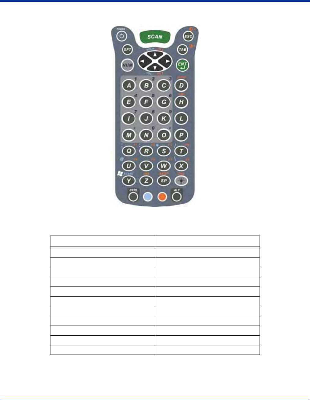
Dolphin® 9500 Series Mobile Computer User’s Guide - Preliminary Rev (d) 12/17/04 A - 2
43-Key Alpha/Numeric Keyboard
Blue Key Combinations
Key Combination Function/Special Character
Blue key + D -
Blue key + H _
Blue key + L =
Blue key + P +
Blue key + Q ;
Blue key + R :
Blue key + S *
Blue key + T /
Blue key + U @
Blue key + X \
Blue key + Y START
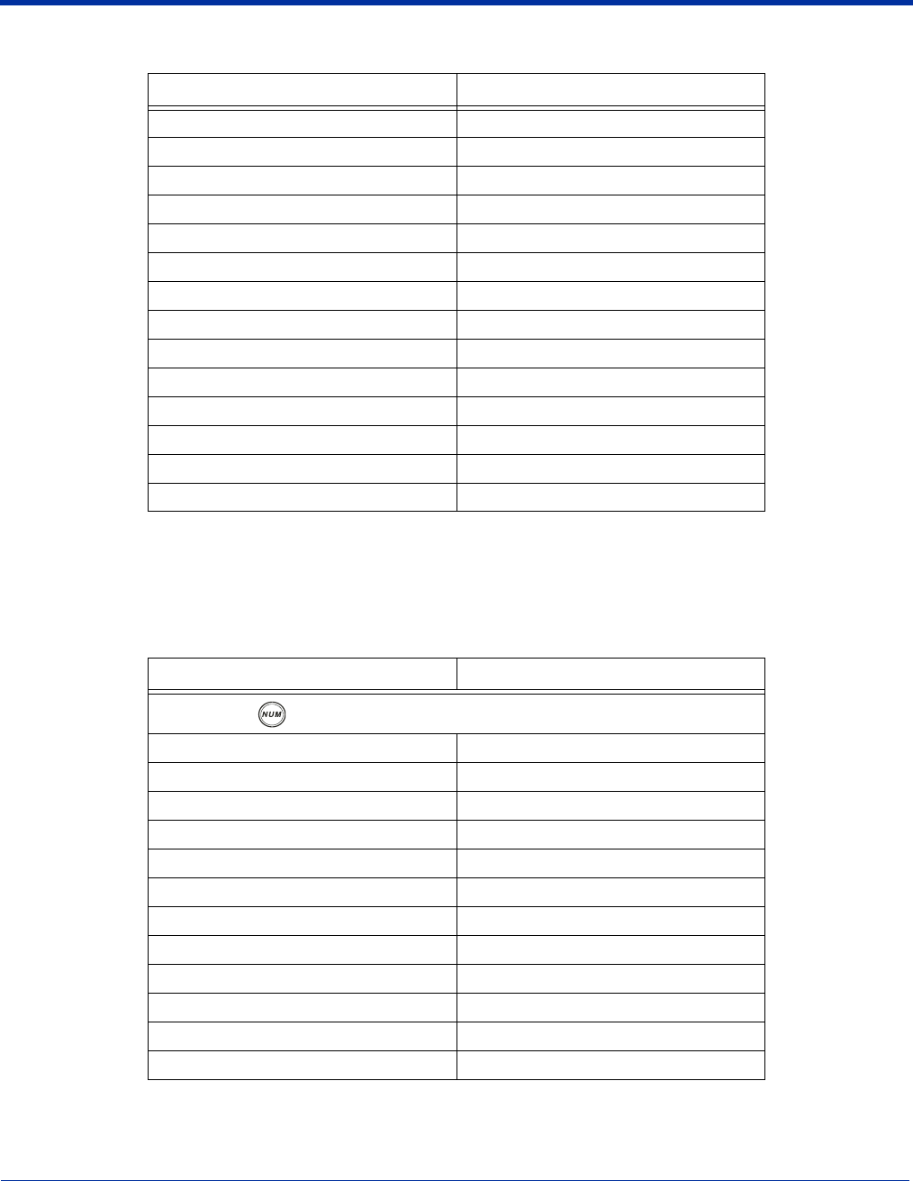
Dolphin® 9500 Series Mobile Computer User’s Guide - Preliminary Rev (d) 12/17/04 A - 3
Red Key Combinations
* Exit the mouse utility prior to adjusting the contrast.
Num Lock Key Combinations
The 43-key keyboard defaults to alpha mode. To switch to num lock mode, press the NUM key once. In Num Lock mode, when
you press a letter key, you type the number indicated by the num lock indicators over the key.
Key Combination Function/Special Character
Red key + ESC Lightens Contrast*
Red key + TAB Darkens Contrast*
Red key + SFT Toggles on Caps Lock
Red key + Q F1
Red key + R F2
Red key + S F3
Red key + T F4
Red key + U F5
Red key + V F6
Red key + W F7
Red key + X F8
Red key + Z Insert
Red key + SP Backspace
Red key + BKSP Delete
Key/Key Combination Function/Special Character
Press the NUM key only once to switch to num lock mode.
NUM + SFT + A !
NUM + SFT + B @
NUM + SFT + C #
NUM + SFT + E $
NUM + SFT + F %
NUM + SFT + G ^
NUM + SFT + I &
NUM + SFT + J *
NUM + SFT + K (
NUM + SFT + M >
NUM + SFT + N )
NUM + SFT + O <
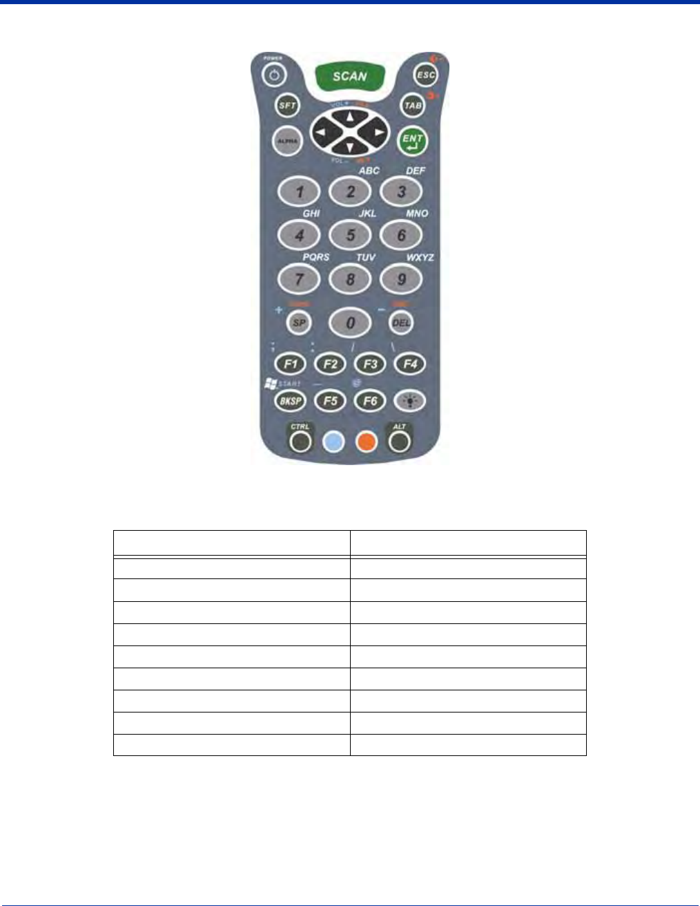
A - 4 Dolphin® 9500 Series Mobile Computer User’s Guide - Preliminary Rev (d) 12/17/04
35-Key Numeric/Alpha Keyboard
Blue Key Combinations
Key Combination Function/Special Character
Blue key + SP +
Blue key + DEL -
Blue key + F1 ;
Blue key + F2 :
Blue key + F3 /
Blue key + F4 \
Blue key + BKSP START
Blue key + F5 _
Blue key + F6 @
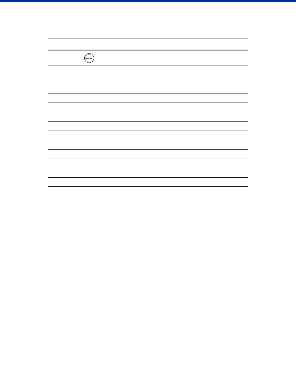
Dolphin® 9500 Series Mobile Computer User’s Guide - Preliminary Rev (d) 12/17/04 A - 5
Alpha Mode Key Combinations
The 35-key keyboard defaults to numeric mode. To switch to alpha mode, press the ALPHA key once. In alpha mode, when you
press a number key, you type the letter indicated by the alpha lock indicators over the key.
Note Please note that when typing in alpha mode, you must use the same multi-press method you would use when typing
letters on a phone keypad. Each key press will type the next letter in the sequence as displayed by the alpha lock indicators over
the number keys.
Key/Key Combination Function/Special Character
Press the ALPA key only once to switch to alpha mode.
ALPHA + 1
When you press 1 repeatedly, the 1 key
produces the following characters in the
following sequence:
. , ‘ ? ! -
ALPHA + SFT + 1 ! < >
ALPHA + SFT + 2 @
ALPHA + SFT + 3 #
ALPHA + SFT + 4 $
ALPHA + SFT + 5 %
ALPHA + SFT + 6 ^
ALPHA + SFT + 7 &
ALPHA + SFT + 8 *
ALPHA + SFT + 9 (
ALPHA + SFT + 0 )
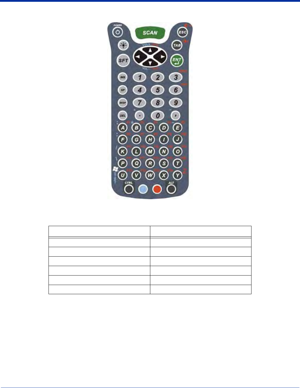
A - 6 Dolphin® 9500 Series Mobile Computer User’s Guide - Preliminary Rev (d) 12/17/04
56-Key Full Alpha/Numeric
Blue Key Combinations
Key Combination Function/Special Character
Blue key + . +
Blue key + , -
Blue key + A ;
Blue key + B @
Blue key + E _
Blue key + F :

Dolphin® 9500 Series Mobile Computer User’s Guide - Preliminary Rev (d) 12/17/04 A - 7
Red Key Combinations
* Exit the mouse utility prior to adjusting the contrast.
Key Combination Function/Special Character
Red key + ESC Lightens Contrast*
Red key + TAB Darkens Contrast*
Red key + SFT Toggles on Caps Lock
Red key + A F1
Red key + B F2
Red key + C F3
Red key + D F4
Red key + E F5
Red key + F F6
Red key + G F7
Red key + H F8
Red key + I F9
Red key + J F10
Red key + K F11
Red key + L F12
Red key + M F13
Red key + N F14
Red key + O F15
Red key + P F16
Red key + Q F17
Red key + R F18
Red key + S F19
Red key + T F20
Red key + U F21
Red key + V F22
Red key + W F23
Red key + X F24
Red key + Y Z

A - 8 Dolphin® 9500 Series Mobile Computer User’s Guide - Preliminary Rev (d) 12/17/04
SFT Key Combinations
Key Combination Function/Special Character
SFT + 1 !
SFT + 2 @
SFT + 3 #
SFT + 4 $
SFT + 5 %
SFT + 6 ^
SFT + 7 &
SFT + 8 *
SFT + 9 (
SFT + 0 )
SFT +. >
SFT +, <

Dolphin® 9500 Series Mobile Computer User’s Guide - Preliminary Rev (d) 12/17/04 A - 9
Com Port Assignment Table
Com Port Assignment
Com
Port 1 Serial port. This is the 17-pin connector on the bottom
panel of
Dolphin 9500 Series
terminals.
Com
Port 2 Bluetooth Module
If there is no Bluetooth hardware installed on the
terminal, this com port is unassigned.
Com
Port 3 Raw Infrared
Com
Port 4
Com
Port 5 USB virtual serial port
Com
Port 6 IrDA, if IrDA is enabled.
If IrDA is disabled, this com port becomes available.
See
Verify That the IrDA Port is Enabled
on page
6-6.
Com
Ports
7-9
Unassigned.
These are available for selection only when
connecting to devices that use virtual com ports, such
as Bluetooth.

A - 10 Dolphin® 9500 Series Mobile Computer User’s Guide - Preliminary Rev (d) 12/17/04


™
Hand Held Products, Inc.
700 Visions Drive
P.O. Box 208
Skaneateles Falls, NY 13153-0208
95-9550-WMS-UG Rev (d)
12/17/04