Honeywell 9900B0P Hand held computer User Manual Dolphin 9900 User s Guide Rev A
Honeywell International Inc Hand held computer Dolphin 9900 User s Guide Rev A
UserManual.wiki
>
Honeywell
>
9900B0P User Manual
User Manual
Navigation menu
Upload a User Manual
Namespaces
Wiki Guide
HTML
PDF
Info
Views
User Manual
Discussion / Help
Navigation
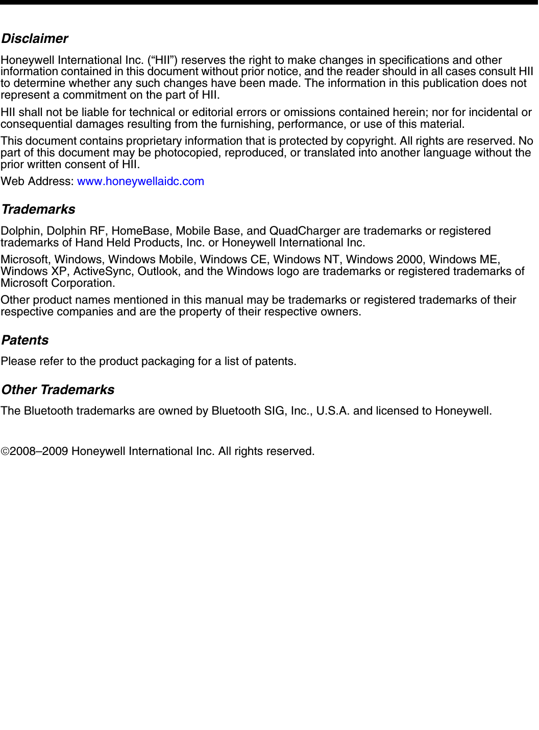
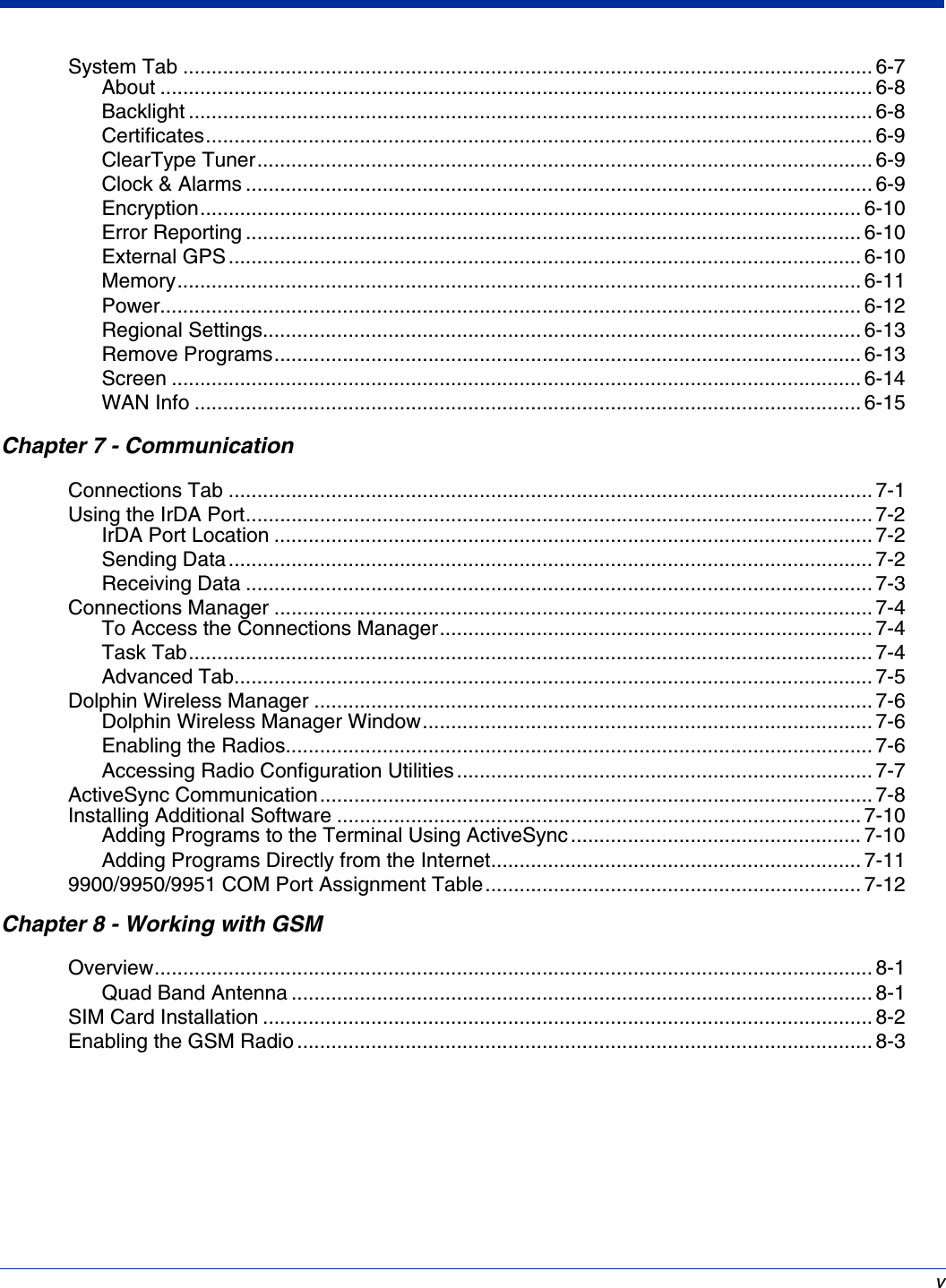

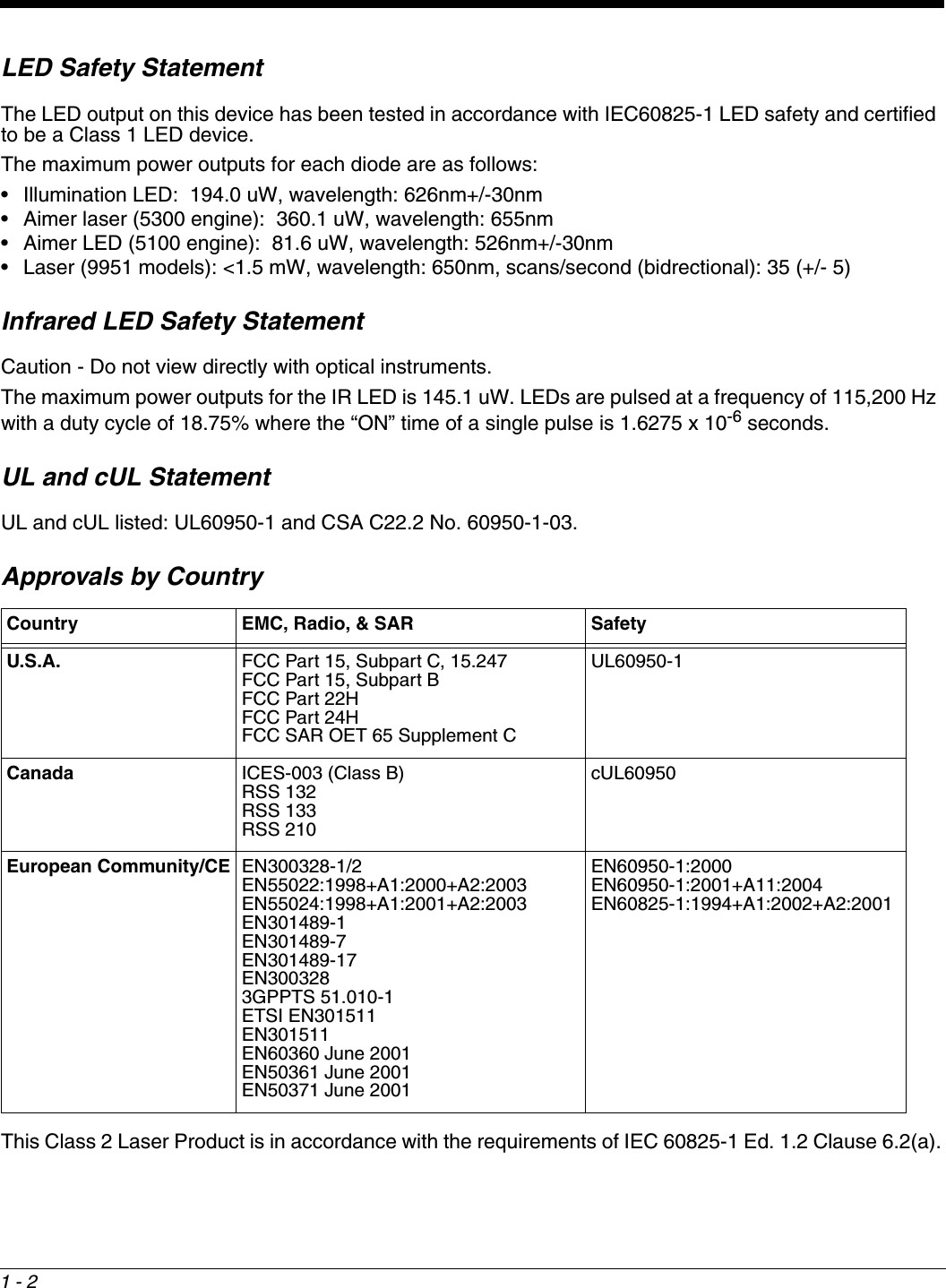

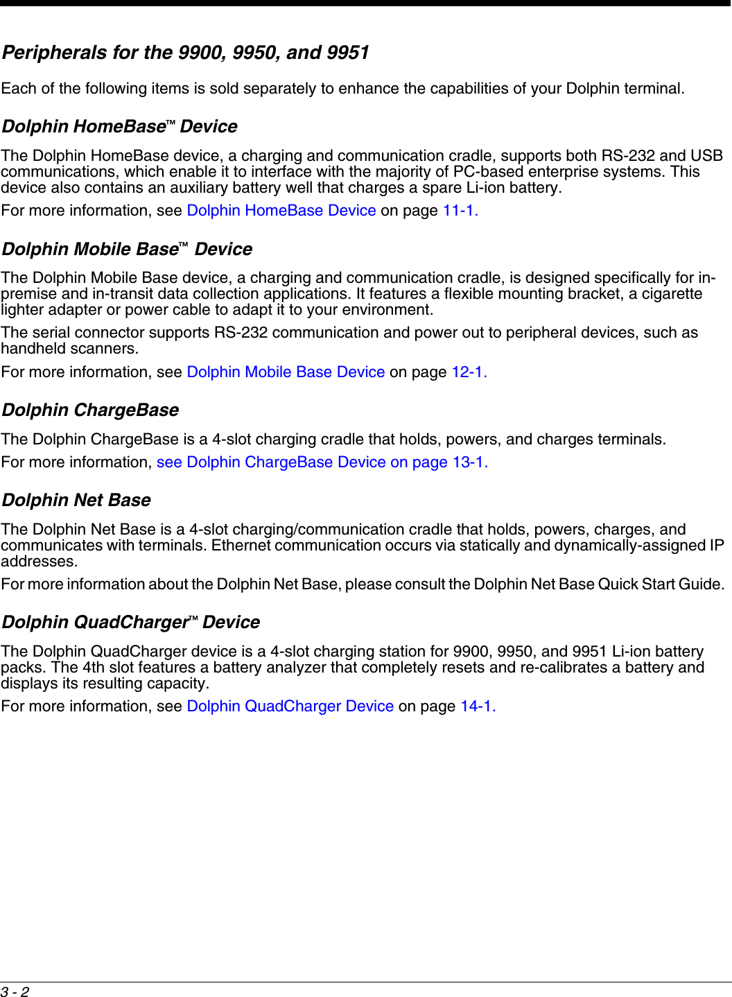
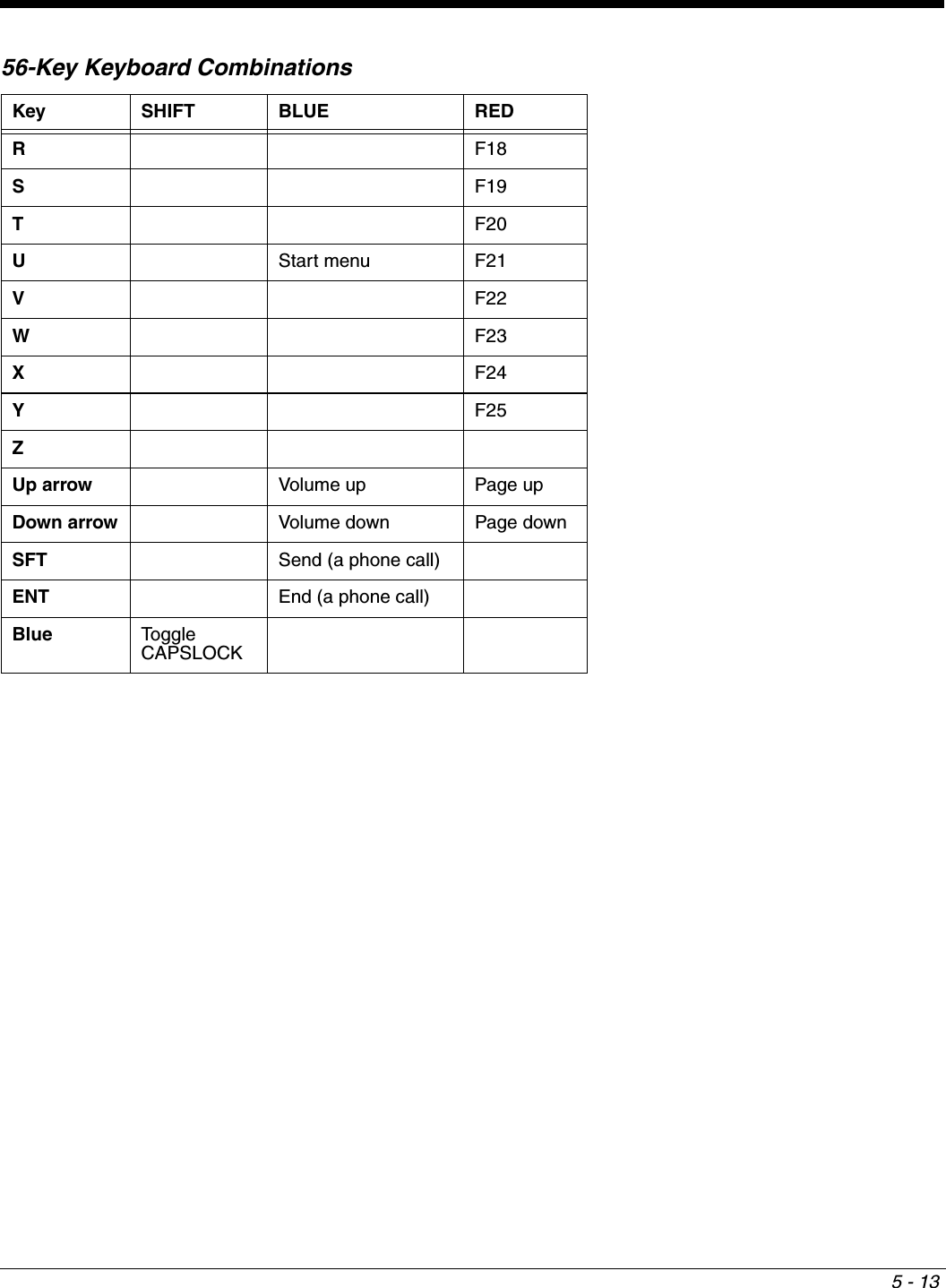
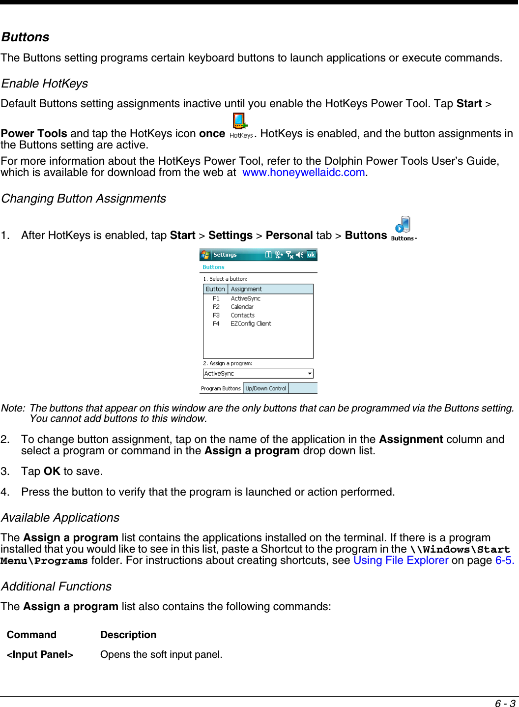
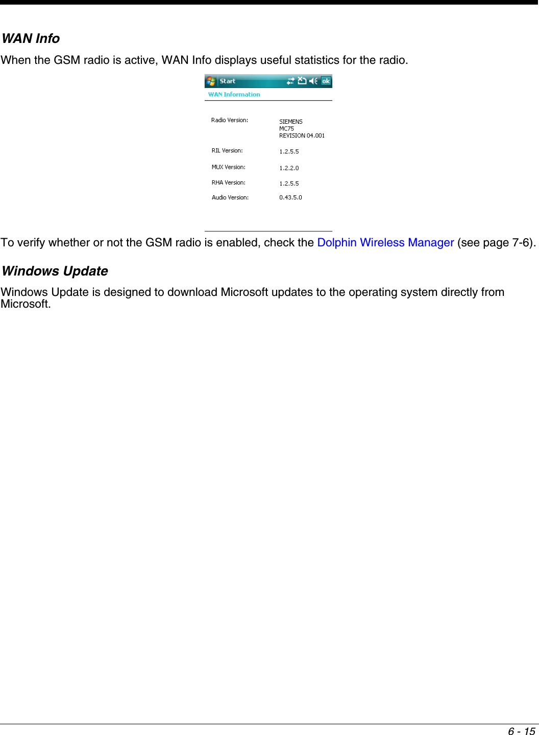
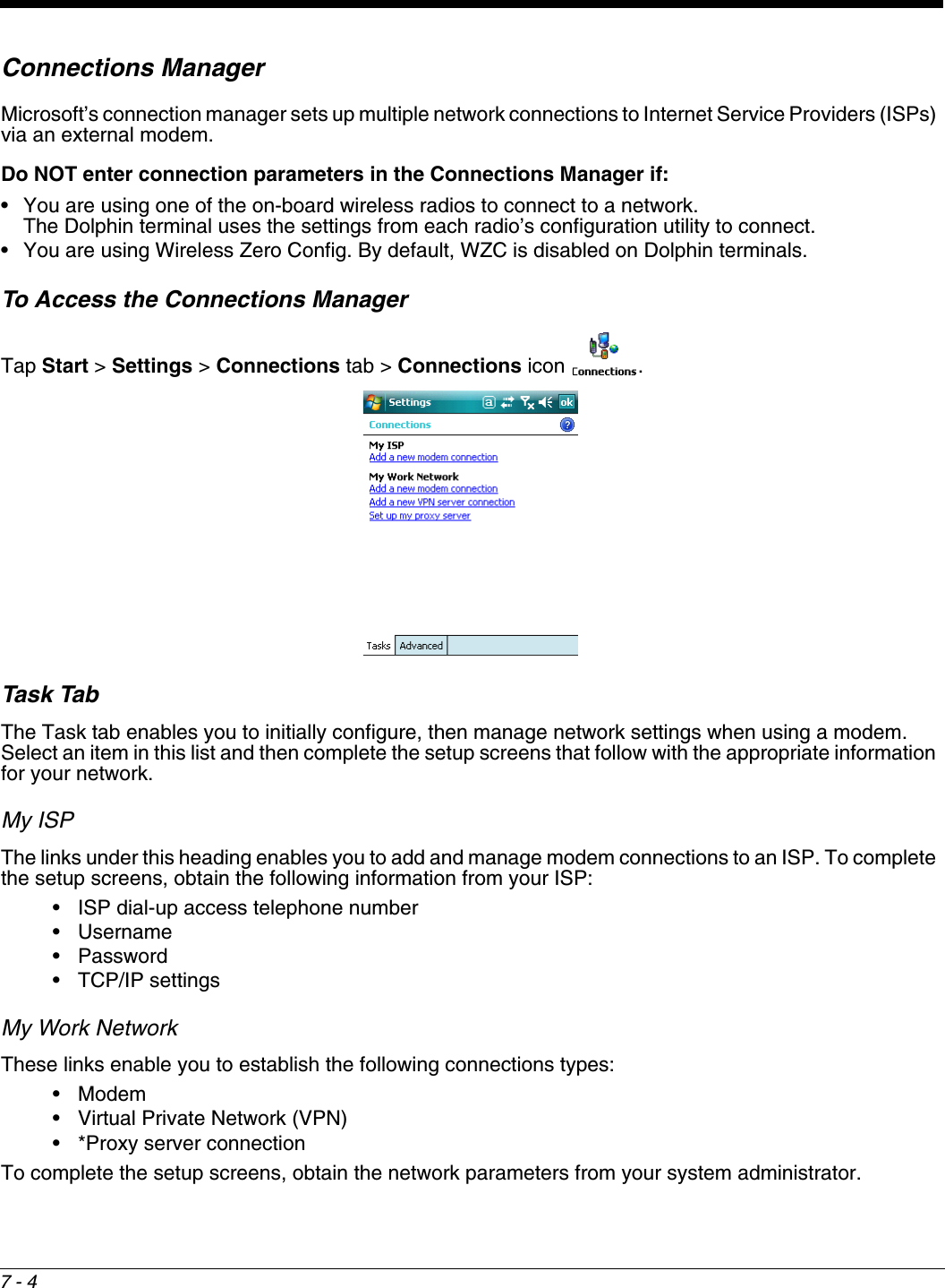
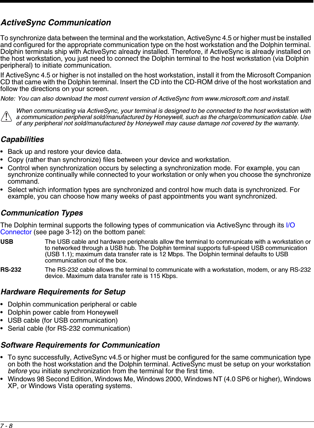
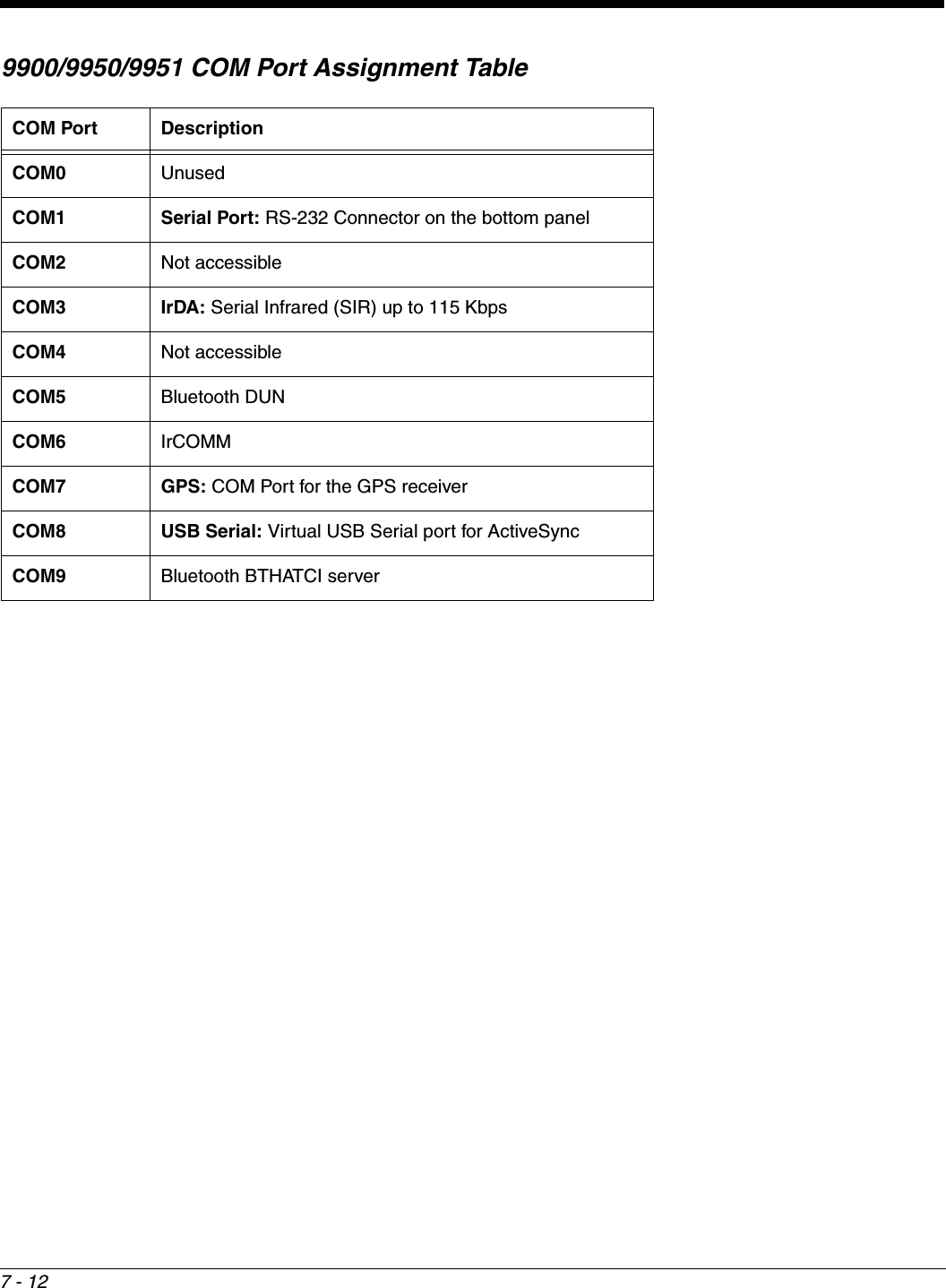
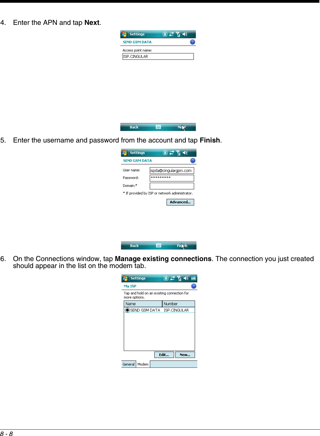
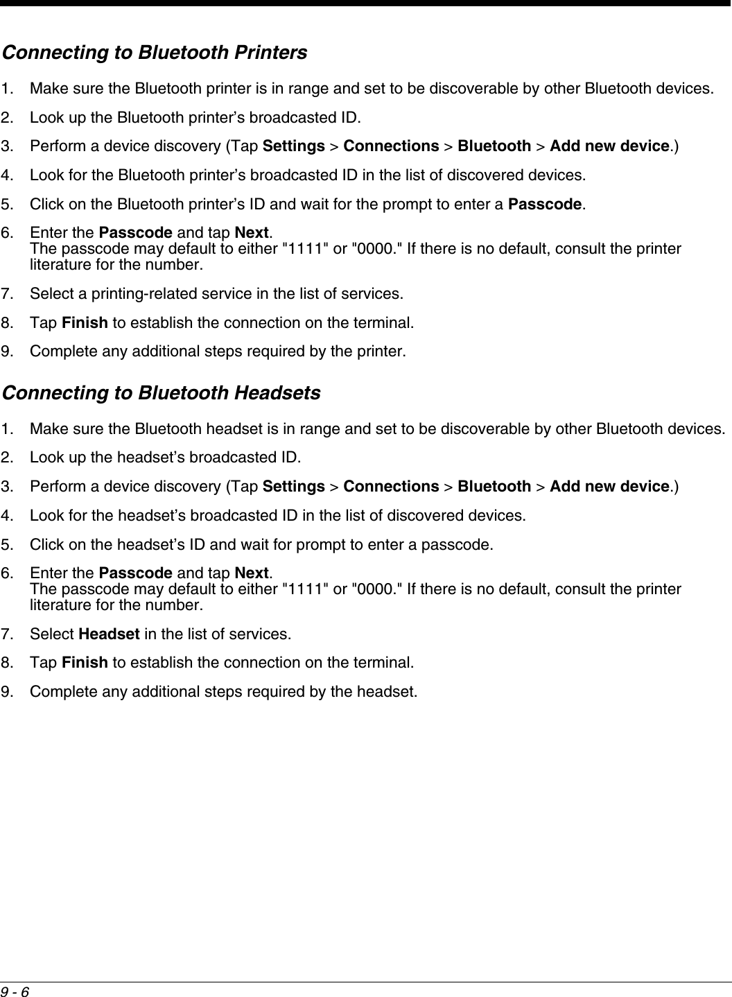
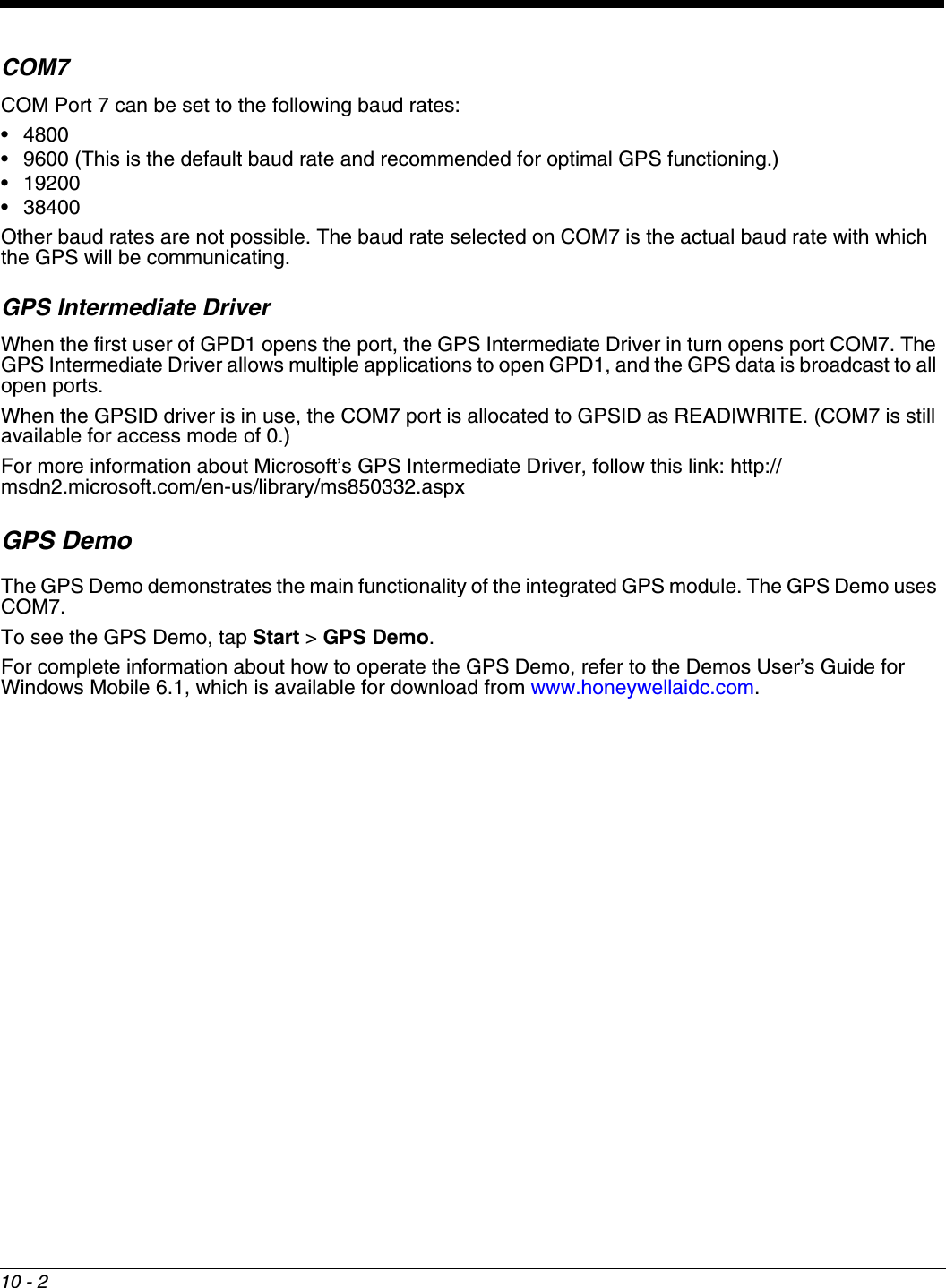
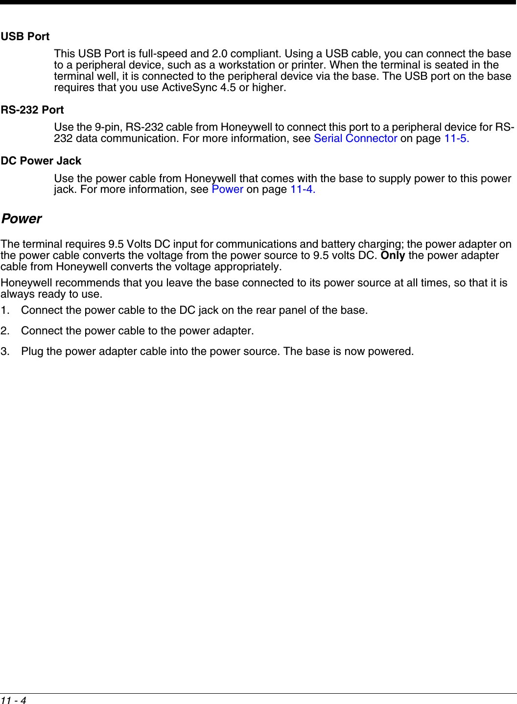
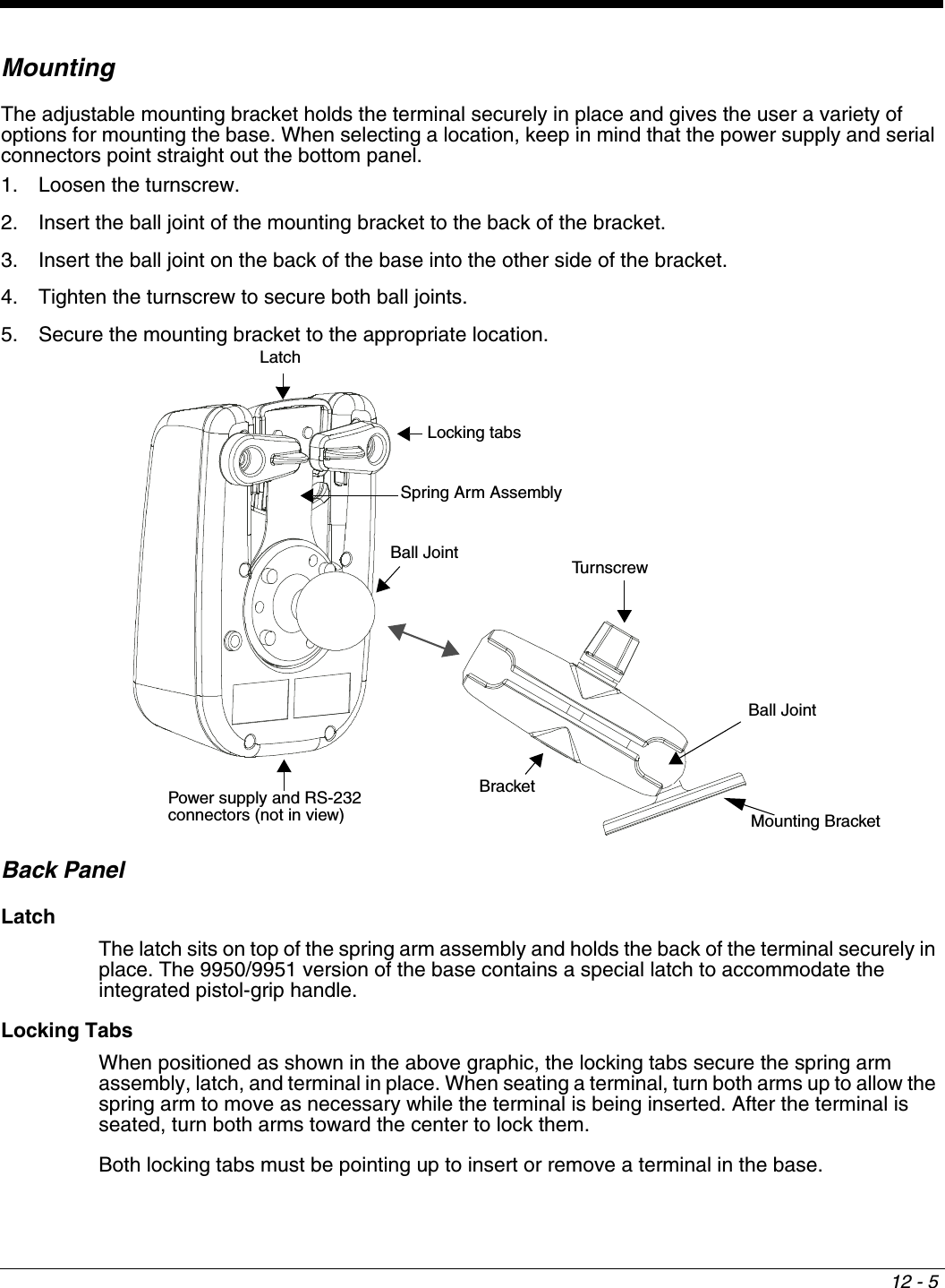
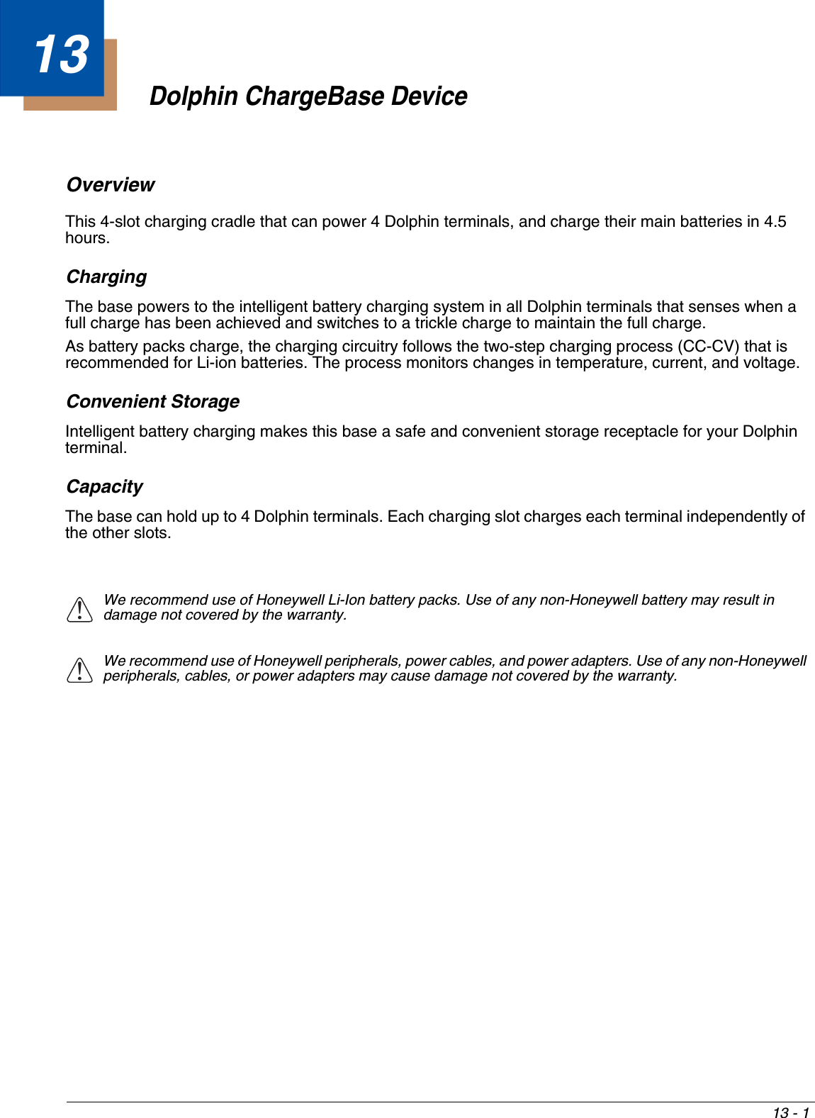
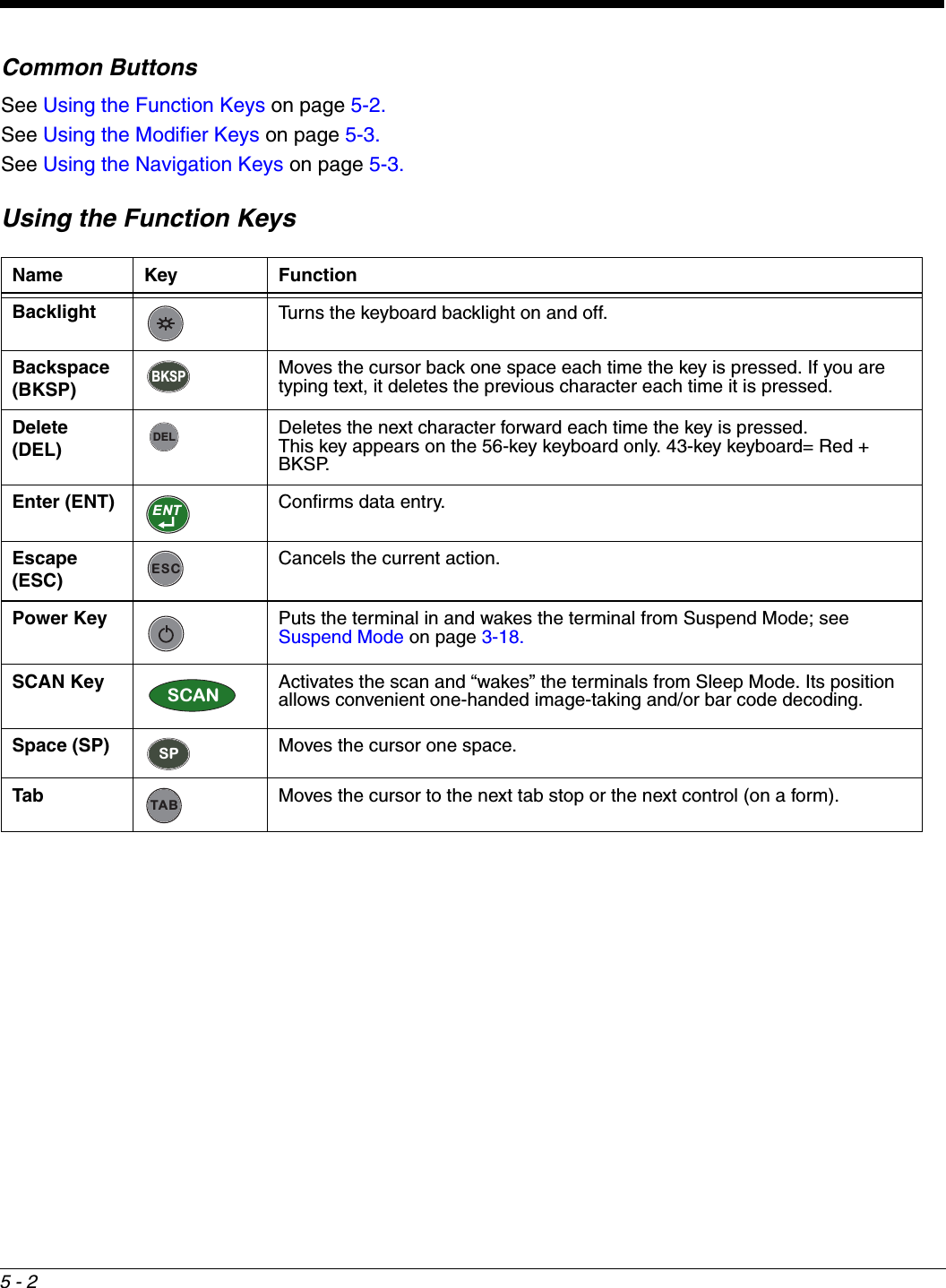
![3 - 12Bottom Panel: 9900, 9950, and 9951I/O ConnectorThe I/O connector powers the terminal, charges the main battery, and facilitates communication. All Dolphin peripherals are designed to work exclusively with this connector.The I/O connector supports RS-232 and USB communication. For RS-232, the maximum communication speed is 115 Kbps with seven baud rate settings. For USB, the communication speed is up to 12 Mbps. Powering OutThe I/O connector also provides power out (to peripheral devices) 5V at 500mA. This means that, with the proper cable, the terminal can power another device. By default, power out is disabled. To enable power out, alter the registry as follows: [HKEY_LOCAL_MACHINE\Drivers\BuiltIn\Serial4]Conn5Venable=1I/O ConnectorNote: Signals referenced are for a DTE device.](https://usermanual.wiki/Honeywell/9900B0P/User-Guide-1436905-Page-30.png)
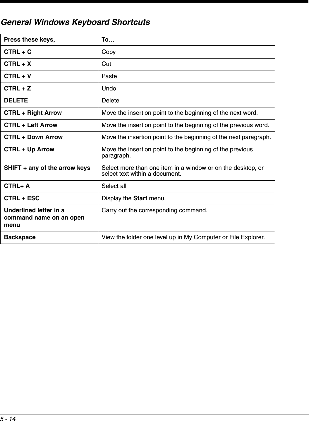
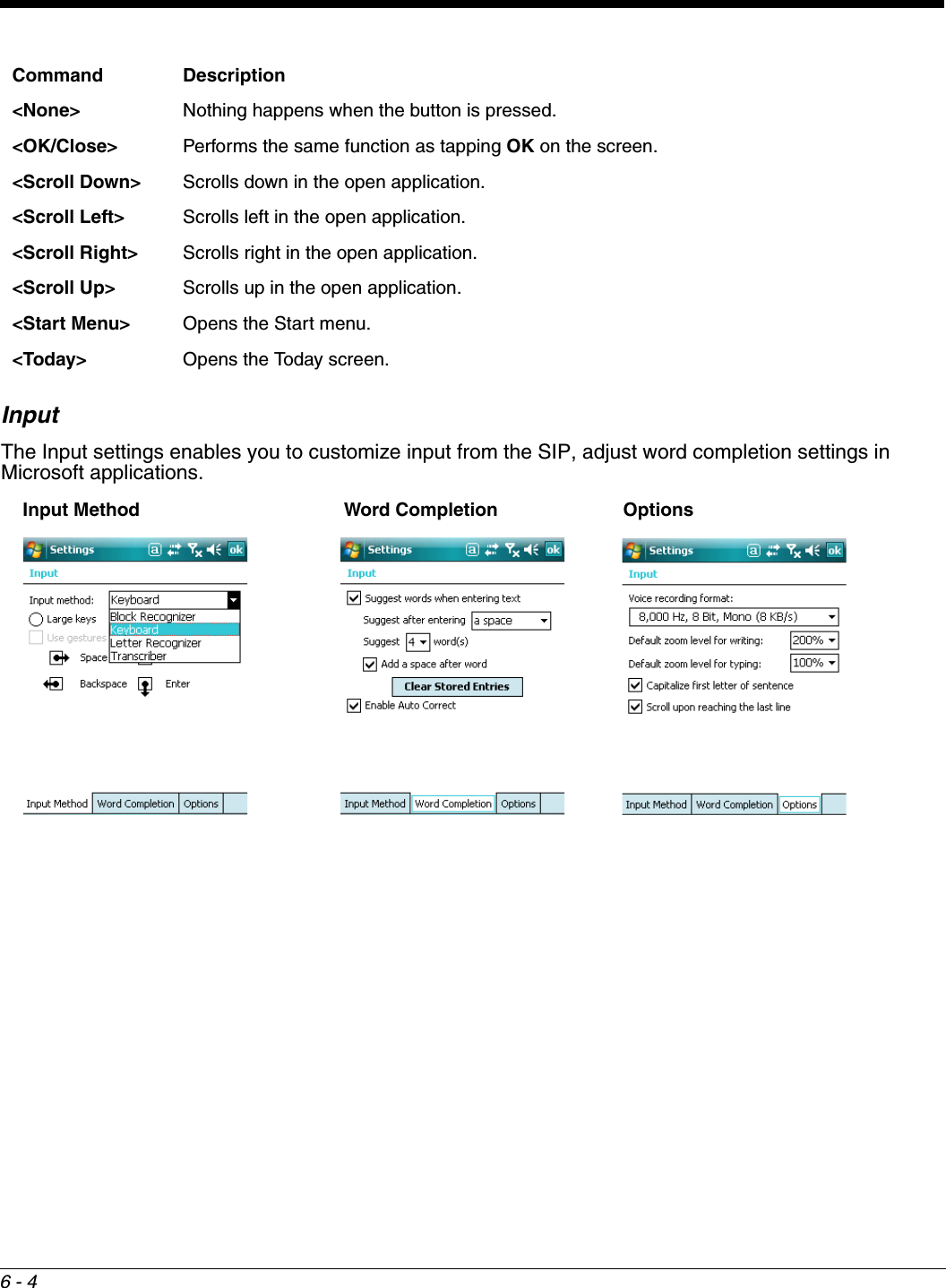
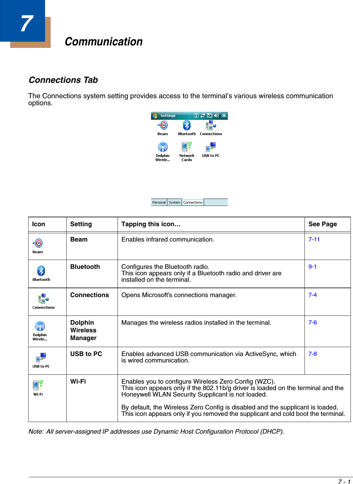
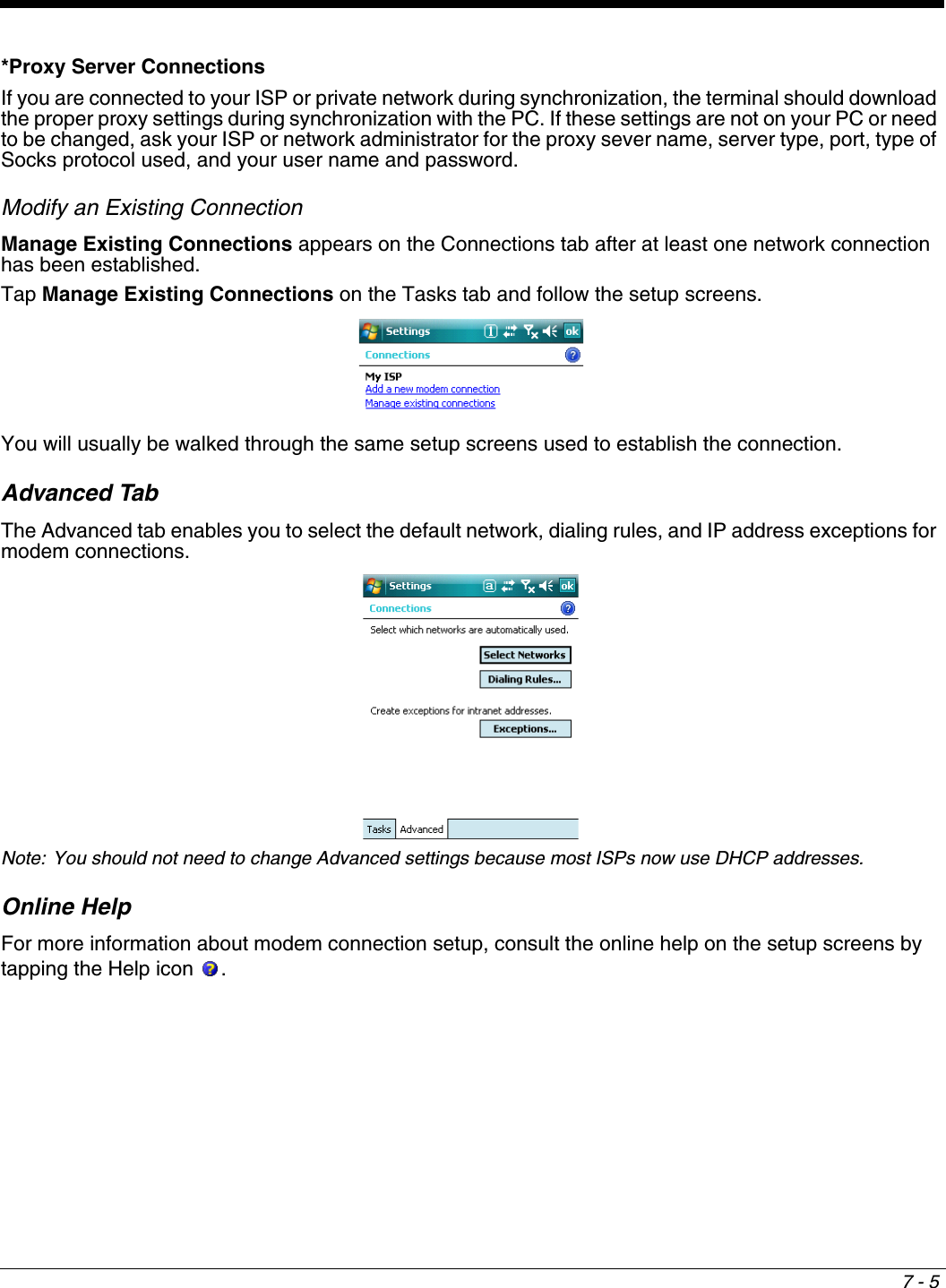
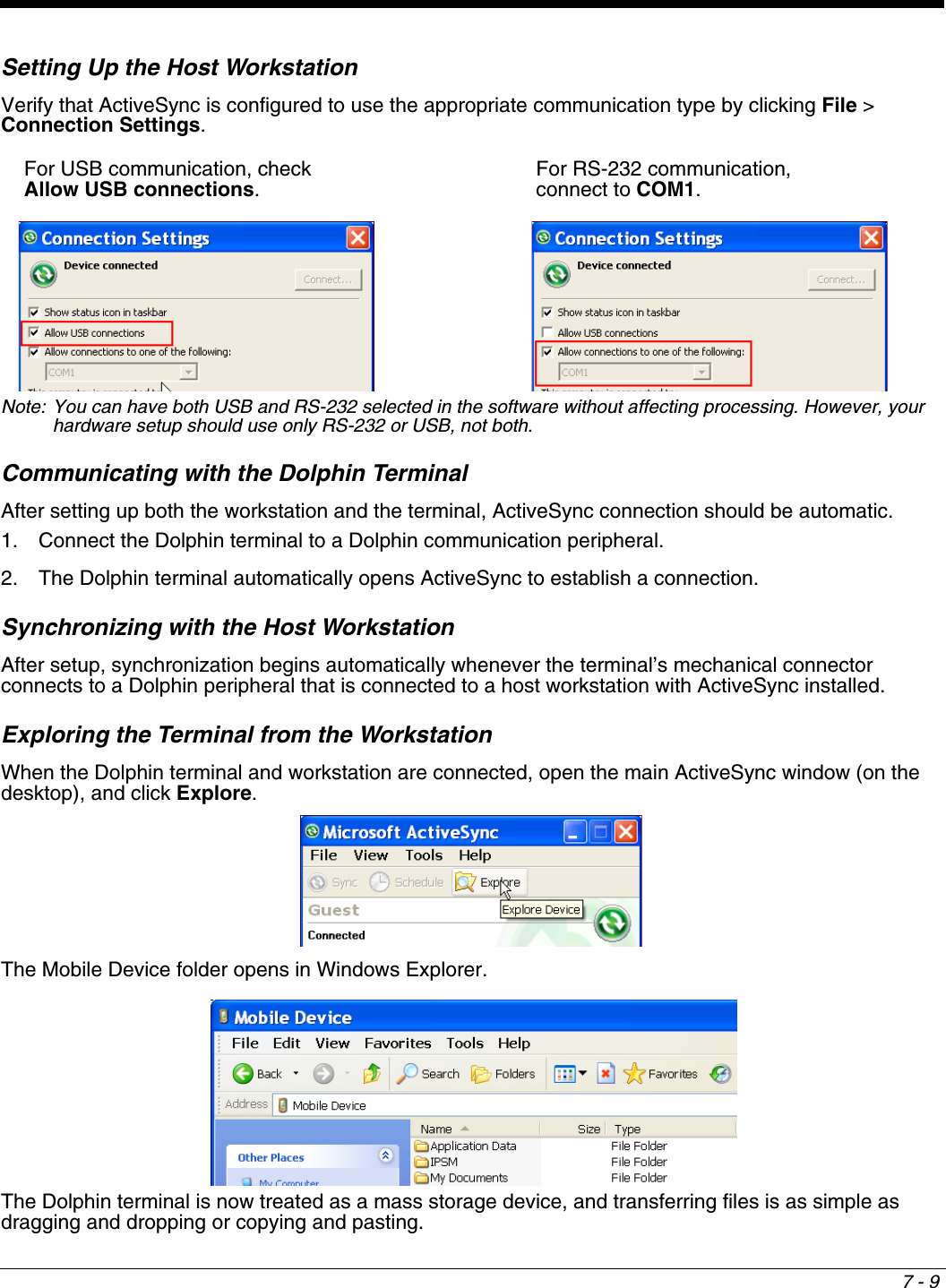
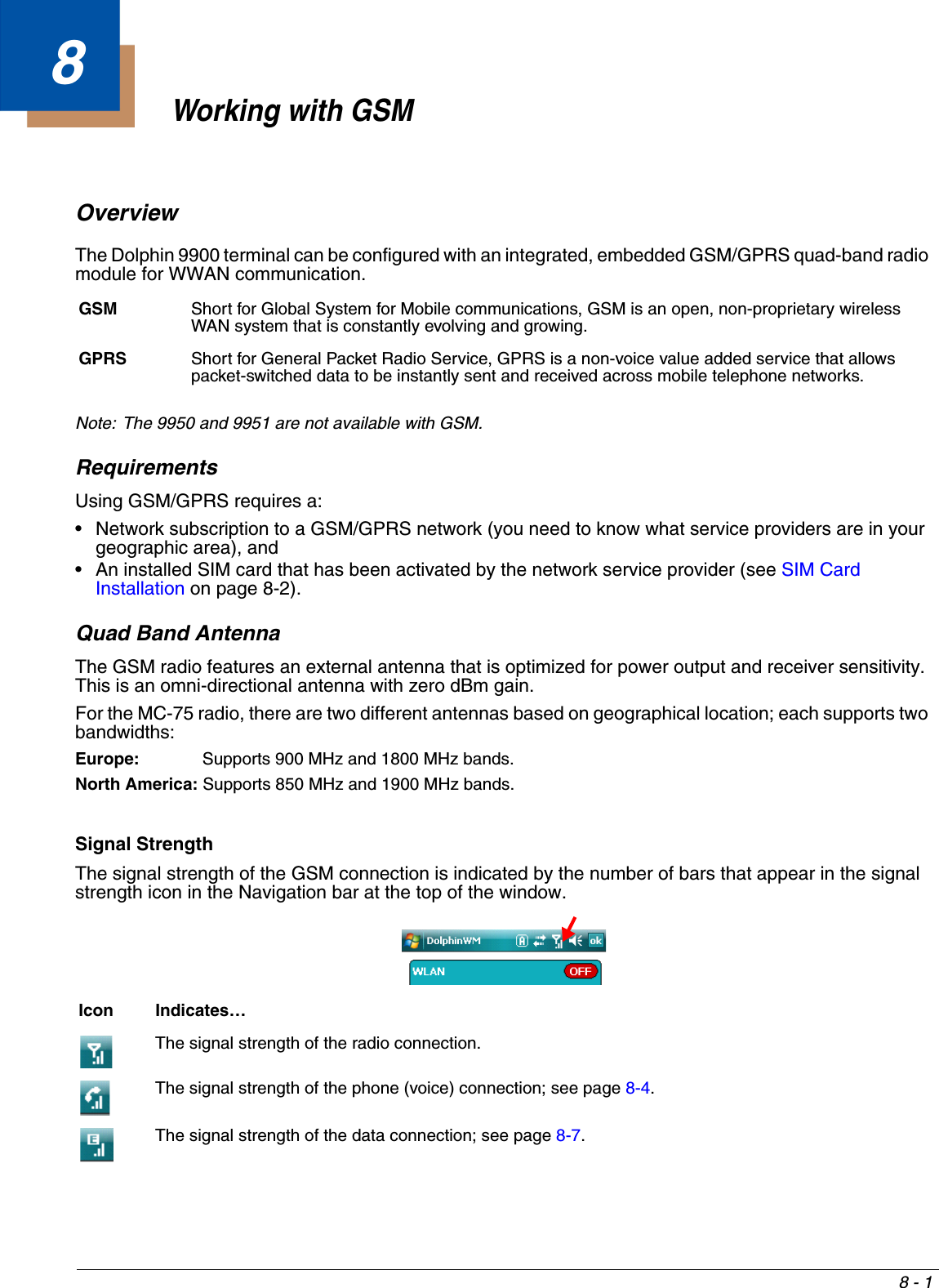
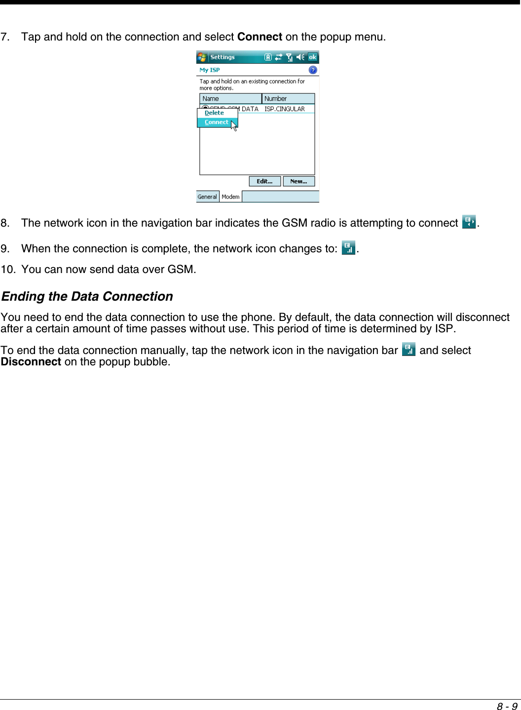
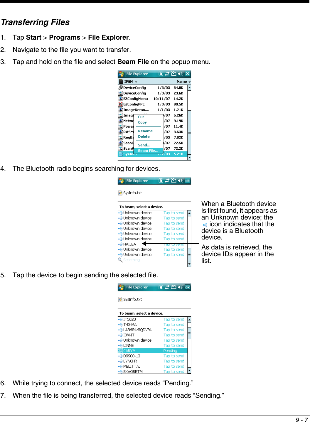
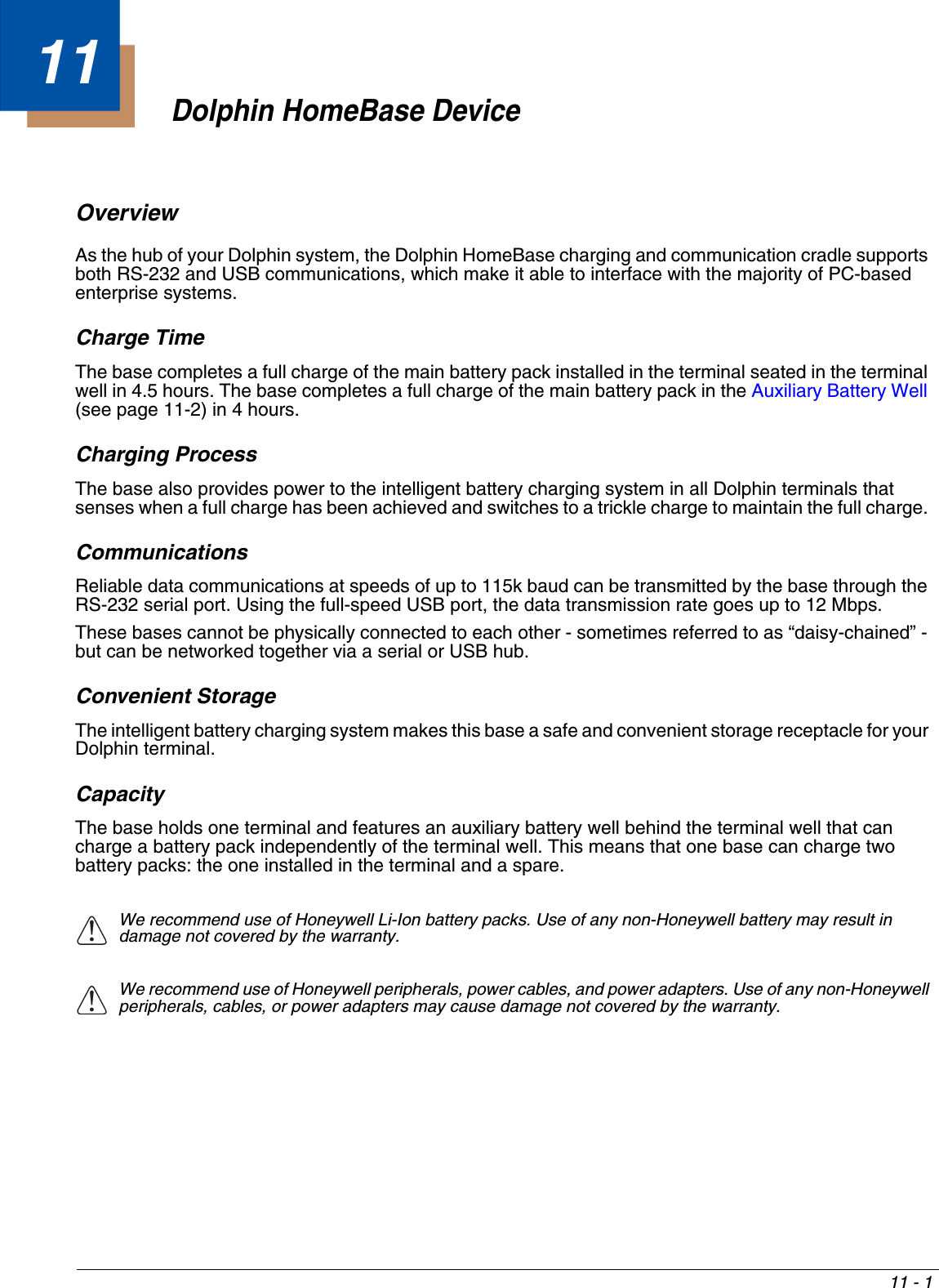
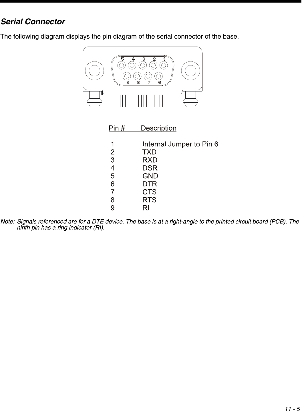
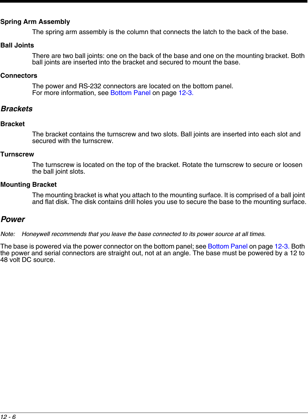
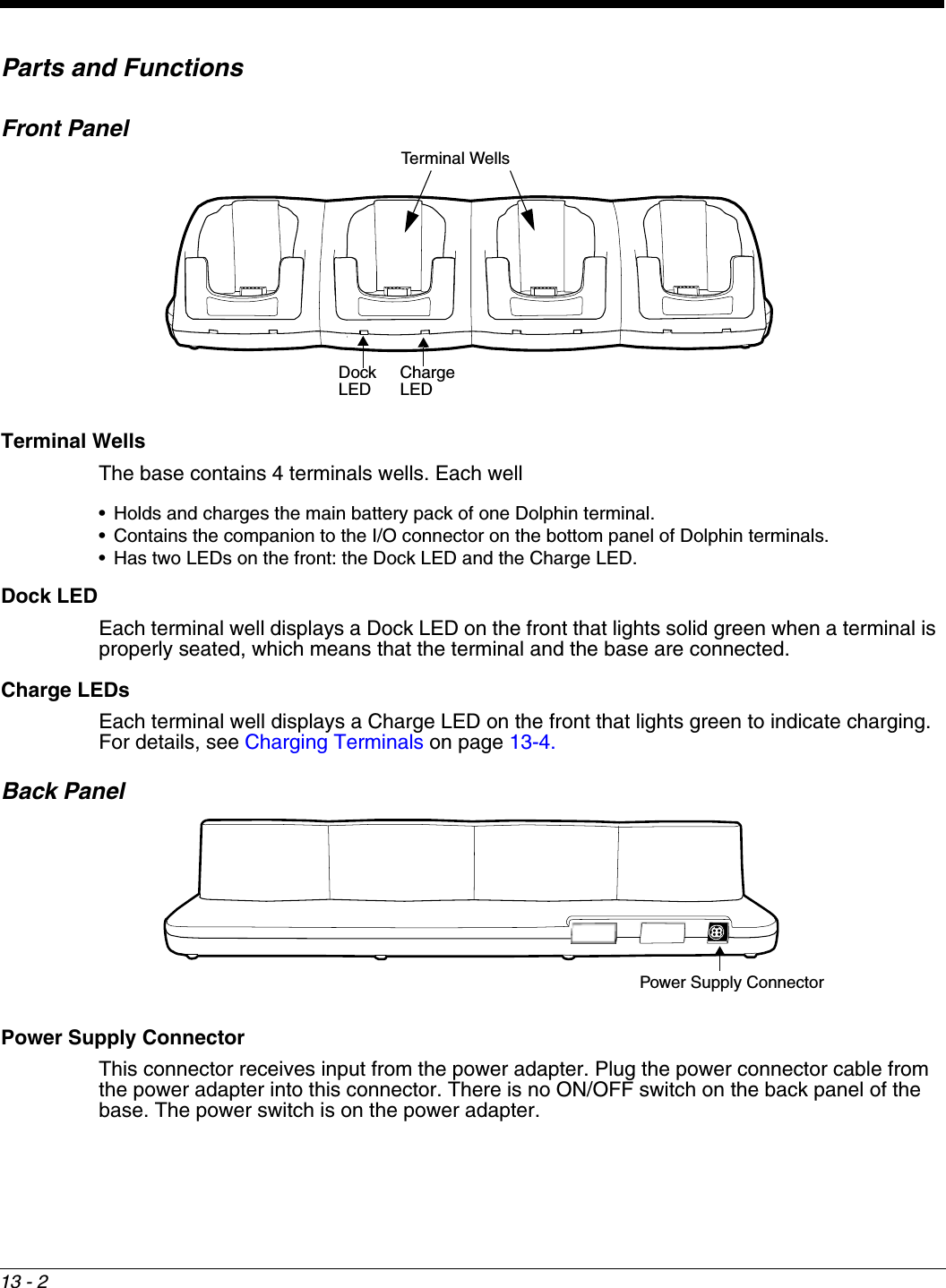
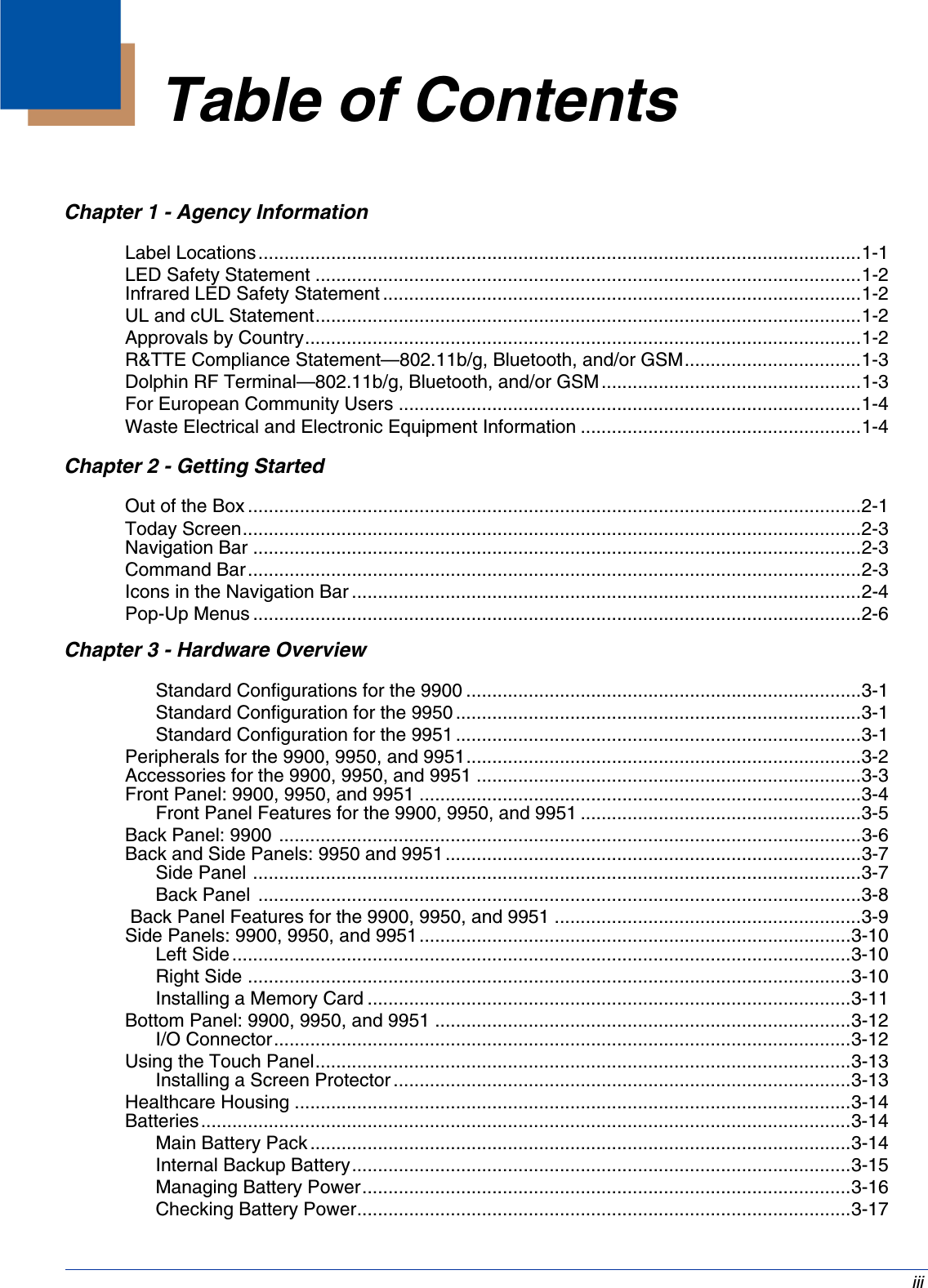
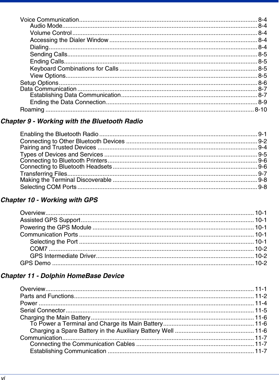
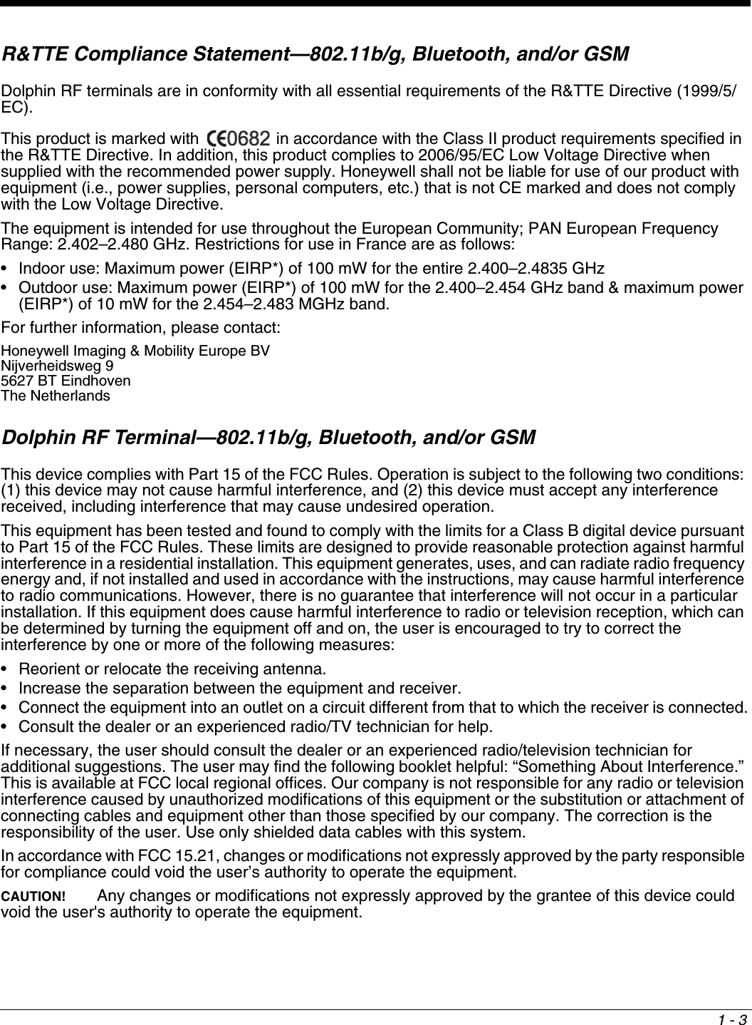
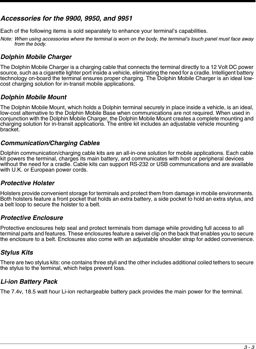
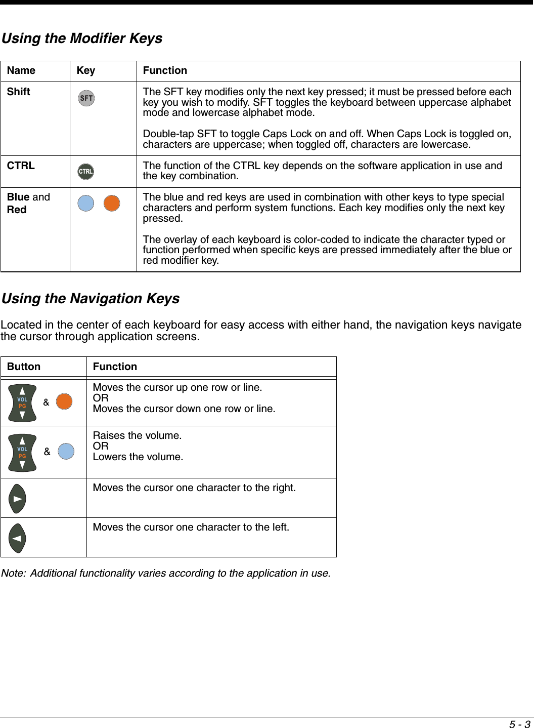
![3 - 16Guidelines for UseFollow these guidelines to maximize the life of the internal backup battery:• Keep a charged Li-ion battery pack in the terminal; the backup battery prematurely discharges if there is not at least a partially charged battery in the terminal.• Keep the terminal connected to power when the terminal is not in use. Managing Battery PowerData and files saved on Dolphin terminals may be stored in RAM memory, which does not persist through a hard reset. Therefore, to help prevent data loss, maintain a continuous power supply to the terminal. Letting the backup battery become fully discharged causes the terminal to lose all data in RAM. Therefore, you should keep a charged battery pack in the terminal at all times. The internal battery discharges prematurely if there is not at least a partially charged battery in the terminal. When you remove a battery pack, insert another charged battery pack in the terminal immediately. Default Critical and Low Battery PointsWhen the terminal is running on battery power (as opposed to external power), warnings are displayed when the battery reaches critical and low battery points. The warning points are determined by the following registry entry: [HKEY_LOCAL_MACHINE\System\CurrentControlSet\Control\Power] There are two DWORD values in this registry entry: LowBatt and CriticalBatt. The default values for these entries are as follows:LowBatt=19 (25%)This sets the Low Battery point to 25% (19 hex=25 decimal). When the battery hits the percentage charge specified here, the user is notified by this icon in the Navigation bar .If the main battery is low and the terminal is in Suspend Mode, pressing the SCAN or Power button won’t wake the Dolphin terminal; you must replace the discharged battery with a battery charged over the 25% mark before you can resume terminal operation.CriticalBatt=a (10%)This sets the Critical Battery point to 10% (a hex= 0 decimal). When the battery hits the percentage charge specified here, the user is notified by this icon in the Navigation bar .Note: Warnings do not appear when the terminal is on external power.Setting Critical and Low Battery PointsDevelopers can reset these parameters in the registry from 0 (no warning) to 99 (would nearly always warn). You can review and set these battery points in the RegEdit Power Tool. 1. Tap Start > Power Tools > RegEdit. 2. Drill down to HKEY_LOCAL_MACHINE > System > CurrentControlSet > Control > Power.3. Tap the Value Name to change the Value Data. You can reset the Value Data from 0 (no warning) to 99 (would nearly always warn). 4. Tap OK to save changes.](https://usermanual.wiki/Honeywell/9900B0P/User-Guide-1436905-Page-34.png)

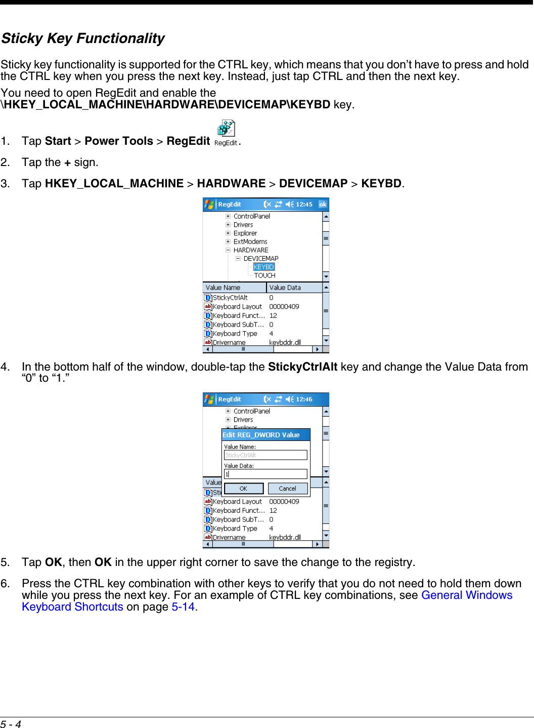
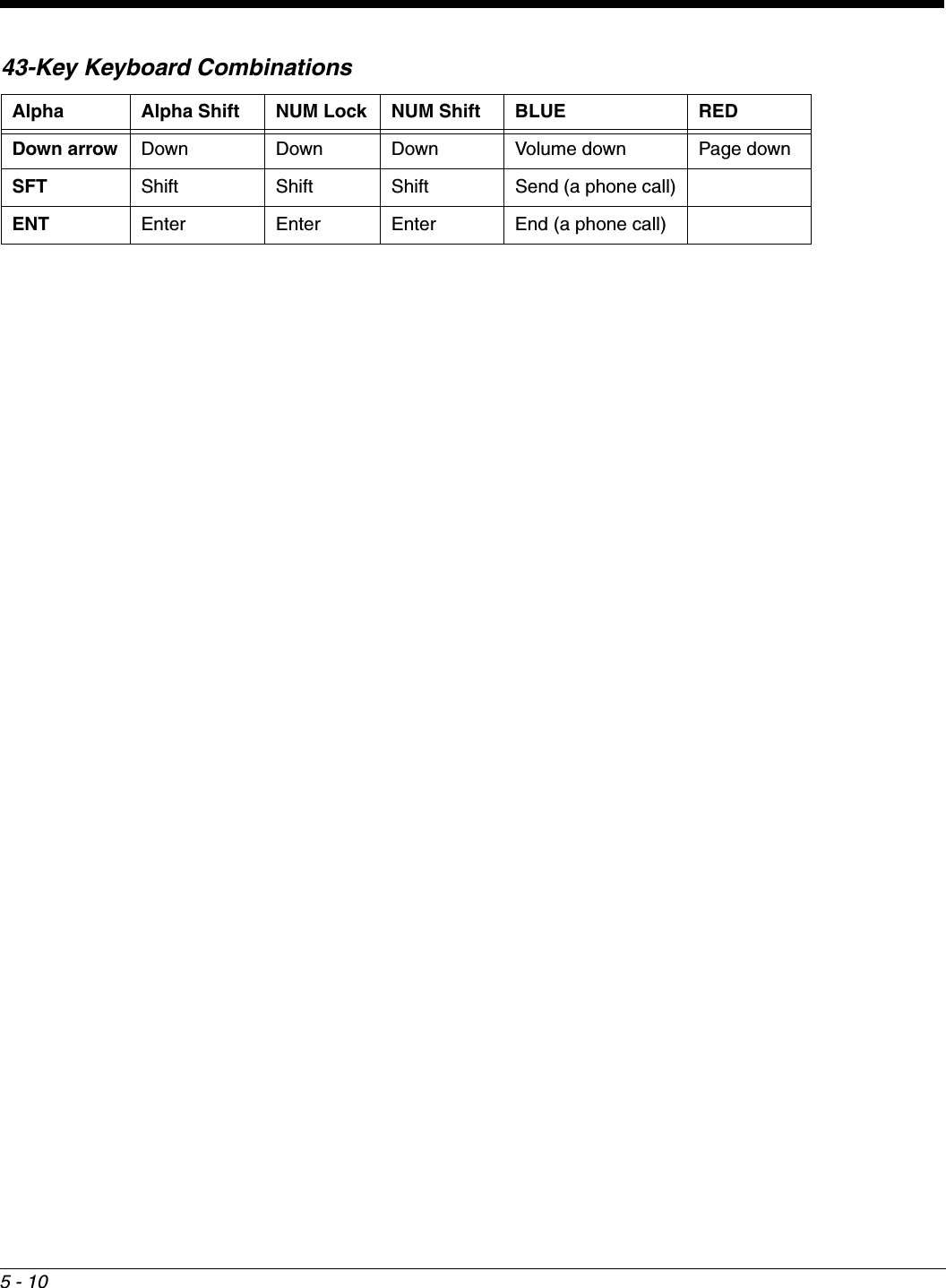
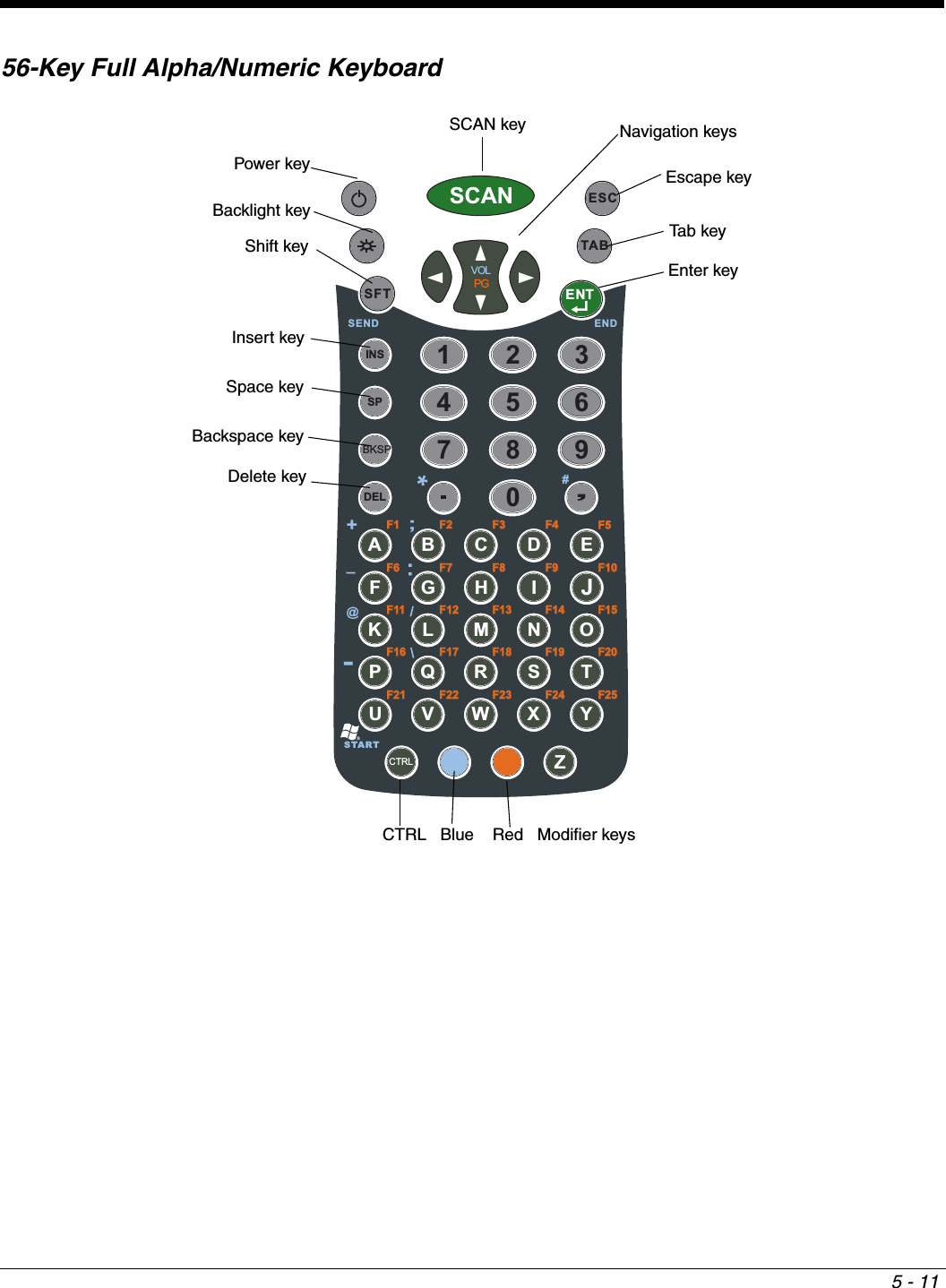
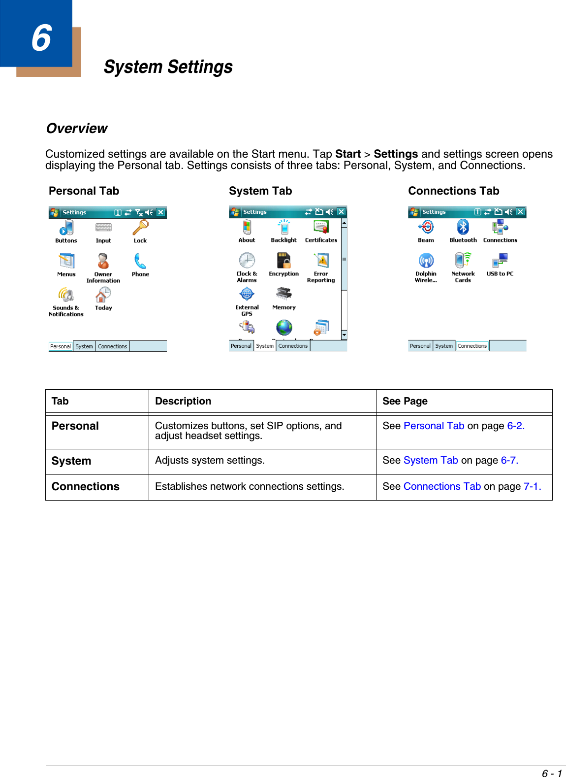
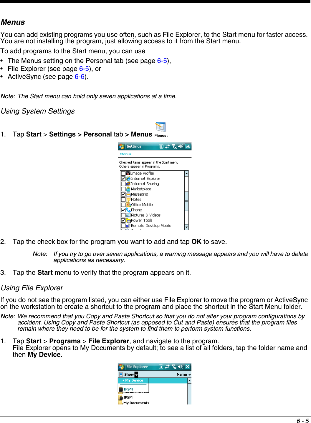
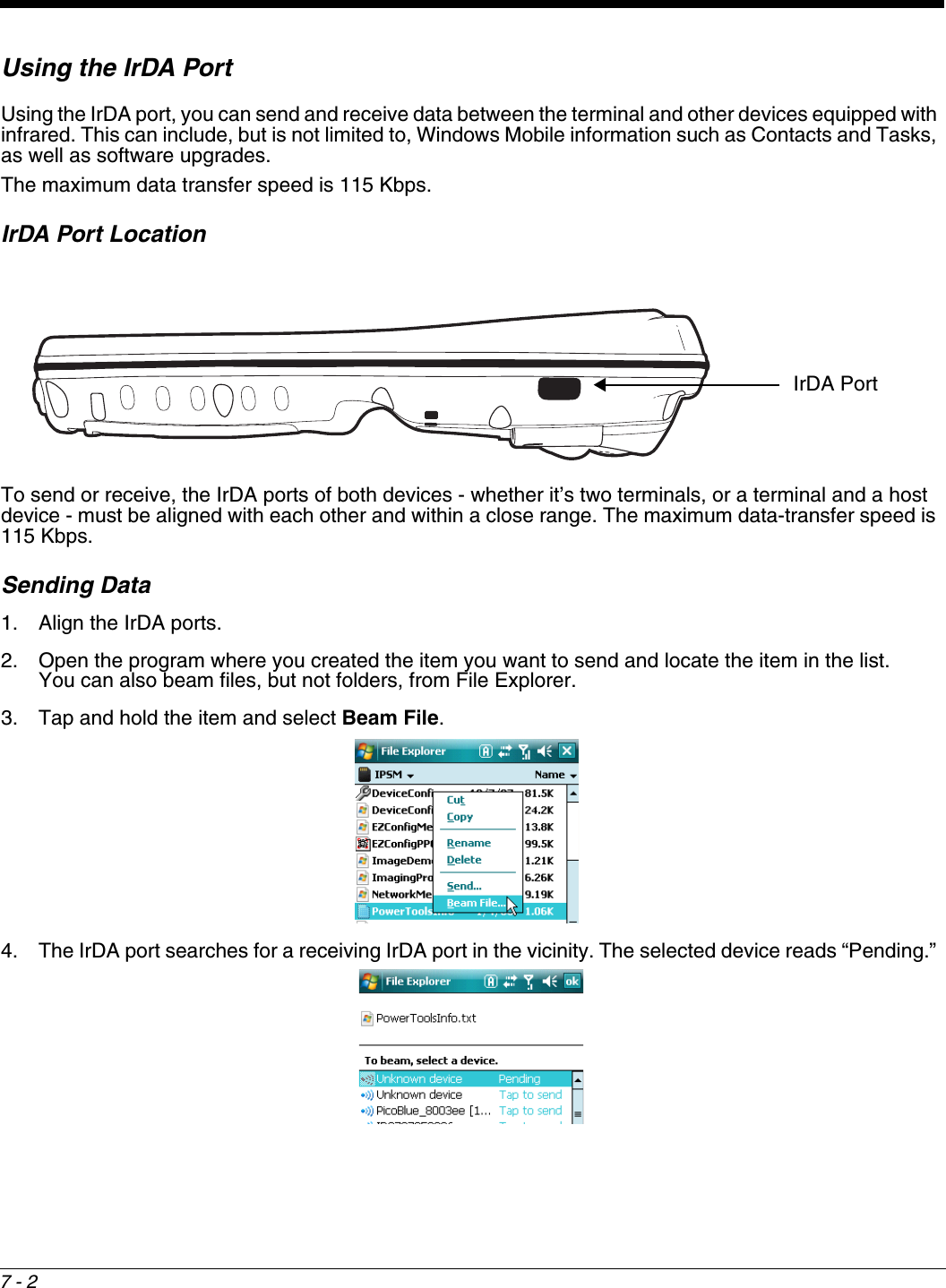
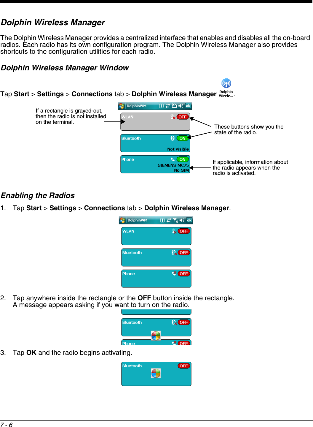
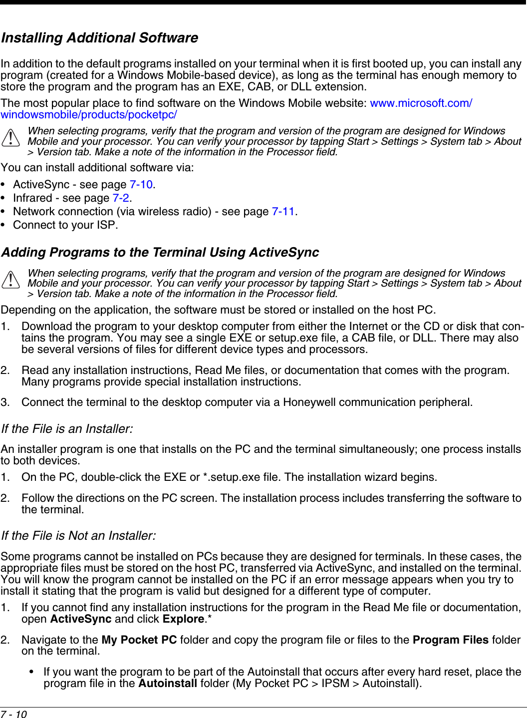
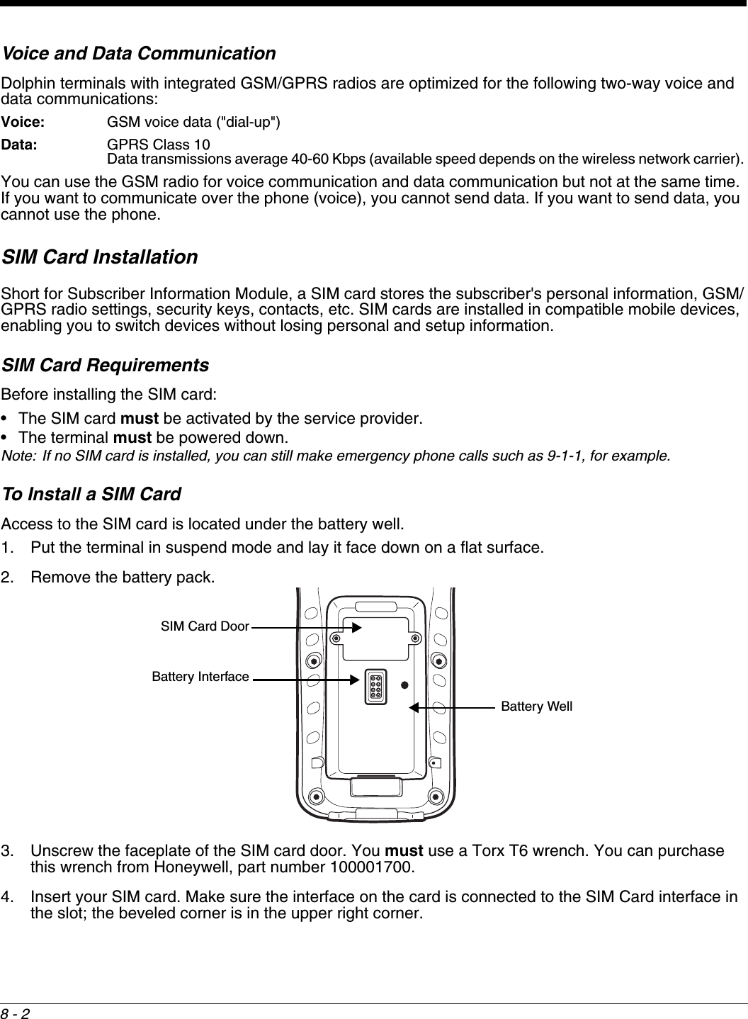
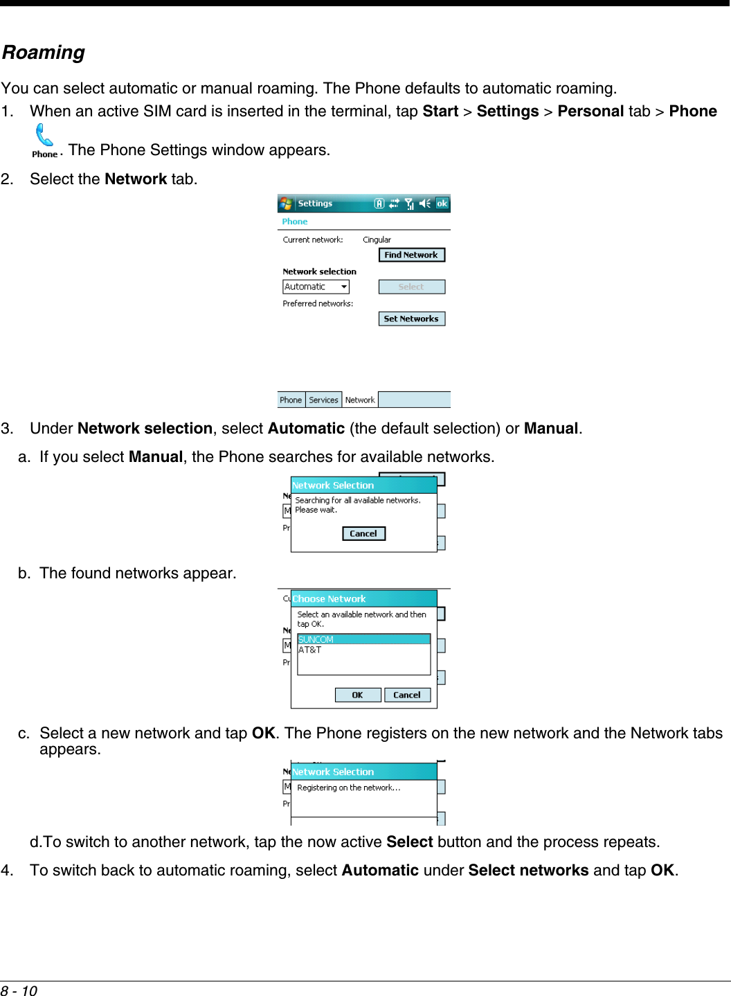
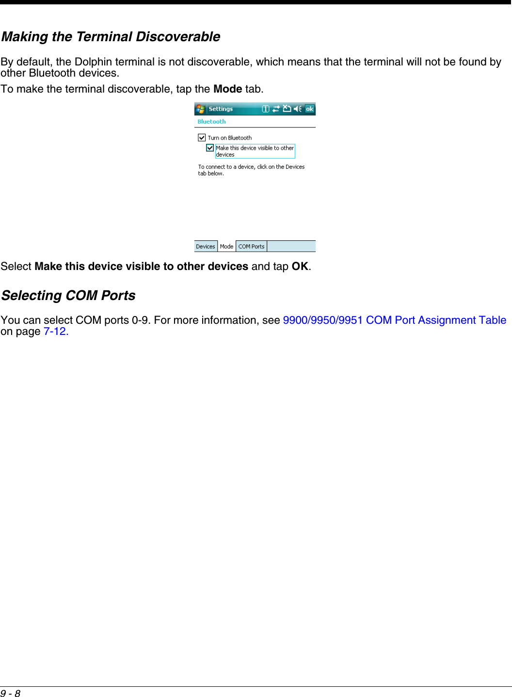
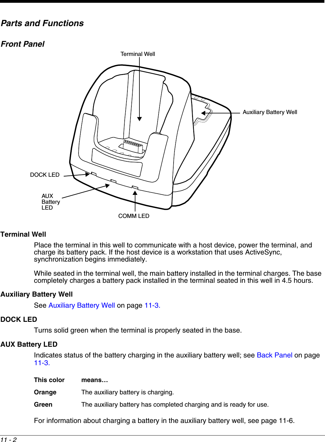
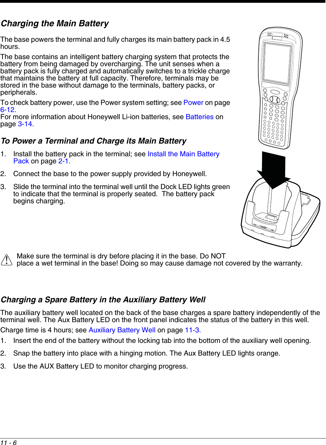
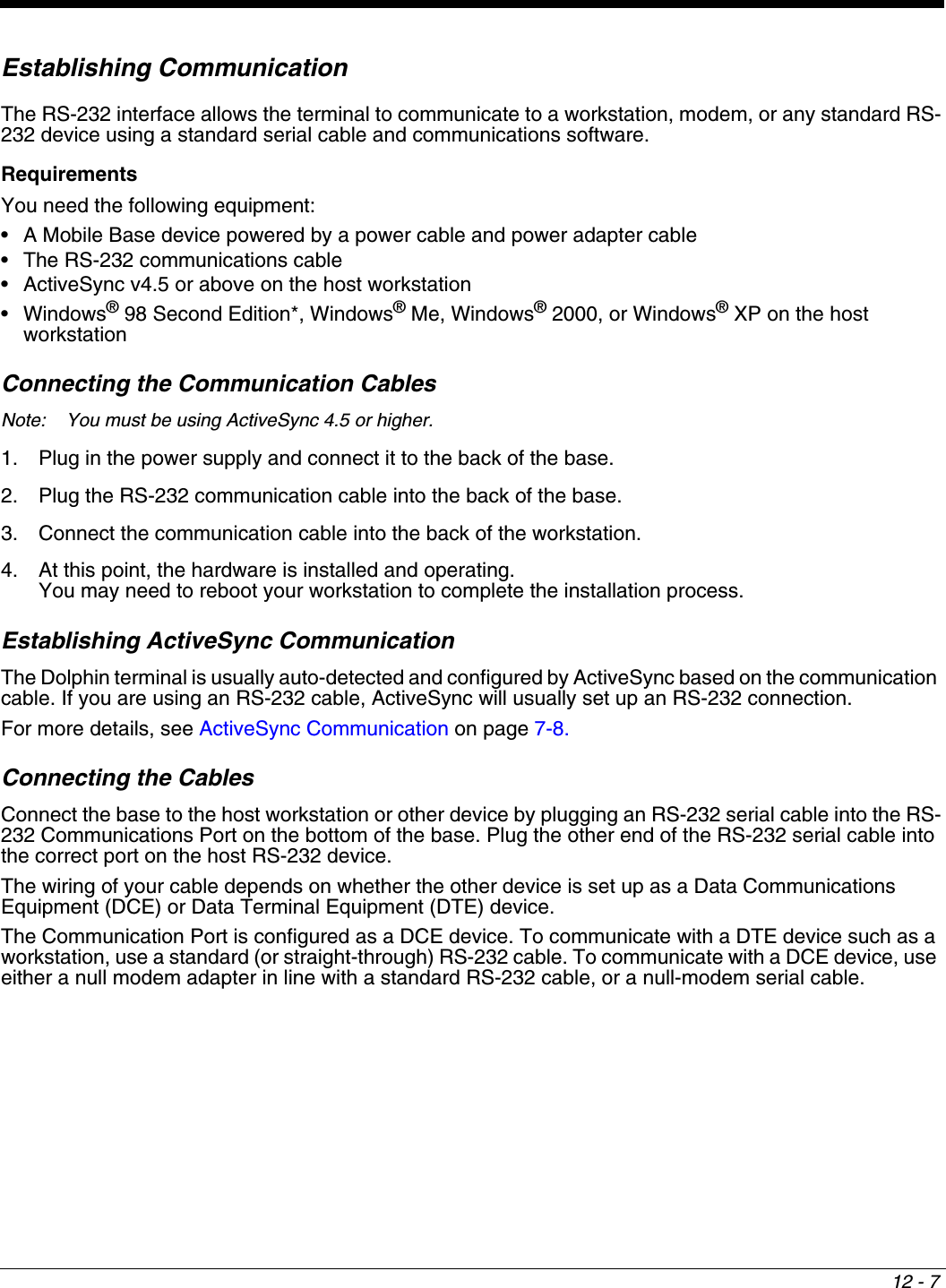
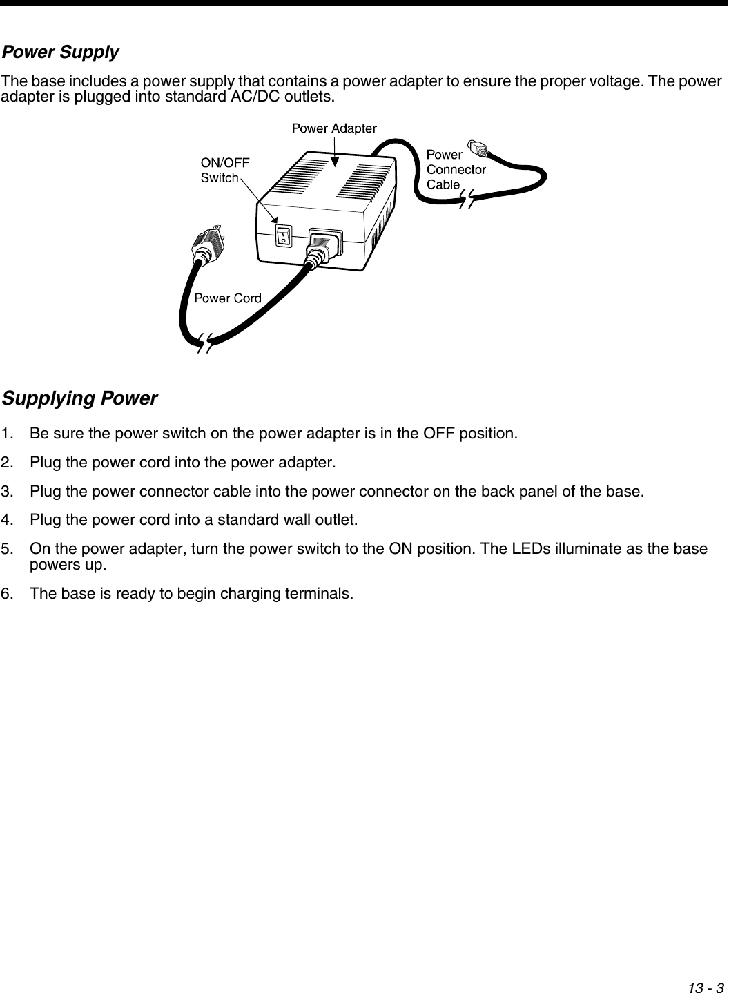
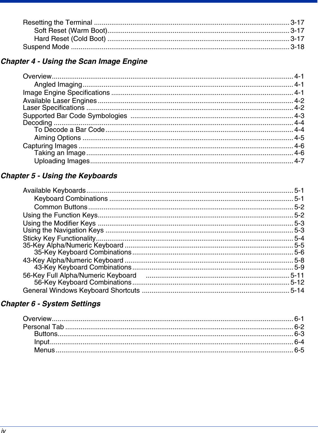
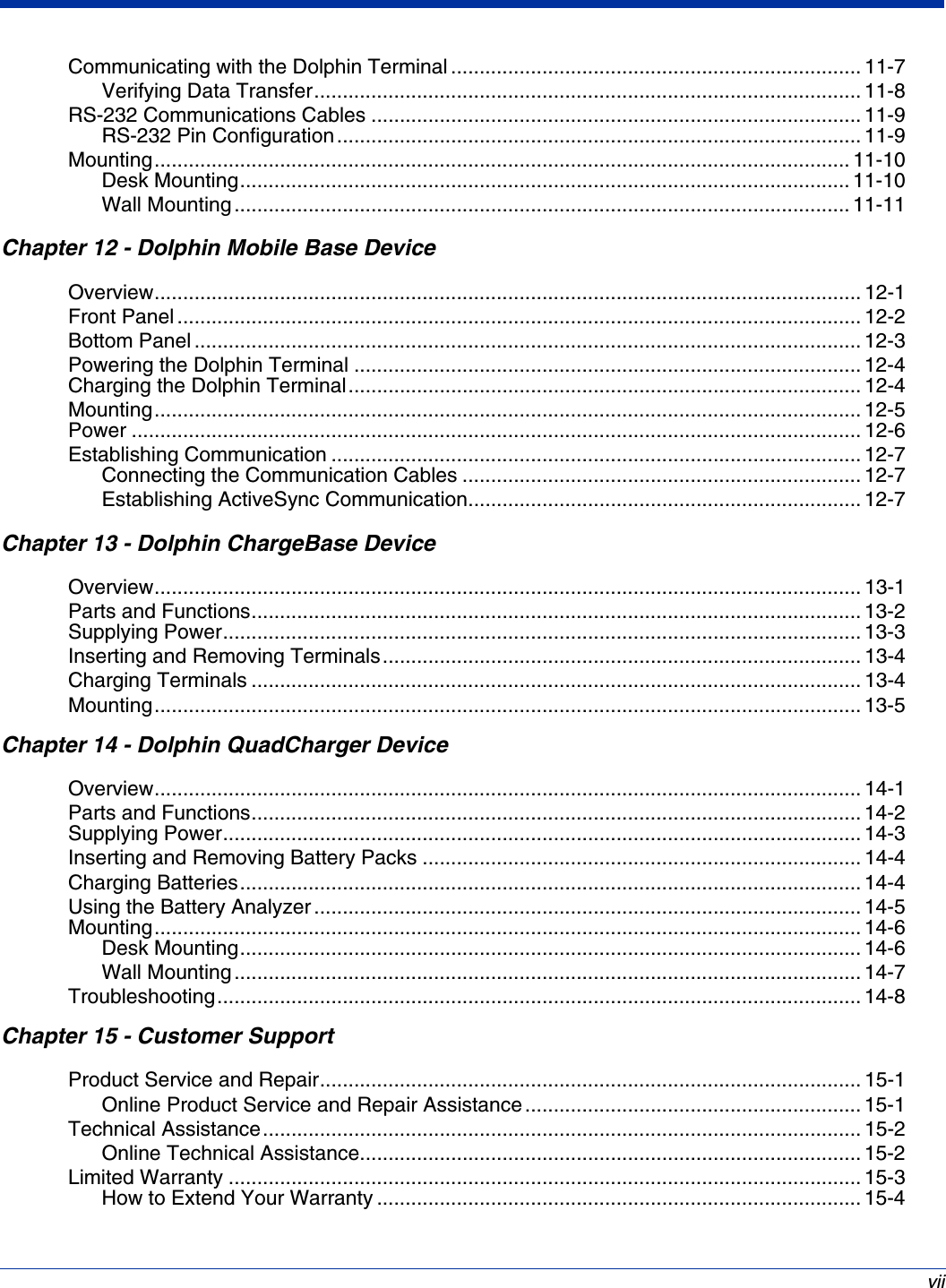
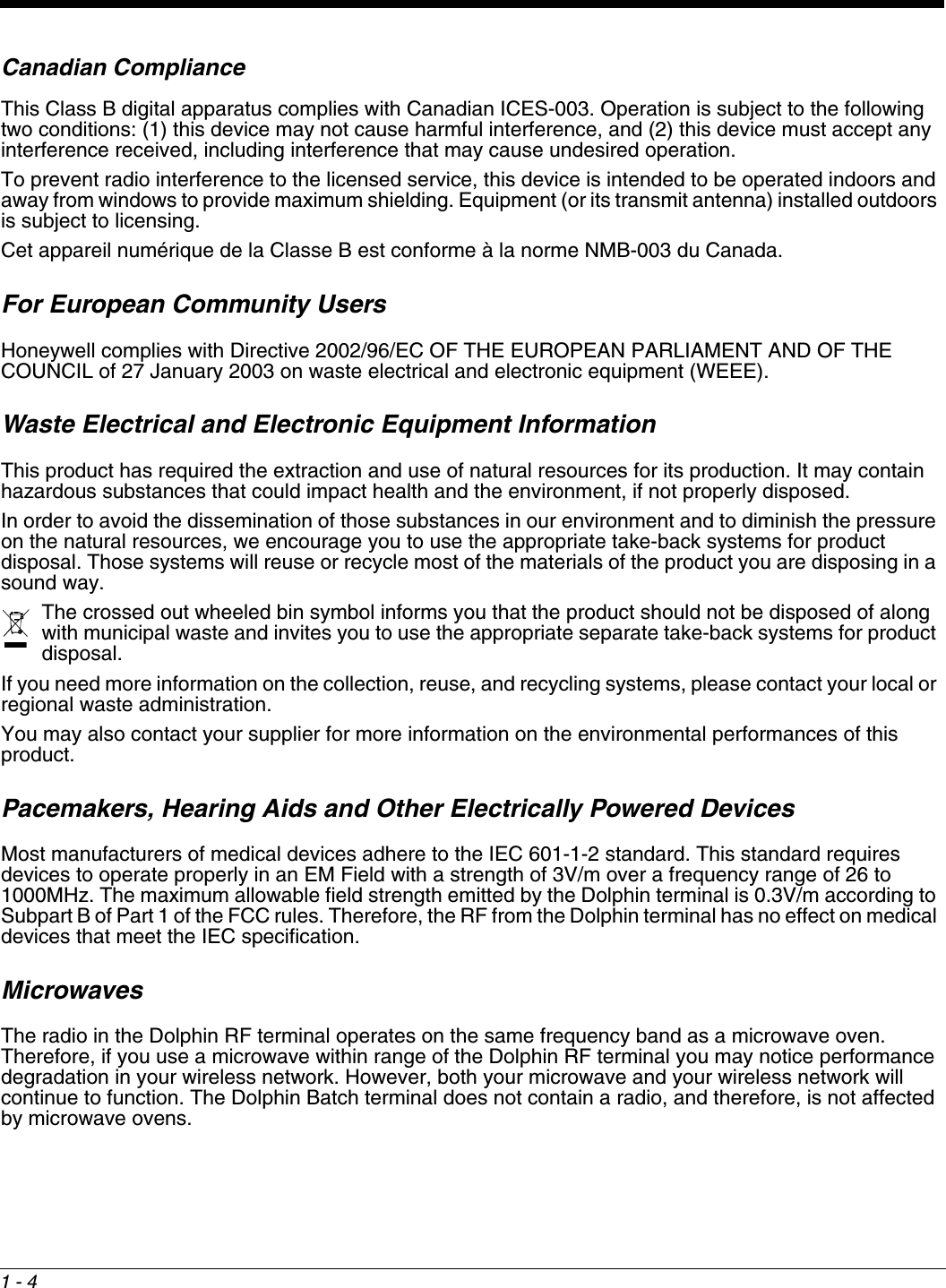
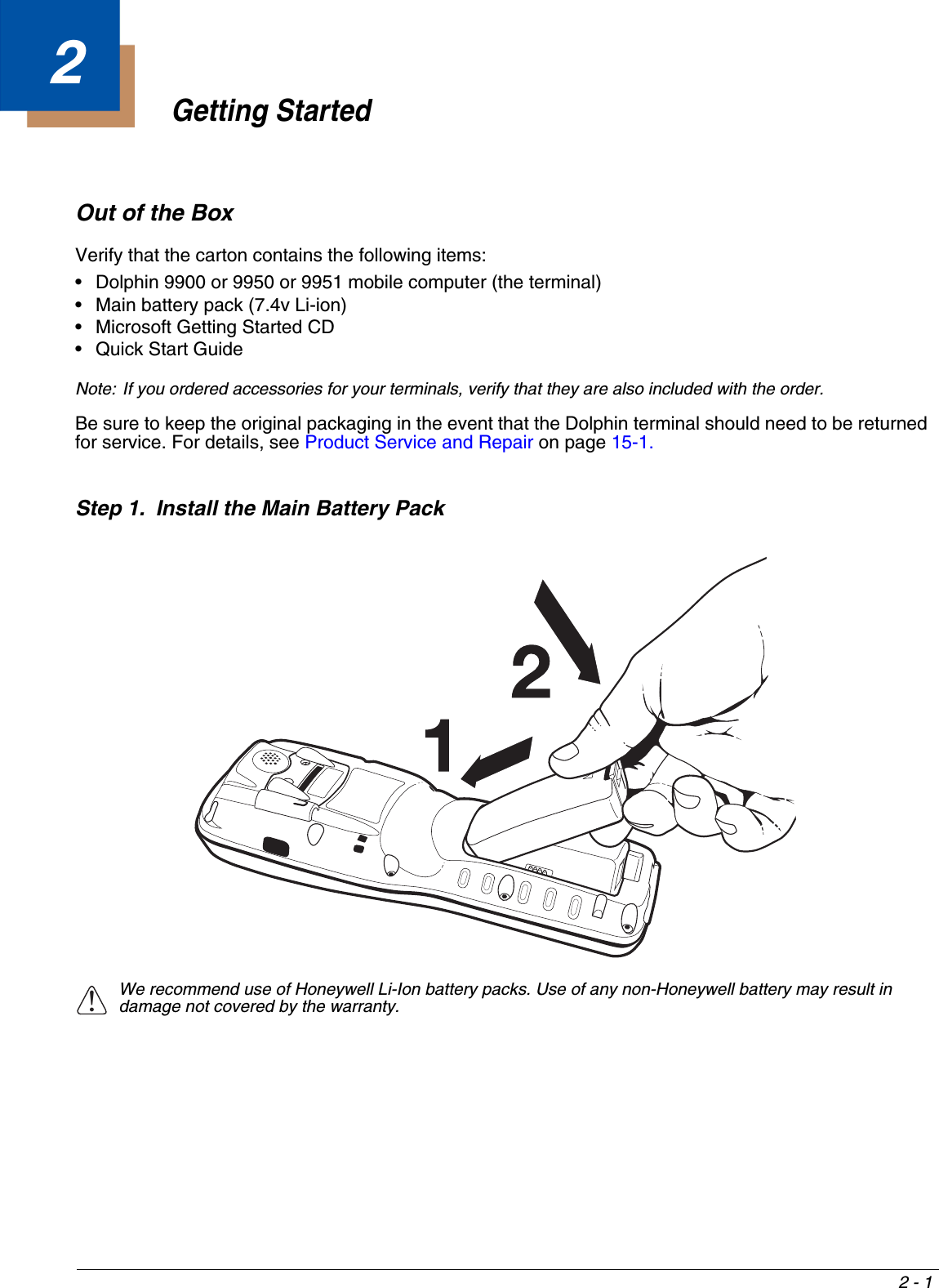
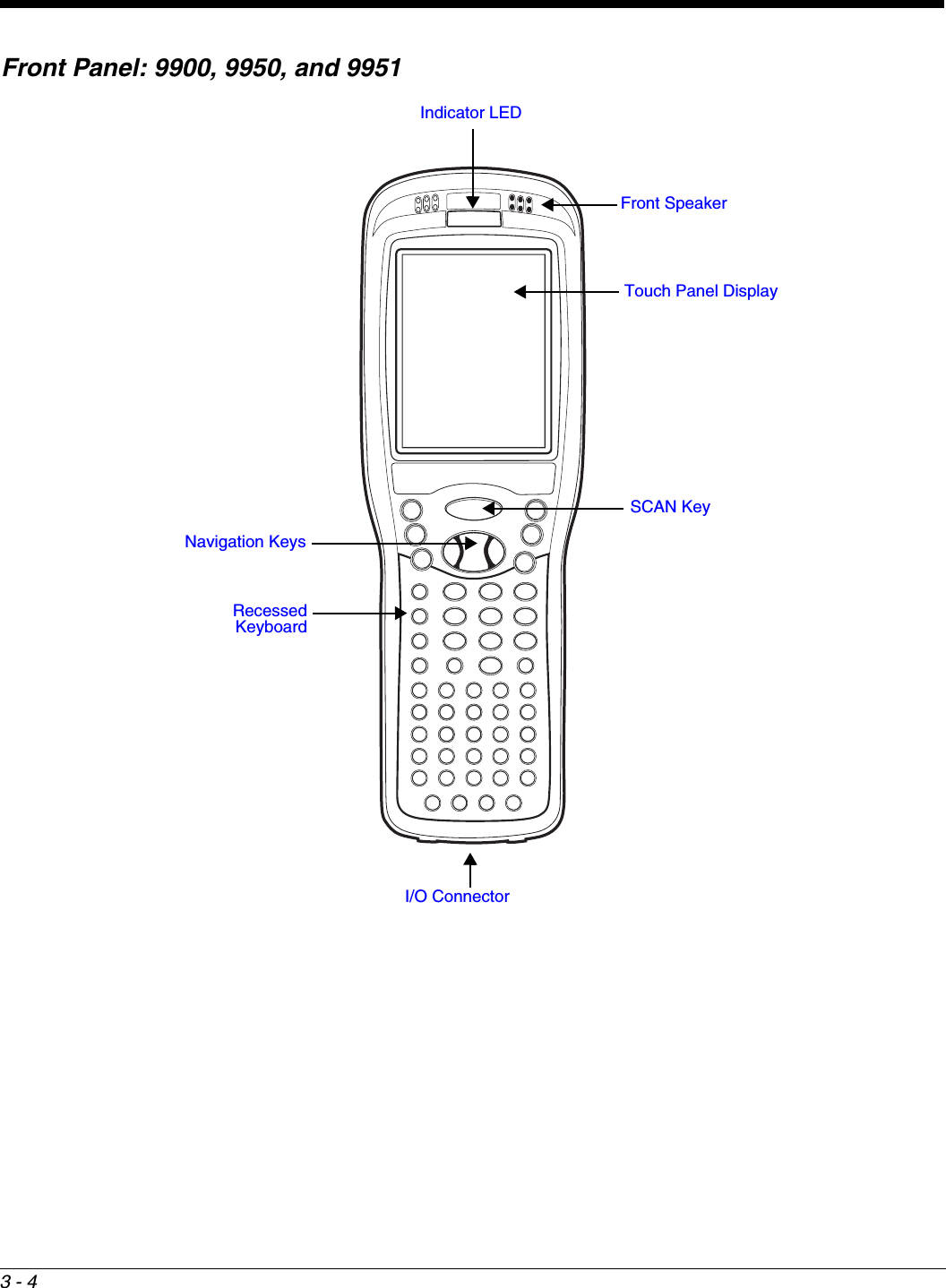
![5 - 1256-Key Keyboard CombinationsKey SHIFT BLUE RED1!2@3#4$5%6^7&8*9(0), (comma) < # (pound). (period) > * (asterisk)A+ (plus) F1B; (semi-colon) F2C[ (left bracket) F3D] (right bracket) F4E" (quotes) F5F- (minus) F6G: (colon) F7H‘ (apostrophe) F8I? (question mark) F9J` (accent) F10K@F11L/ (forward slash) F12M= (equal sign) F13N~ (tilde) F14OF15P_ (underscore) F16Q\ (backslash) F17](https://usermanual.wiki/Honeywell/9900B0P/User-Guide-1436905-Page-56.png)