Honeywell 99EXLF 99EX mobile computer User Manual 2
Honeywell International Inc 99EX mobile computer Users Manual 2
Contents
- 1. Users Manual 1
- 2. Users Manual 2
Users Manual 2
9 - 6
Volume Control
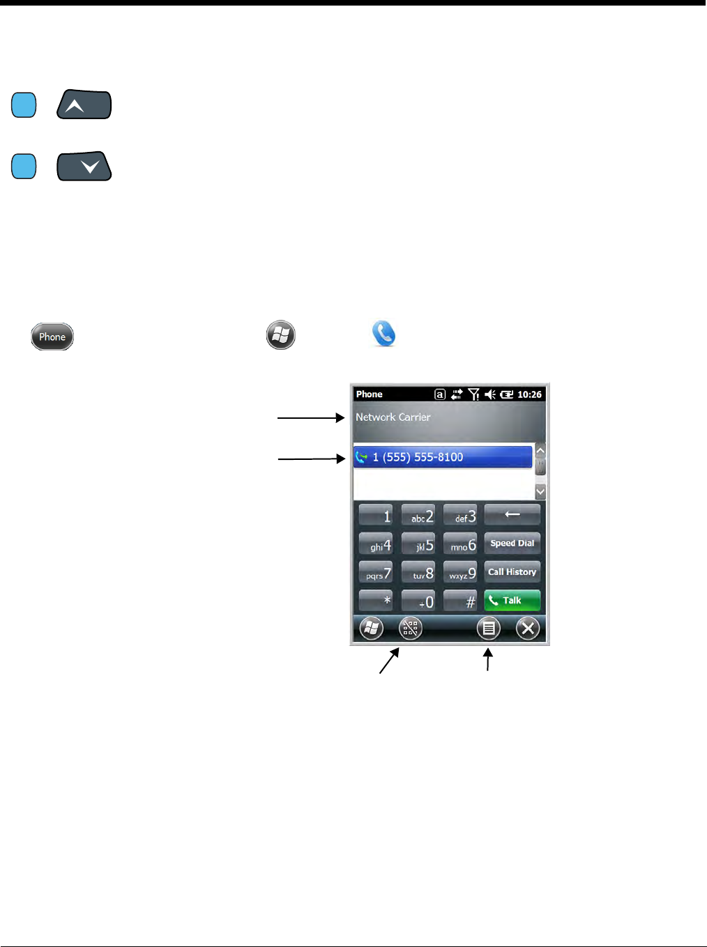
Accessing the Dialer Window
Note: The WWAN radio must be active for voice communication, see Enabling the WWAN Radio on page 9-5.
Tap on the Home screen or tap > Phone to open the Phone dialer.
Dialing
Once the dialer window is open, you can dial out two ways:
• Tap the buttons on the dialer window.
• Use the physical keyboard (when the keyboard is in numeric mode).
&
&
Use the Dolphin keyboard to adjust the volume.
To raise the volume, press the Blue modifier key + up arrow.
To lower the volume, press the Blue modifier key + down arrow.
Or
Press the up or down arrow on the Volume Control button on the right side of the
device to adjust the volume of the active speaker, see Volume Control Button on
page 3-10.
Blue
VOL
Blue
PG
Displays the network carrier
from the SIM card.
Displays the most
recent calls.
Toggles the touch screen
keypad ON or OFF. Menu
9 - 7
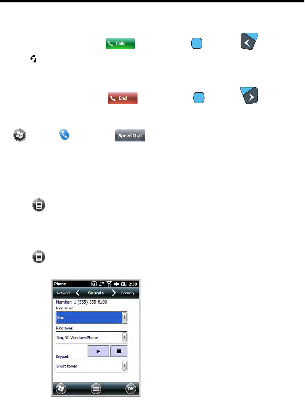
Sending Calls
After the number is dialed, tap Talk or press the Blue + Send key .
Note: The icon indicates that the phone is in use.
Ending Calls
While the phone call is live, tap End or press the Blue + End Key .
Accessing Voice Mail
Tap > Phone > Speed Dial > Voice Mail > Call.
Note: Update the voice mail retrieval number by turning the phone OFF and then ON via the Dolphin Wireless
Manager, see Enabling the WWAN Radio on page 9-5.
View Options
From the view menu, you can modify the display screen to show Calls and Contacts, All Calls or Speed
Dial numbers.
Tap Menu > View.
Setup Options
The Options menu contains four setting widows: Sounds, Security, Services, and Network.
Tap Menu > Options.
Sounds
The Sounds screen enables you to customize the:
• Ring type (e.g., Ring, Increasing ring, Ring once,
Vibrate, Vibrate and ring, Vibrate then ring or None)
• Ring tone
• Keypad tone (e.g., Long, Short, or Off)
SEND
END
9 - 8
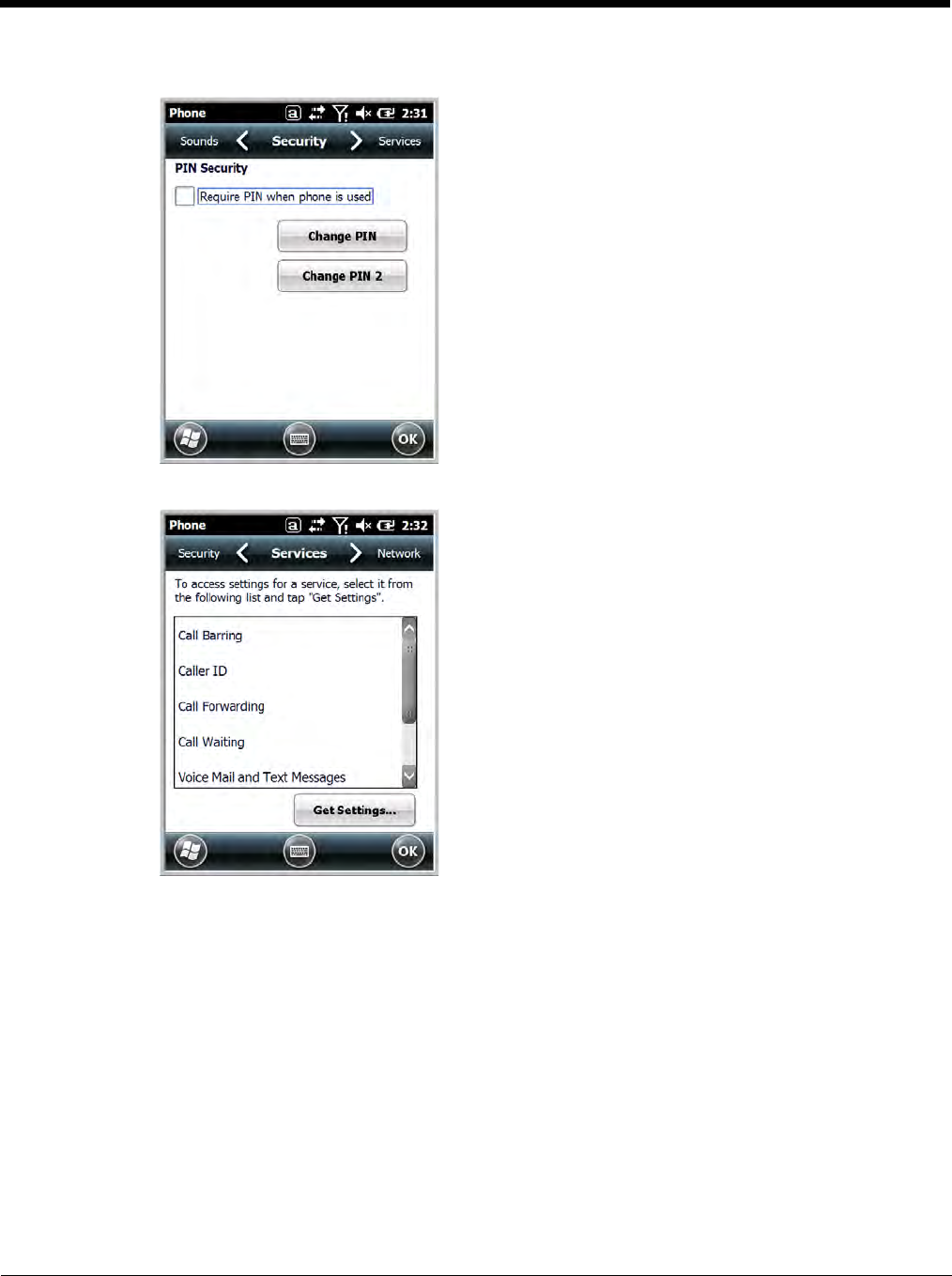
Security
The Security screen provides access to establish or
change your security PIN. Check the box next to,
“Require a PIN when the phone is used” to enable the
PIN security feature.
Services
For each service, the phone reads settings from the
network stored on the SIM card and then displays the
available options from the carrier on the screen. To
customize the settings, select it from the list and tap
“Get Settings”.
9 - 9
Data Communication (GSM/HSPA+ Global Radio Dolphin Models)
You set up data communication via the Connections Manager. The carrier on the SIM card is the ISP.
System Requirements
• The GSM radio must be enabled; see Enabling the WWAN Radio on page 9-5.
• You must have an active SIM card with a DATA plan installed; see SIM Card Installation on page 9-3.
Information Requirements
You must have from the SIM card carrier:
• The APN (access point name).
• The user name and password of the account.
Establishing Data Communication
1. Tap > Settings > Connection > Connections .
2. Under My ISP, tap Add a new modem connection.
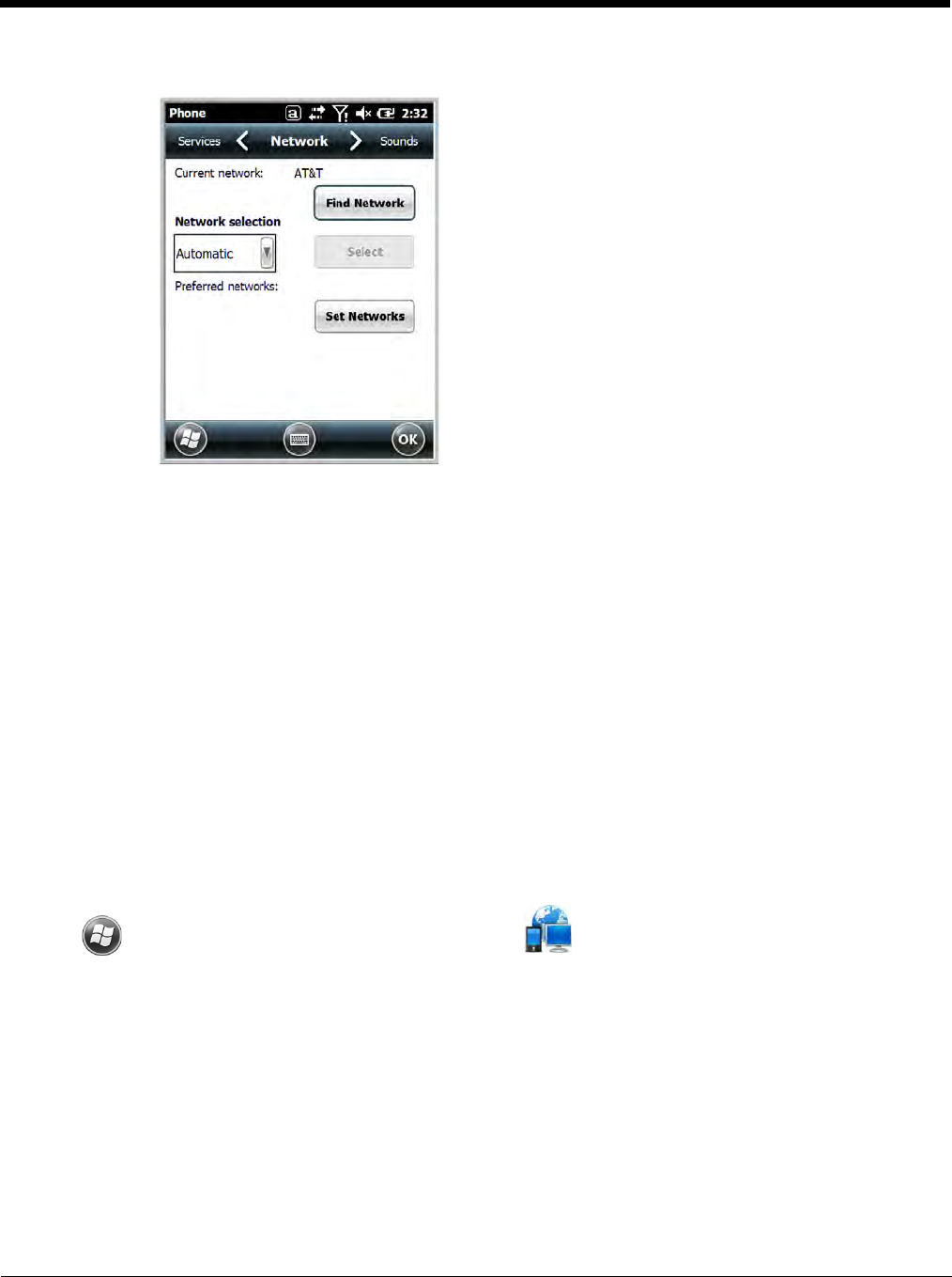
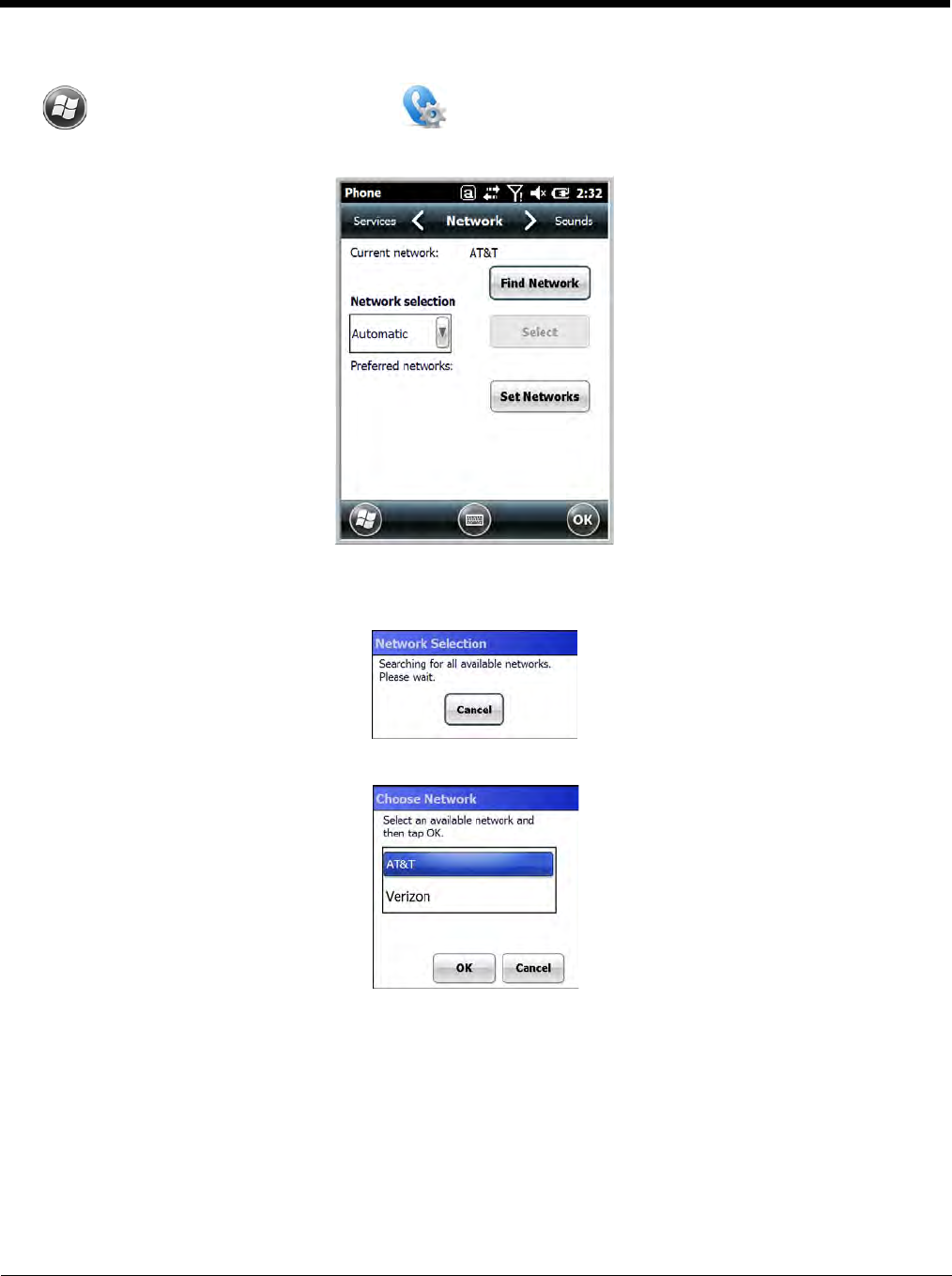
Network
You can find, select, and set your preferred network
order from the Network screen.
9 - 10
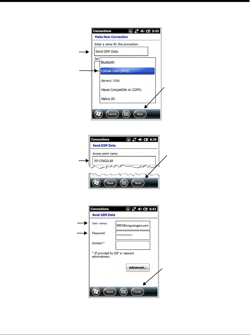
3. Enter a name for the connection. Select Cellular Line (GPRS) as the modem. Tap Next.
4. Enter the Access point name. Tap Next.
5. Enter the user name and password from the account. Tap Finish.
9 - 11
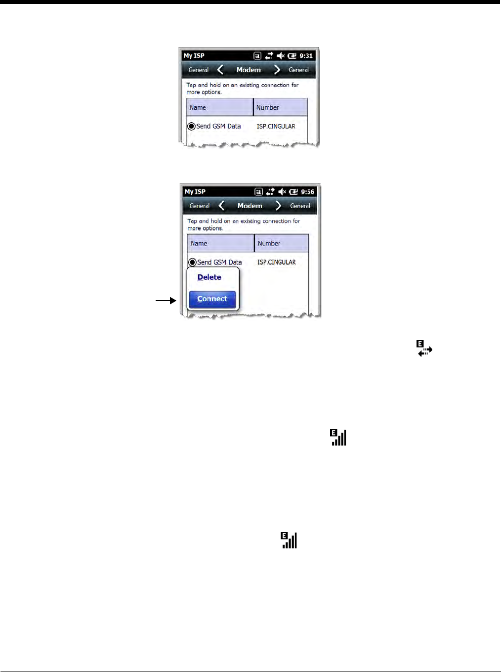
6. The connection you just created should appear in the list on the modem tab.
7. Tap and hold on the connection. Select Connect on the popup menu.
8. The network icon in the Title bar indicates the GSM radio is attempting to connect .
Note: When the device is on a 2G (EDGE/GPRS) network, a data connection failure occurs if the phone is in
use for a voice call while attempting a data connection. Simultaneous voice and data use is only
supported if the device is on a 3G network. In 2G mode, a voice call takes precedence over data
connections. Active data connections are placed in "park" mode automatically and the data is "retrieved"
when the voice call ends.
9. When the connection is complete, the network icon changes to: .
10. You can now send data over GSM.
Ending the Data Connection
By default, the data connection will disconnect after a certain amount of time passes without use.
This period of time is determined by ISP.
To end the data connection manually, tap the network icon in the Title bar and select Disconnect on
the popup bubble.
Manual Network Selection
You can select Automatic or Manual network selection. The Phone defaults to Automatic network selec-
tion.
9 - 12
1. When an active SIM card is inserted in the terminal, tap
> Settings > Personal > Phone > Menu > Options.
2. Select the Network tab.
3. Under Network selection, select Automatic (the default selection) or Manual.
a. If you select Manual, the Phone searches for available networks.
b. The found networks appear.
c. Select a new network and tap OK. The Phone registers on the new network and the Network tab
appears.
d. To switch to another network, tap the now active Select button and the process repeats.
4. To switch back to automatic roaming, select Automatic under Select networks and tap OK.
9 - 13
Data Communication GSM/CDMA Dolphin Models
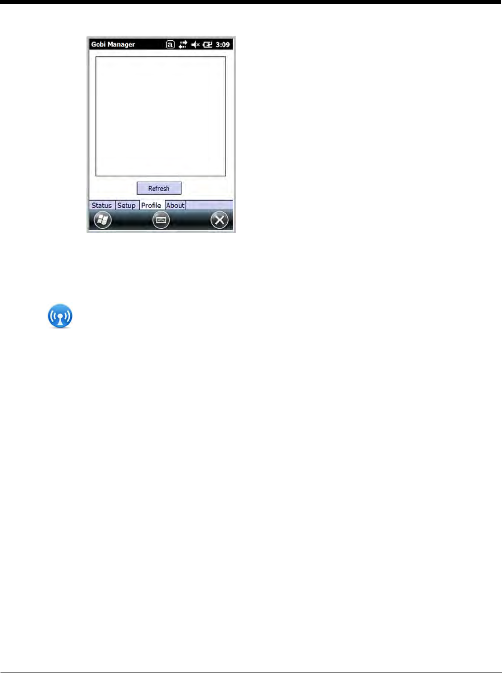
Gobi Manager
The Gobi Manager enables you to see real time status of the radio, setup your Network selection, view
you’re profile and scan for networks. The Gobi Manager contains four tabs: Status, Setup, Profile, and
About.
1. Tap on the Home screen to access the Dolphin Wireless Manager.
2. Tap Menu.
3. Select Gobi Settings.
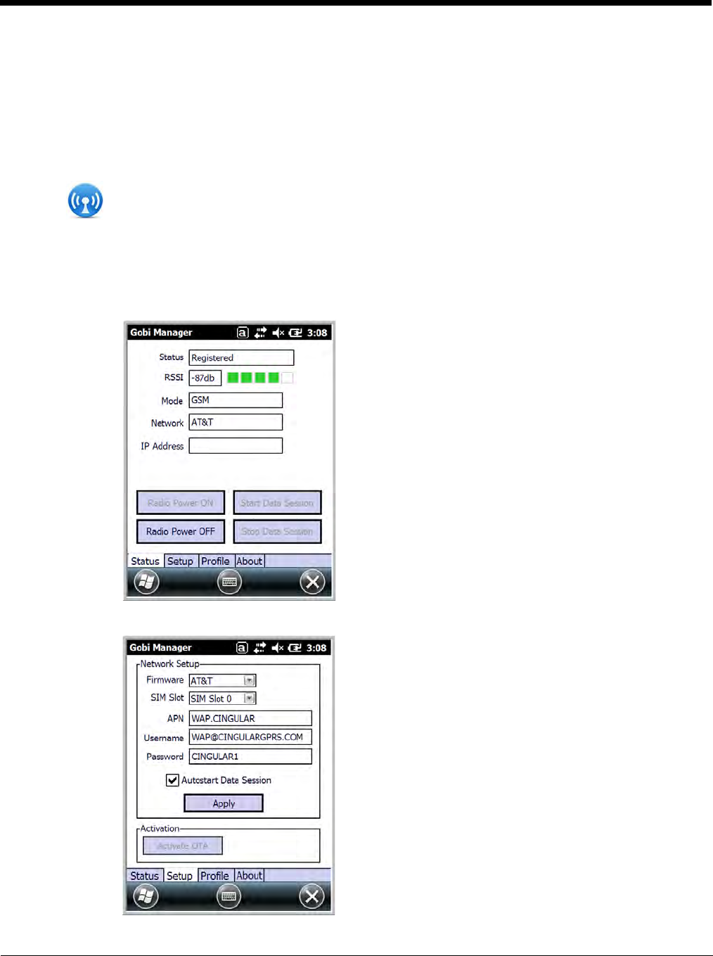
Status Tab The Status tab contains the real time radio status
information including:
• The power status of the radio (e.g., ON or OFF)
• The received signal strength intensity (RSSI)
• The radio mode used (e.g., GSM, UMTS, EVDO
or 1xRTT)
• The network firmware used
• The IP Address assigned
You can also turn the radio ON or OFF and Start or
Stop a data session from the Status tab.
Setup Tab The Setup tab allows you to view and customize the
Network Setup including:
• The Network Firmware (e.g., AT&T, Verizon,
Sprint, or T-Mobile)
• The SIM Slot accessed
• The Access Point Name (APN)
• The User name of the account
• The Password of the account
• Enable or Disable Automatic Data Sessions
• Activate Over the Air (OTA)
9 - 14
Establishing Data Communication
1. Tap on the Home screen to access the Dolphin Wireless Manager.
2. Tap Menu and then select Gobi Settings.
3. From the Setup tab, select the carrier and enter user information (GSM only).
Note: An installed SIM card is required and the SIM slot option must be set to 0.
4. Check the Auto Start Data Session check box to automatically start the data session.
5. Tap the Apply button. The Connection Manager automatically switches to the Status Tab.
6. Tap the Radio Power ON button.
7. When the radio connects to the network, the status changes to “Registered
”
and a signal strength is
displayed.
8. If Auto Start Data Session was checked on the Setup tab, the state automatically changes from
“Registered” to “Data Session Open” and an IP address appears. If Auto Start Data Session was
not selected, then the Data session can be started manually by tapping Start Data Session button
from the Status tab.
Profile Tab The Profile tab allows you to see Radio capability
information and network statistics including:
• Radio Hardware and Software versions
• Radio and SIM identification numbers
• Serving network connection type and state
• Available radio interfaces for the current serving
network
About Tab Displays copyright and version information for the Gobi Connection Manager.
10 - 1
10
Working with the Bluetooth Radio
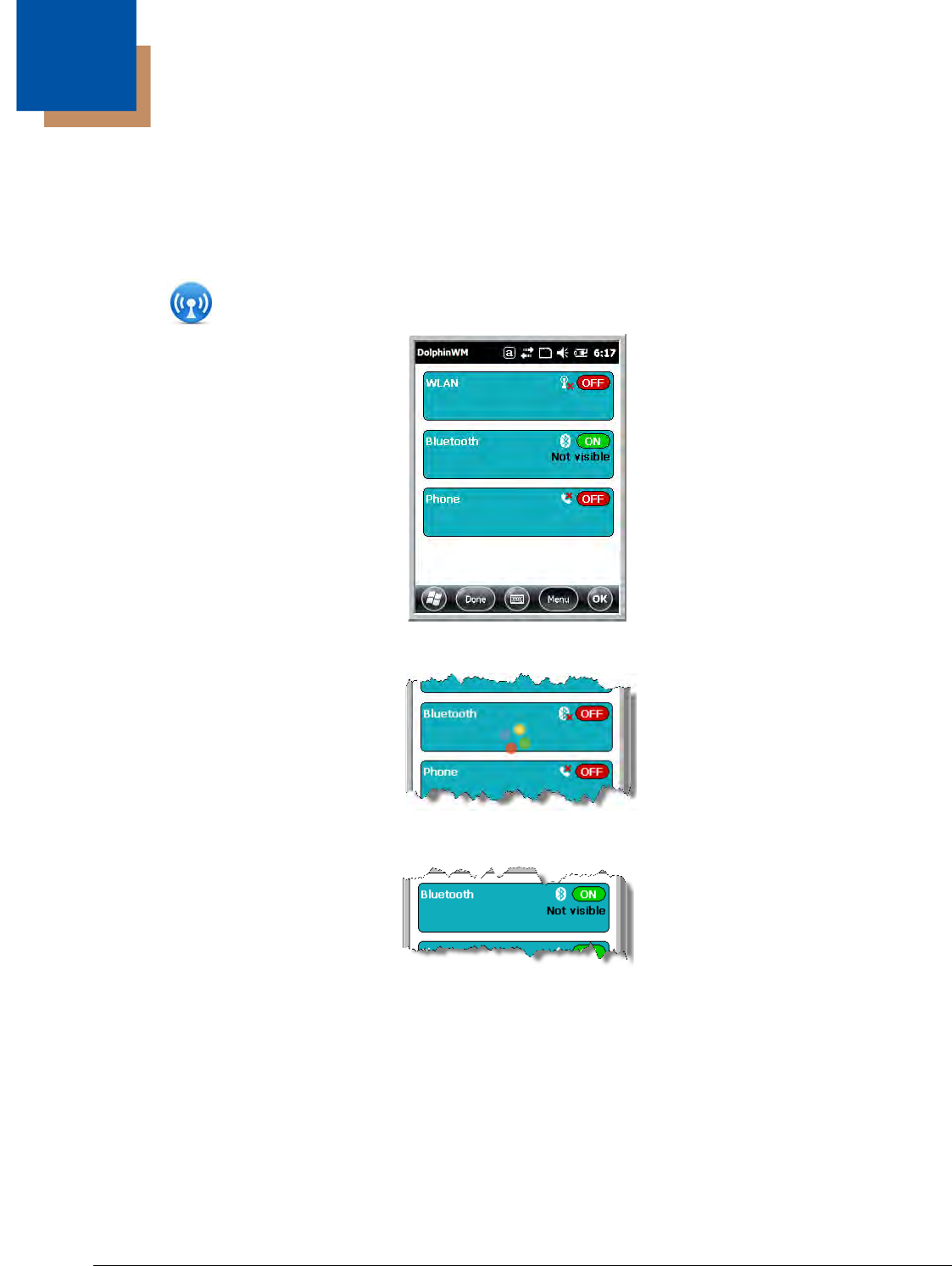
Enabling the Bluetooth Radio
You enable the Bluetooth radio in the Dolphin Wireless Manager (see page 8-6).
1. Tap on the Home screen to access the Dolphin Wireless Manager.
2. Tap anywhere inside the Bluetooth rectangle and Bluetooth begins activating.
3. When the radio is activated (i.e., transmitting a signal), the OFF button changes to ON.
Now, the Bluetooth radio is transmitting a signal. Additional text in the Bluetooth section tells information
about the Bluetooth radio. “Visible” and “Not visible” indicates whether the Bluetooth radio is discover-
able or not discoverable by other Bluetooth devices.
Now, you can connect to other transmitting and discoverable Bluetooth devices (see page 10-2).
To make the terminal discoverable, see page 10-6.
10 - 2
Pairing and Trusted Devices
The terminal does support pairing. Pairing happens during general connection setup. Paired devices are
"trusted" devices. This means that there is unrestricted access to all services (including services that
require authorization and authentication).
A connection can exclude pairing. A device that is connected to the terminal but not paired with it is con-
sidered an untrusted device. Content can still be passed to untrusted devices by requiring authorization
with each attempt (for example, with the initialization of a file exchange). The Beam
File method of file transfer can be used to pass a file as an untrusted device; see Transferring Files on
page 10-5.
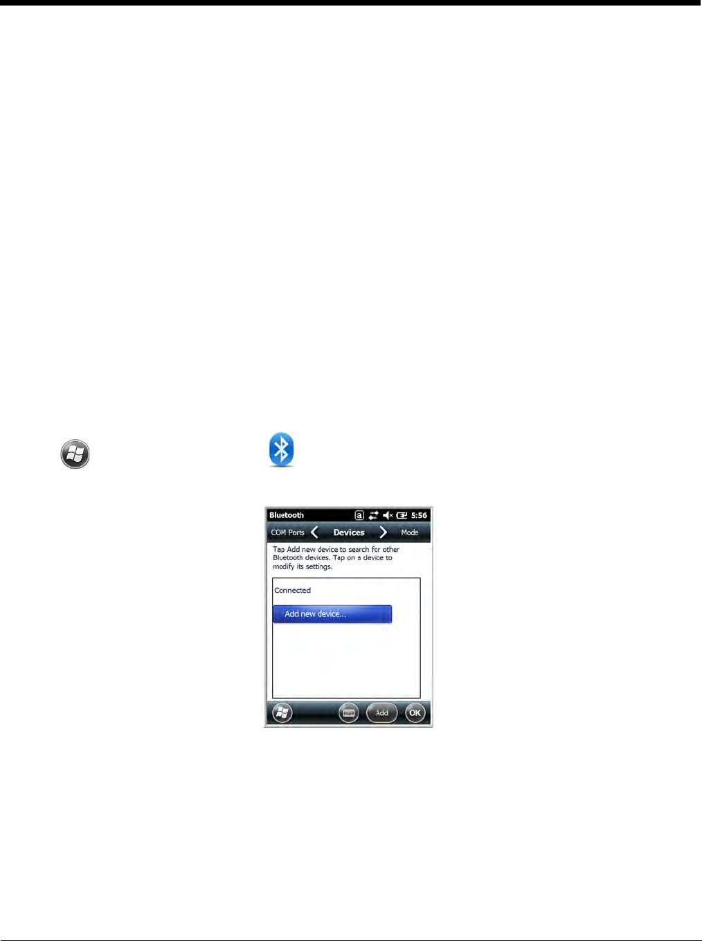
Connecting to Other Bluetooth Devices
To connect to other bluetooth devices, you need to perform a device discovery, select a discovered
device, and then connect to the selected device. Pairing happens as part of the connection process.
1. Make sure the bluetooth device is in range and set to be discoverable by other bluetooth devices.
2. In the Dolphin Wireless Manager, tap Menu > Bluetooth Settings.
OR
Tap > Settings > Bluetooth .
3. Tap Add new device. The terminal begins searching for discoverable Bluetooth devices.
10 - 3
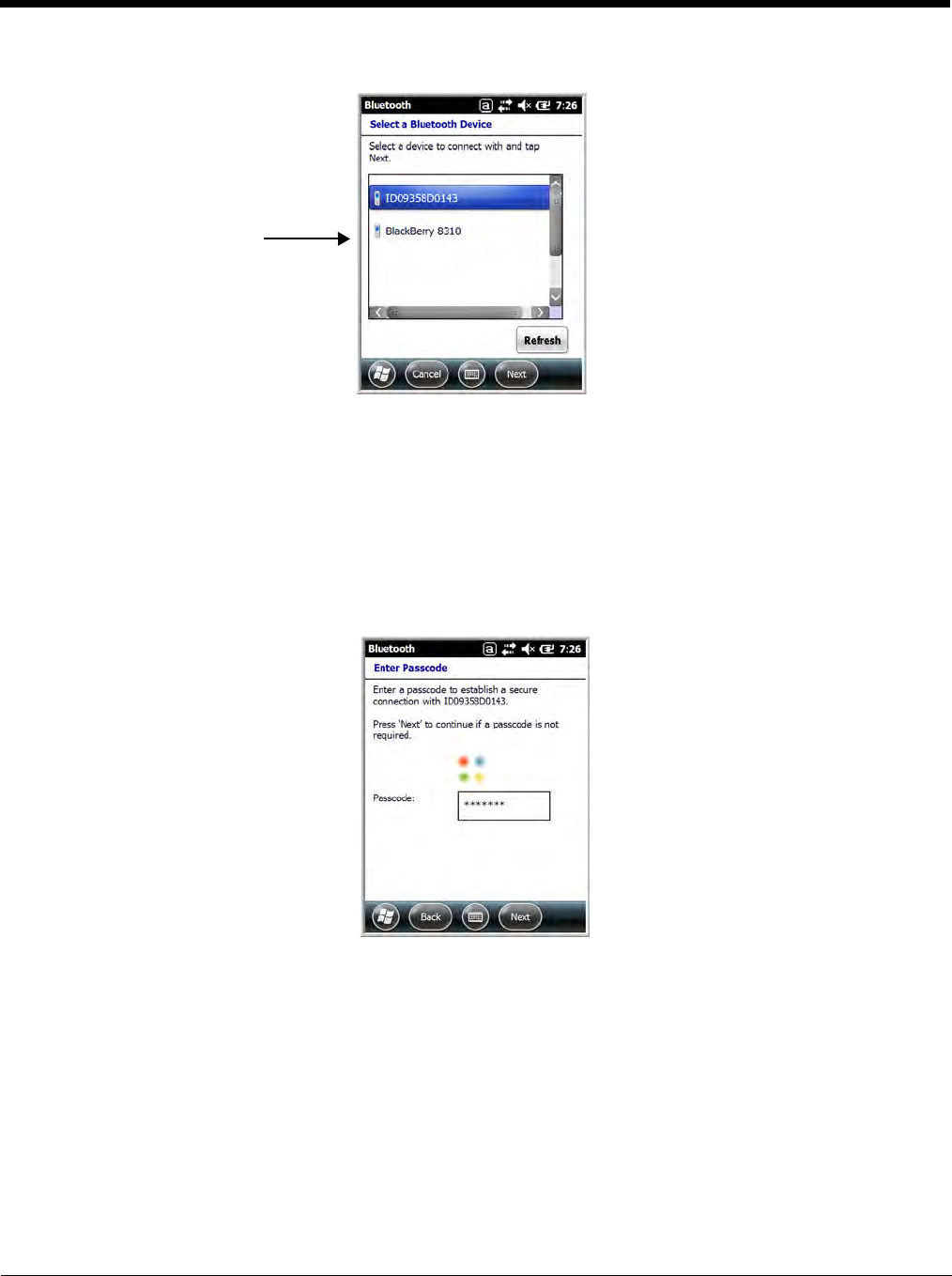
4. Select a device from the list and tap Next.
5. You are prompted to enter a passcode.
• If the device has a specific passcode, enter it in the Passcode field and tap Next.
When attempting to connect to a printer or headset with Bluetooth capabilities, the passcode may
default to either 1111 or 0000. If there is no default, consult the device literature for the number.
• If the device does not have a specific passcode, enter one in the Passcode field and tap Next.
6. The Bluetooth radio tries to connect with the device.
7. If you created a passcode, you will be prompted by the other device to enter the same passcode.
Enter the created passcode to establish a paired connection.
If you entered a device specific passcode, you should not have to do anything on the other device.
The types of devices in the
vicinity of the radio appear in
the list of discovered devices.
10 - 4
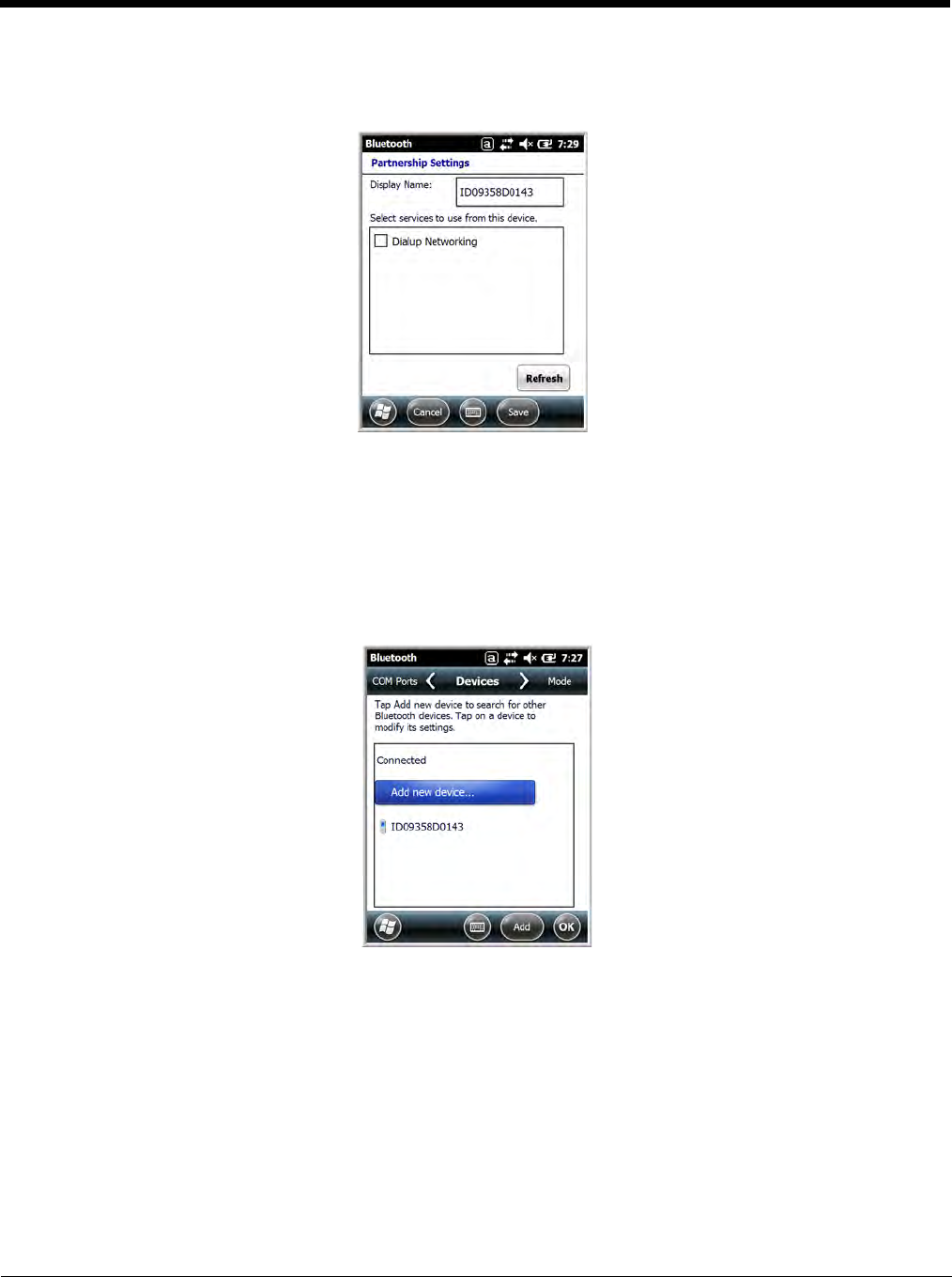
8. When the connection is complete, a list of matching and supported services on the device appears.
Only the services that are mutually supported on both devices appear in the Partnership Settings
window.
9. Select the services you want to use and tap Save.
The services on the new devices have to be selected or the pairing won’t include those services,
even though the devices are paired. If services are not selected, you will be continually re-prompted
for the passcode from the device.
10. The device appears in the list on the main window.
If you are connecting to a printer or headset, complete any additional steps required by the device.
11. After the passcodes have been accepted on both sides, you have a trusted (paired) connection.
10 - 5
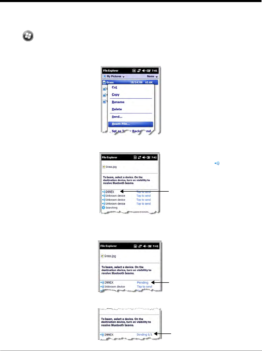
Transferring Files
1. Tap > File Explorer.
2. Navigate to the file you want to transfer.
3. Tap and hold on the file and select Beam File on the popup menu.
4. The Bluetooth radio begins searching for devices.
5. Tap the device to begin sending the selected file.
6. While trying to connect, the selected device reads “Pending”.
7. When the file is being transferred, the selected device reads “Sending”.
When a Bluetooth device is first
found, it appears as an
Unknown device; the icon
indicates that the device is a
Bluetooth device.
As data is retrieved, the device
IDs appear in the list.
10 - 6
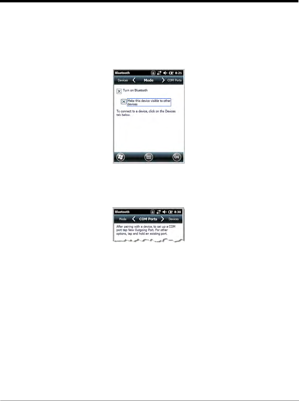
Making the Terminal Discoverable
By default, the Dolphin terminal is not discoverable, which means that the terminal will not be found by
other Bluetooth devices.
To make the terminal discoverable, tap Mode on the Horizontal scroll.
Select Make this device visible to other devices and tap OK.
Selecting COM Ports
You can select COM ports 0-9. For more information, see 99EX and 99GX COM Port Assignment Table
on page 8-13.
11 - 1
11
Working with GPS
Overview
The Dolphin 99EX terminal contains an integrated GPS module that allows location tracking of workers
and vehicles, providing better utilization of field assets. Optional mapping and navigation software pro-
vides turn-by-turn driving directions and location information.
Note: Dolphin 99GX models are not currently offered with GPS capabilities.
Assisted GPS Support
The operating system software does not inhibit nor explicitly support assisted GPS modes, which usually
requires installing a vendor-specific client on the terminal that communicates with the GPS module. This
client would then provide the almanac and/or ephemeris data for warm or hot start modes of operation,
allowing a lower time to first fix (TTFS). The Client must be configured on the terminal, active, and pro-
vide the data to the GPS module through the standard COM port.
Powering the GPS Module
The GPS module powers on automatically when accessed by a software application and powers off
automatically when that software application closes. You cannot manually power on and off the GPS
module.
Communication Ports
There are two ways to access the GPS module: through the actual COM port (COM7) or the GPS Inter-
mediate Driver. The method you use depends on the software application you are using. If the software
application requires the actual COM Port, set the operating system to use COM7. If the software applica-
tion requires the GPS Intermediate Driver, set the operating system to use the GPS Intermediate Driver.
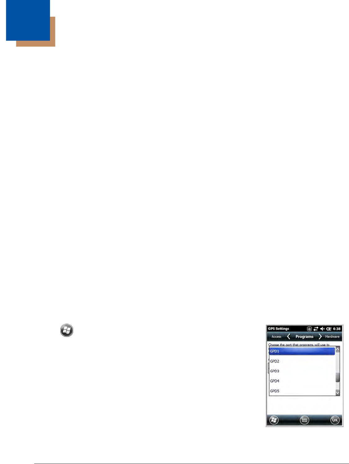
Selecting the Port
1. Tap > Settings > System > External GPS.
2. In the GPS program port: drop-down list, select COM7 or GPD1
(the GPS Intermediate Driver) as required by the application.
Note: The GPS program port and hardware port cannot be the same value.
3. Tap OK to save.
COM7
COM Port 7 can be set to the following baud rates:
•4800
• 9600 (Default baud rate. Recommended for optimal performance.)
• 19200
• 38400

11 - 2
Other baud rates are not possible. The baud rate selected on COM7 is the actual baud rate with which
the GPS communicates.
GPS Intermediate Driver
When the first user of GPD1 opens the port, the GPS Intermediate Driver opens the COM7 port. The
GPS Intermediate Driver allows multiple applications to open GPD1, and the GPS data is broadcast to
all open ports.
When the GPSID driver is in use, the COM7 port is allocated to GPSID as READ|WRITE (COM7 is still
available for access mode of 0).
For more information about Microsoft’s GPS Intermediate Driver, follow this link:
http://msdn.microsoft.com/en-us/library/ms850332.aspx
GPS Demo
The GPS Demo demonstrates the main functionality of the integrated GPS module. The GPS Demo
uses COM7.
To see the GPS Demo, tap > Demos > GPS Demo.

12 - 1
12
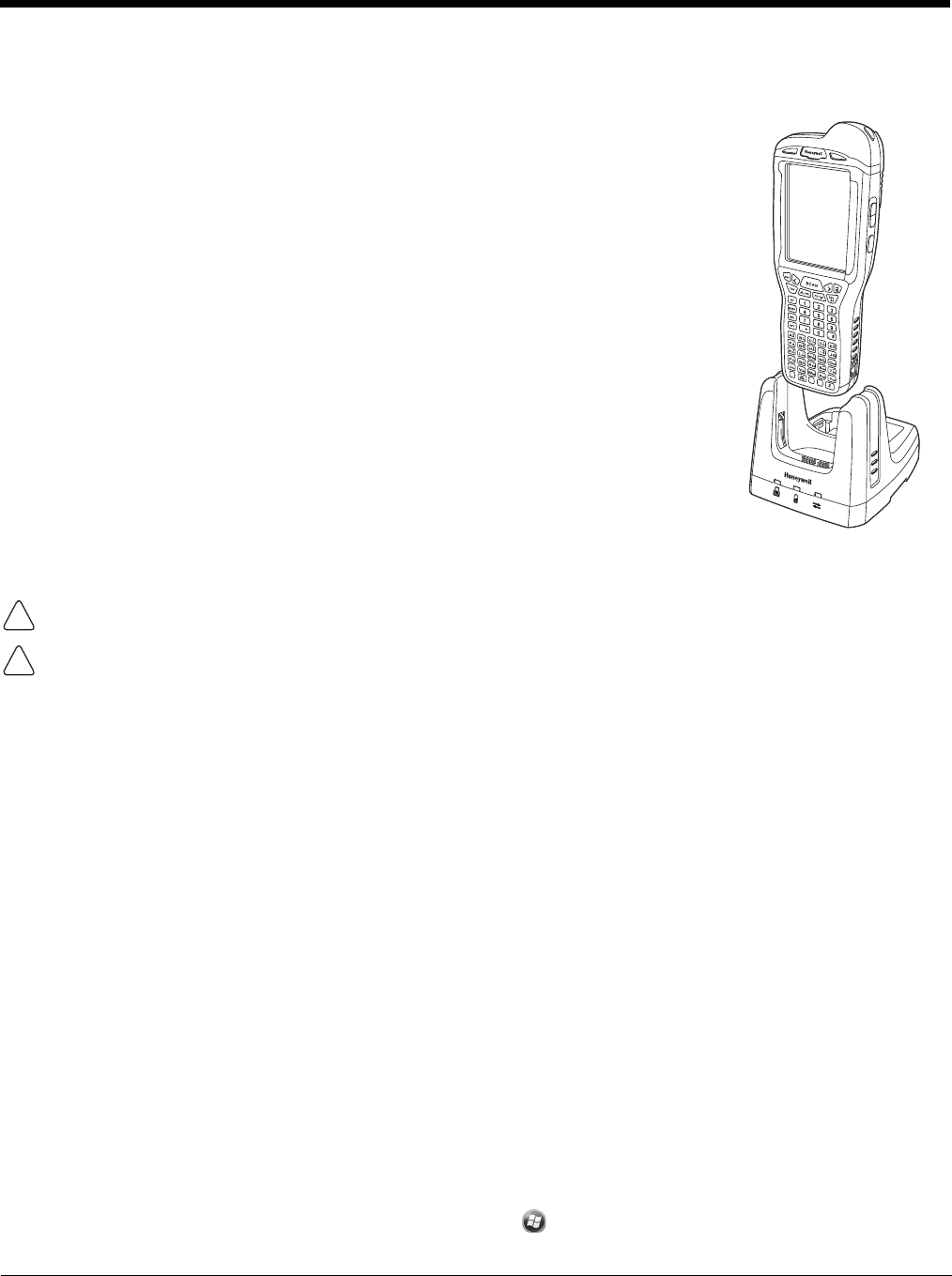
Dolphin 99EX HomeBase Device (Model 99EX-HB)
Overview
As the hub of your Dolphin system, the Dolphin 99EX HomeBase (99EX-HB) charging and communica-
tion cradle supports both RS232 and USB communications, which make it able to interface with the
majority of PC-based enterprise systems.
The 99EX-HB charger is designed for use with battery pack models 99EX-BTSC (standard Li-poly 3.7 V,
11.3 watt hour) and 99EX-BTEC (extended Li-ion 3.7 V, 18.5 watt hour) manufactured for Honeywell
International Inc. and with Dolphin 99EX and 99GX model terminals.
The HomeBase is not designed for use in hazardous locations.
We recommend use of Honeywell peripherals, power cables, and power adapters. Use of any non-Honeywell
peripherals, cables, or power adapters may cause damage not covered by the warranty.
Unpacking the HomeBase
Open the shipping box and inspect the package to see that the following standard items are included:
• One Dolphin HomeBase, model 99EX-HB
• One power supply (see Power on page 12-5)
• One power cord
These items are needed to operate the HomeBase. If any items are missing or anything appears to be
damaged, contact your Customer Account Representative. Keep the original packaging in case you
need to return the HomeBase for service or to store the HomeBase while not in use.
Optional Equipment
A standard RS232 or a standard USB cable is required when using the HomeBase for communication
between the terminal and a host device.
Charge Time
The base completes a full charge of the main battery pack installed in the terminal seated in the terminal
well in 4 hours for the standard battery or 6 hours for the extended battery. The base completes a full
charge of the battery pack in the Auxiliary Battery Well (see page 12-2) in 4 hours for the standard bat-
tery or 6 hours for the extended battery.
Charging Process
The base also provides power to the intelligent battery charging system in all Dolphin terminals that
senses when a full charge has been achieved and switches to a trickle charge to maintain the full
charge.
Communications
Reliable data communications at speeds of up to 115K baud can be transmitted by the base through the
RS232 serial port. Using the Hi-Speed USB port, the data transmission rate goes up to 480 Mbps.
These bases cannot be physically connected to each other - sometimes referred to as “daisy-chained”.
!
!
12 - 2
Convenient Storage
The intelligent battery charging system makes this base a safe and convenient storage receptacle for
your Dolphin terminal.
Capacity
The base holds one terminal and features an auxiliary battery well behind the terminal well that can
charge a battery pack independently of the terminal well. This means that one base can charge two bat-
tery packs: the one installed in the terminal and a spare.
We recommend use of Honeywell Li-ion or Li-poly battery packs. Use of any non-Honeywell battery may result
in damage not covered by the warranty.
We recommend use of Honeywell peripherals, power cables, and power adapters. Use of any non-Honeywell
peripherals, cables, or power adapters may cause damage not covered by the warranty.
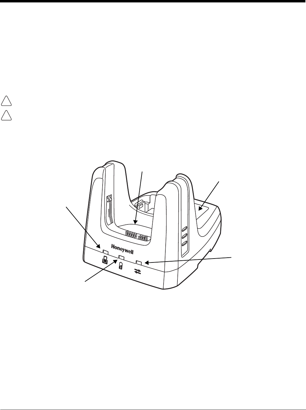
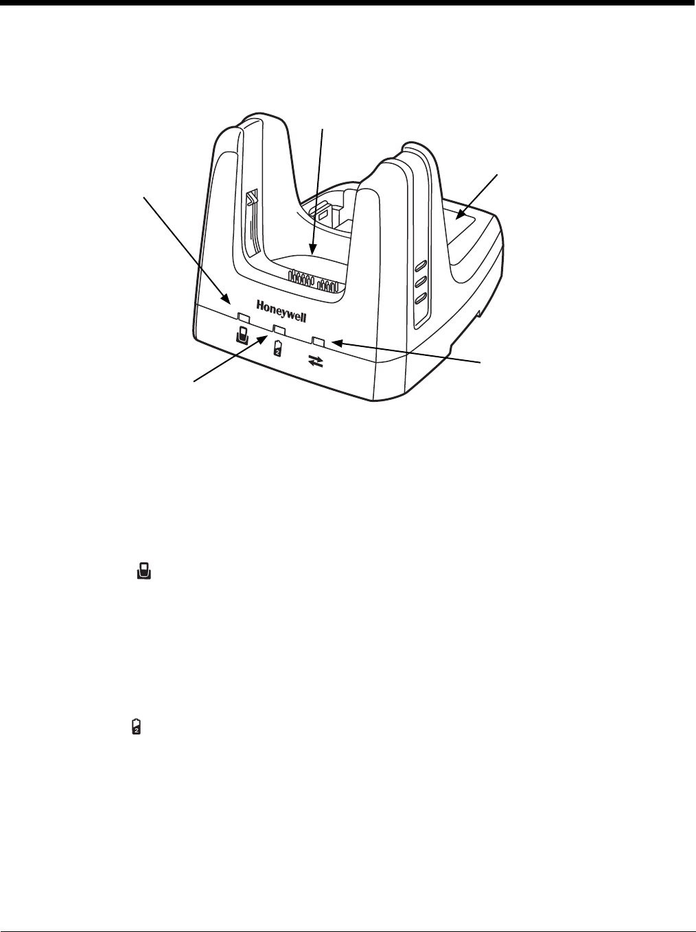
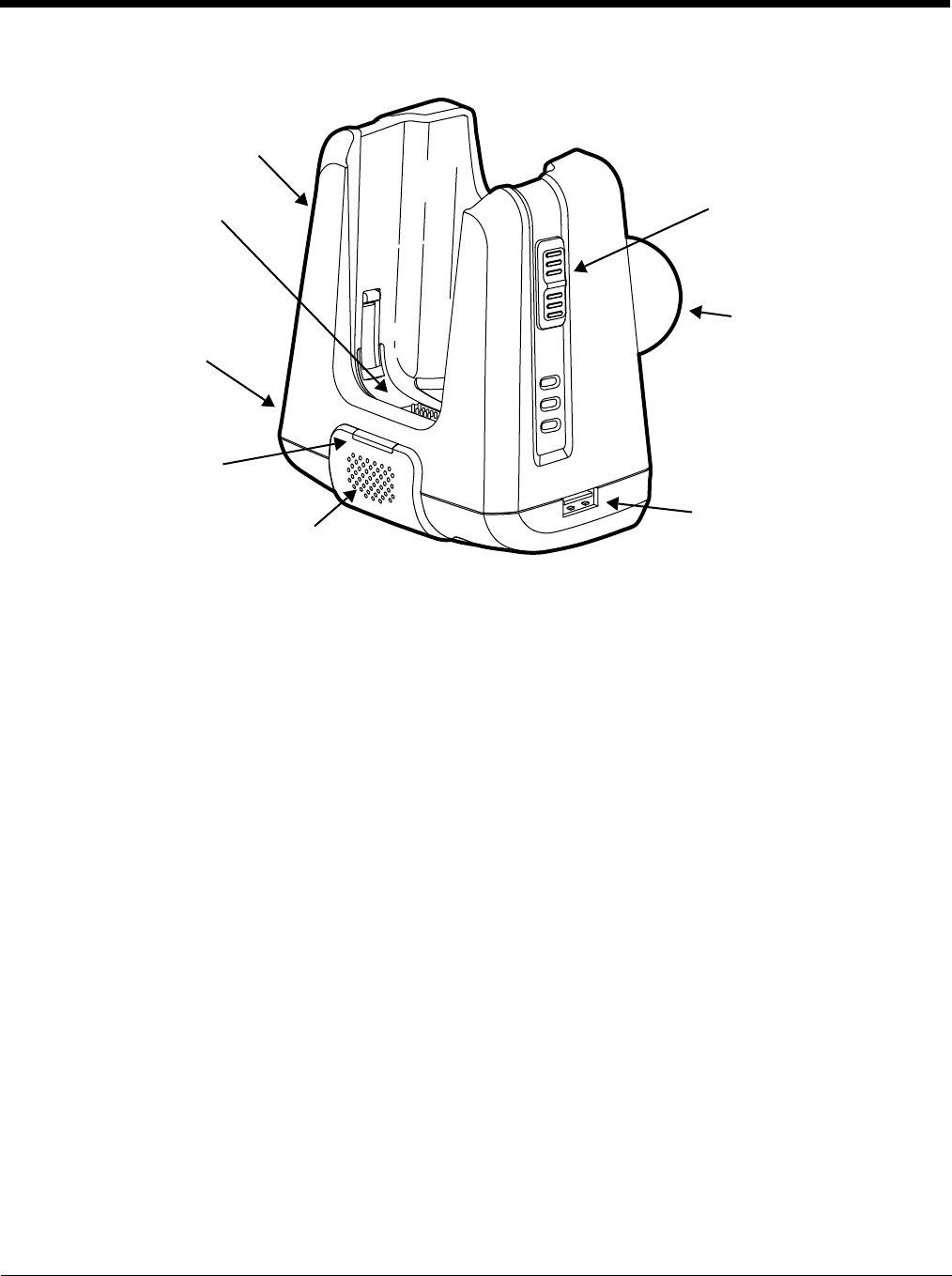
Parts and Functions
Front Panel
Terminal Well
Place the terminal in this well to communicate with a host device, power the terminal, and
charge the installed battery pack. The base completely charges the main battery in a Dolphin
terminal in 4 hours for the standard 3.7V battery or 6 hours for the extended 3.7V battery. If the
host device is a workstation that uses ActiveSync, synchronization begins immediately.
Auxiliary Battery Well
See Auxiliary Battery Well on page 12-4.
!
!
Power/Dock LED
Auxiliary Battery Well
AUX Battery LED
COMM LED
Terminal Well

12 - 3
Power/Dock LED
Indicates if power is supplied to the HomeBase and if a terminal is docked properly in the base.
AUX Battery LED
Indicates status of the battery charging in the auxiliary battery well; see Back Panel on page
12-4.
For information about charging a battery in the auxiliary battery well, see page 12-6.
COMM LED
This is the communication LED. It indicates the status of data transfer between the Dolphin
terminal and the host device. The color of this LED differs if the base is using the serial or USB
port connection.
If using the serial port
If using the USB port
This color means…
Red The HomeBase has power but no terminal is docked.
Green The HomeBase has power and the terminal is properly seated in the base.
This color means…
Orange The auxiliary battery is charging.
Green The auxiliary battery has completed charging and is ready for use.
Red, Flashing The internal temperature of the auxiliary battery is too hot or there is a battery error.
Charge the auxiliary battery in a cooler environment or replace the battery with a
new Honeywell Li-ion or Li-poly battery.
This color means…
Red Serial data is being sent from the host device to the base.
Green Serial data is being sent from the base to the host device.
Orange Serial data is being sent in both directions at the same time.
This color means…
Green A USB Connection is established with the host workstation.
12 - 4
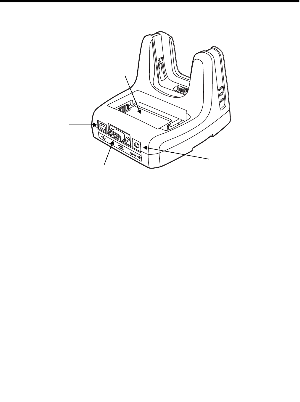
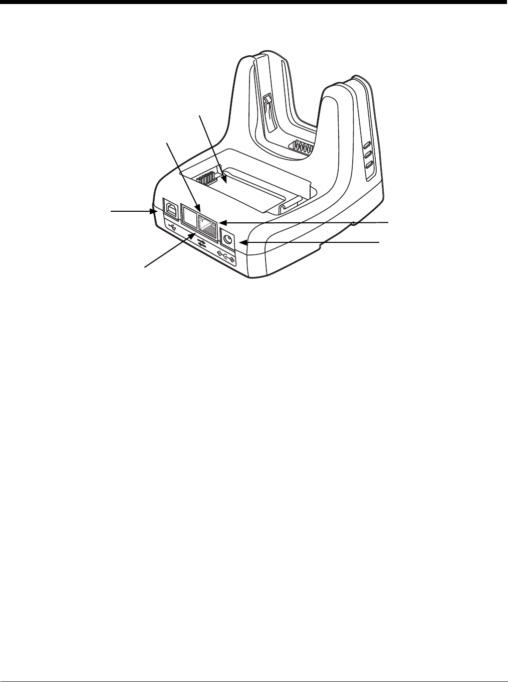
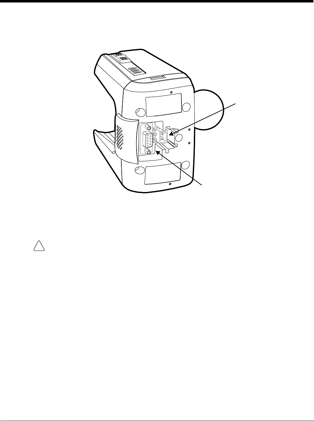
Back Panel
Auxiliary Battery Well
The base enables you to charge an additional battery pack independently of the terminal well
in 4 hours for the standard 3.7V battery or 6 hours for the extended 3.7V battery. This feature
ensures that you can always have a fully-charged battery for your terminal. See Charging a
Spare Battery in the Auxiliary Battery Well on page 12-6.
USB Port
This USB port is USB v2.0 Hi-Speed compliant. Using a USB cable, you can connect the base
to a host device, such as a workstation. USB communication occurs through Microsoft
ActiveSync (v4.5 or higher) or Microsoft Windows Mobile Device Center (WMDC) depending
on the host workstation’s operating system. When the terminal is seated in the terminal well, it
is connected to the host device via the base.
Note: ActiveSync on your Dolphin terminal works with Windows Mobile Device Center on host
workstations running Windows Vista or Windows 7 and with ActiveSync on host workstations
running Windows XP. For detailed information on ActiveSync and WMDC visit Microsoft's
Windows Mobile Web site.
RS232 Port
Use the 9-pin, RS232 cable from Honeywell to connect this port to a peripheral device for
RS232 data communication. For more information, see Serial Connector on page 12-9.
DC Power Jack
Use the power cable from Honeywell that comes with the base to supply power to this power
jack. For more information, see Power on page 12-5.
Auxiliary Battery Well
DC Power Jack
RS232 Port
USB Port
12 - 5
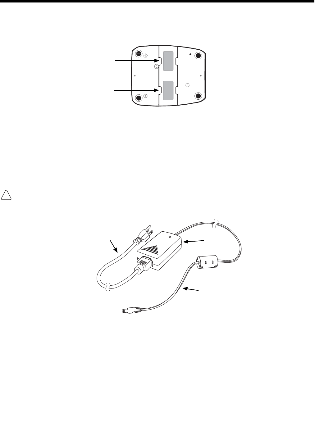
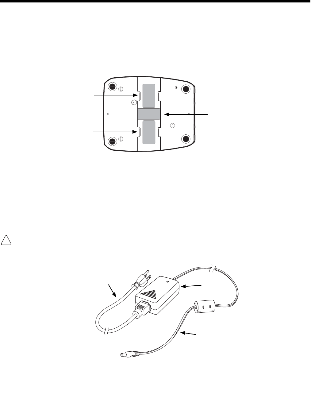
Bottom Panel
For details on how to mount the HomeBase, see Mounting the HomeBase on page 12-9.
Power
The base requires 12 Volts DC input for communications, battery charging, and power output to the ter-
minal; the power adapter included with the base converts the voltage from the AC power source to
12 Volts DC. Use only UL listed power supply, which has been qualified by Honeywell, with output rated
at 12VDC and 3 amps with the device. The operating temperature range is -10° to 50°C (14° to 122°F).
Honeywell recommends that you leave the base connected to its power source at all times, so that it is
always ready to use.
We recommend use of Honeywell peripherals, power cables, and power adapters. Use of any non-Honeywell
peripherals, cables, or power adapters may cause damage not covered by the warranty.
Connecting Power to the HomeBase
1. Plug the A/C power cord into the power adapter.
2. Plug the power cable into the power connector on the back of the HomeBase.
3. Plug the A/C power cord into a grounded power source. The base is now powered. The Power/Dock
LED on the HomeBase illuminates solid red to indicate the HomeBase has power and no terminal is
docked.
Compliance Label
Serial Number Label
!
Power Cable
A/C Power Cord Power
Adapter
12 - 6
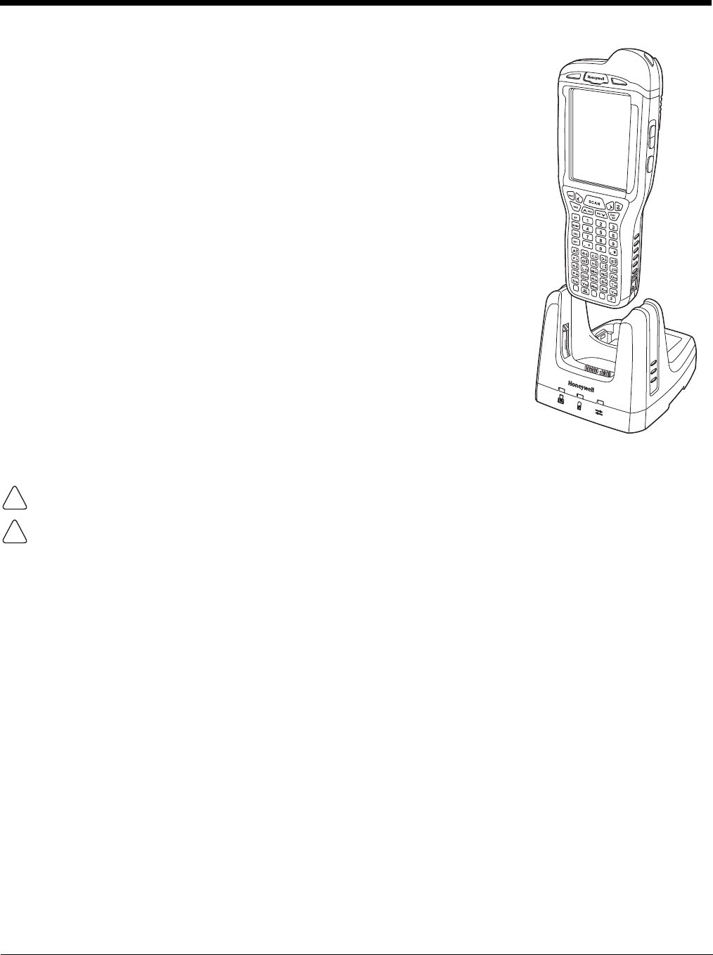
Charging the Main Battery
The base powers the terminal and fully charges its main battery pack in
4 hours for the standard battery or 6 hours for the extended battery. The
terminal contains an intelligent battery charging system that protects the
battery from being damaged by overcharging. The unit senses when a
battery pack is fully charged and automatically switches to a trickle
charge that maintains the battery at full capacity. Therefore, terminals
may be stored in the base without damage to the terminals, battery
packs, or peripherals.
To check battery power, use the Power system setting; see Power on
page 7-16. For more information about Honeywell batteries, see
Batteries on page 3-13.
To Power a Terminal and Charge its Main Battery
1. Install the battery pack in the terminal; see Install the Main Battery
Pack on page 2-1.
2. Verify the base has power. If the Power/Dock LED is not
illuminated, see Connecting Power to the HomeBase on page 12-5.
3. Slide the terminal into the terminal well. The Power/Dock LED
changes to green. The charging begins immediately if required by
the Dolphin terminal.
Ensure all components are dry prior to mating terminals/batteries with peripheral devices. Mating wet
components may cause damage not covered by the warranty.
We recommend use of Honeywell Li-Ion or Li-poly battery packs. Use of any non-Honeywell battery may result
in damage not covered by the warranty.
Charging a Spare Battery in the Auxiliary Battery Well
The auxiliary battery well located on the back of the base charges a spare battery independently of the
terminal well. The Aux Battery LED on the front panel indicates the status of the battery in this well.
Charge time is 4 hours for the standard battery pack or 6 hours for the extended battery pack; see
Auxiliary Battery Well on page 12-4.
1. Insert the battery at an angle so the battery pack contacts and the auxiliary well contacts align.
2. Snap the battery into place with a hinging motion. The Aux Battery LED lights orange.
3. Use the AUX Battery LED to monitor the charging progress. The LED lights green when the auxiliary
battery has completed charging and is ready for use.
Note: If the AUX Battery LED flashes red, the internal temperature of the battery is too hot or there is a battery error.
Charge the auxiliary battery in a cooler environment or replace the battery with a new Honeywell Li-ion or Li-
poly battery.
!
!

12 - 7
Communication
USB
Dolphin terminals support USB communications out of the box. The base also supports USB
communications via the USB port located on the back. The base acts as a USB device by
interfacing the USB signals of the Dolphin terminal to the USB of the host workstation. Using
a standard USB cable, the base’s USB interface allows the Dolphin terminal to communicate
with a workstation.
RS232
The base supports RS232 communications via the RS232 Communications Port located on
the back of the device. This port enables the Dolphin terminal to communicate to a workstation,
modem, or any RS232 device using a standard serial cable and communications software.
Requirements
• A base powered by a power cable and power adapter cable
• For RS232 communications, a serial cable
• For USB communications, a USB cable
• A work station running Windows 98 Second Edition, Windows Me, Windows 2000, Windows NT (4.0
SP6 or higher), Windows XP, Windows Vista, or Windows 7.
• ActiveSync (v4.5 or above) or Widows Mobile Device Center on the workstation
Connecting the Communication Cables
1. Plug in the power supply and connect it to the back of the base.
2. Plug the USB or the RS232 communication cable into the back of the base.
3. Connect the communication cable into the back of the workstation.
4. At this point, the hardware is installed and operating. You may need to reboot your workstation to
complete the installation process.
Establishing Communication
USB or RS232 communication with the terminal is usually auto-detected and configured by ActiveSync
or Windows Mobile Device Center based on the communication cable connected. If you are using a USB
cable to connect to the workstation, the sync software sets up a USB connection. If you are using an
RS232 cable, the sync software sets up an RS232 connection.
For more information, see Serial Connector on page 12-9.
Communicating with the Dolphin Terminal
To initiate communications between the Dolphin terminal and peripheral, complete these steps:
1. Insert the Dolphin terminal into the terminal well of the base.
• The DOCK LED illuminates green. If the DOCK LED does not illuminate, make sure that the terminal is
properly seated. You may need to remove and re-insert the terminal.
• The Dolphin terminal activates; if the power is off, the terminal automatically powers on. If the terminal does
not power on, verify that the Honeywell power supply is properly connected to the cradle and plugged into a
functioning outlet.

12 - 8
• If the base is connected to the workstation, the Dolphin terminal automatically opens ActiveSync or the
Windows Mobile Device Center to establish a connection.
2. The base can now transfer data between the terminal and the host device. If communication does
not occur, check the port connections to ensure that the cradle is correctly configured.
Verifying Communication
You can verify that the USB driver is functioning by watching the COMM LED on the USB base. When
the COMM LED illuminates solid green, the base is communicating with the host device.
Verifying Data Transfer
The COMM LED flashes when data is being transferred via the base. For an RS232 connection, the
COMM LED flashes red and green. For a USB connection, the COMM LED does not flash during data
transfer.
RS232 Communications Cables
Connect the base to the host workstation or other device by plugging an RS232 serial cable into the
RS232 Communications Port on the rear of the base. The wiring of your cable depends on whether the
other device is set up as a Data Communications Equipment (DCE) or Data Terminal Equipment (DTE)
device.
The Communication Port is configured as a DCE device. To communicate with a DCE device, use either
a null modem adapter in line with a standard RS232 cable, or a null-modem serial cable. To communi-
cate with a DTE device such as a workstation, use a standard (or straight-through) RS232 cable.
You can make your own cables by following the pin configuration in the chart that follows. To do so, you
must determine if your host RS232 device is 9-pin or 25-pin, and whether it is configured as a DCE or
DTE device.
RS232 Pin Configuration
Note: This base cannot be daisy-chained.
Note: The input signal names are referenced to the DTE target device (ie. workstation or host computer) in
accordance with the RS232 standard.
Base /Host Port (DCE) IBM AT DB9 (DTE) IBM XT DB25 (DTE) Modem DB25 (DCE)
Pin / Input Signal
2 / (RD) 23 2
3 / (TD) 32 3
5 / (SG) 57 7
4 / (DTR) 4206
6 / (DSR) 66 20
7 / (RTS) 74 5
8 / (CTS) 85 4
12 - 9
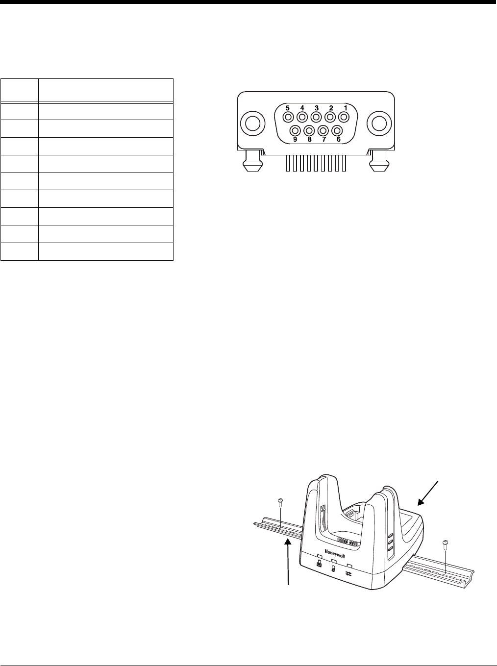
Serial Connector
The following diagram displays the pin diagram of the serial connector of the base.
Note: The signal names are referenced to the terminal. The terminal is a DCE RS232 device. Refer to section,
RS232 Communications Cables and RS232 Pin Configuration for more details. The base is at a right-angle
to the printed circuit board (PCB). The ninth pin has a ring indicator (RI).
Mounting the HomeBase
Set the base on a dry, stable surface, such as a desktop or workbench near an electrical outlet. Be sure
to provide enough workspace with good lighting for the user to view and operate the Dolphin terminal
while it is in the base.
When choosing a mounting location, bear in mind that the location must allow users' easy access to the
Auxiliary Battery Well and the back panel of the HomeBase where the serial port, USB port, and the
power jack are located.
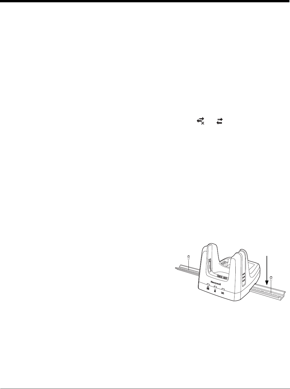
Desk Mounting
The DIN rail slot (7.5 X 35 mm) may be mounted
on the bottom to allow for secure desk attachment
of the unit if desired.
Hardware Required
• 3/16 in. dia x 5/8 in. long pan head screw
• 1/2 in. OD x 7/32 in. ID x 3/64 in. thick washer
• 3/16 in. dia nut
Installing the DIN Rail
1. Slide the DIN rail into the slot along the bot-
tom panel of the base.
2. Then, using the appropriate hardware, secure the DIN rail to the desk or flat surface.
Pin Description
1 Internal Jumper to Pin 6
2TXD
3RXD
4 No Connect
5GND
6DTR
7CTS
8RTS
9RI
Serial and USB port
location (not in view)
DIN Rail (7.5 X 35 mm)

12 - 10

13 - 1
13
Dolphin 99EX eBase Device (Model 99EX-EHB)
Overview
The Ethernet Base (eBase) enables a single Dolphin 99EX or 99GX computer to communicate with a
host device over an Ethernet network.
The 99EX-EHB charger is designed for use with battery pack models 99EX-BTSC (standard Li-poly 3.7
V, 11.3 watt hour) and 99EX-BTEC (extended Li-ion 3.7 V, 18.5 watt hour) manufactured for Honeywell
International Inc. and with Dolphin 99EX and 99GX model terminals.
The eBase is not designed for use in hazardous locations.
We recommend use of Honeywell peripherals, power cables, and power adapters. Use of any non-Honeywell
peripherals, cables, or power adapters may cause damage not covered by the warranty.
Unpacking the eBase
Open the shipping box and inspect the package to see that the following standard items are included:
• One Dolphin eBase Ethernet cradle, model 99EX-EHB
• One power supply (see Power on page 13-5)
• One power cord
You will also need to provide a standard CAT-5 Ethernet network cable. These items are needed to set
up and operate the eBase. If any items are missing or anything appears to be damaged, contact your
Customer Account Representative.
Keep the original packaging in case you need to return the eBase for service or to store the eBase while
not in use.
Charge Time
The base completes a full charge of the main battery pack installed in the terminal seated in the terminal
well in 4 hours for the standard 3.7V battery or 6 hours for the extended 3.7V battery. The base com-
pletes a full charge of the battery pack in the Auxiliary Battery Well (see page 13-2) in 4 hours for the
standard 3.7V battery or 6 hours for the extended 3.7V battery.
Convenient Storage
The intelligent battery charging system makes this base a safe and convenient storage receptacle for
your Dolphin terminal.
Capacity
The base holds one terminal and features an auxiliary battery well behind the terminal well that can
charge a battery pack independently of the terminal well. This means that one base can charge two bat-
tery packs: the one installed in the terminal and a spare.
We recommend use of Honeywell Li-ion or Li-poly battery packs. Use of any non-Honeywell battery may result
in damage not covered by the warranty.
!
!
!
13 - 2
Parts and Functions
Front Panel
Terminal Well
Place the terminal in this well to communicate with a host device, power the terminal, and
charge the installed battery pack. The eBase completely charges the main battery in a Dolphin
terminal in 4 hours for the standard 3.7V battery or 6 hours for the extended 3.7 battery.
Auxiliary Battery Well
See Auxiliary Battery Well on page 13-4.
Power/DOCK LED
Indicates if power is supplied to the eBase and if a terminal is docked properly in the base.
AUX Battery LED
The AUX Battery LED indicates the status of the battery charging in the auxiliary battery well;
see Back Panel on page 13-4.
This color means…
Red The eBase has power but no terminal is docked.
Green The eBase has power and the terminal is properly seated in the base.
This color means…
Orange The auxiliary battery is charging.
Green The auxiliary battery has completed charging and is ready for use.
COMM LED
Power/Dock LED
Terminal Well
AUX Battery LED
Auxiliary Battery Well

13 - 3
COMM LED
The COMM LED indicates the status of data transfer between the Dolphin terminal and the
eBase.
Ethernet Communication
USB Communication
This color means…
Red Flashing The internal temperature of the auxiliary battery is too hot or there is a battery error.
Charge the auxiliary battery in a cooler environment or replace the battery with a
Honeywell Li-ion or Li-poly battery.
When the Dolphin terminal is docked:
This color and status means…
Green Solid A connection has been established between the Dolphin terminal
and the Ethernet.
Green Flashing Data transfer in progress.
When the Dolphin terminal is docked:
This color and status means…
Red Solid A USB connection has been established between the Dolphin
terminal and the host workstation.
13 - 4
Back Panel
Auxiliary Battery Well
The eBase enables you to charge an additional battery pack independently of the terminal well
in 4 hours for the standard 3.7V battery or 6 hours for the extended 3.7V battery. This feature
ensures that you can always have a fully charged battery for your terminal.
USB Port
This USB port is USB v2.0 Hi-Speed compliant. Using a USB cable, you can connect the
eBase to a USB compliant device to facilitate USB communication to and from the terminal.
USB communication occurs through Microsoft ActiveSync (v4.5 or higher) or Microsoft
Windows Mobile Device Center depending on the host workstation’s operating system. When
the terminal is seated in the terminal well, it is connected to the peripheral device via the
eBase.
Note: ActiveSync on your Dolphin terminal works with Windows Mobile Device Center on host
workstations running Windows Vista or Windows 7 and with ActiveSync on host workstations
running Windows XP. For detailed information on ActiveSync and Windows Mobile Device
Center visit Microsoft's Windows Mobile Web site.
RJ45 Ethernet Port
Use a standard CAT-5 Ethernet cable; you can connect the ebase to an Ethernet-compliant
device to facilitate Ethernet communication to and from the terminal.
This color and status means…
Green Flashing Data transfer in progress.
Solid A connection has been established between the Dolphin
terminal and the Ethernet.
Yellow Solid Ethernet is connected at 100T.
Off Ethernet is connected at 10T.
Auxiliary Battery Well
DC Power Jack
RJ45 Ethernet Port
USB Port
Green LED
Yellow LE D
13 - 5
DC Power Jack
Use the power cable from Honeywell that comes with the eBase to supply power to this power
jack. For more information, see Power on page 13-5.
Bottom Panel
For details on how to mount the eBase, see Mounting the eBase on page 13-8.
Power
The terminal requires 12 Volts DC input for communications and battery charging; the power adapter on
the power cable converts the voltage from the power source to 12 Volts DC. Use only UL Listed power
supply, which has been qualified by Honeywell with output rated 12VDC and 3 amps with the device. The
operating temperature range is -10° to 50°C (14° to 122°F).
Honeywell recommends that you leave the eBase connected to its power source at all times, so that it is
always ready to use.
We recommend use of Honeywell peripherals, power cables, and power adapters. Use of any non-Honeywell
peripherals, cables, or power adapters may cause damage not covered by the warranty.
Connecting Power to the eBase
1. Plug the A/C power cord into the power adapter.
2. Plug the power cable into the power connector on the back of the eBase.
3. Plug the A/C power cord into a grounded power source. The Power/Dock LED on the eBase
illuminates solid red to indicate the eBase has power and no terminal is docked.
Compliance Label
Serial Number Label
MAC Address Label
!
Power Cable
A/C Power Cord Power
Adapter
13 - 6
Charging the Main Battery
The eBase provides power to the Dolphin terminal and allows the charging
of the terminal’s main battery. The intelligent battery charging system
incorporated into all Dolphin terminals prevents overcharging, which
means that Dolphin terminals may be stored in the eBase indefinitely with-
out damage to the terminals, battery packs, or the eBase.
To check battery power, use the Power system setting; see Power on page
7-16.
For more information about Honeywell Li-ion batteries, see Batteries on
page 3-13.
To Power a Terminal and Charge its Main Battery
1. Install the battery pack in the terminal; see Install the Main Battery
Pack on page 2-1.
2. Verify the base has power. If the Power/Dock LED is not illuminated,
see Connecting Power to the eBase on page 13-5.
3. Slide the terminal into the terminal well. The Power/Dock LED
changes to green. Battery charging begins immediately if required by
the Dolphin terminal.
Ensure all components are dry prior to mating terminals/batteries with peripheral devices. Mating wet
components may cause damage not covered by the warranty.
We recommend use of Honeywell Li-Ion or Li-poly battery packs. Use of any non-Honeywell battery may result
in damage not covered by the warranty.
Charging a Spare Battery in the Auxiliary Battery Well
The auxiliary battery well located on the back of the base charges a spare battery independently of the
terminal well. The Aux Battery LED on the front panel indicates the status of the battery in this well.
Charge time is 4 hours for the standard battery pack or 6 hours for the extended battery pack; see
Auxiliary Battery Well on page 13-4.
1. Insert the battery at an angle so the battery pack contacts and the auxiliary well contacts align.
2. Snap the battery into place with a hinging motion. The Aux Battery LED lights orange.
3. Use the AUX Battery LED to monitor the charging progress. The LED lights green when the auxiliary
battery has completed charging and is ready for use.
Note: If the AUX Battery LED flashes red, the internal temperature of the battery is too hot or there is a battery
error. Charge the auxiliary battery in a cooler environment or replace the battery with a new Honeywell
Li-ion or Li-poly battery.
Communication
Software Requirements
Before you connect the Dolphin terminal to the eBase, make sure you have the most current software
installed. To check the terminal’s system information, tap > Power Tools > SysInfo.
!
!

13 - 7
• The Kernel version must be 26.01 or later in terminals running Windows Embedded Handheld 6.5
Classic.
• In terminals running Windows Embedded Handheld 6.5 Professional, the kernel version must be 25.01
or later.
Applications on the Dolphin Terminal
Applications running on the Dolphin terminal when it is connected to the eBase should be designed spe-
cifically for a partially connected network. For more details, please refer to the
Best Practices for Partially
Connected Networks
document available at www.honeywellaidc.com.
Establishing Ethernet Communication
Connecting the Dolphin Terminal to the eBase
By default, the Dolphin terminal is configured to obtain IP addresses automatically via DHCP server.
This means that in most cases you would simply plug-and-play the unit.
1. Verify the base has power. If the Power/Dock LED is not illuminated, see Connecting Power to the
eBase on page 13-5.
2. Plug the CAT-5 Ethernet cable into the RJ45 connector on the back of the eBase.
3. Plug the Ethernet cable into the network.
4. Insert the Dolphin into the terminal well. The DOCK LED for the well changes from red to green and
the connection icon on the Dolphin’s title bar changes from to .
Note: Instead of using the default for DHCP assigned IP addresses, the Dolphin terminal can use a statically
assigned IP address. See standard Microsoft Windows Mobile documentation for how to assign a static
IP address to a network adapter. In this case, set a static IP address for the adapter named "SMC95001
USB2.0 FAST Ethernet Drive".
Displaying the eBase and Terminal IP Address
Once the Dolphin terminal has been successfully connected to the eBase, the terminal uses the eBase
IP address. This IP address can be used by any application on the Dolphin terminal.
1. Tap
> Power Tools > Network Utilities > IPConfig
.
2. Change the Adapter to SMC95001.
3. On the Input tab, tap the
Display full configuration
button.
4. The Dolphin terminal retrieves and displays the IP configuration for the entire terminal and eBase.
Locate the
IpAddress
field in the IP configuration list.
Establishing USB Communication
Dolphin terminal’s support USB communication out of the box. The eBase also supports USB communi-
cations using the USB port located on the back panel of the eBase. The eBase acts as a USB device by
interfacing the USB signals of the Dolphin terminal to the USB of the host workstation. Using a standard
USB cable, the ebase’s USB interface allows the Dolphin terminal to communicate with a host worksta-
tion.
x
13 - 8
Setting Up and Connecting the Dolphin Terminal to the eBase
1. Verify the base has power. If the Power/Dock LED is not illuminated, see Connecting Power to the
eBase on page 13-5.
2. Plug the USB communication cable into the USB port on the back of the eBase.
Note: The Dolphin terminal should always be removed from the eBase when connecting or disconnecting the
USB cable.
3. Connect the other end of the USB cable to the host workstation.
4. Insert the Dolphin terminal in the eBase terminal well. The Power/Dock LED changes to green and
the COMM LED illuminates red.
5. The Dolphin terminal activates and automatically opens ActiveSync to establish a connection.
6. The connection icon in the Dolphin’s navigation bar changes from to it indicate a successful
connection. The eBase can now transfer data between the terminal and the host device.
Mounting the eBase
Set the eBase on a dry, stable surface, such as a desktop or workbench near an electrical outlet. Be sure
to provide enough workspace with good lighting for the user to view and operate the Dolphin terminal
while it is in the eBase.
When choosing a location, bear in mind that:
• the mounting location must allow users easy access to the Auxiliary Battery Well, and
• the Ethernet and USB ports as well as the power jack face straight out of the rear panel, and you will
most likely want easy access to them in the future.
Desk Mounting
The DIN rail slot (7.5 X 35 mm) may be mounted on the bottom
to allow for secure desk attachment of the unit if desired.
Hardware Required
• 3/16 in. dia x 5/8 in. long pan head screw
• 1/2 in. OD x 7/32 in. ID x 3/64 in. thick washer
• 3/16 in. dia nut
Installing the DIN Rail
1. Slide the DIN rail slot along the bottom panel.
2. Then, using the appropriate hardware, secure the DIN rail to the desk or flat surface.
x
DIN Rail
(7.5 X 35 mm)

14 - 1
14
Dolphin 99EX Mobile Base Device (Model 99EX-MB)
Overview
The 99EX-MB charging and communication cradle is designed specifically for in-premise and in-transit
data collection applications. It features a flexible mounting bracket and a cigarette lighter adapter to
adapt it to your environment. The 99EX-MB is designed for use with Dolphin 99EX and 99GX model ter-
minals using battery pack model 99EX-BTSC (standard Li-poly 3.7 V, 11.3 watt hour) or 99EX-BTEC
(extended Li-ion 3.7 V, 18.5 watt hour) manufactured for Honeywell International Inc.
The serial connector supports RS232 communication and power out to peripheral devices, such as
handheld scanners. The USB connector supports USB communication and power to peripheral devices
such as a memory stick or printer.
As the hub of your Dolphin mobile data collection system, the base performs three important functions:
charging, communications, and storage.
The Mobile Base is not designed for use in hazardous locations.
Charging
The base completes a full charge of the main battery pack in 4 hours for the standard 3.7V battery pack
or 6 hours for the extended 3.7V battery pack. The base also provides power to the intelligent battery
charging system in all terminals that senses when a full charge has been achieved and switches to a
trickle charge to maintain the full charge.
Communications
The base supports both RS232 and USB communications. Through the RS232 serial port, you can
transmit reliable data communications at speeds of up to 115K baud. By using the Hi-Speed USB (v2.0)
port, the data transmission rate goes up to 480 Mbps.
Convenient Storage
Intelligent battery charging makes the base a safe and convenient storage receptacle for your Dolphin
terminal.
We recommend use of Honeywell Li-Ion or Li- poly battery packs. Use of any non-Honeywell battery may
result in damage not covered by the warranty.
We recommend use of Honeywell peripherals, power cables, and power adapters. Use of any non-Honeywell
peripherals, cables, or power adapters may cause damage not covered by the warranty.
!
!
!
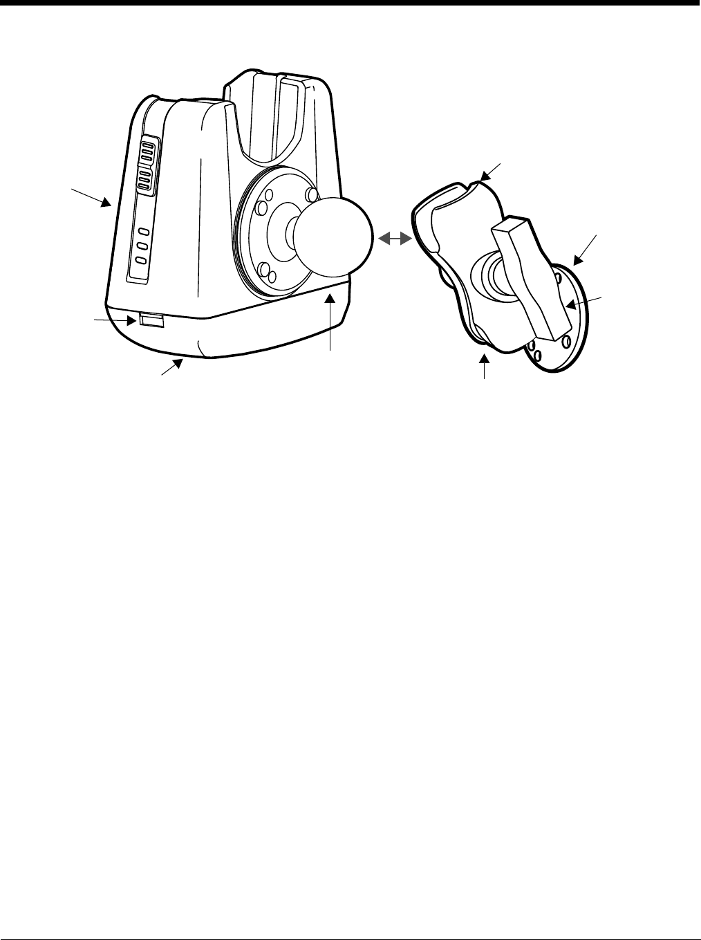
14 - 2
Front Panel
Mounting Bracket
Used to mount the base to a fixed location.
Speaker
Amplifies the Dolphin’s audio signals.
Status LED
Illuminates solid green when the Dolphin terminal is properly seated in the terminal well.
Terminal Locks
The mobile base has a locking switch on the left and right side. Pushing one of the switches
up locks the terminal in the base. To unlock the terminal push either switch down.
Terminal Well
Place the terminal in this well. Once seated, the terminal can communicate with a host device
and its main battery pack begins charging.
USB Communications Port
This USB Port is host Hi-Speed 2.0v compliant. You can connect the base to a peripheral
device, such as a memory stick or to a printer using a USB cable. When the terminal is seated
in the terminal well, it is connected to the peripheral device via the base.
Volume Control Dial
The speaker volume is adjusted via the dial located on the side of the base.
Terminal Well
Status LED
USB
Communications
Port
Volume Control Dial
(not in view)
Speaker
Ball Joint
for Mounting
Bracket
Terminal Lock
Terminal Lock
(not in view)
14 - 3
Bottom Panel
The power supply and RS232 connectors are located on the bottom of the unit.
Power Supply Connector
To run on vehicle power, you can use the 12 VDC cable. The appropriate cable comes with
the kit you ordered. The 12 VDC cable can be used with a cigarette lighter outlet.
Verify that the power source is always within the specified range and observe correct
input voltage polarity. An improper input voltage range or reverse polarity could damage
the power conversion circuitry.
RS232 Communications Port
Use a standard serial cable to connect the unit to a host device via RS232; see Serial
Connector on page 14-8.
RS232 Communications Port
Power Supply
Connector
!
14 - 4
Back Panel and Mounting Brackets
Ball Joints
There are two ball joints: one on the back of the base and one on the mounting bracket. Both
ball joints are inserted into the bracket and secured to mount the base.
Connectors
The power and RS232 connectors are located on the bottom panel.
For more information, see Bottom Panel on page 14-3.
Bracket
The bracket contains the turnscrew and two slots. Ball joints are inserted into each slot and
secured with the turnscrew.
Turnscrew
The turnscrew is located on the top of the bracket. Rotate the turnscrew to secure or loosen
the ball joint slots.
Mounting Bracket
The mounting bracket is what you attach to the mounting surface. It is comprised of a ball joint
and flat disk. The disk contains drill holes you use to secure the base to the mounting surface.
Power supply and
RS232 connectors (not in view)
Base
Turnscrew
Mounting
Bracket
Ball Joint
Bracket
Ball Joint
USB Port

14 - 5
Mounting
The adjustable mounting bracket holds the terminal securely in place and gives the user a variety of
options for mounting the base.
Safety Precautions
Honeywell is not responsible for any damages caused to you, your vehicle, or other individuals due to the
installation of the Dolphin Mobile mount.
Follow these safety precautions when mounting the mobile base:
Never drill into a surface in your vehicle without first consulting a mobile installation professional
experienced with your vehicle type to avoid damaging the vehicle's safety features, gas tank, elec-
trical system or other sensitive vehicle components.
Do not install the Mobile base in an air bag deployment zone. Honeywell assumes no responsibility
of liability for injury or death because of car crashes and/or air bag deployment.
Do not mount the base in a location where it prevents safe operation of the vehicle and/or impedes
the vehicle operator's field of view.
Do not mount the base in a location where the connectors on the bottom panel of the base are not
easily accessible. Be sure to leave enough room for unrestricted cable connections.
The Mobile base is intended for use in an enclosed space protected from the elements. Do not
mount the Mobile base on external vehicle surfaces.
Select a mounting surface that is flat and smooth like the console area in the vehicle located
between the seats.
Installation
Mounting hardware is not included. You must provide the appropriate hardware for your particular appli-
cation and vehicle type. To ensure a safe installation, consult a mobile installation professional
experienced with your vehicle type.
1. Using the bracket as a template, mark the locations for the mount-
ing screws.
2. Drill the appropriate size pilot holes in the mounting surface.
3. Secure the mounting bracket to the mounting surface using the
appropriate screw type for your application and vehicle type.
4. Loosen the turnscrew.
5. Insert the ball joint of the mounting bracket to the back of the bracket.
6. Insert the ball joint on the back of the base into the other side of the bracket.
7. Tighten the turnscrew to secure both ball joints.
!
!!
!
!
!
!

14 - 6
Powering the Dolphin Terminal
When seated in a base that is connected to the appropriate power source, the Dolphin terminal receives
the power to charge its main battery and run its internal circuitry. Keep the base plugged into the power
source so that the Dolphin terminal battery pack stays fully charged.
Note: Honeywell recommends that you leave the base connected to its power source at all times.
The base is powered via the power connector on the bottom panel; see Bottom Panel on page 14-3.
Both the power and serial connectors are straight out, not at an angle. The base requires a 12 VDC
power input.
Charging the Dolphin Terminal
The base supplies charging power to the Dolphin terminal so that the terminal can monitor the charging
of its battery pack. This charging method protects the battery from being damaged by overcharging.
Therefore, the Dolphin terminal may be stored indefinitely in the base without damage to the terminal,
the battery pack, or the base.
Ensure all components are dry prior to mating terminals/batteries with peripheral devices. Mating wet
components may cause damage not covered by the warranty.
1.Insert a battery pack into the terminal.
2. Slide the terminal, imager window up and the LCD visible, into the terminal well until it stops.
3. When the terminal is properly seated, the DOCK LED on the base illuminates solid green. The
terminal begins charging automatically.
Establishing Communication
The RS232 interface allows the terminal to communicate to a workstation, modem, any standard RS232
device using a standard RS232 and communications software.
Requirements
You need the following equipment:
• A Mobile Base device powered by a power adapter cable
• For RS232 communications, a serial cable
• ActiveSync v4.5 or above or Windows Mobile Device Center on the host workstation
• Windows 98 Second Edition, Windows Me, Windows 2000, Windows NT (4.0 SP6 or higher), Windows
XP, Windows Vista or Windows 7 on the host workstation.
Connecting the Communication Cables
Note: You must be using ActiveSync (4.5 or higher) or Windows Mobile Device Center.
1. Plug in the power supply and connect it to the bottom of the base.
2. Plug the RS232 communication cable into the appropriate connector on base.
3. Connect the other end of the communication cable into the back of the workstation.
4. At this point, the hardware is installed and operating.
You may need to reboot your workstation to complete the installation process.
!

14 - 7
Establishing ActiveSync or Windows Mobile Device Center Communication
The Dolphin terminal is usually auto-detected and configured by ActiveSync or Windows Mobile Device
Center based on the communication cable. The synchronization software automatically sets up an
RS232 connection when you are using an RS232 cable.
For more details, see Connecting and Synchronizing the Terminal and Workstation on page 8-8.
RS232 Communication Cables
Connect the base to the host workstation or other device by plugging an RS232 serial cable into the
RS232 Communications Port on the bottom of the base. Plug the other end of the RS232 serial cable
into the correct port on the host RS232 device. The wiring of your cable depends on whether the other
device is set up as a Data Communications Equipment (DCE) or Data Terminal Equipment (DTE)
device.
The Communication Port is configured as a DCE device. To communicate with a DTE device such as a
workstation, use a standard (or straight-through) RS232 cable. To communicate with a DCE device, use
either a null modem adapter in line with a standard RS232 cable, or a null-modem serial cable.
You can make your own cables by following the pin configuration in the chart that follows. To do so, you
must determine if your host RS232 device is 9-pin or 25-pin, and whether it is configured as a DCE or
DTE device.
RS232 Pin Configuration
Note: The input signal names are reference to the DTE target device (i.e., workstation or host computer) in
accordance with the RS232 standard.
Base/Host Port (DCE) IBM AT DB9
(DTE) IBM XT DB25
(DTE) Modem DB25
(DCE)
Pin / Input Signal
2 / (RD) 23 2
3 / (TD) 32 3
5 / (SG) 57 7
4 / (DTR) 420 6
6 / (DSR) 66 20
7 / (RTS) 74 5
8 / (CTS) 85 4
14 - 8
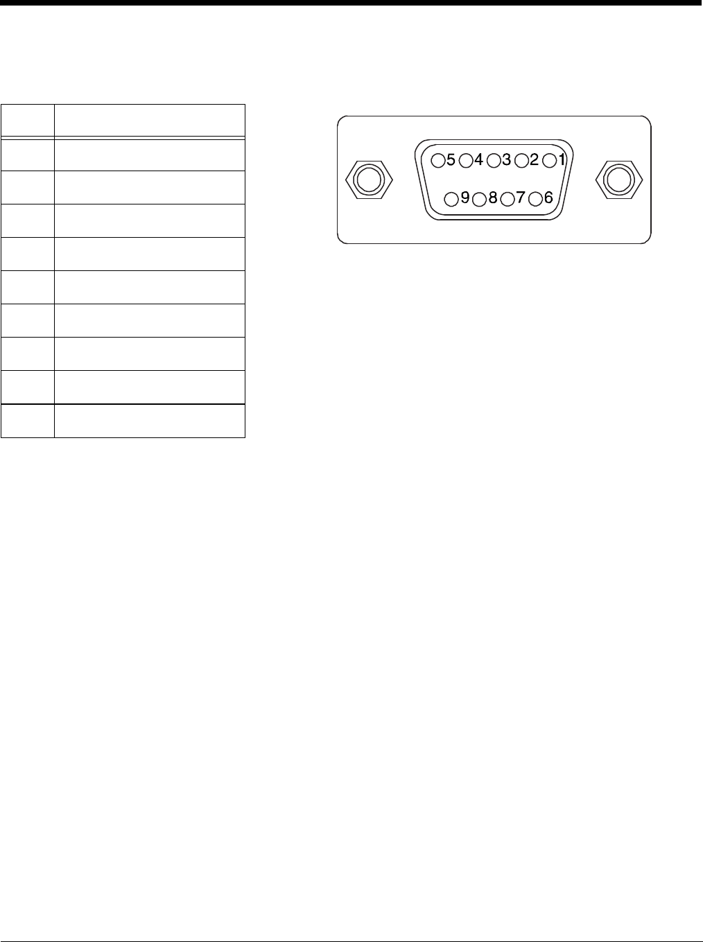
Serial Connector
The following diagram displays the pin diagram of the serial connector of the base.
Note: The signal names are referenced to the terminal. The terminal is a DCE RS232 device. Refer to section,
RS232 Communications Cables and RS232 Pin Configuration for more details.The ninth pin has a ring
indicator (RI).
Pin Description
1 Internal Jumper to Pin 6
2TXD
3RXD
4 No Connect
5GND
6DTR
7CTS
8RTS
9RI

15 - 1
15
Dolphin 99EX ChargeBase Device (Model 99EX-CB)
Overview
The 99EX ChargeBase is a 4-slot charging cradle that can power 4 Dolphin terminals, and charge their
main batteries in 4 hours for the standard battery or 6 hours for the extended battery.
The 99EX-CB charger is designed for use with battery pack models 99EX-BTSC (standard Li-poly 3.7 V,
11.3 watt hour) and 99EX-BTEC (extended Li-ion 3.7 V, 18.5 watt hour) manufactured for Honeywell
International Inc. and with Dolphin 99EX and 99GX model terminals.
The ChargeBase is not designed for use in hazardous locations.
We recommend use of Honeywell peripherals, power cables, and power adapters. Use of any
non-Honeywell peripherals, cables, or power adapters may cause damage not covered by the warranty.
Unpacking the ChargeBase
Open the shipping box and inspect the package to see that the following standard items are included:
• One Dolphin ChargeBase, model 99EX-CB
• One power supply (see Power on page 15-3)
• One power cord
These items are needed to operate the ChargeBase. If any items are missing or anything appears to be
damaged, contact your Customer Account Representative. Keep the original packaging in case you
need to return the ChargeBase for service or to store the ChargeBase while not in use.
Charging
The base supplies power to the intelligent battery charging system in all Dolphin terminals, which senses
when a full charge has been achieved and switches to a trickle charge to maintain the full charge.
As battery packs charge, the charging circuitry follows the two-step charging process (CC-CV) that is
recommended for Li-ion or Li-poly batteries. The process monitors changes in temperature, current, and
voltage. The main battery of each terminal charges in 4 hours for the standard 3.7V battery or 6 hours for
the extended 3.7V battery.
Convenient Storage
Intelligent battery charging makes this base a safe and convenient storage receptacle for your Dolphin
terminal.
Capacity
The base can hold up to 4 Dolphin terminals. Each charging well charges each terminal independently of
the other wells.
We recommend use of Honeywell Li-Ion or Li-poly battery packs. Use of any non-Honeywell battery may result
in damage not covered by the warranty.
!
!
!!
15 - 2
Parts and Functions
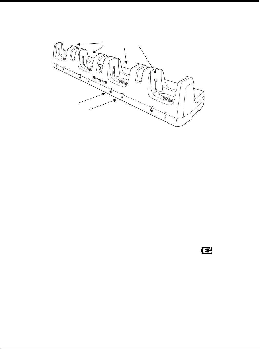
Front Panel
Terminal Wells
The base contains four terminal wells. Each well has its own dedicated Power/Docking LED
and Charging LED indicator.
Power/Dock LEDs
The Power/Dock LED indicates if the ChargeBase has power and if the terminal is properly
seated in the terminal well. Each terminal well has its own dedicated Power/Dock LED.
Charge LEDs
Each terminal well has a dedicated Charge LED located on the front of the base. When a
Dolphin is docked in a terminal well, the Charge LED illuminates green to indicate power is
being applied to the Dolphin. The Battery Icon in the Dolphin window indicates the
terminal is running on external power. If a battery pack is installed, the battery is charging in
the background.
When the Dolphin is removed from the base, the battery icon indicates the charge level of the
main battery pack, see Icons in the Title Bar on page 2-5. For additional information on how to
check the power levels of the main battery pack and the backup battery, while the terminal is
docked, see Checking Battery Power on page 3-16.
For details on how to charge the terminal using the ChargeBase, see Charging the Main
Battery on page 15-4.
This color means…
Red The ChargeBase has power but no terminal is docked.
Green The ChargeBase has power and the terminal is properly seated in the well facilitating
communication between the base and terminal
Power/Dock LED
Charge LED
Terminal Wells
15 - 3
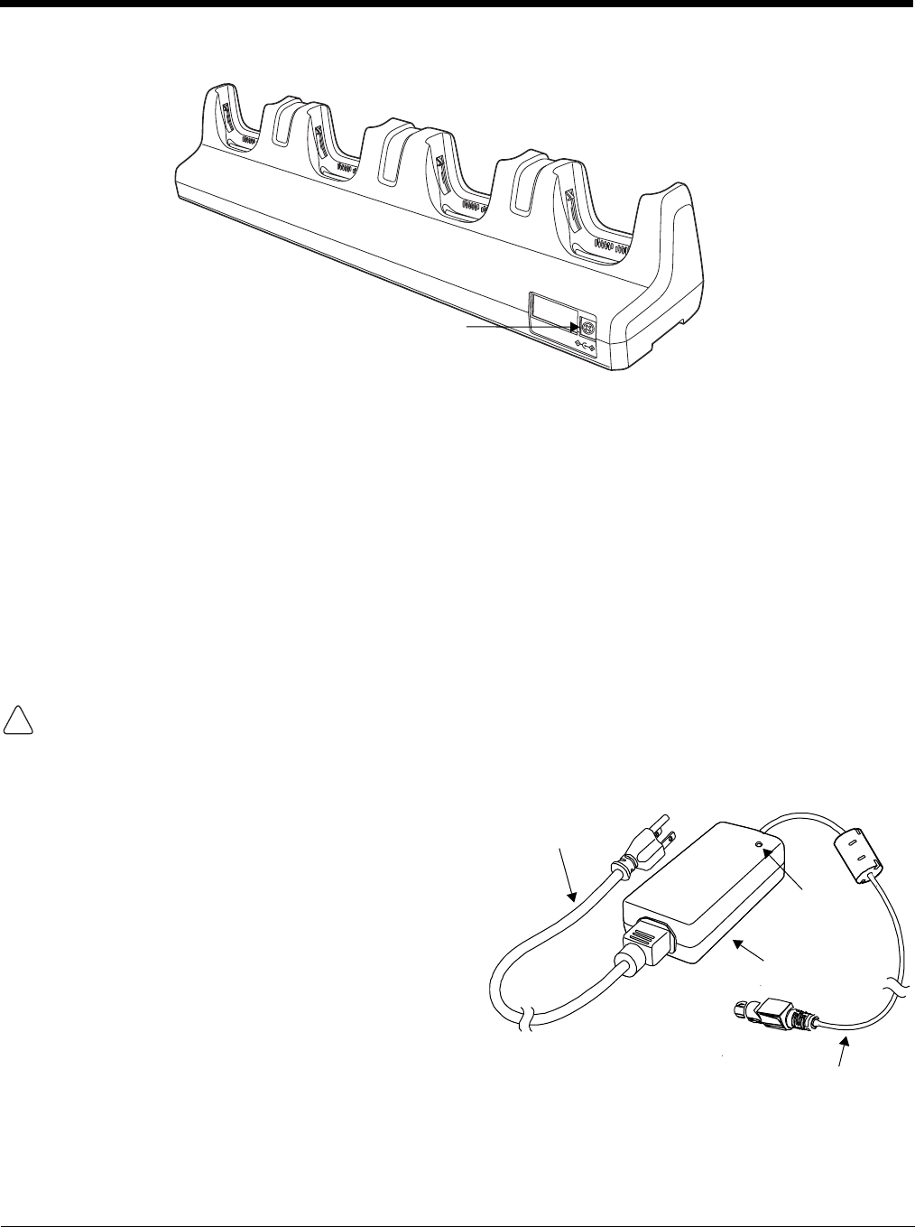
Back Panel
Power Supply Connector
This connector receives input from the power adapter. Plug the power connector cable from
the power adapter into this connector.
Power
The terminal requires 12 Volts DC input for battery charging; the power adapter on the power cable con-
verts the voltage from the power source to 12 volts DC. Use only UL Listed power supply, which has
been qualified by Honeywell with output rated 12VDC and 8.5 amps with the device. The operating tem-
perature range is -10° to 50°C (14° to 122°F).
Honeywell recommends that you leave the ChargeBase connected to its power source at all times, so
that it is always ready to use.
We recommend use of Honeywell peripherals, power cables, and power adapters. Use of any non-Honeywell
peripherals, cables, or power adapters may cause damage not covered by the warranty.
Connecting Power to the ChargeBase
1. Plug the A/C power cord into the power adapter.
2. Plug the power connector cable into the power
connector on the back panel of the ChargeBase.
3. Plug the A/C power cord into a standard wall
outlet. The LED on the Power Adapter
illuminates to indicate power.
4. All of the Power/Dock LEDs illuminate red to
indicate the base has power. Terminal wells with
properly docked Dolphins indicate power with a
green LED.
5. The base is ready to begin charging terminals.
Power Supply Connector
!
Power Adapter
Power Connector Cable
A/C Power Cord
LED
15 - 4
Charging the Main Battery
The base provides power to the Dolphin terminals and allows charging of
the main batteries in the terminals. The main battery of each terminal
charges in 4 hours for the standard 3.7V battery or 6 hours for the
extended 3.7V battery. The intelligent battery charging system incorpo-
rated into all Dolphin terminals prevents overcharging, which means that
Dolphin terminals may be seated in the base indefinitely without damage
to the terminals, battery packs, or the base.
To Power a Terminal and Charge its Main Battery
1. Install the main battery pack in the terminal; see Install the Main Battery Pack on page 2-1.
2. Verify the base has power. If the Power/Dock LEDs are not illuminated, see Connecting Power to
the ChargeBase on page 15-3.
3. Slide the Dolphin terminal into one of the four terminal wells. The the Power/Dock LED for the well
changes to green. Charging begins immediately if required by the Dolphin terminal.
Ensure all components are dry prior to mating terminals/batteries with peripheral devices. Mating wet
components may cause damage not covered by the warranty.
We recommend use of Honeywell Li-Ion or Li-poly battery packs. Use of any non-Honeywell battery may result
in damage not covered by the warranty.
Mounting the ChargeBase
This base should be mounted to a dry, stable surface. When choosing a location, always bear in mind
that:
• The mounting location must allow users easy access to the power connector.
• The base should be oriented so that users can easily see the LEDs.
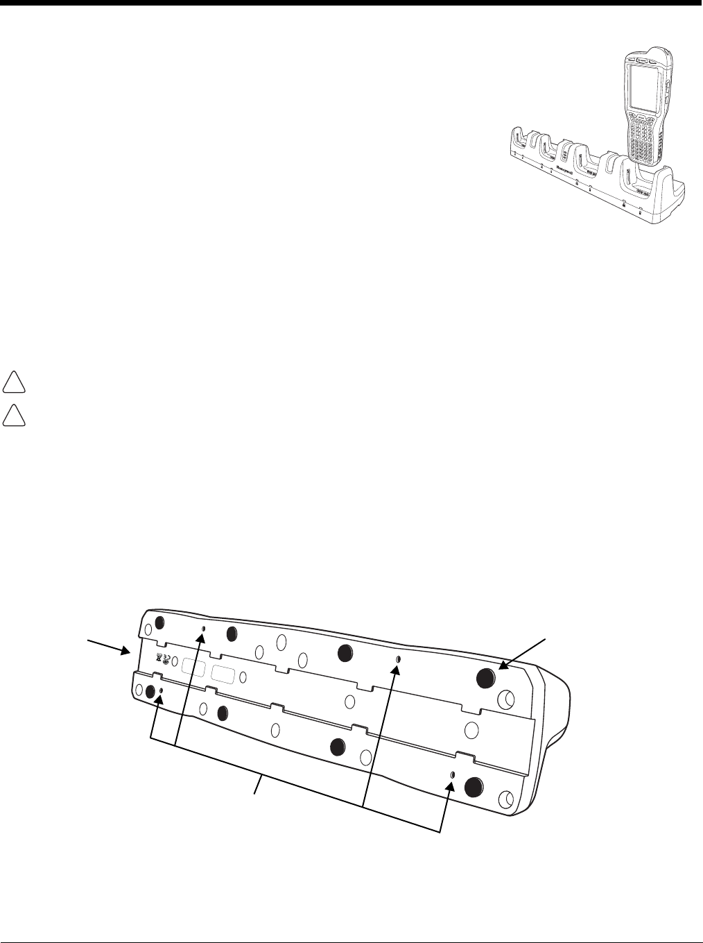
Bottom Panel
Desk Mounting
The DIN Rail (7.5 X 35 mm) slot on the bottom panel enables secure mounting on a horizontal surface.
!
!
DIN Rail Slot Rubber Feet, Qty. 8
Mounting Holes for Wall
Mount Bracket Hardware,
Qty. 4

15 - 5
Hardware Required
• 3/16 in. dia x 5/8 in. long pan head screw
• 1/2 in. OD x 7/32 in. ID x 3/64 in. thick washer
• 3/16 in. dia nut
Installing the DIN Rail
1. Slide the DIN Rail into the DIN Rail slot on the bottom panel of the base.
2. Turn the base and DIN Rail right side up.
3. Then, using the appropriate hardware, secure the DIN Rail to a stable, flat horizontal surface.
Wall Mounting
The optional wall mount bracket enables secure mounting of the base on a vertical surface. The wall
mount bracket can be used in conjunction with the DIN rail but does not require the DIN Rail for use.
Hardware (Provided)
• M3 x 9 mm self-tapping screws, #2 Phillips, Qty. 4
• 3/8 in. x 4 in. round head toggle bolt, 2-5/8 in. usable length, Qty. 4
• 3/8 in. x 2 1/2 in. length Hex Head Lag Screw, Qty. 4
Tools Required
•Drill
• 7/8 in. Drill Bit (for hollow wall installations) or
1/4 in. Drill Bit (for wood stud installation)
• Phillips Screw Driver
DIN Rail (7.5 X 35 mm)
15 - 6
Hollow Wall Installation
1. Drill four pilot holes in the wall using a 7/8 in. drill bit.
2. Slide the bolt through the wall bracket, and thread the toggle nut onto
the bolt.
3. Press the ends of the toggle nut together, and insert the bolt/nut into the
pilot hole until the nut clears inside wall surface. The toggle nut should
spring open preventing the screw from being removed.
4. Repeat steps 2 and 3 for each of the remaining mounting holes.
5. Tighten all four bolts to secure the bracket to the wall.
6. Once the bracket is installed, secure the base to the wall bracket, see
Securing the Base to the Wall Bracket for detailed instructions.
Wood Stud Installation
1. Drill four pilot holes in the wall/wood stud using the 1/4 in. drill bit.
2. Secure the bracket to the wall using the four Hex Head Lag Screws provided.
3. Once the bracket is installed, secure the base to the wall bracket, see Securing the Base to the Wall
Bracket for detailed instructions.
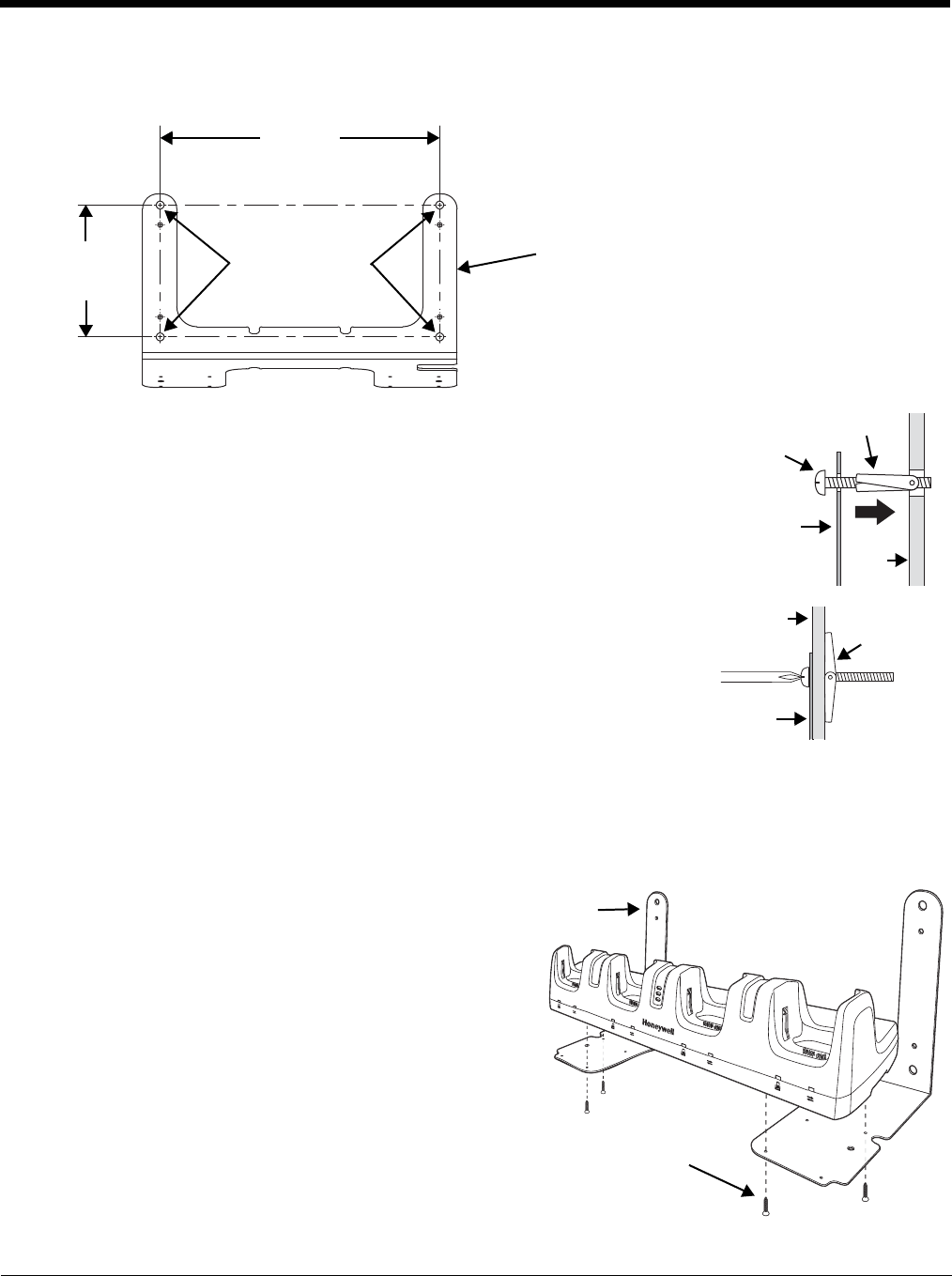
Securing the Base to the Wall Bracket
You can secure the base to the wall bracket by
using the self tapping screws provided or you can
use the optional DIN Rail.
To secure the base using the self tapping screws:
1. Position the base on the wall bracket, as
shown.
2. Secure the base to the bracket using the four
M3 x 9 mm self-tapping screws.
Wall Mount Holes
6.5 in.
[16.5 cm]
13.78 in.
[35 cm]
Wall Mount Bracket
Bolt
Bracket
Wall
Toggle Nut
Open
Toggle Nut
Wall
Bracket
Wall Bracket
M3 x 9 mm Self-tapping
Screws, Qty. 4
15 - 7
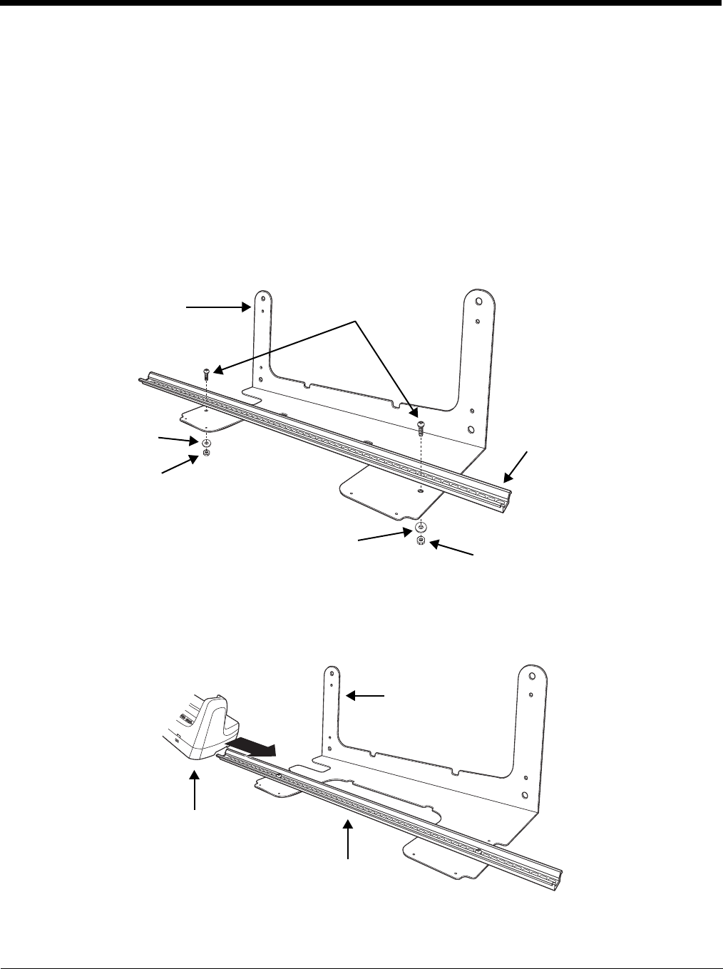
To secure the base using the optional DIN Rail:
Hardware Required
• DIN Rail, Qty. 1
• 3/16 in. dia x 5/8 in. long pan head screw, Qty. 2
• 1/2 in. OD x 7/32 in. ID x 3/64 in. thick washer, Qty. 2
• 3/16 in. dia nut, Qty. 2
1. Position the DIN Rail on the wall bracket, as shown below.
2. Slide the screw through the slot on the DIN Rail and the mounting hole in the bracket.
3. Slide the washer onto the screw and tighten the nut to secure the assembly.
4. Remove the rubber feet on the bottom of the ChargeBase.
5. Slide the base onto the DIN Rail using the slot on the bottom of the base.
Wall Bracket, Qty. 1
DIN Rail, Qty. 1
Washer, Qty. 1
Nut, Qty. 1
Screw, Qty. 2
Washer, Qty. 1
Nut, Qty. 1
Wall Bracket
Wall Bracket
DIN Rail
15 - 8
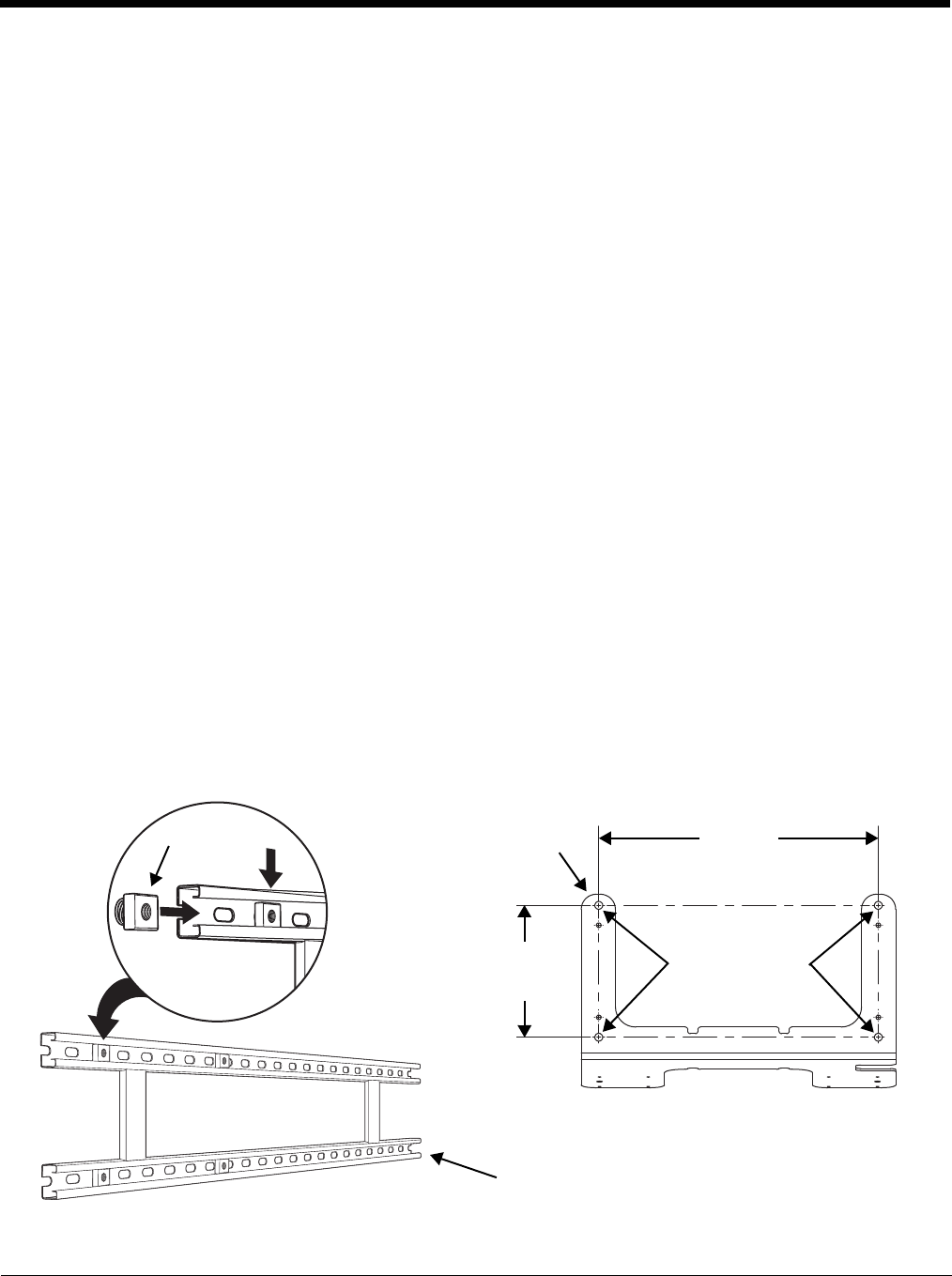
Channel Bracket Installation (Pre-existing Hardware Installations)
When choosing a location and installing the optional channel bracket:
• Do not exceed 150 lbs. maximum load on the channel bracket.
• Leave a minimum of 16 in. (40.64 cm) of horizontal space between the hardware used to attach the
channel bracket to the wall.
• An electrical outlet must be easily accessible.
• The mounting location should be dry, stable, easily accessible, and well lighted.
Tools Required
•Drill
• 7/8 in. Drill Bit (for hollow wall installations) or 1/4 in. Drill Bit (for wood stud installations)
• #2 Phillips Screw Driver
• Medium Flat Head Screw Driver
• 9/16 in.Socket Wrench
Hardware Required
• 3/8 in.-16 spring nut, for 13/16 in. deep strut, Qty. 4 per wall bracket
• 3/8 in. flat washer, Qty. 4 per wall bracket
• 3/8 in.-16 x 1.00 in., cap screw, grade 5, Qty. 4 per wall bracket
•
Hollow Wall Installations:
3/8 in. x 4 in. round head toggle bolt, 2-5/8 in. usable length, Qty. 4
3/8 in. flat washer, Qty. 4
•
Wood Stud Installations:
3/8 in. x 2 1/2 in. length hex head lag screw, Qty. 4
3/8 in. fat washer, Qty. 4
Installation
1. Slide the spring nuts into the channel of the bracket and position them to line up with the mounting
holes on the wall bracket.
Wall Mount Holes
6.5 in.
[16.5 cm]
13.78 in.
[35 cm]
Wall Bracket
Channel Bracket
Spring Nut

15 - 9
2. Attach the channel bracket to a dry, stable surface using the hardware listed on page 15-8 for the
appropriate mounting surface.
Mounting into Wood Stud
Mounting into Hollow Surface
3. Align the mounting holes on the wall bracket with the spring nuts installed in the channel bracket.
Secure the wall bracket in place using the cap screws listed on page 15-8.
4. See Securing the Base to the Wall Bracket (page 15-6) for detailed instructions on securing the
ChargeBase to the wall bracket.
Lag Bolt, Qty. 4
Channel Bracket
Minimum
16 in. (40.64 cm)
Washer, Qty. 4
Toggle Bolt, Qty. 4
Channel Bracket
Minimum
16 in. (40.64 cm)
Washer, Qty. 4
Toggle Nut, Qty. 4
15 - 10
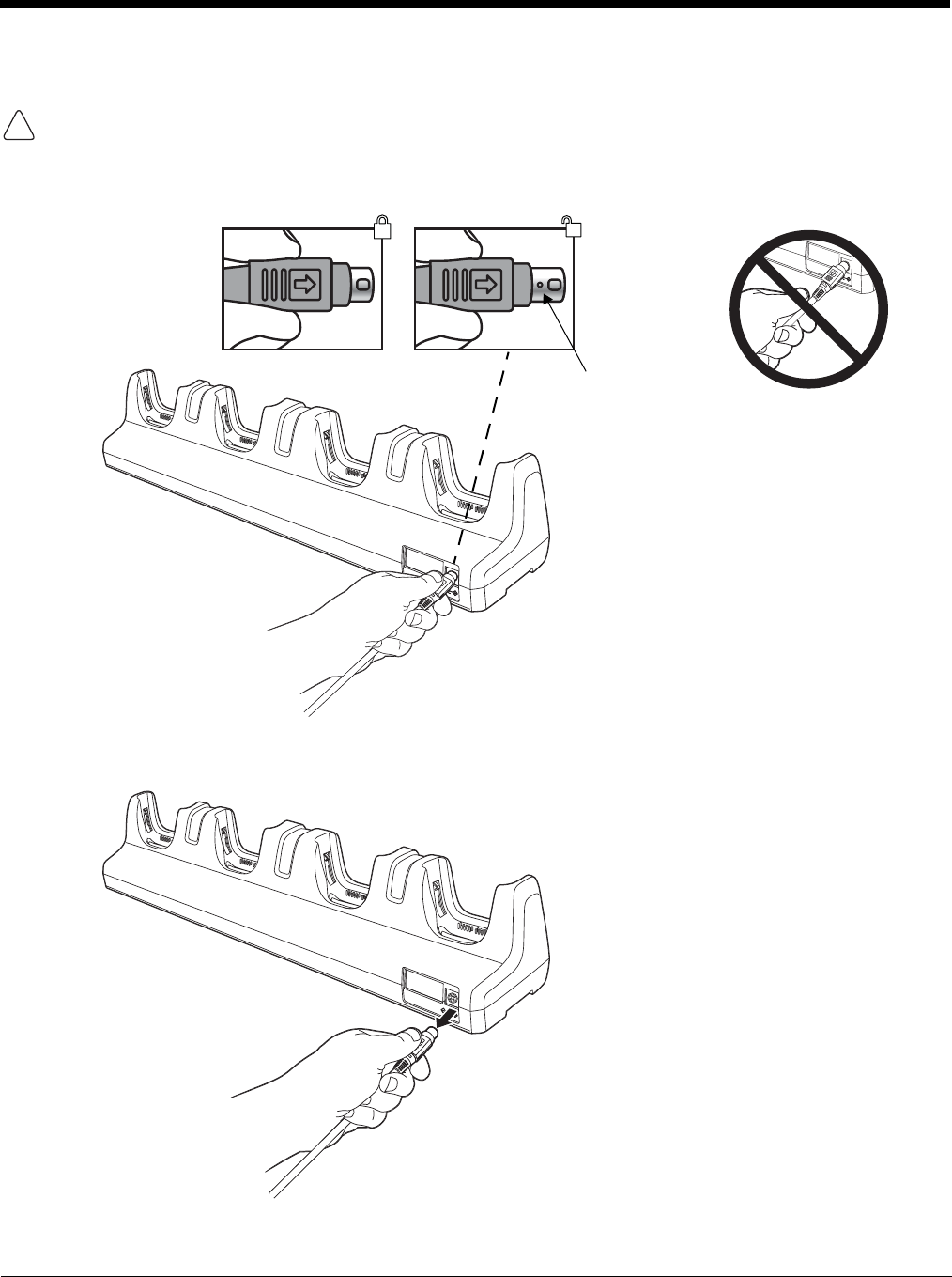
Removing Power to the ChargeBase
Attempting to remove the cable without disengaging the lock may result in damage to the base and power
cable not covered by the warranty.
1. Gently slide back the outer shell of the connector to disengage cable lock.
2. Remove the cable from the power jack.
!
Do not pull on the
power connector
cable or strain relief.
Cable Lock

16 - 1
16
Dolphin 99EX Net Base Device (Model 99EX-NB)
Overview
The Net Base enables up to four Dolphin 99EX or 99GX mobile computers to communicate with a host
device over an Ethernet network. In addition, the Net Base provides a second RJ45 Ethernet port for
connection to an additional device such as a printer, workstation, eBase, or another Net Base.
The 99EX-NB charger is designed for use with battery pack models 99EX-BTSC (standard Li-poly 3.7 V,
11.3 watt hour) and 99EX-BTEC (extended Li-ion 3.7 V, 18.5 watt hour) manufactured by Honeywell
International Inc. and with Dolphin 99EX and 99GX model terminals.
The Net Base is not designed for use in hazardous locations.
We recommend use of Honeywell peripherals, power cables, and power adapters. Use of any non-Honeywell
peripherals, cables, or power adapters may cause damage not covered by the warranty.
Unpacking the Net Base
Open the shipping box and inspect the package to see that the following standard items are included:
• One Dolphin Net Base Ethernet cradle, model 99EX-NB
• One power supply (see Power on page 16-4)
• One power cord
You will also need to provide a standard CAT-5 Ethernet network cable. These items are needed to set
up and operate the Net Base. If any items are missing or anything appears to be damaged, contact your
Customer Account Representative.
Keep the original packaging in case you need to return the Net Base for service or to store the Net Base
while not in use.
Charge Time
The base supplies power to the intelligent battery charging system in all Dolphin terminals, which senses
when a full charge has been achieved and switches to a trickle charge to maintain the full charge.
As battery packs charge, the charging circuitry follows the two-step charging process (CC-CV) that is
recommended for Li-ion or Li-poly batteries. The process monitors changes in temperature, current, and
voltage. The main battery of each terminal charges in 4 hours for the standard 3.7V battery or 6 hours for
the extended 3.7V battery.
Convenient Storage
Intelligent battery charging makes this base a safe and convenient storage receptacle for your Dolphin
terminal.
Capacity
The base can hold up to 4 Dolphin terminals. Each charging well charges each terminal independently of
the other wells.
We recommend use of Honeywell Li-ion or Li-poly battery packs. Use of any non-Honeywell battery may result
in damage not covered by the warranty.
!
!
!
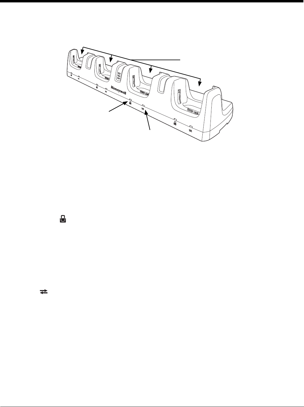
16 - 2
Parts and Functions
Front Panel
Terminal Wells
The Net Base contains four terminal wells. Each well has its own dedicated Power/Dock LED
and COMM LED indicator.
Place the Dolphin terminal in any one of the four wells to communicate with a host device,
power the terminal, and charge the installed battery pack. The Net Base completely charges
the main battery in a Dolphin terminal in 4 hours for the standard 3.7V battery or 6 hours for
the extended 3.7 battery.
Power/DOCK LED
Indicates if power is supplied to the Net Base and if a terminal is docked properly in the terminal
well. Each terminal well has its own dedicated Dock LED.
COMM LED
The COMM LED indicates the status of connection and data transfer between the Dolphin
terminal and the Net Base. Each terminal well has its own dedicated COMM LED.
Note: The COMM LED does not necessarily indicate the Net Base and terminal are connected to a valid Ethernet
link. For more information, see RJ45 Ethernet Ports on page 16-3.
This color means…
Red The Net Base has power but no terminal is docked.
Green The Net Base has power and the terminal is properly seated in the base.
When the Dolphin terminal is docked:
This color and status means…
Green Solid A connection has been established between the Dolphin terminal
and the Net Base.
Green Flashing Data transfer in progress.
COMM LED
Power/Dock LED
Terminal Wells
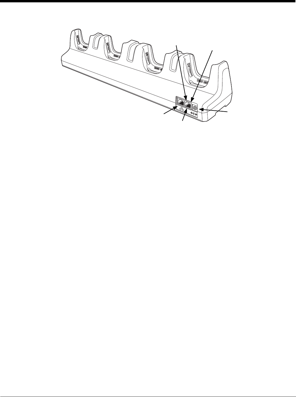
16 - 3
Back Panel
DC Power Jack
Use the power cable from Honeywell that comes with the Net Base to supply power to this
power jack. For more information, see Power on page 16-4.
RJ45 Ethernet Ports
The Net Base contains two RJ45 Ethernet ports. You can connect the Net Base to an Ethernet-
compliant device to facilitate Ethernet communication to and from the terminal by plugging a
standard CAT-5 Ethernet cable into one of the two Ethernet ports provided. The second RJ45
Ethernet port can be used for connection to an additional device such as a printer, workstation,
eBase, or another Net Base.
Note: The Net Base does not use a Spanning Tree Protocol (STP). When both RJ45 Ethernet ports
are used, do not connect both Net Base interfaces to the same layer 2 LAN.
Note: Ethernet Port 2 only supports 100Mbps Ethernet connections. Plugging in a 10Mbps connection
into Port 2 may cause other ports to stop working. For 10Mbps connections use Ethernet Port 1.
Each Ethernet port has a dedicated green and yellow status LED.
Note: The terminal and Ethernet link must be set up properly to allow the terminal to communicate to other devices
and/or the Internet. For more information, see Connecting the Dolphin Terminal to the Net Base on page 16-5.
This color and status means…
Green Flashing Data transfer is in progress.
Solid A connection has been established between the Net Base and
the Ethernet.
Yellow Solid Ethernet is connected at 100T.
Off Ethernet is connected at 10T.
DC Power Jack
Port 2: 100Mbps Only RJ45 Ethernet Port
Green LED Yellow LED
Port 1: 10/100Mbps RJ45 Ethernet Port
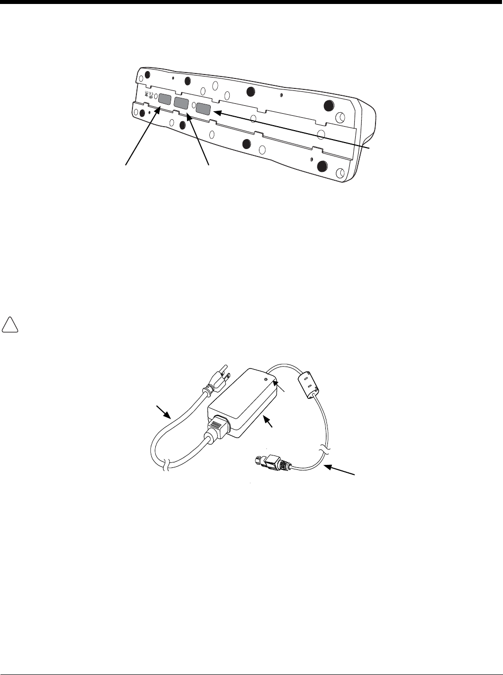
16 - 4
Bottom Panel
For details on how to mount the Net Base, see Mounting the Net Base on page 16-6.
Power
The terminal requires 12 Volts DC input for communications and battery charging; the power adapter on
the power cable converts the voltage from the power source to 12 volts DC. Use only UL Listed power
supply, which has been qualified by Honeywell with output rated at 12VDC and 8.5 amps with the device.
The operating temperature range is -10° to 50°C (14° to 122°F).
Honeywell recommends that you leave the Net Base connected to its power source at all times, so that it
is always ready to use.
We recommend use of Honeywell peripherals, power cables, and power adapters. Use of any non-Honeywell
peripherals, cables, or power adapters may cause damage not covered by the warranty.
Connecting Power to the Net Base
1. Plug the A/C power cord into the power adapter.
2. Plug the power connector cable into the power connector on the back of the Net Base.
3. Plug the A/C power cord into a standard wall outlet. The LED on the Power Adapter illuminates to
indicate power.
4. All four Power/Dock LEDs illuminate solid red to indicate the base has power. Terminal wells with
properly docked Dolphins indicate power with a green LED.
5. The base is ready to begin charging terminals.
Compliance Label Serial Number Label
MAC Address Label
!
Power Connector Cable
A/C Power Cord
Power
Adapter
LED
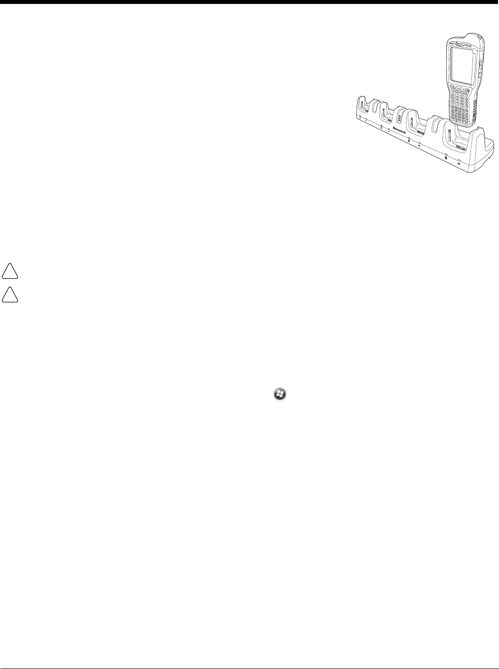
16 - 5
Charging the Main Battery
The base provides power to the Dolphin terminals and allows the
charging of the main batteries in the terminals. The main battery of
each terminal charges in 4 hours for the standard 3.7V battery or
6 hours for the extended 3.7V battery. The intelligent battery charging
system incorporated into all Dolphin terminals prevents overcharging,
which means that Dolphin terminals may be stored in the base indefi-
nitely without damage to the terminals, battery packs, or the base.
To Power a Terminal and Charge its Main Battery
1. Install the main battery pack in the terminal; see Install the Main Battery Pack on page 2-1.
2. Verify the base has power. If the Power/Dock LEDs are not illuminated, see Connecting Power to
the Net Base on page 16-4.
3. Slide the Dolphin terminal into one of the four terminal wells. The the Power/Dock LED for the well
changes to green. Charging begins immediately if required by the Dolphin terminal.
Ensure all components are dry prior to mating terminals/batteries with peripheral devices. Mating wet
components may cause damage not covered by the warranty.
We recommend use of Honeywell Li-Ion or Li-poly battery packs. Use of any non-Honeywell battery may result
in damage not covered by the warranty.
Communication
Software Requirements
Before you connect the Dolphin terminal to the Net Base, make sure you have the most current software
installed. To check the terminal’s system information, tap > Power Tools > SysInfo.
• The Kernel version must be 26.01 or later in terminals running Windows Embedded Handheld 6.5
Classic.
• In terminals running Windows Embedded Handheld 6.5 Professional, the kernel version must be 25.01
or later.
Applications on the Dolphin Terminal
Applications running on the Dolphin terminal when it is connected to the Net Base should be designed
specifically for a partially connected network. For more details, please refer to the
Best Practices for Par-
tially Connected Networks
document available at www.honeywellaidc.com.
Connecting the Dolphin Terminal to the Net Base
By default, the Dolphin terminal is configured to obtain IP addresses automatically using a DHCP server.
This means that in most cases, you would simply plug-and-play the unit.
1. Verify the base has power. If the Power/Dock LEDs are not illuminated, see Connecting Power to
the Net Base on page 16-4.
2. Plug the CAT-5 Ethernet cable into one of the RJ45 connectors on the back of the Net Base.
!
!
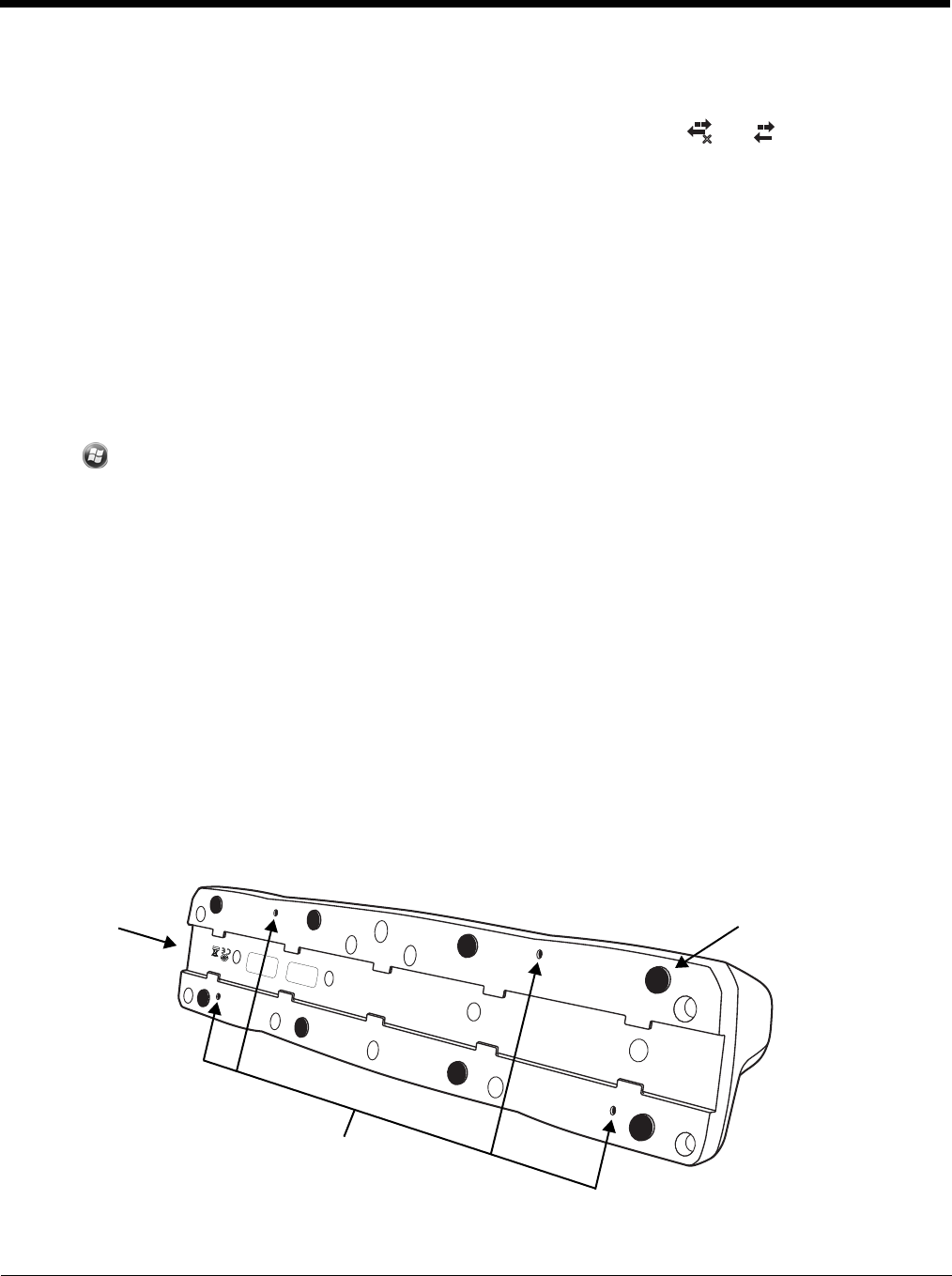
16 - 6
3. Plug the Ethernet cable into the network.
4. Insert the Dolphin into one of the terminal wells. The DOCK LED for the well changes from red to
green and the connection icon on the Dolphin’s title bar changes from to .
5. By default, the DHCP server assigns a unique IP address to each of the Dolphin terminals docked in
the Net Base. This IP address can be used by any application on the Dolphin terminal.
Note: Instead of using the default for DHCP assigned IP addresses, the Dolphin terminal can use a statically
assigned IP address. See standard Microsoft Windows Mobile documentation for how to assign a static IP
address to a network adapter. In this case, set a static IP address for the adapter named "SMC95001 USB2.0
FAST Ethernet Drive".
Displaying the Net Base Terminal Well and Dolphin IP Address
Once the Dolphin terminal establishes communication, it uses the unique IP address assigned to the ter-
minal well it is docked in on the Net Base. If four Dolphin terminals are successfully connected, then four
different IP addresses are assigned to the adapter associated with the Dolphin terminal.
1. Tap
> Power Tools > Network Utilities > IPConfig.
2. Change the Adapter to SMC95001.
3. On the Input tab, tap the Display full configuration button.
4. The Dolphin terminal retrieves and displays the IP configuration for the entire Dolphin terminal and
the Net Base terminal well where the Dolphin is docked.
5. Locate the IpAddress
field in the IP configuration list.
Mounting the Net Base
Set the Net Base on a dry, stable surface, such as a desktop or workbench near an electrical outlet. Be
sure to provide enough workspace with good lighting for the user to view and operate the Dolphin termi-
nal while it is in the Net Base. When choosing a location, bear in mind that the mounting location must
allow users easy access to the terminal wells, the Ethernet ports, and the power jack.
Bottom Panel
x
DIN Rail Slot Rubber Feet, Qty. 8
Mounting Holes for Wall
Mount Bracket Hardware,
Qty. 4
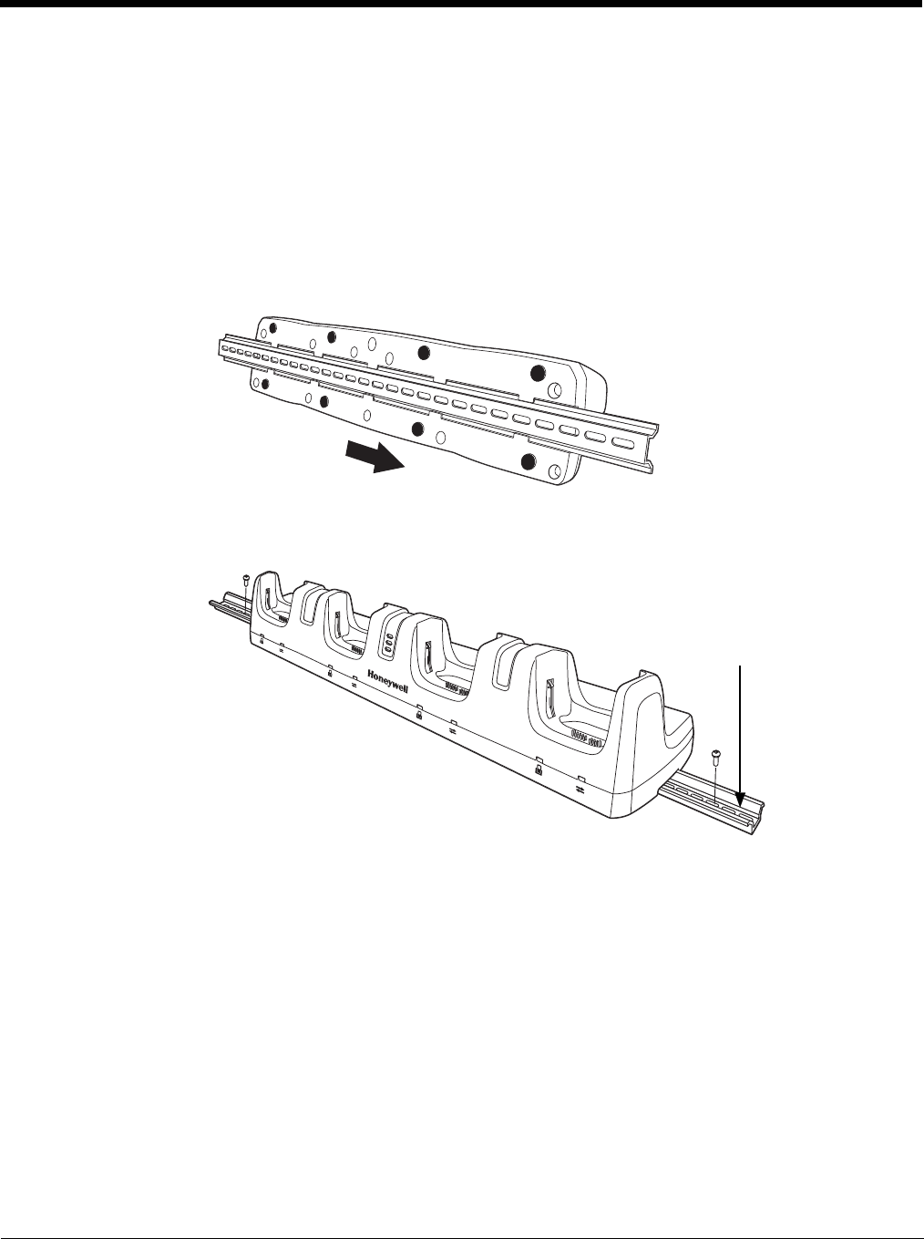
16 - 7
Desk Mounting
The DIN Rail (7.5 X 35 mm) slot on the bottom panel enables secure mounting on a horizontal surface.
Hardware Required
• 3/16 in. dia x 5/8 in. long pan head screw
• 1/2 in. OD x 7/32 in. ID x 3/64 in. thick washer
• 3/16 in. dia nut
Installing the DIN Rail
1. Slide the DIN Rail into the DIN Rail slot on the bottom panel of the base.
2. Turn the base and DIN Rail right side up.
3. Then, using the appropriate hardware, secure the DIN Rail to a stable, flat horizontal surface.
Wall Mounting
The optional wall mount bracket enables secure mounting of the base on a vertical surface. The wall
mount bracket can be used in conjunction with the DIN rail but does not require the DIN Rail for use.
Hardware (Provided)
• M3 x 9 mm self-tapping screws, #2 Phillips, Qty. 4
• 3/8 in. x 4 in. round head toggle bolt, 2-5/8 in. usable length, Qty. 4
• 3/8 in. x 2 1/2 in. length Hex Head Lag Screw, Qty. 4
Tools Required
•Drill
• 7/8 in. Drill Bit (for hollow wall installations) or
1/4 in. Drill Bit (for wood stud installation)
• Phillips Screw Driver
DIN Rail (7.5 X 35 mm)

16 - 8
Hollow Wall Installation
1. Drill four pilot holes in the wall using a 7/8 in. drill bit.
2. Slide the bolt through the wall bracket, and thread the toggle nut onto
the bolt.
3. Press the ends of the toggle nut together, and insert the bolt/nut into the
pilot hole until the nut clears inside wall surface. The toggle nut should
spring open preventing the screw from being removed.
4. Repeat steps 2 and 3 for each of the remaining mounting holes.
5. Tighten all four bolts to secure the bracket to the wall.
6. Once the bracket is installed, secure the base to the wall bracket, see
Securing the Base to the Wall Bracket for detailed instructions.
Wood Stud Installation
1. Drill four pilot holes in the wall/wood stud using the 1/4 in. drill bit.
2. Secure the bracket to the wall using the four Hex Head Lag Screws provided.
3. Once the bracket is installed, secure the base to the wall bracket, Securing the Base to the Wall
Bracket for detailed instructions.
Securing the Base to the Wall Bracket
You can secure the base to the wall bracket by
using the self tapping screws provided or you can
use the optional DIN Rail.
To secure the base using the self tapping screws:
1. Position the base on the wall bracket, as
shown.
2. Secure the base to the bracket using the four
M3 x 9 mm self-tapping screws provided.
Wall Mount Holes
6.5 in.
[16.5 cm]
13.78 in.
[35 cm]
Wall Mount Bracket
Bolt
Bracket
Wall
Toggle Nut
Open
Toggle Nut
Wall
Bracket
Wall Bracket
M3 x 9 mm Self-tapping
Screws, Qty. 4

16 - 9
To secure the base using the optional DIN Rail:
Hardware Required
• DIN Rail, Qty. 1
• 3/16 in. dia x 5/8 in. long pan head screw, Qty. 2
• 1/2 in. OD x 7/32 in. ID x 3/64 in. thick washer, Qty. 2
• 3/16 in. dia nut, Qty. 2
1. Position the DIN Rail on the wall bracket, as shown below.
2. Slide the screw through the slot on the DIN Rail and the mounting hole in the bracket.
3. Slide the washer onto the screw and tighten the nut to secure the assembly.
4. Remove the rubber feet on the bottom of the Net Base.
5. Slide the base onto the DIN Rail using the slot on the bottom of the base.
Wall Bracket, Qty. 1
DIN Rail, Qty. 1
Washer, Qty. 1
Nut, Qty. 1
Screw, Qty. 2
Washer, Qty. 1
Nut, Qty. 1
Wall Bracket
Wall Bracket
DIN Rail

16 - 10
Channel Bracket Installation (Pre-existing Hardware Installations)
When choosing a location and installing the optional channel bracket:
• Do not exceed 150 lbs. maximum load on the channel bracket.
• Leave a minimum of 16 in. (40.64 cm) of horizontal space between the hardware used to attach the
channel bracket to the wall.
• An electrical outlet must be easily accessible.
• The mounting location should be dry, stable, easily accessible, and well lighted.
Tools Required
•Drill
• 7/8 in. Drill Bit (for hollow wall installations) or 1/4 in. Drill Bit (for wood stud installations)
• #2 Phillips Screw Driver
• Medium Flat Head Screw Driver
• 9/16 in.Socket Wrench
Hardware Required
• 3/8 in.-16 spring nut, for 13/16 in. deep strut, Qty. 4 per wall bracket
• 3/8 in. flat washer, Qty. 4 per wall bracket
• 3/8 in.-16 x 1.00 in., cap screw, grade 5, Qty. 4 per wall bracket
•
Hollow Wall Installations:
3/8 in. x 4 in. round head toggle bolt, 2-5/8 in. usable length, Qty. 4
3/8 in. flat washer, Qty. 4
•
Wood Stud Installations:
3/8 in. x 2 1/2 in. length hex head lag screw, Qty. 4
3/8 in. fat washer, Qty. 4
Installation
1. Slide the spring nuts into the channel of the bracket and position them to line up with the mounting
holes on the wall bracket.
Wall Mount Holes
6.5 in.
[16.5 cm]
13.78 in.
[35 cm]
Wall Bracket
Channel Bracket
Spring Nut
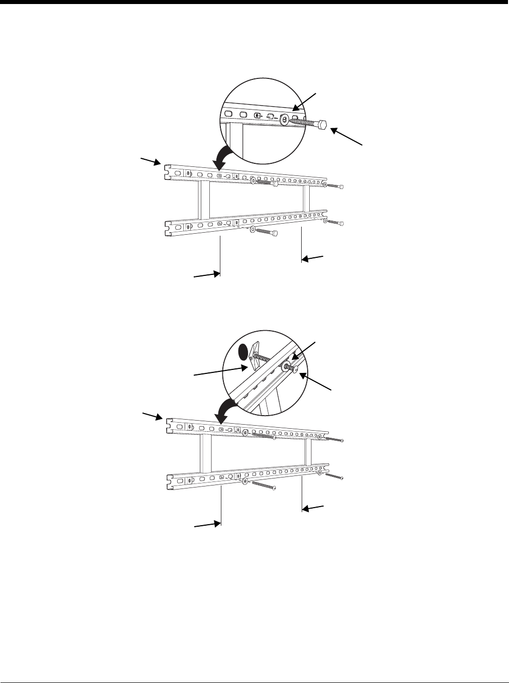
16 - 11
2. Attach the channel bracket to a dry, stable surface using the hardware listed on page 16-10 for the
appropriate mounting surface.
Mounting into Wood Stud
Mounting into Hollow Surface
3. Align the mounting holes on the wall bracket with the spring nuts installed in the channel bracket.
Secure the wall bracket in place using the cap screws listed on page 16-10.
4. See Securing the Base to the Wall Bracket (page 16-8) for detailed instructions on securing the Net
Base to the wall bracket.
Lag Bolt, Qty. 4
Channel Bracket
Minimum
16 in. (40.64 cm)
Washer, Qty. 4
Toggle Bolt, Qty. 4
Channel Bracket
Minimum
16 in. (40.64 cm)
Washer, Qty. 4
Toggle Nut, Qty. 4

16 - 12
Removing Power to the Net Base
Attempting to remove the cable without disengaging the lock may result in damage to the base and power
cable not covered by the warranty.
1. Gently slide back the outer shell of the connector to disengage cable lock.
2. Remove the cable from the power jack.
!
Cable Lock
Do not pull on the
power connector
cable or strain relief.

17 - 1
17
Dolphin 99EX QuadCharger Device (Model 99EX-QC)
Overview
This 4-slot charging station provides intelligent battery management for the rechargeable battery packs
used in Dolphin terminals.
The 99EX-QC charger is designed for use with battery pack models 99EX-BTSC (standard Li-poly 3.7 V,
11.3 watt hour) and 99EX-BTEC (extended Li-ion 3.7 V, 18.5 watt hour) manufactured for Honeywell
International Inc.
Note: The QuadCharger is not designed for use in hazardous locations.
Unpacking the QuadCharger
Open the shipping box and inspect the package to see that the following standard items are included:
• One Dolphin 99EX QuadCharger, model 99EX-QC
• One power supply (see Supplying Power on page 17-3)
• One power cord
If any items are missing or anything appears to be damaged, contact your Customer Account Represen-
tative. Keep the original packaging in case you need to return the Net Base for service or to store the Net
Base while not in use.
Capacity
The charger holds 4 Honeywell standard or extended batteries.
Charging Time
Charge time is 4 hours for the standard 3.7V battery or 6 hours for the extended 3.7V battery.
Charging Process
Each charging slot works independently of the other three. As battery packs charge, the charging cir-
cuitry follows the two-step charging process (CC-CV) that is recommended for Li-ion and Li-poly batter-
ies. The process monitors changes in temperature, current, and voltage and resets the battery pack.
We recommend use of Honeywell Li-Ion or Li-poly battery packs. Use of any non-Honeywell battery may result
in damage not covered by the warranty.
We recommend use of Honeywell peripherals, power cables, and power adapters. Use of any non-Honeywell
peripherals, cables, or power adapters may cause damage not covered by the warranty.
!
!
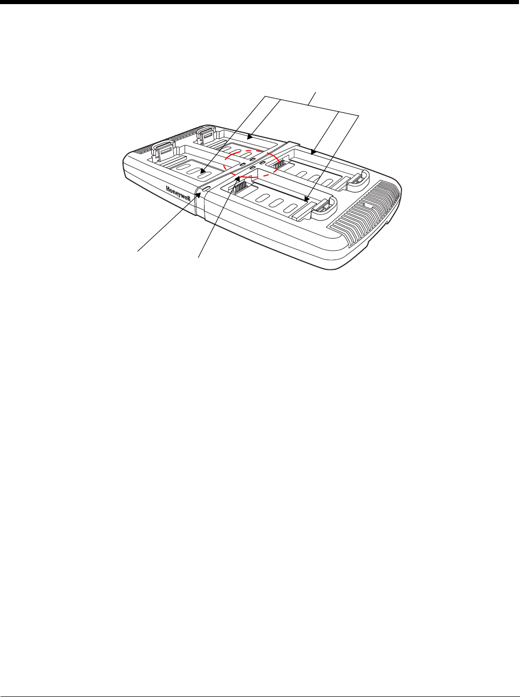
17 - 2
Parts and Functions
Top Panel
Charging Slots
There are 4 charging slots. Each slot holds one Li-ion or Li-poly battery and charges it
independently of the other slots. When a battery is placed in each slot, it immediately begins
charging.
Power LED
The power LED indicates if the QuadCharger is powered and operational. When the
QuadCharger is receiving power, the LED illuminates green.
Power Supply Connector
You attach the power supply to this connector. See Supplying Power on page 17-3.
Status LEDs
A status LED is located at one corner of each of the 4 battery slots. The color of the LED
indicates the charge status of the batteries in its slot.
Color This color indicates that the battery in the slot…
Green (Solid) Has completed its charge cycle and is ready for use.
Orange (Solid) Is being charged at a maximum charge rate.
Red (Flashing) The internal temperature of the auxiliary battery is too hot or there
is a battery error. Charge the auxiliary battery in a cooler
environment or replace the battery with a new Honeywell Li-ion or
Li-poly battery.
For more information, see Troubleshooting on page 17-5.
Charging Slots (4)
Status LEDs
One Per Charging Slot
Power LED
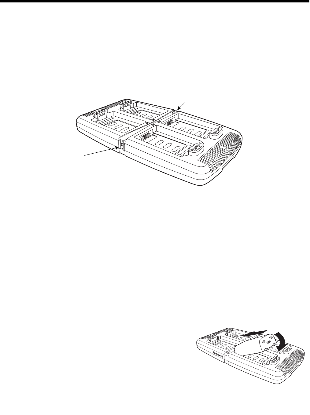
17 - 3
Supplying Power
The charger must be connected to a power source via the Honeywell power adapter cable so that volt-
age is adjusted appropriately. Use only UL Listed power supply, which has been qualified by Honeywell
with output rated at 12VDC and 3 amps with the device.
1. Locate the AC power adapter cable and plug it into the power source.
2. Connect the power cable to the power adapter.
3. Connect the power cable to the supply connector on the back of the charger.
4. The power LED illuminates green, and the charger performs a self-diagnostic test that lasts
approximately five seconds.
Recommendations for Storing Batteries
To maintain top performance from batteries, avoid storing batteries outside of the following temperature
ranges:
• 14°F to 113°F (-10°C to +45°C) for short term storage of less than one month
• 32°F to 86°F (-0°C to +30°C) for long term storage
Do not store batteries in extremely high humidity. For prolonged storage, do not keep batteries stored in
a charger that is connected to a power source.
Inserting and Charging Batteries
For best results, battery packs should be at room temperature before recharging them; temperature has
a marked effect on charging. The recommended temperature range is 50°F to 95° F (10°C to 35° C).
1. Set up the charger, see Supplying Power above.
2. Power the charger. The Power LED illuminates green.
3. Insert the battery at an angle so the battery pack contacts
and the QuadCharger contacts align.
4. Snap the battery into place with a hinging motion.
5. The Status LED for that particular slot illuminates orange to
indicate the battery is seated properly and the charging cycle has begun.
6. When the Status LED turns green, the battery in the slot has completed charging.
Power Supply
Connector
Power LED
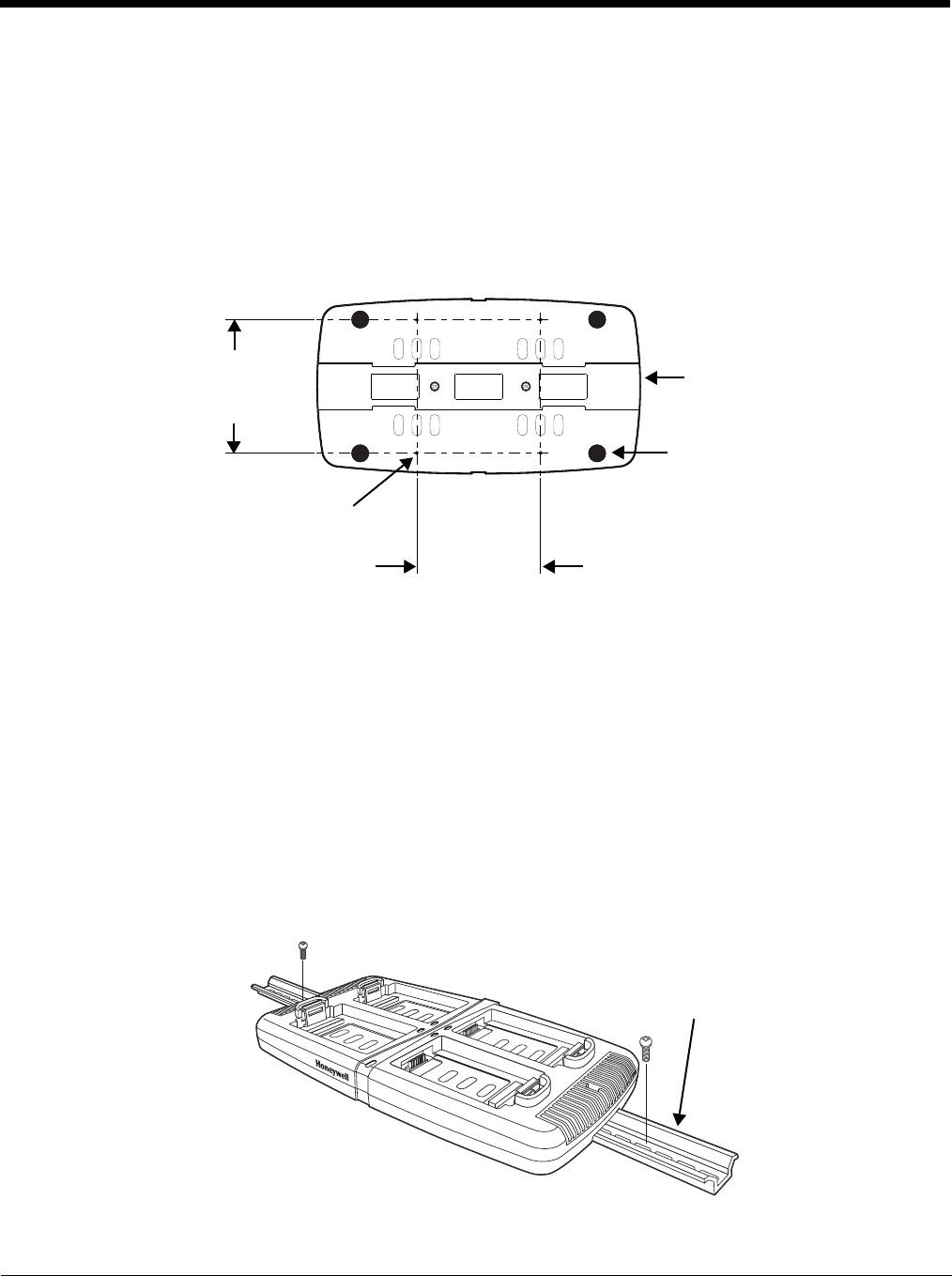
17 - 4
Mounting the QuadCharger
The charger should be on a dry, stable surface and can be mounted on a flat, horizontal surface such as
a desktop or workbench. When choosing a location, always bear in mind that:
• the mounting location must allow users easy access to the power connector.
• the charger should be oriented so that users can easily insert and remove battery packs and see the
LEDs.
Bottom Panel
Desk Mounting
The DIN rail slot on the bottom panel enables secure mounting to a horizontal surface.
Hardware Required
• 3/16 in. dia x 5/8 in. long pan head screw
• 1/2 in. OD x 7/32 in. ID x 3/64 in. thick washer
• 3/16 in. dia nut
Installing the DIN Rail
1. Slide the DIN rail into the DIN rail slot (7.5 X 35 mm) on the bottom of the QuadCharger.
2. Then, using the appropriate hardware listed above, secure the DIN rail to the desktop.
DIN Rail Slot
Rubber Feet,
Qty. 4
3.94 in.
[10 cm]
3.66 in.
[9.3 cm]
Optional Mounting Holes
for M3 Self-Tapping
Screws, Qty. 4
DIN Rail

17 - 5
Troubleshooting
If you encounter problems with your QuadCharger device, refer to chart below for possible solutions.
If problems persist, please contact Honeywell Technical Support.
Problem Issue
The Status LED does not come on when I
insert a battery pack. Check the power connections; make sure the Power cable is
inserted into the Power supply connector and the battery pack
is properly seated.
The Status LED lights red during charging. Try to charge the battery in one of the other charging slots. If
the red Status LED comes on again, then the problem is
associated with the battery pack. If the red status stays with the
charging slot, the problem is associated with the charging
circuitry.
The Status LED flashes red without a
battery in the charging slot. If a battery is in failure mode (flashing red LED), and that
battery is removed from the charging slot, the slot does not
reset and will continue to flash red. To reset the slot and stop
the flashing red LED, insert a known good battery into the slot
or recycle the power to the QuadCharger.

17 - 6

18 - 1
18
Customer Support
Product Service and Repair
Honeywell International Inc. provides service for all of its products through service centers throughout
the world. To obtain warranty or non-warranty service, please visit www.honeywellaidc.com, and select
Support > Contact Service and Repair to see your region’s instructions on how to obtain a Return
Material Authorization number (RMA #). You should do this prior to returning the product.
For ongoing and future product quality improvement initiatives, the 99EX comes equipped with an
embedded device lifetime counter function. Honeywell may use lifetime counter data for future statistical
reliability analysis as well as ongoing quality, repair and service purposes.
Technical Assistance
If you need assistance installing or troubleshooting your device, please contact us by using one of the
methods below:
Knowledge Base: www.hsmknowledgebase.com
Our Knowledge Base provides thousands of immediate solutions. If the Knowledge Base cannot help,
our Technical Support Portal (see below) provides an easy way to report your problem or ask your ques-
tion.
Technical Support Portal: www.hsmsupportportal.com
The Technical Support Portal not only allows you to report your problem, but it also provides immediate
solutions to your technical issues by searching our Knowledge Base. With the Portal, you can submit
and track your questions online and send and receive attachments.
Web form: www.hsmcontactsupport.com
You can contact our technical support team directly by filling out our online support form. Enter your
contact details and the description of the question/problem.
Telephone: www.honeywellaidc.com/locations
For our latest contact information, please check our website at the link above.
Limited Warranty
Honeywell International Inc. ("HII") warrants its products and optional accessories to be free from defects
in materials and workmanship and to conform to HII’s published specifications applicable to the products
purchased at the time of shipment. This warranty does not cover any HII product which is (i) improperly
installed or used; (ii) damaged by accident or negligence, including failure to follow the proper
maintenance, service, and cleaning schedule; or (iii) damaged as a result of (A) modification or alteration
by the purchaser or other party, (B) excessive voltage or current supplied to or drawn from the interface
connections, (C) static electricity or electro-static discharge, (D) operation under conditions beyond the
specified operating parameters, or (E) repair or service of the product by anyone other than HII or its
authorized representatives.
This warranty shall extend from the time of shipment for the duration published by HII for the product at
the time of purchase ("Warranty Period"). Any defective product must be returned (at purchaser’s
expense) during the Warranty Period to HII factory or authorized service center for inspection. No product
will be accepted by HII without a Return Materials Authorization, which may be obtained by contacting

18 - 2
HII. In the event that the product is returned to HII or its authorized service center within the Warranty
Period and HII determines to its satisfaction that the product is defective due to defects in materials or
workmanship, HII, at its sole option, will either repair or replace the product without charge, except for
return shipping to HII.
EXCEPT AS MAY BE OTHERWISE PROVIDED BY APPLICABLE LAW, THE FOREGOING
WARRANTY IS IN LIEU OF ALL OTHER COVENANTS OR WARRANTIES, EITHER EXPRESSED OR
IMPLIED, ORAL OR WRITTEN, INCLUDING, WITHOUT LIMITATION, ANY IMPLIED WARRANTIES
OF MERCHANTABILITY OR FITNESS FOR A PARTICULAR PURPOSE, OR NON-INFRINGEMENT.
HII’S RESPONSIBILITY AND PURCHASER’S EXCLUSIVE REMEDY UNDER THIS WARRANTY IS
LIMITED TO THE REPAIR OR REPLACEMENT OF THE DEFECTIVE PRODUCT WITH NEW OR
REFURBISHED PARTS. IN NO EVENT SHALL HII BE LIABLE FOR INDIRECT, INCIDENTAL, OR
CONSEQUENTIAL DAMAGES, AND, IN NO EVENT, SHALL ANY LIABILITY OF HII ARISING IN
CONNECTION WITH ANY PRODUCT SOLD HEREUNDER (WHETHER SUCH LIABILITY ARISES
FROM A CLAIM BASED ON CONTRACT, WARRANTY, TORT, OR OTHERWISE) EXCEED THE
ACTUAL AMOUNT PAID TO HII FOR THE PRODUCT. THESE LIMITATIONS ON LIABILITY SHALL
REMAIN IN FULL FORCE AND EFFECT EVEN WHEN HII MAY HAVE BEEN ADVISED OF THE
POSSIBILITY OF SUCH INJURIES, LOSSES, OR DAMAGES. SOME STATES, PROVINCES, OR
COUNTRIES DO NOT ALLOW THE EXCLUSION OR LIMITATIONS OF INCIDENTAL OR
CONSEQUENTIAL DAMAGES, SO THE ABOVE LIMITATION OR EXCLUSION MAY NOT APPLY TO
YOU.
All provisions of this Limited Warranty are separate and severable, which means that if any provision is
held invalid and unenforceable, such determination shall not affect the validity of enforceability of the
other provisions hereof. Use of any peripherals not provided by the manufacturer may result in damage
not covered by this warranty. This includes but is not limited to: cables, power supplies, cradles, and
docking stations. HII extends these warranties only to the first end-users of the products. These
warranties are non-transferable.
The limited duration of the warranty for the Dolphin 99EX and 99GX is as follows:
• The duration of the limited warranty for terminals with an integrated imager is one year.
• The duration of the limited warranty for touch screens is one year.
• The duration of the limited warranty for the Dolphin 99EX HomeBase device, Dolphin 99EX eBase
device, Dolphin 99EX Net Base device, Dolphin 99EX QuadCharger device, Dolphin 99EX Mobile
Base, and Dolphin 99EX ChargeBase device, is one year.
• The duration of the limited warranty for batteries is one year.
Use of any battery from a source other than Honeywell may result in damage not covered by the
warranty. Batteries returned to Honeywell International Inc. in a reduced state may or not be replaced
under this warranty. Battery life will be greatly increased when following the battery instructions in this
user’s guide.
How to Extend Your Warranty
Honeywell International Inc. offers a variety of service plans on our hardware products. These
agreements offer continued coverage for your equipment after the initial warranty expires. For more
information, contact your Sales Representative, Customer Account Representative, or Product Service
Marketing Manager from Honeywell International Inc., or your Authorized Reseller.


Honeywell Scanning & Mobility
9680 Old Bailes Road
Fort Mill, SC 29707
www.honeywellaidc.com
99EX-UG Rev G
3/14