Honeywell 9PGTPA-100A TPA-100A TCAS II Processor User Manual Title1 Draft
Honeywell International Inc. TPA-100A TCAS II Processor Title1 Draft
UserManual.wiki
>
Honeywell
>
9PGTPA 100A User Manual
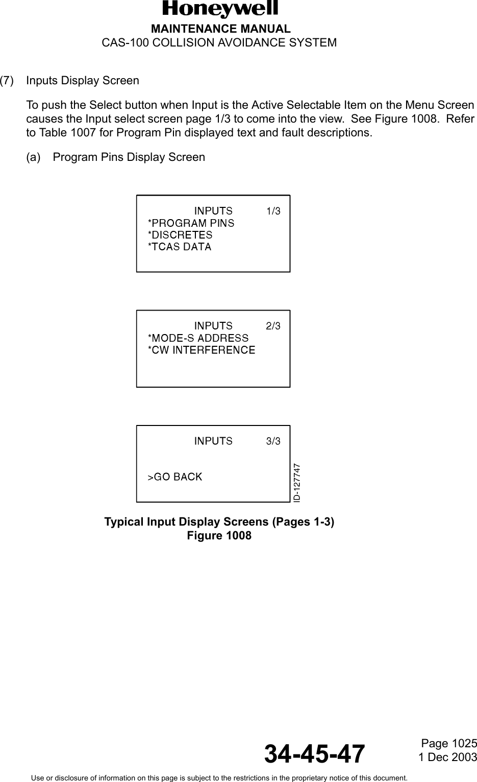
Users Manual
Navigation menu
Upload a User Manual
Namespaces
Wiki Guide
HTML
PDF
Info
Views
User Manual
Discussion / Help
Navigation
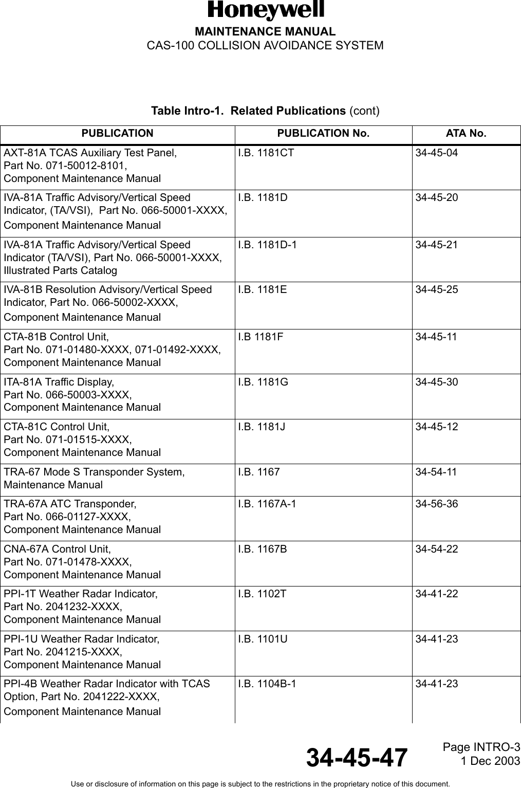
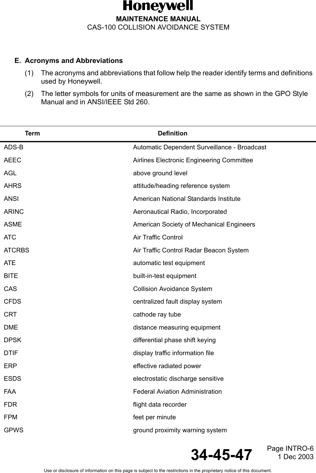
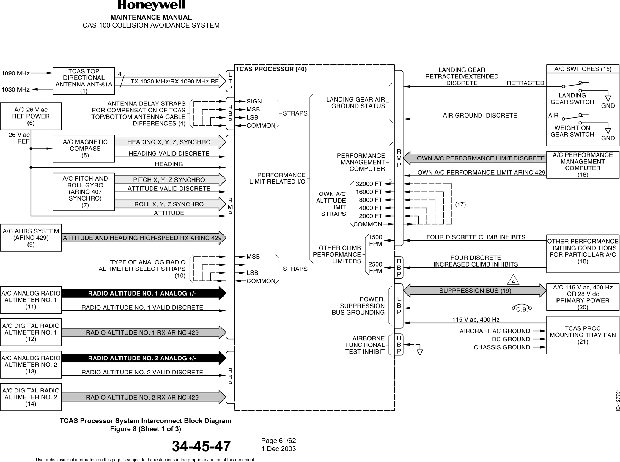
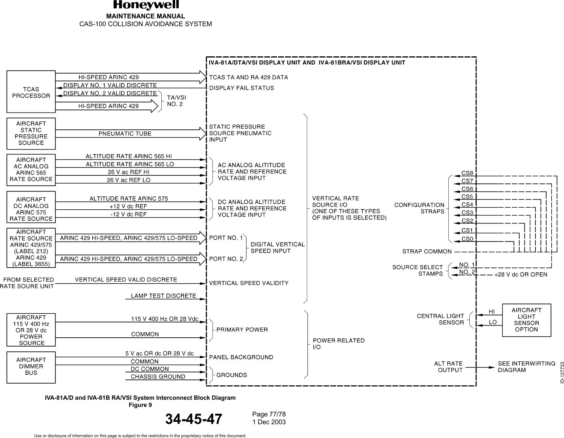
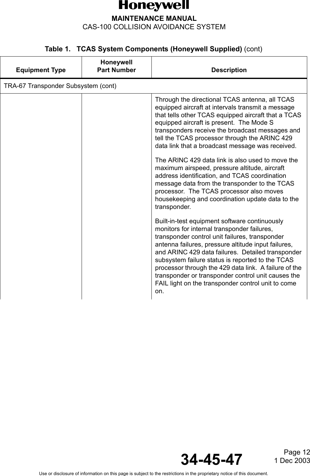
![Page 3 1 Dec 200334-45-47MAINTENANCE MANUALCAS-100 COLLISION AVOIDANCE SYSTEMUse or disclosure of information on this page is subject to the restrictions in the proprietary notice of this document.TCAS equipment operates at the same transmit and receive frequencies as ground stations (1030 MHz transmit and 1090 MHz receive). TCAS and ground stations operate at transmit and receive frequencies that are inverse to transponder transmit and receive frequencies shown below:TCAS interrogates only in Mode C and Mode S by transmitting 1030-MHz messages through the top and bottom TCAS antennas. TCAS receives 1090-MHz messages from Mode S and ATCRBS Mode A or Mode C transponders through the top directional antenna and the bottom TCAS omni or directional antenna.If TCAS receives a Mode C reply from a Mode A transponder or a Mode C transponder that is not supplied with altitude data, it will process the reply as a NAR reporting Mode C equipped aircraft.TCAS does not interrogate in Mode A. However, an aircraft equipped with a minimal transponder that replies to Mode A interrogations, will reply to Mode C interrogations with no altitude-encoded data present in the reply. TCAS tracks such aircraft in bearing and range, and will display the aircraft a nonthreat intruder, proximity intruder, or traffic advisory. However, a resolution advisory will not be generated since the correction maneuver (e.g., fly up, fly down) cannot be determined without intruder altitude data. B. Equipment Part NumbersThe required and optional TCAS equipment, including aircraft systems are:• TCAS processor (required equipment)• Top-mounted directional antenna (required equipment)• Bottom-mounted omni or directional antenna (required equipment)• Installation selectable combinations of resolution advisory (TA/VSI or RA/VSI) and traffic advisory displays [TA/VSI, plane position indicator (PPI), dedicated, etc.] (required equipment)• Mode S transponder (required equipment)• Required aircraft equipment• Optional aircraft equipment.System Transmit Frequency Receive FrequencyMode S Transponder 1090 MHz 1030 MHzMode A/C ATCRBS Transponder 1090 MHz 1030 MHzTCAS 1030 MHz 1090 MHzGround Station 1030 MHz 1090 MHz](https://usermanual.wiki/Honeywell/9PGTPA-100A/User-Guide-409222-Page-37.png)
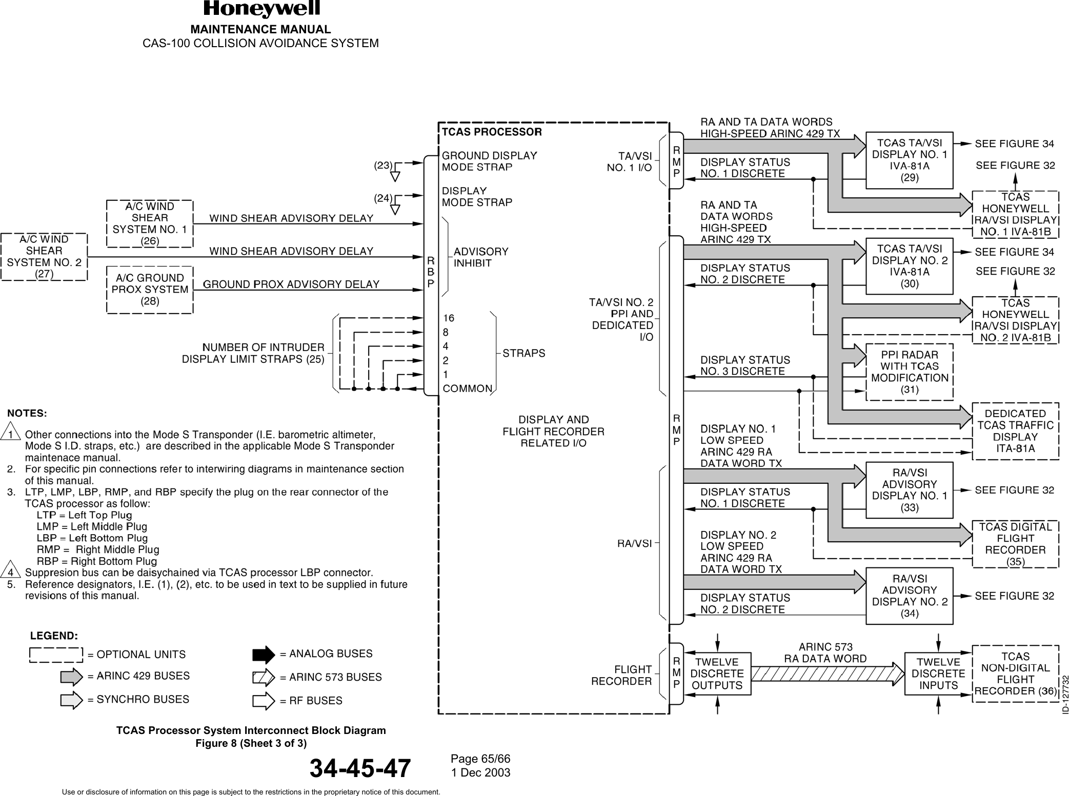
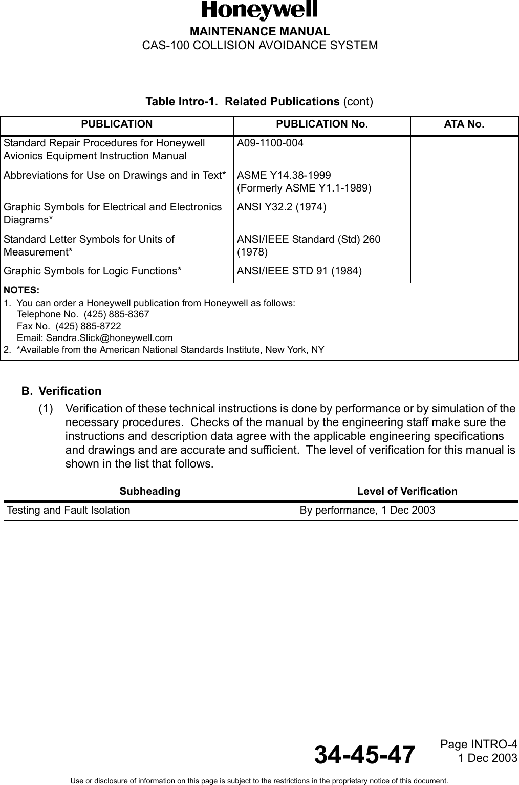
![Page 561 Dec 200334-45-47MAINTENANCE MANUALCAS-100 COLLISION AVOIDANCE SYSTEMUse or disclosure of information on this page is subject to the restrictions in the proprietary notice of this document.(j) Display range limit control, ABOVE/NORM/BELOW nonthreat altitude display limit control, and relative/flight level altitude display control data originating from the transponder/TCAS control unit and received by the traffic display through the Mode S transponder and TCAS processor. (k) Other strapped control data (For example, maximum number of intruders to be shown)Refer to Controls and Indicators, paragraph 7, for traffic display indications and annunciations.D. RA/VSI Display The IVA-81B Resolution Advisory/Vertical Speed Indicator (RA/VSI) display. It consists of:• An electro-mechanically driven pointer (to show vertical speed)• A resolution advisory arc of red and green high intensity light-emitting diodes (LEDs)• An electro-mechanical TCAS flag (To show normal and fail conditions and RA mode OFF conditions)• Vertical speed failure flagThe resolution advisory LEDs are installed below a coated surface which makes them not seen when unlighted. The VSI face is matte black with a matte white vertical speed scale. The vertical speed pointer is controlled by a two-phase motor. The position is controlled by the processed data supplied by the display computer.The RA/VSI accepts the air data ARINC 565 or ARINC 575 analog input, ARINC 575 digital, ARINC 429 high and low speed data, or a pneumatic vertical speed input.Vertical maneuvering resolution advisory data (RA data) is received through a high-speed ARINC 429 data bus from the TCAS processor.NOTE: Traffic is not shown on an RA/VSI.Built-in test circuits continuously monitor for RA/VSI unit failures. Failure status is reported to the TCAS processor through discrete DISPLAY VALID signal lines.The resolution advisories (RAs) on the electrical/electro-mechanical display of the RA/VSI are identical to the RAs on the LCD display of the TA/VSI [see paragraph 5.C.(2)].](https://usermanual.wiki/Honeywell/9PGTPA-100A/User-Guide-409222-Page-89.png)