Honeywell BOTAC01 IdentIPoint User Manual BOTAC Intelligent Smartcard System
Honeywell Inc IdentIPoint BOTAC Intelligent Smartcard System
Users Manual

Honeywell
Honeywell IdentIPoint
Intelligent Smartcard Readers
QUICK INSTALLATION GUIDE
95-7771
1
WARNING: This equipment
generates, uses, and can radiate
radio frequency energy, and if not installed
and used in accordance with the Instructions
Manual, may cause interference with radio
communication. It has been tested and found
to comply with the limits for a Class B
computing device pursuant to Subpart J of
Part 15 of FCC Rules, that are designed to
provide reasonable protection against such
interference when operated in a residential
and commercial environment. Operation of
this equipment in a residential area is likely
to cause interference, in which case, users
at their own expense will be required to take
whatever measures may be required to
correct the interference. Any unauthorized
modification of this equipment may result in
the revocation of the owner's authority to
continue its operation.
WARNING: Fire Safety and Liability
Notice: Never connect card readers
to any critical entry, exit door, barrier,
elevator or gate without providing an
alternative exit in accordance with all fire and
life safety codes pertinent to the installation.
These fire and safety codes vary from city to
city and you must get approval from local fire
officials whenever using an electronic
product to control a door or other barrier.
Use of egress buttons, for example, may be
illegal in some cities. In most applications,
single action exit without prior knowledge of
what to do is a life safety requirement.
Always make certain that any required
approvals are obtained in writing. Verbal
approvals are not valid. Wiring of door
strikes and locks would also accordingly
follow either a fail-safe or fail-secure
configuration.
WARNING: Earth ground all
enclosures for proper installation. It is
mandatory to use body earth on the terminal
of the fingerprint reader.
WARNING: Exit switch wiring must
be completed within the protected
area or not readily accessible outside the
protected area.
WARNING: Use suppressors on all
door locks. Use 14507020-001 diode
suppression network. Honeywell
recommends only DC locks.
CAUTION: If the bus wiring enters or
exits the building, the protectors listed in
Installation Manual must be used. Bus length
for RS485 must not exceed 500m end-to-
end.
This equipment complies with FCC radiation
exposure limits set forth for an uncontrolled
environment .This equipment should be installed
and operated with minimum distance 20cm
between the radiator& your body.

Honeywell IdentIPoint Intelligent Smartcard Readers
CAUTION: Electro-static discharge
(ESD) can damage CMOS
integrated circuits and modules. T
prevent damage always follow
procedures:
o 6
these 7. Resistors – 2K (Color Code: RED-
BLACK-RED-GOLD; 0.5W axial type, 5%
tolerance) – 3
Use static shield packaging and
containers to transport all electronic
components, including completed
reader assemblies.
Handle all ESD sensitive components at
an approved static controlled
workstation.
BEFORE INSTALLATION
1. Verify the mounting locations with the job
drawings.
2. Unpack the IdentIPoint reader, IOM and
accessories and check them. Report any
damaged or missing components to a
Honeywell representative. A claim must
be filed with the commercial carrier
responsible.
Parts
Reader box
1. Intelligent Reader Unit – 1
2. Mounting Plate – 1
3. Mounting Hardware - Screws and Wall
Anchors – 6 each
4. Extra Tamper Resistant Screws – 2
5. Tool for Tamper Resistant Screw – 1
. Connector with cable – 2 (9 and 10 pin)
8. Resistors – 1K (Color Code: BROWN-
BLACK-RED-GOLD; 0.5W axial type, 5%
tolerance) – 3
9. Square ferrite clip – 1
10. Round ferrite clip – 1
11. Quick Installation Guide – 1
IOM box
1. Input / Output Module Unit – 1
2. Mounting Hardware - Screws and Wall
Anchors – 3 each
3. Extra Tamper Resistant Screws – 2
4. Tool for Tamper Resistant Screw – 1
5. Connectors for termination – 12 x 2
connections; 3 x 3 connections
6. Resistors – 2K (Color Code: RED-
BLACK-RED-GOLD; 0.5W axial type, 5%
tolerance) – 4
7. Resistors – 1K (Color Code: BROWN-
BLACK-RED-GOLD; 0.5W axial type, 5%
tolerance) – 4
8. Quick Installation Guide – 1
95-7771
2
Honeywell IdentIPoint Intelligent Smartcard Readers
ASSEMBLY, MOUNTING AND INSTALLATION
Notes:
The reader and IOM can be mounted either
on a drywall or on a concrete wall using
conduits and a gang-box.
The drywall and gang-boxes shown here
are just representations of the actual
hardware. During installation, use the
hardware as per the required dimensions
and availability.
Reader
Drywall Mounting
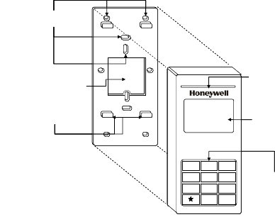
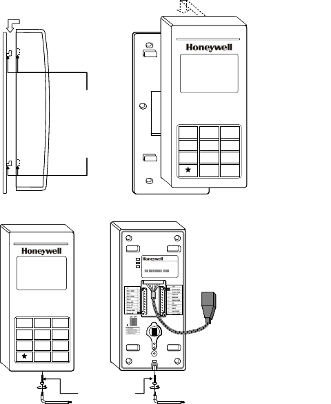
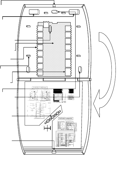
1. Fig.1 and Fig.2 show the parts of the
IdentIPoint reader. Use the back-plate of
the reader to mark out the position of the
reader on the drywall. Mark the positions of
the mounting screws and the opening for
routing the cables.
2. Cut the cable opening on the drywall using
suitable tools and punch an adequate
number of holes for the mounting screws. It
is advisable to use at least four screws for
fixing the reader. Use the wall anchors for
additional holding strength. See Fig.3.
3. Hold the back-plate in position on the
drywall. Align the mounting screws with
their holes and fasten the back-plate
securely on the drywall using the screws.
See Fig.3.
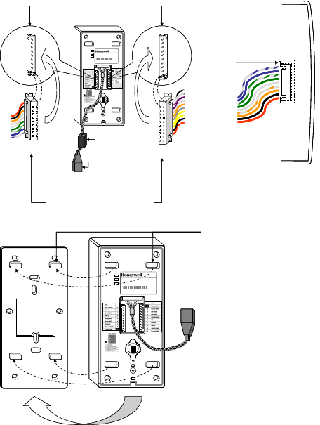
4. Route the field wires including the Ethernet
cable (if required) from behind the drywall
through the cable opening and bring them
to the front of the mounting surface. Clip
the square ferrite clip on the reader’s
Ethernet pigtail. See Fig.6. Connect the
field wiring to the correct Molex pigtails.
See Fig.5. For reader connection details
see Fig.10. Plug the Molex terminal(s) in
ports J9 and J10 at the back of the reader.
See Fig.6. Clip (with two turns wrapped)
the round ferrite clip on the field Ethernet
cable. See Fig.5. Plug the RJ45 connector
of the field Ethernet cable into the Ethernet
port of the reader at the end of the pigtail.
See Fig.6. Drop the excess lengths of
Molex and Ethernet wires behind the
drywall. Set the S1 DIP switch if the reader
is to be connected to an IOM via RS485.
See Fig.10 and appendix for more details.
5. Once all the connections and settings are
done, hold the reader against the back-
plate, aligning the mounting slots at the
back of the reader with their corresponding
catches on the back-plate and push it
downwards until it hooks into place firmly.
See Fig.7 and Fig.8.
6. Use the Allen wrench to tighten the tamper-
resistant screw at the bottom of the reader.
See Fig.9.
Gang-box (concrete wall) Mounting
1. Fig.1 and Fig.2 show the parts of the
IdentIPoint reader. Ensure that the correct
sized gang-box is securely embedded in
the concrete wall. The holes provided in the
gang-box for the screws should align
properly with at least two of the holes
provided in the reader back-plate for the
screws.
2. Hold the back-plate in position over the
gang-box. Align the mounting screws with
their holes and fasten the back-plate
securely on the gang-box using the screws.
See Fig.4.
95-7771
3
Honeywell IdentIPoint Intelligent Smartcard Readers
3. Route the field wiring including the Ethernet
cable (if required) from the conduits into the
gang-box. Clip the square ferrite clip on the
reader’s Ethernet pigtail. See Fig.6.
Connect the field wiring to the correct
Molex pigtails. See Fig.5. For reader
connection details see Fig.10. Route the
Molex terminal(s) through the cable
opening on the back-plate towards the front
of the mounting surface (see Fig.5) and
plug them in ports J9 and J10 at the back
of the reader. See Fig.6. Clip (with two
turns wrapped) the round ferrite clip on the
field Ethernet cable. See Fig.5. Plug the
RJ45 connector of the field Ethernet cable
into the Ethernet port of the reader
provided at the end of the pigtail.
Accommodate the Molex and Ethernet
pigtails inside the gang-box. Set the S1 DIP
switch if the reader is to be connected to an
IOM via RS485. See Fig.10 and appendix
for more details.
4. Once all the connections and settings are
done, hold the reader against the back-
plate, aligning the mounting slots at the
back of the reader with their corresponding
catches on the back-plate and push it
downwards until it hooks into place firmly.
See Fig.7 and Fig.8.
5. Use the Allen wrench to tighten the tamper-
resistant screw at the bottom of the reader.
See Fig.9.
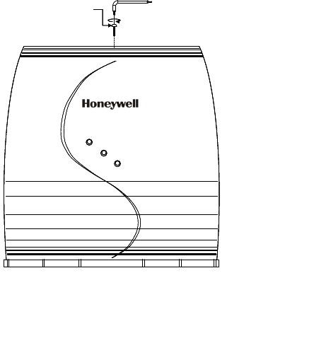
Fig.1. Parts of IdentIPoint
reader – Front of reader and
Back-
p
late
BACK-PLATE
CATCHES FOR
HOLDING READER
ON BACK-PLATE (4)
READER
STATUS LED
KEYPAD
READER FRONT
MOUNTING SCREW
HOLES (10)
OPENING FOR
ROUTING CABLES (1)
123
456
789
0#
LCD
BACK-PLATE
CATCHES FOR
HOLDING READER
ON BACK-PLATE (4)
READER
STATUS LED
KEYPAD
READER FRONT
MOUNTING SCREW
HOLES (10)
OPENING FOR
ROUTING CABLES (1)
LCD
123
456
789
0#
123
456
789
0#
95-7771
4
Honeywell IdentIPoint Intelligent Smartcard Readers
95-7771
5
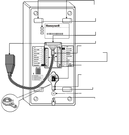
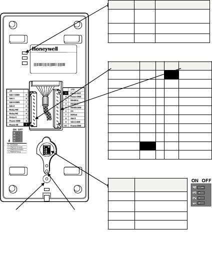
READER MOUNTING
SLOTS (4)
STATUS LEDS (3)
DIP SWITCH S1
READER BACK
10/100
Activity
Power
ETHERNET TERMINAL
(EPOXY POTTED FOR
IP65 COMPLIANCE)
FACTORY RESET
SWITCH
OPTICAL TAMPER
SENSOR
WIRING
TERMINAL
PORTS J9, J10
HOLE FOR TAMPER-
RESISTANT SCREW
CAT5 PIGTAIL
HOLE FOR HOLDING
RUBBER COVER
(SHOWN IN CALLOUT)
RJ45 TERMINAL PLUG
Model: BTSTD
IdentIPoint Standard Indoor
Power 10-28 VDC, PoE
MAC ID Eth ernet 0 040840AF33E
MAC ID Wi-fi 00408-IOAF33F
Manufactured: 2009 .07.13 MADE IN CHINA
1
2
3
4
1
2
3
4
ON POSITIONON POSITION
READER MOUNTING
SLOTS (4)
STATUS LEDS (3)
DIP SWITCH S1
READER BACK
10/100
Activity
Power
ETHERNET TERMINAL
(EPOXY POTTED FOR
IP65 COMPLIANCE)
FACTORY RESET
SWITCH
OPTICAL TAMPER
SENSOR
WIRING
TERMINAL
PORTS J9, J10
HOLE FOR TAMPER-
RESISTANT SCREW
CAT5 PIGTAIL
HOLE FOR HOLDING
RUBBER COVER
(SHOWN IN CALLOUT)
RJ45 TERMINAL PLUG
Model: BTSTD
IdentIPoint Standard Indoor
Power 10-28 VDC, PoE
MAC ID Eth ernet 0 040840AF33E
MAC ID Wi-fi 00408-IOAF33F
Manufactured: 2009 .07.13 MADE IN CHINA
1
2
3
4
1
2
3
41
2
3
4
1
2
3
4
1
2
3
4
ON POSITIONON POSITIONON POSITIONON POSITION
Fig.2. Parts of IdentIPoint reader – Back of reader
Honeywell IdentIPoint Intelligent Smartcard Readers
95-7771
6
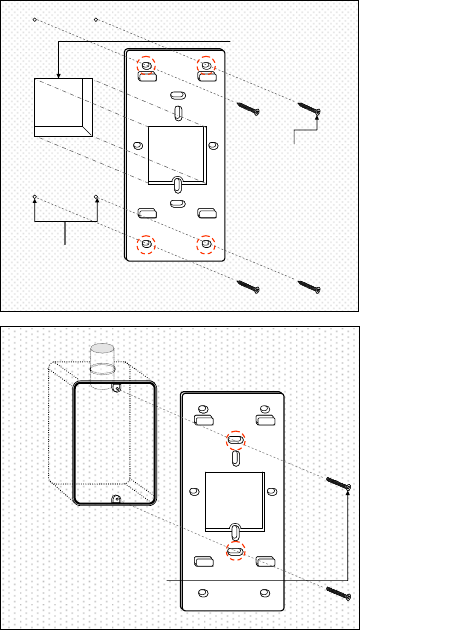
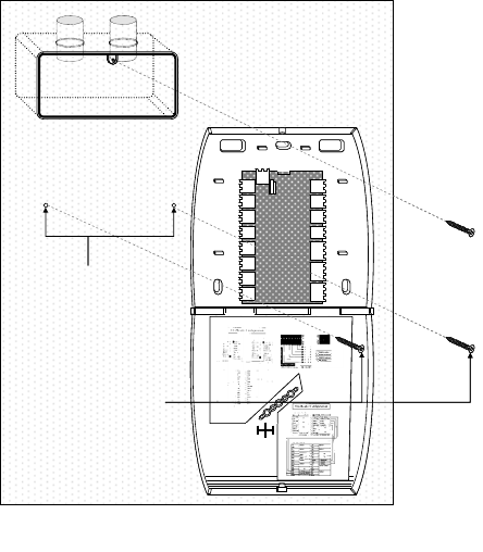
Fig.4. Fixing
reader back-
plate to
concrete wall
USE THE SCREWS PROVIDED
TO FIX THE READER BACK-
PLATE TO THE EMBEDDED
GANGBOX.
NOTE: USE A MINIMUM OF 2
SCREWS IN THE HOLES
CIRCLED IN RED TO FASTEN
THE BACK-PLATE
GANGBOX EMBEDDED IN WALL
USE THE SCREWS PROVIDED
TO FIX THE READER BACK-
PLATE TO THE EMBEDDED
GANGBOX.
NOTE: USE A MINIMUM OF 2
SCREWS IN THE HOLES
CIRCLED IN RED TO FASTEN
THE BACK-PLATE
GANGBOX EMBEDDED IN WALL
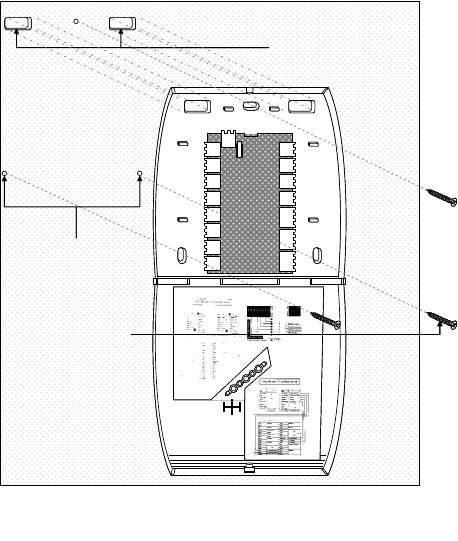
Fig.3. Fixing
reader back-
plate to
drywall
USE THE SCREWS PROVIDED
TO FIX THE BACK-PLATE TO
THE DRYWALL.
NOTE: USE A MINIMUM OF 4
SCREWS IN THE HOLES
CIRCLED IN RED
CUT AN OPENING IN THE
DRYWALL FOR ROUTING THE
WIRES. THE OPENING MUST
HAVE THE SAME DIMENSIONS
AS THAT IN THE BACK-PLATE.
PUNCH AN ADEQUATE NUMBER
OF HOLES IN THE DRYWALL
FOR THE SCREWS
Honeywell IdentIPoint Intelligent Smartcard Readers
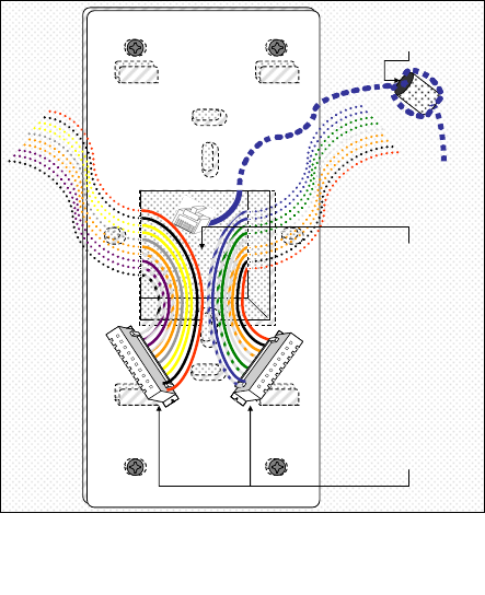
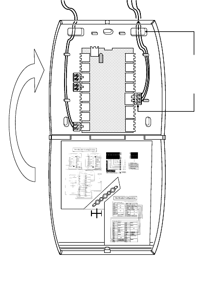
ROUTE THE RJ45 CONNECTOR
(IF REQUIRED) AND MOLEX
TERMINALS FROM BEHIND THE
DRYWALL OR THROUGH THE
CONDUITS (IN CASE OF
CONCRETE WALL) AND BRING
THEM TOWARDS THE FRONT
SIDE OF THE MOUNTING
SURFACE THROUGH THE
OPENING ON THE READER’S
BACK-PLATE.
PLUG THE RJ45 CONNECTOR
INTO THE ETHERNET PORT OF
THE READER AT THE END OF
THE PIGTAIL.
PLUG THE MOLEX TERMINALS
INTO THE J9 AND J10 PORTS
OF THE READER
CLIP ROUND FERRITE CLIP ON
THE FIELD ETHERNET CABLE
WITH TWO TURNS WRAPPED
Fig.5. Routing the wires before plugging the connectors
into the reader
95-7771
7
Honeywell IdentIPoint Intelligent Smartcard Readers
HOLD THE 9 AND 10-PIN
MOLEX TERMINALS
PERPENDICULAR TO THE
BACK OF THE READER AND
ALIGN THEM CORRECTLY
WITH PORTS J9 AND J10
PUSH THE 9 AND 10-PIN MOLEX TERMINALS
FIRMLY INTO THE READER PORTS J9 AND J10
RESPECTIVELY. ENSURE THAT ALL 9 AND 10
PINS GO INSIDE THE HOLES OF THEIR
RESPECTIVE TERMINALS AND THAT THE
SPECIAL PROTRUSIONS ON THE TERMINALS
MATE WITH THE SPECIAL SLOTS PROVIDED
ON THE PORTS. THIS ENSURES THAT THE
TERMINALS CANNOT BE PLUGGED INTO
WRONG PORTS.
PLUG RJ45
CONNECTOR (IF
REQD.) IN THE RJ45
TERMINAL PLUG
PIN 9
PIN 1
PORT
J9
PIN 1
PIN 10
PORT
J10
10/100
Activity
Power
TO PIN 9
TO PIN 1
9-PIN MOLEX
TERMINAL 10-PIN MOLEX
TERMINAL
TO PIN 1
TO PIN 10
Model: BTSTD
IdentIPoint S tandar d Indoor
Power 10-28 VDC, PoE
MAC ID Etherne t 004 0840AF 33E
MAC ID Wi-fi 004 08-IOAF33 F
Manufactured: 2009.0 7.13 MA DE IN CHINA
ON POSITIONON POSITIONON POSITIONON POSITION
1
2
3
41
2
3
41
2
3
41
2
3
4
1
2
3
4
CLIP SQUARE
FERRITE CLIP TO
THE PIGTAIL
BOTH MOLEX TERMINALS
SHOULD FIT FIRMLY INSIDE
THEIR RESPECTIVE PORTS
AT THE BACK OF THE
READER AS SHOWN
BOTH MOLEX TERMINALS
SHOULD FIT FIRMLY INSIDE
THEIR RESPECTIVE PORTS
AT THE BACK OF THE
READER AS SHOWN
Fig.6. Plugging the
connectors into the
IdentIPoint reade
r
ALIGN THE MOUNTING
SLOTS BEHIND THE
READER WITH THEIR
CORRESPONDING
CATCHES ON THE
BACK-PLATE
10/100
Activity
Power
Model: BTSTD
IdentIP oint Stan dard Indoo r
Power 10-28 VDC, PoE
MAC ID Ethernet 0040840AF33E
MAC ID Wi- fi 00408- IOAF3 3F
Manufactured: 2009.07 .13 MADE IN CHINA
ON POSITIONON POSITIONON POSITIONON POSITION
1
2
3
4
1
2
3
41
2
3
4
1
2
3
4
1
2
3
4
Fig.7. Aligning IdentIPoint
reader with back-plate
before fixing it
95-7771
8
Honeywell IdentIPoint Intelligent Smartcard Readers
READER ASSEMBLY –
SIDE VIEW
ALIGN THE MOUNTING
SLOTS BEHIND THE
READER WITH THEIR
CORRESPONDING
CATCHES ON THE
BACK-PLATE. PUSH
THE READER
DOWNWARDS UNTIL IT
HOOKS INTO PLACE
FIRMLY
123
456
789
0 #
123
456
789
0 #
READER ASSEMBLY –
FRONT VIEW
READER ASSEMBLY –
SIDE VIEW
ALIGN THE MOUNTING
SLOTS BEHIND THE
READER WITH THEIR
CORRESPONDING
CATCHES ON THE
BACK-PLATE. PUSH
THE READER
DOWNWARDS UNTIL IT
HOOKS INTO PLACE
FIRMLY
123
456
789
0 #
123
456
789
0 #
READER ASSEMBLY –
FRONT VIEW
Fig.8. Fixing
the
IdentIPoint
reader on the
back-plate
10/100
Activity
Power
Model: BTSTD
IdentIPoint S tandard Indoor
Power 10-28 VDC, PoE
MAC ID Ethernet 0040840AF33E
MAC ID Wi-fi 00408-IOAF33F
Manufactured: 2009.07.13 MADE IN CHINA
ON POSITIONON POSITIONON POSITIONON POSITION
1
2
3
4
1
2
3
41
2
3
4
1
2
3
4
1
2
3
4
USE THE ALLEN
WRENCH TO
SECURE THE
READER TO THE
BACK-PLATE WITH
THE TAMPER-
RESISTANT SCREW
123
456
789
0#
123
456
789
0#
123
456
789
0#
123
456
789
0#
Fig.9.
Securing the
IdentIPoint
reader to the
back-plate
95-7771
9
Honeywell IdentIPoint Intelligent Smartcard Readers
10/100
Activity
Power
Model: BTSTD
IdentIPoint Standard Indoor
Power 10-28 VDC, PoE
MAC ID Ethernet 0040840AF33E
MAC ID Wi-fi 00408-IOAF33F
Manufactured: 2009.07.13 MADE IN CHINA
ON POSITIONON POSITIONON POSITIONON POSITION
1
2
3
4
1
2
3
41
2
3
4
1
2
3
4
1
2
3
4
10/100
Activity
Power
Model: BTSTD
IdentIPoint Standard Indoor
Power 10-28 VDC, PoE
MAC ID Ethernet 0040840AF33E
MAC ID Wi-fi 00408-IOAF33F
Manufactured: 2009.07.13 MADE IN CHINA
ON POSITIONON POSITIONON POSITIONON POSITION
1
2
3
4
1
2
3
41
2
3
4
1
2
3
4
1
2
3
4
Marking Color Description
10/100 Green Onwhennetworkis100
MBit
Activity Orange Flashesonnetworkactivity
Power Blue Onifpoweron
Marking Color Description
10/100 Green Onwhennetworkis100
MBit
Activity Orange Flashesonnetworkactivity
Power Blue Onifpoweron
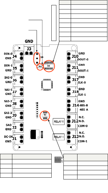
J9 PIN PIN J10
SAI‐1‐GND 91Power‐OUT
SAI‐182Power‐GND
SAI‐0‐GND 7 3 RS485‐A
SAI‐064RS485‐B
Relay‐NO 5 5 RS485‐GND
Relay‐NC 4 6 DO
Relay‐C37DOGnd
Power‐GND 2 8 SAI‐2
Power‐IN 19SAI‐2‐GND
10 Frame‐GND
J9 PIN PIN J10
SAI‐1‐GND 91Power‐OUT
SAI‐182Power‐GND
SAI‐0‐GND 7 3 RS485‐A
SAI‐064RS485‐B
Relay‐NO 5 5 RS485‐GND
Relay‐NC 4 6 DO
Relay‐C37DOGnd
Power‐GND 2 8 SAI‐2
Power‐IN 19SAI‐2‐GND
10 Frame‐GND
Position Effectwhen“ON”
(PositionLeft)
1RS485‐Apullup
2RS485termination
3RS485‐Bpulldown
4WifiDisable
Position Effectwhen“ON”
(PositionLeft)
1RS485‐Apullup
2RS485termination
3RS485‐Bpulldown
4WifiDisable
DIP SWITCH S1
CONNECTORS AT THE BACK
LED INDICATORS AT THE BACK
FACTORY
RESET
SWITCH
OPTICAL
ALARM
TAMPER
Fig10. Reader connections
95-7771
10
Honeywell IdentIPoint Intelligent Smartcard Readers
95-7771
11
INPUT/OUTPUT MODULE
Drywall Mounting
1. The IOM is a clamshell plastic case. The
back half of the case has the electronic
circuit board fastened to it while the front
case cover swings open to allow access to
the electronics and wiring. Pull open the
front cover. This reveals the mounting
holes and other components inside the
IOM. See Fig.11 and Fig.12.
2. Use the back half to mark out the position
of the IOM on the drywall. Also mark the
positions of the mounting screws and the
openings for routing the cables. See Fig.13.
3. Cut the two cable openings on the drywall
using suitable tools. The openings should
be aligned with the knock-out holes
provided on the back half for routing the
cables. Also punch three holes at suitable
places in the drywall for the mounting
screws. Use the wall anchors for additional
holding strength. See Fig.13.
4. Ensure that the knock-out holes on the
back half have been opened up. (Knock-
out holes are also provided on both sides
of the IOM enclosure in case field
conditions require routing the wires from
the sides.) Hold the back half in position on
the drywall. Align the mounting screws with
their holes and fasten the back half
securely on the drywall using the three
screws. See Fig.13.
5. Route the field wires from behind the
drywall through the cable opening and
bring them inside the IOM via the knock-out
holes. Connect the wire terminals to the
ends of the wires and plug the wire
terminal(s) in their correct slots on the PCB.
See Fig.15. For IOM connection details
see Fig.17. Drop the excess wire lengths
behind the drywall. Set the S1 DIP switch if
the IOM is to be connected to a reader via
RS485. See Fig.17 and appendix for more
details.
6. Set the IOM address as per Fig.17 and
appendix. Once all connections and
settings are done, close the IOM enclosure
by pressing the front case cover over the
back half. See Fig.15.
7. Use the Allen wrench to tighten the tamper-
resistant screw at the top of the IOM
enclosure. See Fig.16.
Gang-box (concrete wall) Mounting
1. The IOM is a clamshell plastic case. The
back half of the case has the electronic
circuit board fastened to it while the front
case cover swings open to allow access to
the electronics and wiring. Pull open the
front cover. This reveals the mounting
holes and other components inside the
IOM. See Fig.11 and Fig.12.
2. Ensure that the correct sized gang-box is
securely embedded in the concrete wall.
One of the holes provided in the gang-box
for the screws should align properly with at
least the top hole provided in the IOM's
back half for the screw. For the remaining
screws punch additional holes at the
correct places directly in the concrete wall.
Use the wall anchors for additional holding
strength. The gang-box itself should be
large enough to cover both the knock-out
cable holes at the back of the IOM. See
Fig.14.
Honeywell IdentIPoint Intelligent Smartcard Readers
3. Route the field wires from the conduits into
the gang-box and bring them inside the
IOM via the knock-out holes.
4. The IOM can now be mounted on the wall.
Hold the back half in position over the
gang-box and wall. Align the three
mounting screws with their holes and
fasten the back half securely on the gang-
box and wall using the screws. See Fig.14.
5. Connect the wire terminals to the ends of
the wires and plug the wire terminal(s) in
their correct slots on the PCB. See Fig.15.
For IOM connection details see Fig.17.
Accommodate any excess wire lengths
inside the gang-box. Set the S1 DIP switch
if the IOM is to be connected to a reader
via RS485. See Fig.17 and appendix for
more details.
6. Set the IOM address as per Fig.17 and
appendix. Once all connections and
settings are done, close the IOM enclosure
by pressing the front case cover over the
back half. See Fig.15.
7. Use the Allen wrench to tighten the tamper-
resistant screw at the top of the IOM
enclosure. See Fig.16.
95-7771
12
Honeywell IdentIPoint Intelligent Smartcard Readers
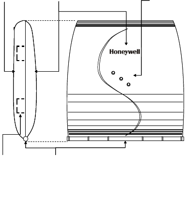
Power
Data
Tamper
POWER,
DATA AND
TAMPER
INDICATION
LEDS
FRONT COVER
OF THE IOM
HINGE AT THE
BOTTOM HOLDING
THE TWO PARTS
TOGETHER
BACK HALF OF
THE IOM
SIDE KNOCK-OUTS
FOR CABLE HOLES
Power
Data
Tamper
POWER,
DATA AND
TAMPER
INDICATION
LEDS
FRONT COVER
OF THE IOM
HINGE AT THE
BOTTOM HOLDING
THE TWO PARTS
TOGETHER
BACK HALF OF
THE IOM
SIDE KNOCK-OUTS
FOR CABLE HOLES
Fig.11. Outer structure of IOM – Front and side view
95-7771
13
Honeywell IdentIPoint Intelligent Smartcard Readers
PRINTED CIRCUIT
BOARD
BACK KNOCK-
OUTS FOR CABLE
HOLES (2)
WIRING
TERMINALS –
2 WIRE (13)
WIRING
TERMINALS –
3 WIRE (3)
IOM FRONT COVER - OPEN
HOLE FOR
TAMPER-
RESISTANT
SCREW
IOM BACK HALF - OPEN
HOLE FOR
TAMPER-
RESISTANT
SCREW
LIGHT GUIDES
CABLE
GUIDES (6)
COVER TAMPER
DETECTION
SWITCH
PULL OPEN THE
FRONT COVER OF
THE IOM AND ALLOW
IT TO HANG FROM
THE HINGE
MOUNTING
SCREW HOLES
(3)
Fig.12. Internal structure and components of IOM
95-7771
14
Honeywell IdentIPoint Intelligent Smartcard Readers
95-7771
15
Fig.13. Fixing the IOM on a drywall
CUT OPENINGS IN THE
DRYWALL FOR ROUTING THE
WIRES. THE OPENINGS MUST
HAVE THE SAME DIMENSIONS
AS THAT IN THE BACK HALF OF
THE IOM.
Fig.13. Fixing the IOM on a drywall
USE THE SCREWS
PROVIDED TO FIX THE
BACK HALF OF THE IOM
TO THE DRYWALL.
NOTE: USE ALL THREE
HOLES TO FASTEN THE
IOM
PUNCH THREE HOLES IN
THE DRYWALL FOR THE
SCREWS
CUT OPENINGS IN THE
DRYWALL FOR ROUTING THE
WIRES. THE OPENINGS MUST
HAVE THE SAME DIMENSIONS
AS THAT IN THE BACK HALF OF
THE IOM.
USE THE SCREWS
PROVIDED TO FIX THE
BACK HALF OF THE IOM
TO THE DRYWALL.
NOTE: USE ALL THREE
HOLES TO FASTEN THE
IOM
PUNCH THREE HOLES IN
THE DRYWALL FOR THE
SCREWS
Honeywell IdentIPoint Intelligent Smartcard Readers
USE THE SCREWS PROVIDED
TO FIX THE BACK HALF OF IOM
TO THE GANGBOX AND THE
WALL.
NOTE: USE ALL 3 SCREWS TO
FASTEN THE IOM
GANGBOX EMBEDDED IN WALL
PUNCH ADDITIONAL HOLES
IN THE WALL FOR THE
OTHER SCREWS
USE THE SCREWS PROVIDED
TO FIX THE BACK HALF OF IOM
TO THE GANGBOX AND THE
WALL.
NOTE: USE ALL 3 SCREWS TO
FASTEN THE IOM
GANGBOX EMBEDDED IN WALL
PUNCH ADDITIONAL HOLES
IN THE WALL FOR THE
OTHER SCREWS
Fig.14. Fixing the IOM on a concrete wall using gang-box and conduit
95-7771
16
Honeywell IdentIPoint Intelligent Smartcard Readers
95-7771
17
Fig.15. Routing the wires and connecting them to the IOM PCB
ROUTE THE WIRES
THROUGH THE
KNOCKED OUT HOLES
AND FIX THEM TO THE
CORRECT TERMINALS
ON THE PCB USING THE
PROVIDED WIRE
TERMINAL BLOCKS
AFTER WIRING AND
OTHER HARDWARE
CONFIGURATIONS ARE
DONE, SHUT THE FRONT
COVER OF THE IOM
ROUTE THE WIRES
THROUGH THE
KNOCKED OUT HOLES
AND FIX THEM TO THE
CORRECT TERMINALS
ON THE PCB USING THE
PROVIDED WIRE
TERMINAL BLOCKS
AFTER WIRING AND
OTHER HARDWARE
CONFIGURATIONS ARE
DONE, SHUT THE FRONT
COVER OF THE IOM
AFTER WIRING AND
OTHER HARDWARE
CONFIGURATIONS ARE
DONE, SHUT THE FRONT
COVER OF THE IOM
Honeywell IdentIPoint Intelligent Smartcard Readers
95-7771
18
Power
Data
Tamper
USE THE ALLEN
WRENCH TO
SECURE THE FRONT
COVER OF THE IOM
TO THE BACK HALF
WITH TAMPER-
RESISTANT SCREW
Power
Data
Tamper
Power
Data
Tamper
USE THE ALLEN
WRENCH TO
SECURE THE FRONT
COVER OF THE IOM
TO THE BACK HALF
WITH TAMPER-
RESISTANT SCREW
Fig.16. Securing the front cover onto the back half of the IOM
Honeywell IdentIPoint Intelligent Smartcard Readers
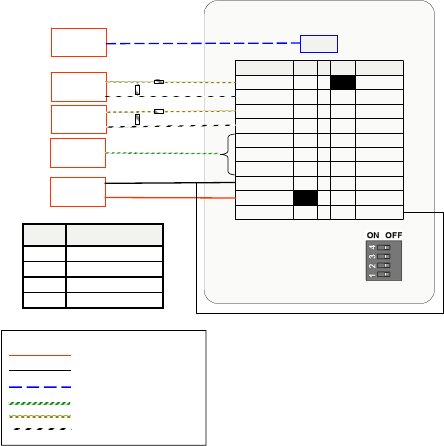
DIPswitch‐ S1
Position Effectwhen“ON”
(PositionUp)
1RS485‐Apullup
2RS485termination
3RS485‐Bpulldown
4Reserve
Position Effectwhen“ON”
(PositionUp)
1RS485‐Apullup
2RS485termination
3RS485‐Bpulldown
4Reserve
Switch Description
S1 RS485TerminationControlDIPswitch
S2 InitializationButton
S3 IOMAddresssetupDIPswitch
S4 Covertamperdetectionswitch
Switch Description
S1 RS485TerminationControlDIPswitch
S2 InitializationButton
S3 IOMAddresssetupDIPswitch
S4 Covertamperdetectionswitch
S2:Initialization
Button
DIPswitchS3 ‐IOMaddress
Position Description
1 Addressvalue1
2 Addressvalue2
3 Addressvalue4
4 Addressvalue8
5 Addressvalue16
6 Addressvalue32
7 Addressvalue64
8ForIOMsetup,normallysettoOFF
Position Description
1 Addressvalue1
2 Addressvalue2
3 Addressvalue4
4 Addressvalue8
5 Addressvalue16
6 Addressvalue32
7 Addressvalue64
8ForIOMsetup,normallysettoOFF
S4:Covertamper
detectionswitch
Fig.17. IOM connections
95-7771
19
Honeywell IdentIPoint Intelligent Smartcard Readers
APPENDIX
WIRING DIAGRAMS
Fig.18. Single reader with
REX and without IOM
Power – Min . 18 AW G
Power Gnd –Min. 18 AWG
Eth ern et – CAT5
Power/Signal – Min. 18 AWG
Signal –Min. 18 AWG
Signal –Min. 18 AWG
LEGEND
Position Effect “O
to
RS485
when
th
N”
ht)
llup
(slideeRig
1‐
RS485
Apu
term
‐
2 RS485 ination
Bpulldown 3
4WifiDisable
DC–Power
12to24V
IfPOEisnotused
2KΩ
ToDoorSensor
1KΩ
1
Power‐OUT
SAI‐1‐GND
9
2
Power‐GND
SAI‐1
8
3
RS485‐A
SAI‐0‐GND
7
4
RS485‐B
SAI‐0
6
5RS485‐GND
Relay‐NO 5
6
DO
Relay‐NC
4
7
DOGnd
Relay‐C
3
8
SAI‐2
Power‐GND
2
9
SAI‐2‐GND
Power‐IN
1
Frame‐GND
J10PINPINJ9
S1
ToDoorLockToDoorLock
ToLANToLAN Ethernet
ToREXSwitchToREXSwitch
2KΩ1KΩ
IdentIPointreader
10
95-7771
20
Honeywell IdentIPoint Intelligent Smartcard Readers
Ethernet
ToDoorLock
ToLAN
IdentIPointReader
DI‐0GND
GND DO‐0
DI‐1GND
GND D1‐0
SAI‐0GND
GND ILK‐0
SAI‐1GND
GND ILK‐1
SAI‐2485‐
GND
GND 485‐B
SAI‐3485‐A
GND N.C
SAO N.O
GND RLO‐C
12V N.C
GND N.O
FGND RL1‐C
DI‐0GND
GND DO‐0
DI‐1GND
GND D1‐0
SAI‐0GND
GND ILK‐0
SAI‐1GND
GND ILK‐1
SAI‐2485‐
GND
GND 485‐B
SAI‐3485‐A
GND N.C
SAO N.O
GND RLO‐C
12V N.C
GND N.O
FGND RL1‐C
IOmodule
SeparatePowerSupply
canalsobeusedforIOM
1KΩ
2KΩ
ToREXSwitch
1KΩ
2KΩ
ToDoorSensor
S1
S1
1
Power‐OUT
SAI‐1‐GND
9
2
Power‐GND
SAI‐1
8
3
RS485‐A
SAI‐0‐GND
7
4
RS485‐B
SAI‐0
6
5RS485‐GND
Relay‐NO 5
6
DO
Relay‐NC
4
7
DOGnd
Relay‐C
3
8
SAI‐2
Power‐GND
2
9
SAI‐2‐GND
Power‐IN
1
Frame‐GND
J10PINPINJ9
10
DC–Power
12to24V
IfPOEisnotused
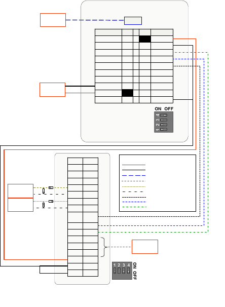
Signal/Power – Min. 18 AWG
Power – Min. 18 AWG
Power Gnd – Min. 18 AWG
Ethernet – CAT5
Signal – Min. 18 AWG
Signal – Min. 18 AWG
Comm. – Min. 18 AWG
Comm. – Min. 18 AWG
Comm. – Min. 18 AWG
LEGEND
Signal/Power – Min. 18 AWG
Power – Min. 18 AWG
Power Gnd – Min. 18 AWG
Ethernet – CAT5
Signal – Min. 18 AWG
Signal – Min. 18 AWG
Comm. – Min. 18 AWG
Comm. – Min. 18 AWG
Comm. – Min. 18 AWG
LEGEND
Fig.19. Single reader with REX and IOM (S1 DIP switch settings shown)
95-7771
21
Honeywell IdentIPoint Intelligent Smartcard Readers
95-7771
22
Ethernet
Ident IPointReader
GND
12V
GND
SAO
GND
SAI‐3
GND
SAI‐2
GND
SAI‐1
GND
SAI‐0
GND
GND
GND
12V
GND
SAO
GND
SAI‐3
GND
SAI‐2
GND
SAI‐1
GND
SAI‐0
GND
DI‐1
GND
DI‐0
IOm
o
ToDoorSensor 1KΩ
2KΩ
ConnectionsonINside
DC–Power
12to24V
IfPOEisnotused
DC–Power
12to24V
IfPOEisnotused
1
Power‐OUT
SAI‐1‐GND
9
2
Power‐GND
SAI‐1
8
3
RS485‐A
SAI‐0‐GND
7
4
RS485‐B
SAI‐0
6
5RS485‐GND
Relay‐NO 5
6
DO
Relay‐NC
4
7
DOGnd
Relay‐C
3
8
SAI‐2
Power‐GND
2
9
SAI‐2‐GND
Power‐IN
1
Frame‐GND
J10PINPINJ9
10
1
Power‐OUT
SAI‐1‐GND
9
2
Power‐GND
SAI‐1
8
3
RS485‐A
SAI‐0‐GND
7
4
RS485‐B
SAI‐0
6
5RS485‐GND
Relay‐NO 5
6
DO
Relay‐NC
4
7
DOGnd
Relay‐C
3
8
SAI‐2
Power‐GND
2
9
SAI‐2‐GND
Power‐IN
1
Frame‐GND
J10PINPINJ9
10
FGND
Po wer – Min. 1 8 AWG
Po wer Gnd – Min. 18 AWG
CAT5
Sig nal/Power – Min. 18 AWG
Sig n al – Min . 18 AWG
Sig n al – Min . 18 AWG
Co mm. – Min. 18 AWG
Co mm. – Min. 18 AWG
Co mm. – Min. 18 AWG
Po wer – Mi n. 18 AWG
Po wer Gnd – Min. 18 AWG
Co mm. – Min . 18 AWG
LEGEND
Co mm. – Min . 18 AWG
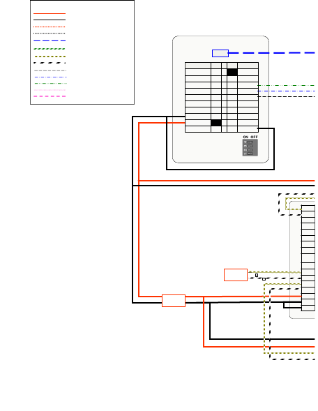
S1
Note: For Dual Reader setup the Door
Sensor (Connection to IN Reader) is
always connected to SAI3.
* This drawing
continues on the
opposite page
Fig.20. Two readers with IOM (S1 DIP switch settings shown)
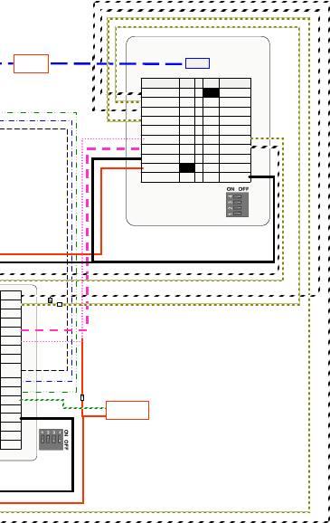
Honeywell IdentIPoint Intelligent Smartcard Readers
Ethernet
IdentIPointRead er
ToLAN
RL1‐C
N.O
N.C
RLO‐C
N.O
N.C
485‐A
485‐B
485‐
GND
ILK‐1
GND
ILK‐0
GND
D1‐0
GND
DO‐0
GND
RL1‐C
N.O
N.C
RLO‐C
N.O
N.C
485‐A
485‐B
485‐
GND
ILK‐1
GND
ILK‐0
GND
D1‐0
GND
DO‐0
GND
o
dule
ConnectionsonOUTside
1
Power‐OUT
SAI‐1‐GND
9
2
Power‐GND
SAI‐1
8
3
RS485‐A
SAI‐0‐GND
7
4
RS485‐B
SAI‐0
6
5RS485‐GND
Relay‐NO 5
6
DO
Relay‐NC
4
7
DOGnd
Relay‐C
3
8
SAI‐2
Power‐GND
2
9
SAI‐2‐GND
Power‐IN
1
Frame‐GND
J10PINPINJ9
10
1
Power‐OUT
SAI‐1‐GND
9
2
Power‐GND
SAI‐1
8
3
RS485‐A
SAI‐0‐GND
7
4
RS485‐B
SAI‐0
6
5RS485‐GND
Relay‐NO 5
6
DO
Relay‐NC
4
7
DOGnd
Relay‐C
3
8
SAI‐2
Power‐GND
2
9
SAI‐2‐GND
Power‐IN
1
Frame‐GND
J10PINPINJ9
10
2KΩ2KΩ
1KΩ
1KΩ
ToEMLDoorLock
S1
S1
95-7771
23
Honeywell IdentIPoint Intelligent Smartcard Readers
DC–Power
12to24V
IfPOEisnotused
RL1‐C
N.OGND
N.C12V
RLO‐CGND
N.OSAO
N.CGND
485‐ASAI‐3
485‐BGND
485‐
GND
SAI‐2
ILK‐1GND
GNDSAI‐1
ILK‐0GND
GNDSAI‐0
D1‐0GND
GNDDI‐1
DO‐0GND
GNDDI‐0
RL1‐C
N.OGND
N.C12V
RLO‐CGND
N.OSAO
N.CGND
485‐ASAI‐3
485‐BGND
485‐
GND
SAI‐2
ILK‐1GND
GNDSAI‐1
ILK‐0GND
GNDSAI‐0
D1‐0GND
GNDDI‐1
DO‐0GND
GNDDI‐0
IOmodule
RL1‐C
N.OGND
N.C12V
RLO‐CGND
N.OSAO
N.CGND
485‐ASAI‐3
485‐BGND
485‐
GND
SAI‐2
ILK‐1GND
GNDSAI‐1
ILK‐0GND
GNDSAI‐0
D1‐0GND
GNDDI‐1
DO‐0GND
GNDDI‐0
RL1‐C
N.OGND
N.C12V
RLO‐CGND
N.OSAO
N.CGND
485‐ASAI‐3
485‐BGND
485‐
GND
SAI‐2
ILK‐1GND
GNDSAI‐1
ILK‐0GND
GNDSAI‐0
D1‐0GND
GNDDI‐1
DO‐0GND
GNDDI‐0
IOmodule
DC–Power
12to24V
DC–Power
12to24V
DC–Power
12to24V
IOM 1 IOM 2 IOM 3
1Power‐OUT
SAI‐1‐GND92Power‐GND
SAI‐183RS485‐A
SAI‐0‐GND74RS485‐B
SAI‐065RS485‐GND
Relay‐NO56DO
Relay‐NC47DOGnd
Relay‐C38SAI‐2
Power‐GND29SAI‐2‐GND
Power‐IN
1
10Frame‐GND
J9PINPINJ10
Ethernet
BOTACreader
S1
1
2
3
4
OFFON
1Power‐OUT
SAI‐1‐GND92Power‐GND
SAI‐183RS485‐A
SAI‐0‐GND74RS485‐B
SAI‐065RS485‐GND
Relay‐NO56DO
Relay‐NC47DOGnd
Relay‐C38SAI‐2
Power‐GND29SAI‐2‐GND
Power‐IN
1
10Frame‐GND
J9PINPINJ10
Ethernet
BOTACreader
S1
1
2
3
4
OFFON
IdentIPoint Reader
1
Power‐OUT
SAI‐1‐GND
9
2
Power‐GND
SAI‐1
8
3
RS485‐A
SAI‐0‐GND
7
4
RS485‐B
SAI‐0
6
5RS485‐GND
Relay‐NO 5
6
DO
Relay‐NC
4
7
DOGnd
Relay‐C
3
8
SAI‐2
Power‐GND
2
9
SAI‐2‐GND
Power‐IN
1
Frame‐GND
J10J9 PIN PIN
10
FGND FGND FGND
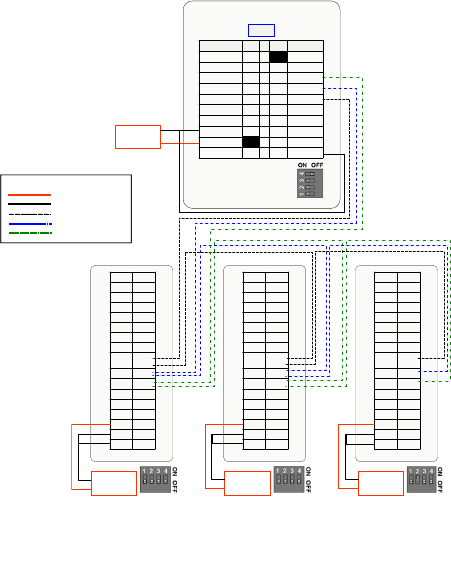
Po wer – Min . 18 AW G
Power Gnd –Min. 18 AWG
Comm. – Min. 18 AWG
Comm. – Min. 18 AWG
Comm. – Min. 18 AWG
LEGEND
S1
S1 S1 S1
Fig.21. Reader with three IOMs on a RS485 bus (S1 DIP switch settings
shown)
95-7771
24
Honeywell IdentIPoint Intelligent Smartcard Readers
95-7771
25
Power – Min . 18 AWG
Power Gnd –Min. 18 AWG
LEGEND
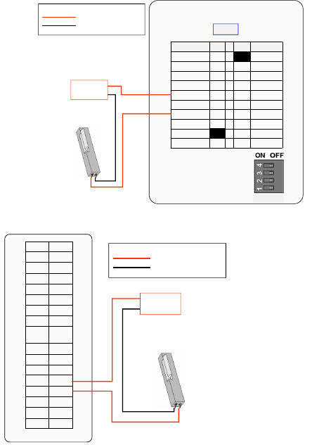
Fig.23. IOM and strike
latch
Power – Min. 18 AWG
Power Gn d – Min . 18 AWG
LEGEND
RL1‐C
N.OGND
N.C12V
RLO‐CGND
N.OSAO
N.CGND
485‐ASAI‐3
485‐BGND
485‐
GND
SAI‐2
ILK‐1GND
GNDSAI‐1
ILK‐0GND
GNDSAI‐0
D1‐0GND
GNDDI‐1
DO‐0GND
GNDDI‐0
IOmodule StrikeLatch
DC–Power
12VDC/24VDC
FGND
Fig.22. Reader and strike la
tch
StrikeLatch
Eth er net
IdentIPointReader
S1
1
2
3
4
OFFON
1
Power‐OUT
SAI‐1‐GND
9
2
Power‐GND
SAI‐1
8
3
RS485‐A
SAI‐0‐GND
7
4
RS485‐B
SAI‐0
6
5RS485‐GND
Relay‐NO 5
6
DO
Relay‐NC
4
7
DOGnd
Relay‐C
3
8
SAI‐2
Power‐GND
2
9
SAI‐2‐GND
Power‐IN
1
Frame‐GND
J10J9 PIN PIN
DC–Power
12VDC/24VDC
10
S1
Honeywell IdentIPoint Intelligent Smartcard Readers
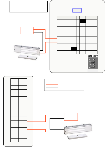
Fig.24. Reader and magnetic
lock
Po wer – Min. 18 AW G
Power Gn d – Min. 18 AWG
LEGEND
Ethernet
S1
1
2
3
4
OFFON
MagneticLock
IdentIPointReader
1
Power‐OUT
SAI‐1‐GND
9
2
Power‐GND
SAI‐1
8
3
RS485‐A
SAI‐0‐GND
7
4
RS485‐B
SAI‐0
6
5RS485‐GND
Relay‐NO 5
6
DO
Relay‐NC
4
7
DOGnd
Relay‐C
3
8
SAI‐2
Power‐GND
2
9
SAI‐2‐GND
Power‐IN
1
Frame‐GND
J10J9 PIN PIN
DC–Power
12VDC/24VDC
10
S1
Fig.25. IOM and magnetic
lock
Po wer – Mi n. 18 AW G
Power Gnd – Min. 18 AWG
LEGEND
RL1‐C
N.OGND
N.C12V
RLO‐CGND
N.OSAO
N.CGND
485‐ASAI‐3
485‐BGND
485‐
GND
SAI‐2
ILK‐1GND
GNDSAI‐1
ILK‐0GND
GNDSAI‐0
D1‐0GND
GNDDI‐1
DO‐0GND
GNDDI‐0
DC–Power
12VDC/24VDC
FGND
IOmodule MagneticLock
95-7771
26
Honeywell IdentIPoint Intelligent Smartcard Readers
95-7771
27
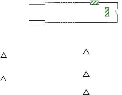
SAI-n
SAI-n GND
1KΩ
2KΩ
Sensor
Switch
SAI-n
SAI-n GND
1KΩ
2KΩ
Sensor
Switch
Fig.26. Supervisory Analog Inputs
Note:Doorsenseisconsideredopenwhensensorswitchisopen
11
22
33
EACHDOORSTRIKEREQUIRESA
14507020‐001DIODESUPPRESSION
NETWORK.DOORSTRIKEMAYDRAWA
MAXIMUMCURRENTOF2A;REGULATED12/24
VDC.DOORSTRIKEMUSTBEULLISTED.
EXITSWITCH:WIRINGMUSTBE
COMPLETEDWITHINTHEPROTECTED
AREAORNOTREADILYACCESSIBLEOUTSIDETHE
PROTECTEDAREA.
44
ALLWIRINGMUSTCONFORMTO
APPLICABLELOCALCODES,
ORDINANCES,ANDREGULATIONS
DOORCONTACTSMUSTBEULLISTED.
MAXIMUMWIRELENGTH500FT(152M).
WIRETYPE18AWG(0.8SQMM),50OHM60
mAMAXIMUM.
55
DONOTROUTECOMMUNICATION
WIRESWITHPOWERORLOCKING
DEVICES.
NOTE:FORCOMMUNICATIONCIRCUITSAND
OTHERAPPLICABLEWIRINGCIRCUITSWHERE
WIRINGENTERSANDEXITSTHEBUILDING,
REFERTOLIGHTNINGPROTECTORTABLEFOR
APPROPRIATELIGHTNINGPROTECTORUSAGE.
Honeywell IdentIPoint Intelligent Smartcard Readers
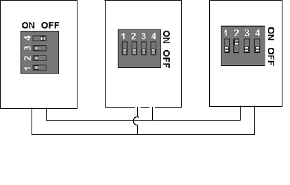
RS485 COMMUNICATION AND
TERMINATION SETTING
Both IdentIPoint readers and IOMs are
equipped with a termination circuit and
do not need an external termination
resistor. Setting the DIP switch 2 on S1
to ON introduces a termination resistor
on the RS485 line. The units that sit
physically on both ends of an RS485
bus should have their RS485
termination turned on. It is also
recommended to turn on the pull-up and
pull-down resistors in the IdentIPoint
reader (master).
Termination OFFTermination ON Termination ON
IOM (Slave 1)
Termination OFF
Reader (Master)
Termination ON
Pull-up ON
Pull-down ON
IOM (Slave 2)
Termination ON
Termination OFFTermination ON Termination ON
IOM (Slave 1)
Termination OFF
Reader (Master)
Termination ON
Pull-up ON
Pull-down ON
IOM (Slave 2)
Termination ON
Termination OFFTermination ON Termination ON
IOM (Slave 1)
Termination OFF
Reader (Master)
Termination ON
Pull-up ON
Pull-down ON
IOM (Slave 2)
Termination ON
Termination ON Termination OFF Termination ON
IOM (Slave 1)
Termination OFF
Reader (Master)
Termination ON
Pull-up ON
Pull-down ON
IOM (Slave 2)
Termination ON
Fig.27. DIP Switch S1 settings on reader and IOMs for RS485
termination
95-7771
28
Honeywell IdentIPoint Intelligent Smartcard Readers
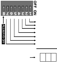
IOM ADDRESS SET UP
Each IOM should have its own
address. The address could range
from 1 to 127. Never use zero as
IOM address as zero is reserved
for the master device.
Note: It is recommended not to
attach more than 4 IOM units to the
RS485 bus to maintain a
reasonable signal/response time
delay between the reader and
IOMs. Hence IOM addresses must
be from 1 to 4 only.
To work out the address, select a
combination of bit locations on the
DIP switch. Each bit has its own
value representation. The RS485
address is obtained by adding all
ON-bit values. E.g. Decimal value
37 will be obtained by turning ON
bits 1, 3 and 6 which equivalents to
1+4+32.
NOTE: Please refer to IdentIPoint
Hardware Installation Manual (doc.
no. 95-7767) for more details on
the following items:
Overall system architecture
Power supply installation
Detailed wiring descriptions
for readers, IOM and
peripheral devices
Power-over-Ethernet wiring
RS485 ID
+ 1
+ 2
+ 4
+ 8
+ 16
+ 32
+ 64
RS485 ID
+ 1
+ 2
+ 4
+ 8
+ 16
+ 32
+ 64
SUMallONbitvalues
Neveruseaddresszero
SUMallONbitvalues
Neveruseaddresszero
RS485 ID
+ 1
+ 2
+ 4
+ 8
+ 16
+ 32
+ 64
RS485 ID
+ 1
+ 2
+ 4
+ 8
+ 16
+ 32
+ 64
SUMallONbitvalues
Neveruseaddresszero
SUMallONbitvalues
Neveruseaddresszero
Fig.28. IOM Address set up
95-7771
29

Honeywell IdentIPoint Intelligent Smartcard Readers
CERTIFICATIONS
Readers
CE
C-tick
IP-65 (Basic Outdoor
Version Only)
United States
FCC 47 CFR Part 15,
Subpart B, sections 107(a) &
109(a) Class B
Section 201 to Section 205,
section 207, section 209,
section 215c, section 247
and section 35c
European Union
EN 55022:2006; EN61000-
3-2:2006
EN 61000-6-3:2007
EN 50130-
4:1995+A1:1998+A2:2003
EN 50133-1:1997
EN 50133-2-1:2000
EN 50134-1:2000
EN 50134-3:2001
EN 60950-1:2001
EN 301 489-01 V1.6.1
EN 301 489-03 V1.4.1
EN 300 330-02 V1.3.1
IOM
CE
C-tick
United States
FCC 47 CFR Part 15,
Subpart B, sections 107(a) &
109(a) Class B
Section 201 to Section 202,
section 207
European Union
EN 55022:2006EN 60950-
1:2001
(CERTIFICATIONS ARE IN
PROGRESS)
WARNING: Any Changes
or modifications not
expressly approved by the party
responsible for compliance could
void the user’s authority to operate
the equipment.
This device complies with part 15
of the FCC Rules. Operation is
subject to the following two
conditions:
This device may not cause
harmful interference.
This device must accept any
interference received, including
interference that may cause
undesired operation.
95-7771
30
Honeywell IdentIPoint Intelligent Smartcard Readers
Notice
This document contains Honeywell
proprietary information. Information
contained herein is to be used
solely for the purpose submitted,
and no part of this document or its
contents shall be reproduced,
published, or disclosed to a third
party without the express
permission of Honeywell
International, Sarl.
While this information is presented
in good faith and believed to be
accurate, Honeywell disclaims the
implied warranties of
merchantability and fitness for a
purpose and makes no express
warranties except as may be stated
in its written agreement with and for
its customer.
In no event is Honeywell liable to
anyone for any direct, special, or
consequential damages.
The information and specifications
in this document are subject to
change without notice.
Copyright 2009 – Honeywell
International, Sarl.
Honeywell Trademarks
Honeywell Enterprise Buildings
IntegratorTM (EBI) and IdentIPointTM
are U.S. registered trademarks of
Honeywell, Inc.
Other Trademarks
Trademarks that appear in this
document are used only to the
benefit of the trademark owner,
with no intention of trademark
infringement.
Support and other contacts
For technical assistance, call your
nearest Honeywell office.
Feedback
Honeywell appreciates your
comments about this manual.
Please visit us on the web at
https://buildingsolutions.honeywell.
com to post your comments.
95-7771
31

Honeywell IdentIPoint Intelligent Smartcard Readers
www.honeywell.com/buildingsolutions
© 2009 Honeywell International Inc.
95-7771 10-09
Honeywell Building Solutions
North America:
1985 Douglas Drive North
Golden Valley, MN 55422-3992
+1-800-345-6770, ext. 606
Europe, Middle East, Africa & India:
Honeywell House
Arlington Business Park
Bracknell, United Kingdom RG12
1EB
+44 (0)870 600 1659
North Asia:
Zhang Jiang Hi-Tech Park
No. 430 Li Bing Rd., Pudong New
Area,
Shanghai, 201203, China
+86-21-2894-2000
South Asia Pacific:
2 Richardson Place
Sydney NSW 2113
+612-9353-7000