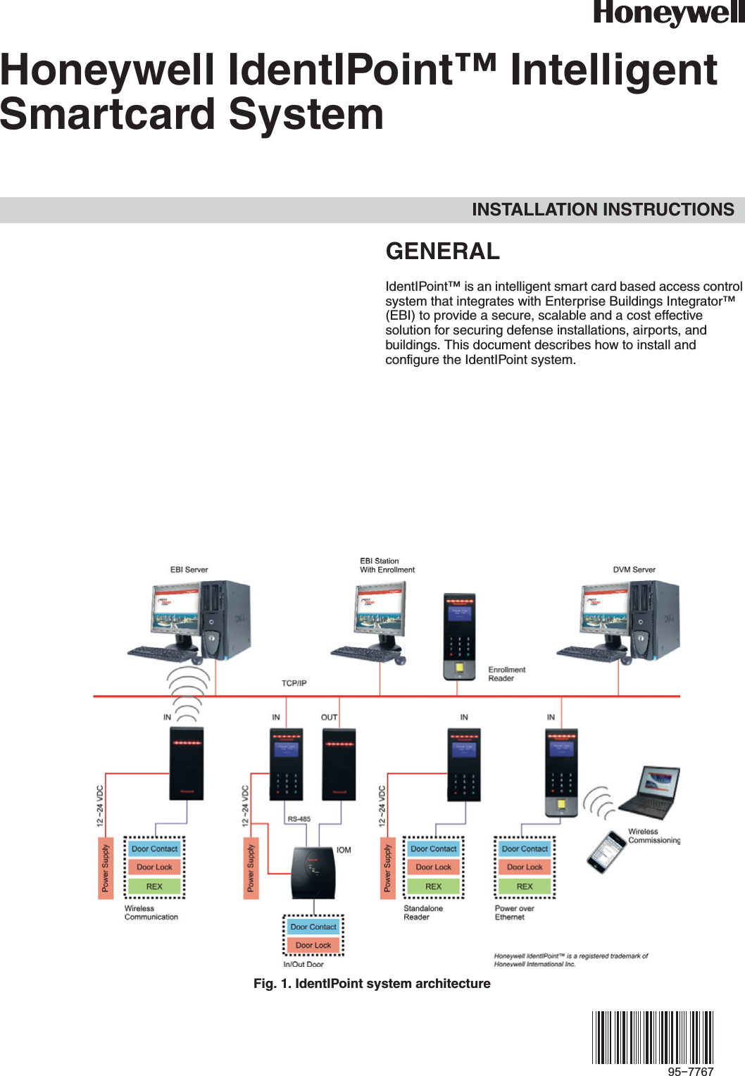
Honeywell BOTAC02 IdentIPoint User Manual
Honeywell Inc IdentIPoint
UserManual.wiki
>
Honeywell
>
BOTAC02 User Manual
Users Manual
Navigation menu
Upload a User Manual
Namespaces
Wiki Guide
HTML
PDF
Info
Views
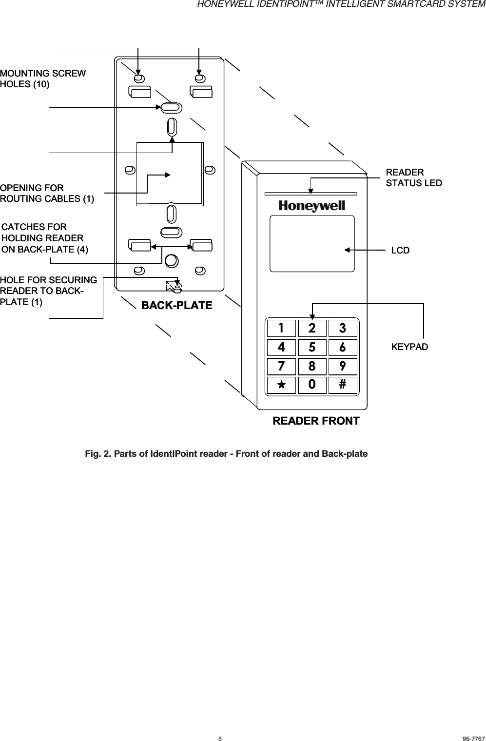
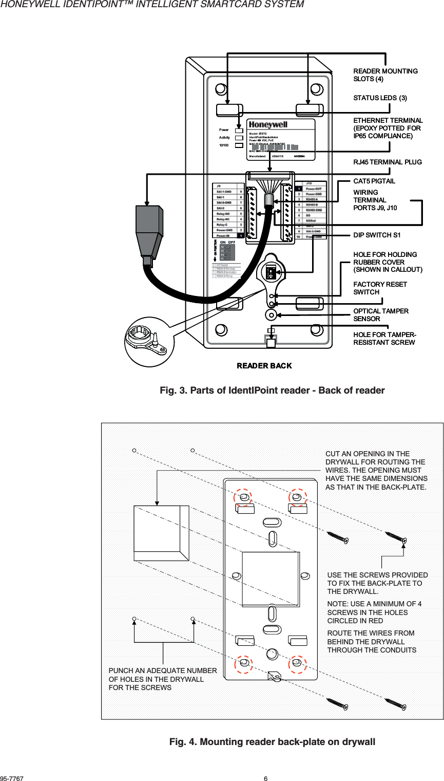
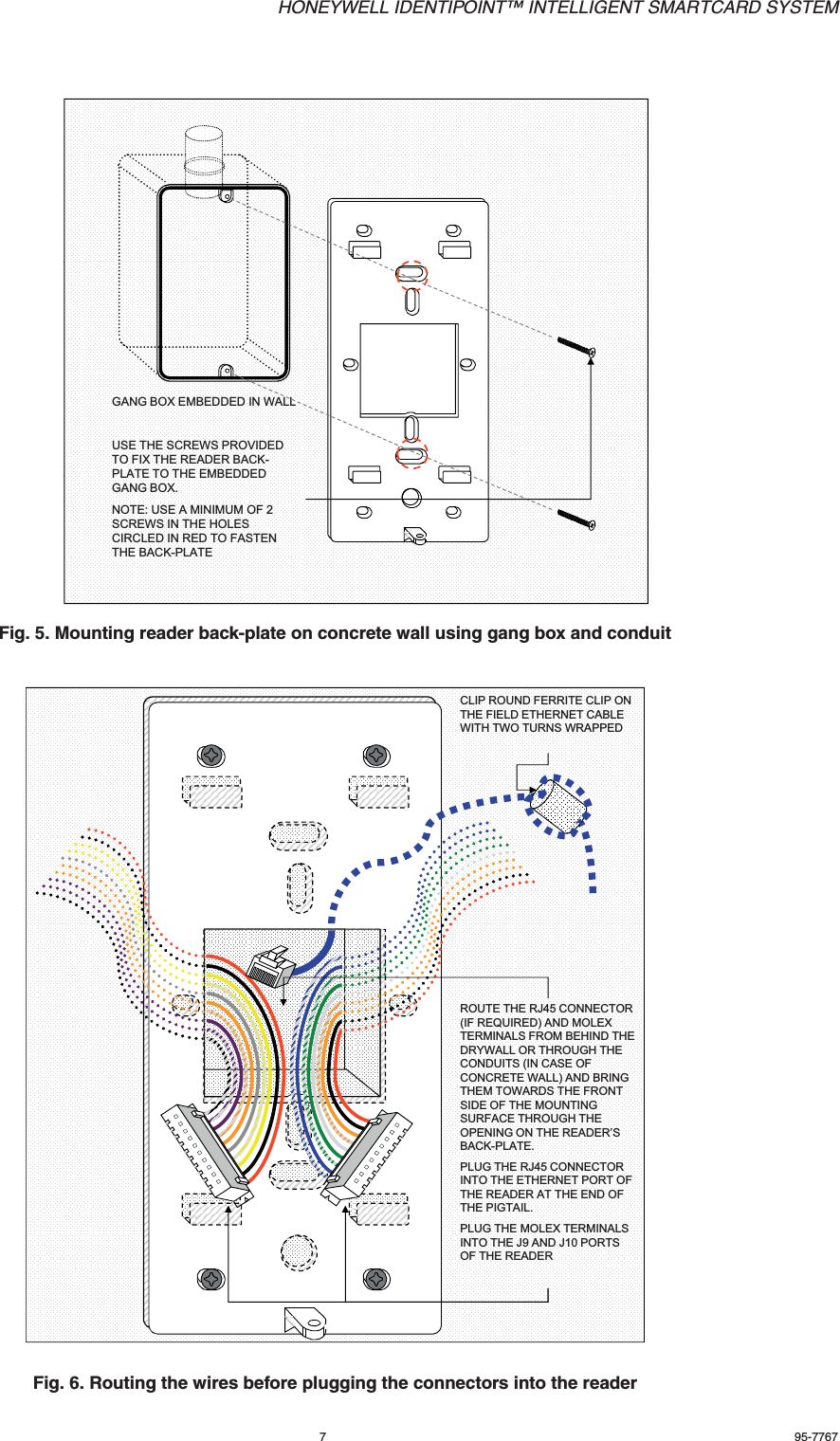
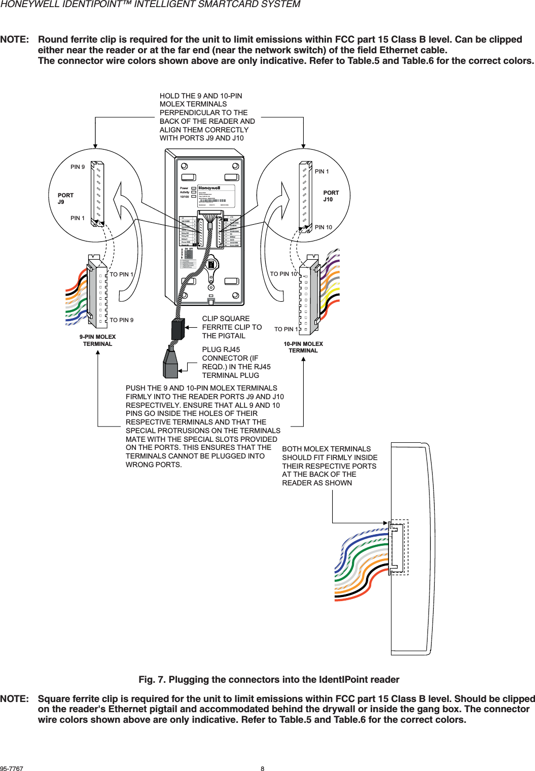
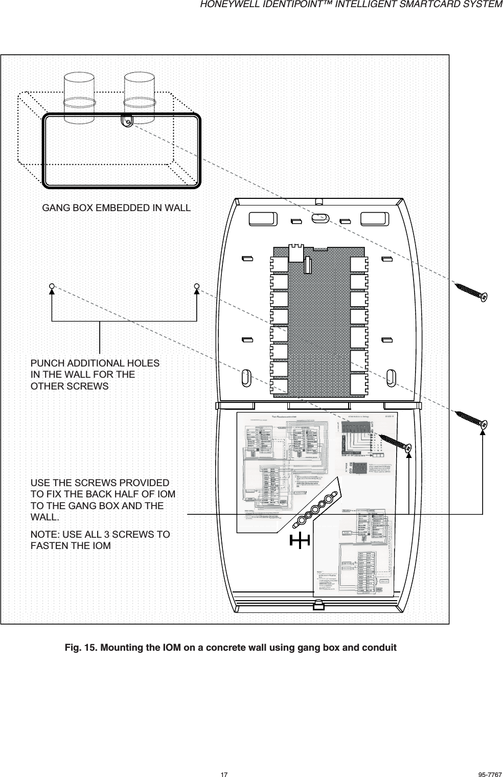
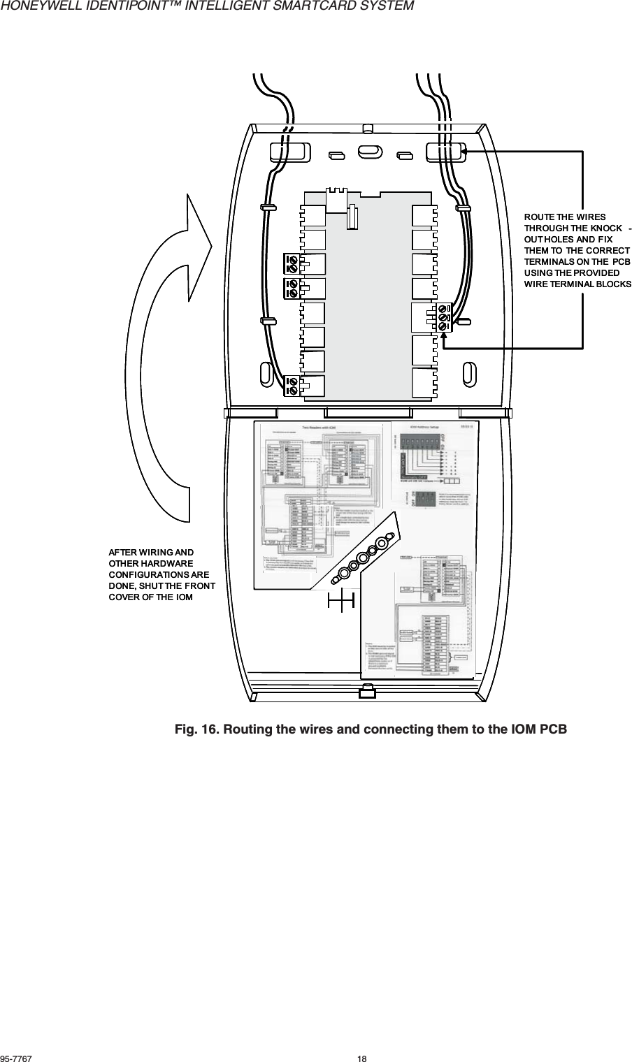
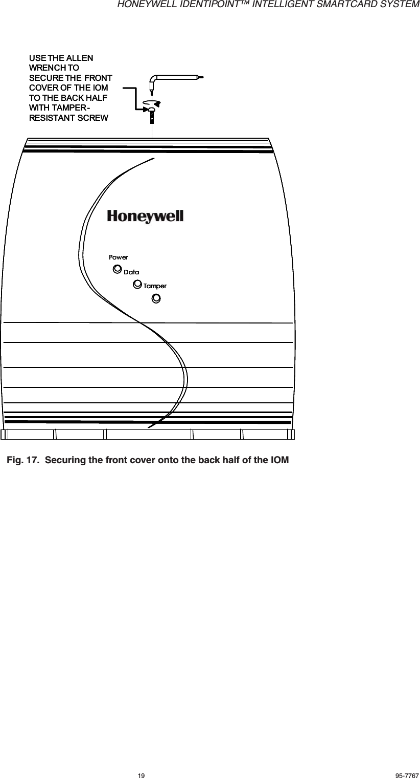
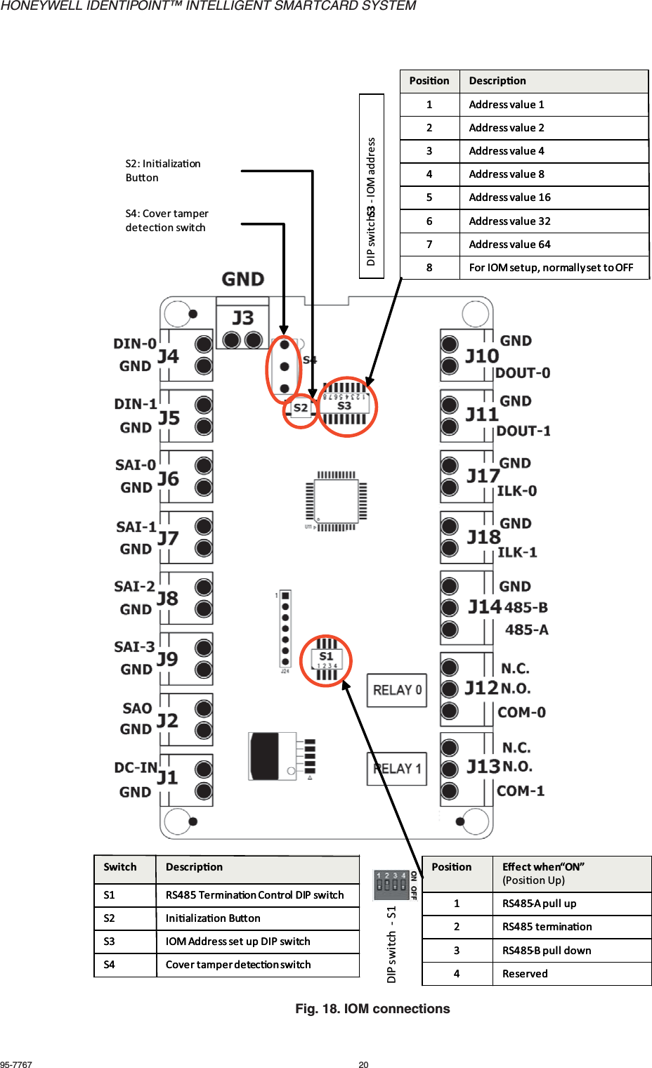
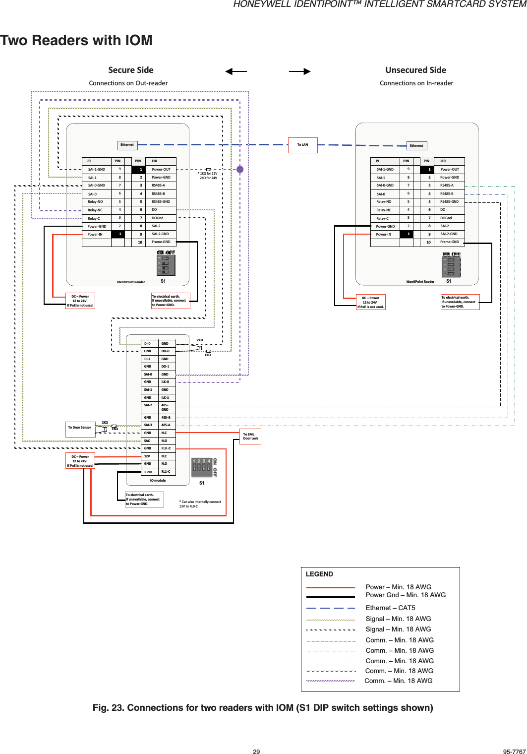
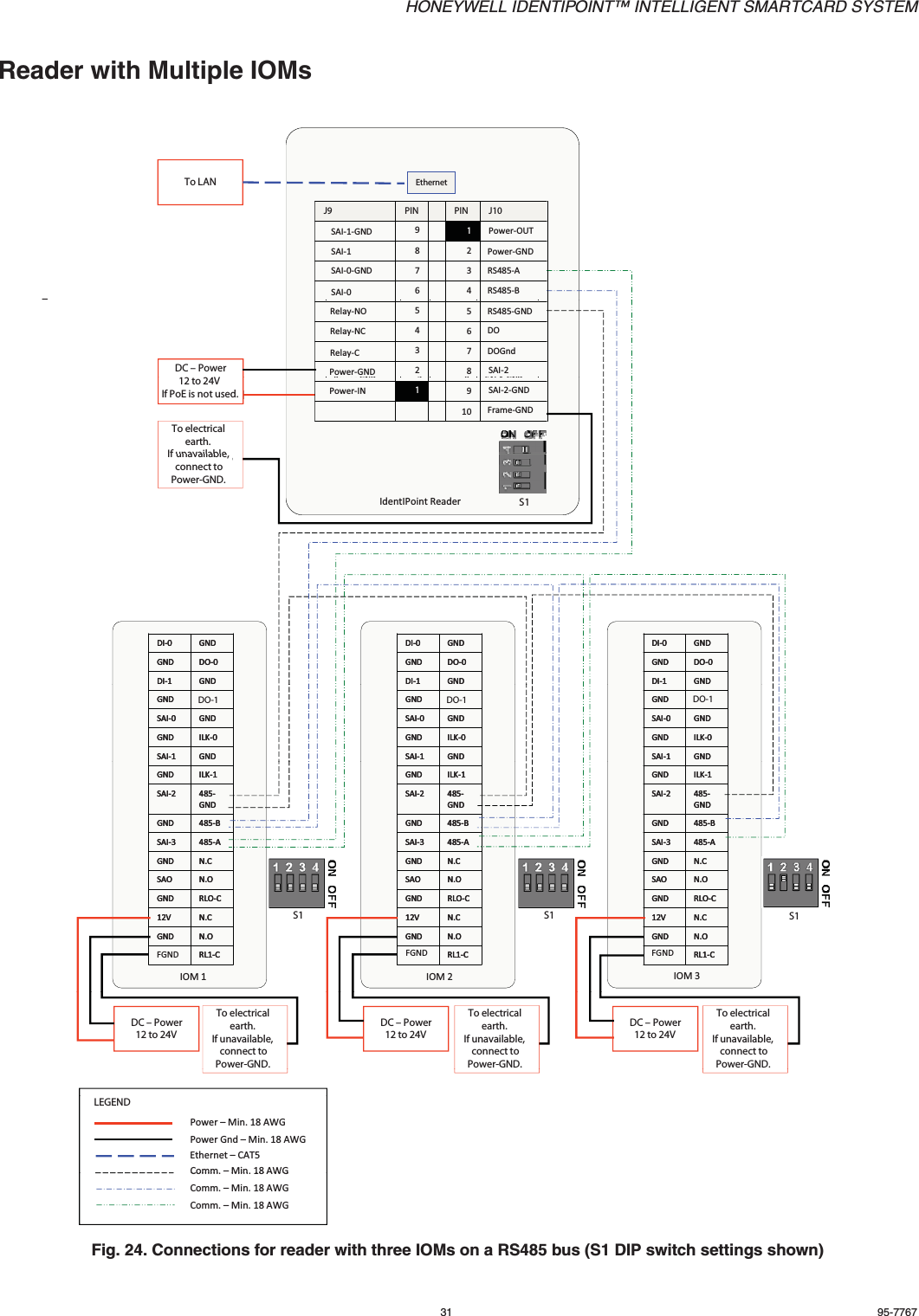
User Manual
Discussion / Help
Navigation