Honeywell BOTAC02 IdentIPoint User Manual
Honeywell Inc IdentIPoint
Users Manual
INSTALLATION INSTRUCTIONS
Put Bar Code Here
95−7767
Honeywell IdentIPoint™ Intelligent
Smartcard System
GENERAL
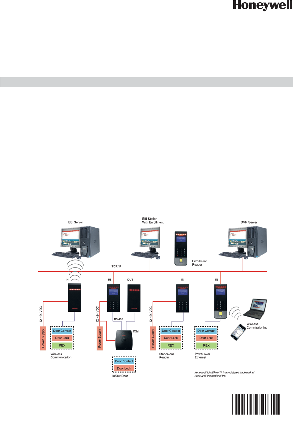
IdentIPoint™ is an intelligent smart card based access control
system that integrates with Enterprise Buildings Integrator™
(EBI) to provide a secure, scalable and a cost effective
solution for securing defense installations, airports, and
buildings. This document describes how to install and
configure the IdentIPoint system.
Fig. 1. IdentIPoint system architecture
HONEYWELL IDENTIPOINT™ INTELLIGENT SMARTCARD SYSTEM
95-7767 2
NOTE: For detailed connection diagrams see topics
Detailed Wiring Diagrams and Wiring Other
Devices.
NOTE: Any currently available IdentIPoint reader can be
used as an enrollment reader.
OVERVIEW
IdentIPoint is Honeywell's next generation smart card based
access control system in conjunction with Honeywell's award
winning Enterprise Buildings Integrator - EBITM. IdentIPoint
readers come with a powerful built-in controller thus
eliminating the need to install a separate multi-door access
controller. IdentIPoint offers flexible architecture options
including the option of connected and standalone readers.
The readers communicate with EBI over a wired or wireless*
Ethernet network.
The IdentIPoint hardware family consists of the following
models:
• Indoor / Outdoor basic readers - IP65 (BTBAS)
• Indoor readers with LCD & Keypad (BTSTD)
• Indoor readers with LCD, Keypad and Fingerprint
(BTFPT)2
• Remote Input Output Module (IOM) (BTIO)
IdentIPoint readers support the following Contactless Smart
Card Reader technologies:
• MIFARE Classic 1K, 4K
• MIFARE DESFire 4K
• MIFARE DESFire EV1 4K, 8K
IdentIPoint readers also support the following network
technologies:
• Wireless LAN IEEE802.11b/g standard; provides WPA
security for infrastructure mode of operation*.
• High speed 10/100 Mbps Ethernet connection for Wired
LAN via RJ45.
IdentIPoint readers support the following types of peripheral
connections:
• One RS485 serial bus (115200 baud) for IOM
• Bus Termination and BIAS for RS485 on board (jumpers or
dip switch)
• Digital Output 1 (current sinking at 1A, 24VDC max.)
• Supervised Inputs 3; capable of distinguishing 4 states
• Relay Contact 1 (1A-24VDC) - Form C
• Two Tamper Inputs:
— Inner Tamper Switch: Micro-switch (detecting casing
opening)
— Outer Tamper Switch: Optical (detecting unit dis-
mounted from wall)
The readers work with 12V to 24VDC power supply or Power-
over-Ethernet (PoE)* conforming to the IEEE 802.3af
standard. All software and firmware is remotely upgradeable
over the network via EBI.
All the IdentIPoint readers are designed to work with an
optional remote IOM. The IOM is used when the control inputs
and outputs of the door are desired to be on the secure side of
the door - for high security installations. The IOM integrates
seamlessly with the readers via a secure encrypted RS485
bus. Up to four IOMs can be connected via the same bus to a
reader. The IOMs are independently addressable via DIP
switches.
The IOM supports the following types of Inputs and Outputs:
• Relay: 2 - (1A 24VDC) Form C
• Digital Input: 2
• Digital Output: 2 (current sinking; (max 24V 1A)
• Supervised Analog Inputs : 4 ; capable of distinguishing 4
states
• Supervised Analog Output 1 - repeats the last Supervisory
Input, SAI3
The IOM works with a 12V to 24VDC power supply. It is
possible to control one door using two Readers in IN & OUT
mode with the help of an IOM.
* See Table.1.
Models and Part Numbers
The IdentIPoint product-line consists of the following three
reader models and one input/output unit:
1. Basic: Basic Indoor / Outdoor reader with IP65 rating3
(Part no.: BTBAS)
2. Standard: Indoor reader with LCD & Keypad (Part no.:
BTSTD)
3. Fingerprint: Indoor reader with LCD, Keypad and Fin-
gerprint unit (Part no.: BTFPT)2
4. IOM: Remote Input Output Module (Part no.: BTIO)
NOTE:
1. For device ratings, see product datasheet (Docu-
ment no. 74-5086).
2. The BTFPT module is not UL294 listed and shall
not be used for UL applications.
3. IP65 enclosure rating was not evaluated by UL.
BEFORE INSTALLATION
1. Verify the mounting locations with the job drawings.
2. Unpack the IdentIPoint reader, IOM and accessories
and check them. Report any damaged or missing com-
ponents to a Honeywell representative. A claim must be
filed with the commercial carrier responsible.

HONEYWELL IDENTIPOINT™ INTELLIGENT SMARTCARD SYSTEM
395-7767
WARNING
Fire Safety and Liability Notice: Never connect
card readers to any critical entry, exit door, barrier,
elevator or gate without providing an alternative
exit in accordance with all fire and life safety
codes pertinent to the installation. These fire and
safety codes vary from city to city and you must
get approval from local fire officials whenever
using an electronic product to control a door or
other barrier. Use of egress buttons, for example,
may be illegal in some cities.In most applications,
single action exit without prior knowledge of what
to do is a life safety requirement. Always make
certain that any required approvals are obtained in
writing. Verbal approvals are not valid.
IMPORTANT
Table 1.
IDENTIPOINT HARDWARE
Inside the reader box
• Intelligent Reader Unit - 1
• Mounting Plate - 1
• Mounting Hardware - Screws and Wall Anchors - 6 each
• Extra Tamper Resistant Screws - 2
• Tool for Tamper Resistant Screw - 1
• Connector with cable - 2 (9 and 10 pin)
• Resistors - 2K (Color Code: RED-BLACK-RED-GOLD;
0.5W axial type, 5% tolerance) - 3
• Resistors - 1K (Color Code: BROWN-BLACK-RED-GOLD;
0.5W axial type, 5% tolerance) - 3
• Square ferrite clip - 1
• Round ferrite clip - 1
• Quick Installation Guide - 1
Inside the IOM box
• Input / Output Module Unit - 1
• Mounting Hardware - Screws and Wall Anchors - 3 each
• Extra Tamper Resistant Screws - 2
• Tool for Tamper Resistant Screw - 1
• Connectors for termination - 12 x 2 connections; 3 x 3
connections
• Resistors - 2K (Color Code: RED-BLACK-RED-GOLD;
0.5W axial type, 5% tolerance) - 4
• Resistors - 1K (Color Code: BROWN-BLACK-RED-GOLD;
0.5W axial type, 5% tolerance) - 6
• Quick Installation Guide - 1
ASSEMBLY, MOUNTING AND
INSTALLATION
Mounting and Installing the Reader
NOTE:
• The reader can be mounted either on a drywall or on
a concrete wall using conduits and a gang box.
1 For UL294 applications, only UL294 and/or UL1076 listed power supplies should be used for reader and
lock power with required 72 hour battery backup.
2 Use of PoE is not a UL294 listed configuration and should not be used on UL294 applications.
3 Wifi network configuration is not a UL294 listed configuration and should not be used on UL294
applications.
4 As a standalone or disconnected reader is not supervised, this configuration should not be used on
UL294 applications.
5 For UL294 applications using an IOM, note that the IOM needs to be kept on the secure side of the door
i.e. indoors, and within a distance of 7.5 meters from the reader to which it is connected. In case the
distance between the IOM and the reader exceeds 7.5 meters, the use of lightning protection devices on
the RS485 line is mandatory.
6 The class of these products is a UL294 Access Control System, complying with UL294 Attack
Class I.

HONEYWELL IDENTIPOINT™ INTELLIGENT SMARTCARD SYSTEM
95-7767 4
• The drywall and gang boxes shown here are just
representations of the actual hardware. During
installation, please use the hardware as per the
required dimensions and availability.
• To install IdentIPoint devices in place of older devices
that have been removed, you may use the
TRADELINE® 209651A Universal Cover Plate to
cover marks from the older devices and allow
mounting of IdentIPoint devices on vertical or
horizontal outlet boxes. See document no. 69-1093
for more details.
WARNING
Earth ground all enclosures for proper installation.
It is mandatory to connect the "Frame Ground" on
the J10 terminal of the fingerprint reader to an
electronic earth. In case an electronic earth is not
available then "Frame Ground" can be connected
to the Input Power Supply earth or common
ground available nearby.
WARNING
Make all electrical field connections to reader and
IOM(s) before applying DC power to configuration.
Failure to do so and connecting positive terminal
first on IOM before negative can result in failed
operation that would require power recycling. Do
not make power connections with power applied
to wiring/terminal blocks - power down all circuits
before connecting or disconnecting all terminal
blocks on reader or IOM.
Drywall Mounting
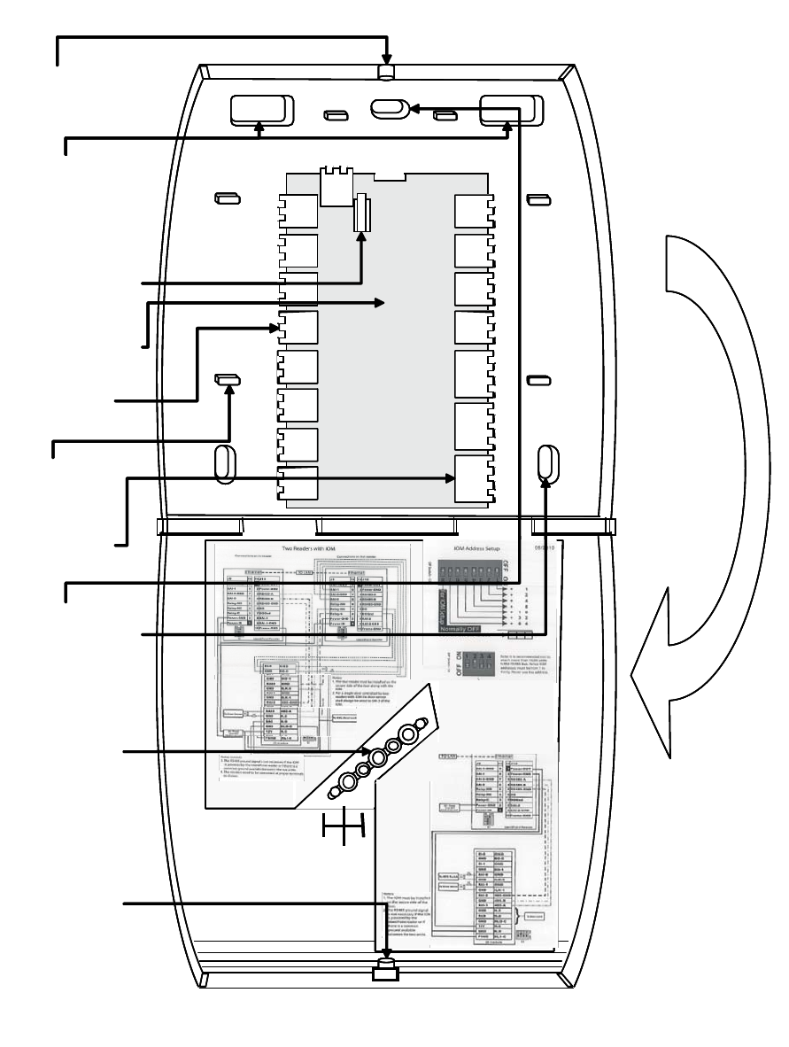
1. Fig.2 and Fig.3 show the parts of the IdentIPoint reader.
Use the back-plate of the reader to mark out the posi-
tion of the reader on the drywall. Mark the positions of
the mounting screws and the opening for routing the
cables.
2. Cut the cable opening on the drywall using suitable
tools and punch an adequate number of holes for the
mounting screws. It is advisable to use at least four
screws to mount the reader. Use the wall anchors for
additional holding strength. See Fig.4.
3. Hold the back-plate in position on the drywall. Align the
mounting screws with their holes and fasten the back-
plate securely on the drywall using the screws. See
Fig.4.
4. Route the field wires including the Ethernet cable (if
required) from behind the drywall through the cable
opening and bring them to the front of the mounting sur-
face. See Fig.6. Clip the square* ferrite clip on the
reader's Ethernet pigtail. See Fig.7. Connect the field
wiring to the correct Molex pigtails. See Table.2 for wire
sizes and distances. For reader connection details see
Fig.11 and Table.5 and Table.6. Plug the Molex termi-
nal(s) in ports J9 and J10 at the back of the reader. See
Fig.7. Clip (with two turns wrapped) the round** ferrite
clip on the field Ethernet cable. See Fig.6. Plug the
RJ45 connector of the field Ethernet cable into the
Ethernet port of the reader at the end of the pigtail. See
Fig.7. Drop the excess lengths of Molex and Ethernet
wires behind the drywall. Set the S1 DIP switch if the
reader is to be connected to an IOM via RS485. See
Fig.11, Table.7 and Section RS485 Communication and
Termination Setting of Connector and Switch Descrip-
tions topic for more details.
5. Once all the connections and settings are done, hold
the reader against the back-plate, aligning the mounting
slots at the back of the reader with their corresponding
catches on the back-plate and push it downwards until it
hooks into place firmly. See Fig.8 and Fig.9.
6. Use the Allen wrench to tighten the tamper-resistant
screw at the bottom of the reader into the hole provided
on the back-plate so as to fasten the reader to the back-
plate securely. See Fig.10.
* Required for the unit to limit emissions within FCC part 15
Class B level. Should be clipped on the reader's Ethernet
pigtail and accommodated behind the drywall.
** Required for the unit to limit emissions within FCC part 15
Class B level. Can be clipped either near the reader or at the
far end (near the network switch) of the field Ethernet cable.
Gang Box (concrete wall) Mounting
1. Fig.2 and Fig.3 show the parts of the IdentIPoint reader.
Ensure that the correct sized gang box is securely
embedded in the concrete wall. The holes provided in
the gang box for the screws should align properly with at
least two of the holes provided in the reader back-plate
for the screws.
2. Hold the back-plate in position over the gang box. Align
the mounting screws with their holes and fasten the
back-plate securely on the gang box using the screws.
See Fig.5.
3. Route the field wiring including the Ethernet cable (if
required) from the conduits into the gang box. Clip the
square* ferrite clip on the reader's Ethernet pigtail. See
Fig.7. Connect the field wiring to the correct Molex pig-
tails. See Table.2 for wire sizes and distances. For
reader connection details see Fig.11 and Table.5 and
Table.6. Route the Molex terminal(s) through the cable
opening on the back-plate towards the front of the
mounting surface (see Fig.6) and plug them in ports J9
and J10 at the back of the reader. See Fig.7. Clip (with
two turns wrapped) the round** ferrite clip on the field
Ethernet cable. See Fig.6. Plug the RJ45 connector of
the field Ethernet cable into the Ethernet port of the
reader provided at the end of the pigtail. See Fig.7.
Allow room for the Molex and Ethernet pigtails inside the
gang box. Set the S1 DIP switch if the reader is to be
connected to an IOM via RS485. See Fig.11, Table.7
and Section RS485 Communication and Termination
Setting of Connector and Switch Descriptions topic for
more details.
4. Once all the connections and settings are done, hold
the reader against the back-plate, aligning the mounting
slots at the back of the reader with their corresponding
catches on the back-plate and push it downwards until it
hooks into place firmly. See Fig.8 and Fig.9.
5. Use the Allen wrench to tighten the tamper-resistant
screw at the bottom of the reader into the hole provided
on the back-plate so as to fasten the reader to the back-
plate securely. See Fig.10.
* Required for the unit to limit emissions within FCC part 15
Class B level. Should be clipped on the reader's Ethernet
pigtail and accommodated inside the gang box.
** Required for the unit to limit emissions within FCC part 15
Class B level. Can be clipped either near the reader or at the
far end (near the network switch) of the field Ethernet cable.
HONEYWELL IDENTIPOINT™ INTELLIGENT SMARTCARD SYSTEM
595-7767
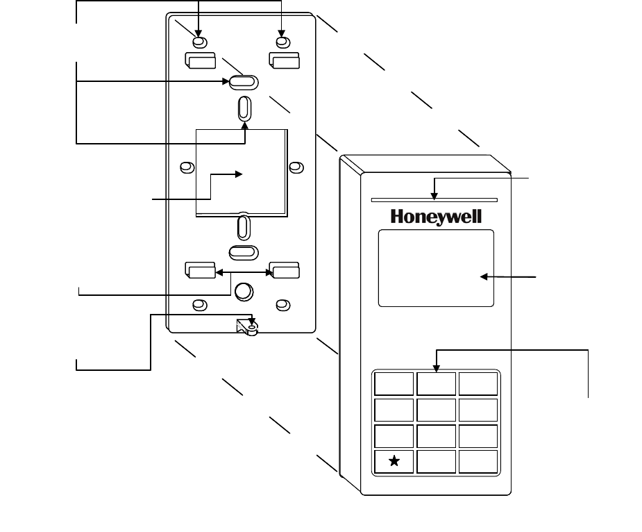
Fig. 2. Parts of IdentIPoint reader - Front of reader and Back-plate
BACK-PLATE
CATCHES FOR
HOLDING READER
ON BACK-PLATE (4)
READER
STATUS LED
KEYPAD
READER FRONT
MOUNTING SCREW
HOLES (10)
OPENING FOR
ROUTING CABLES (1)
123
456
789
0#
LCD
HOLE FOR SECURING
READER TO BACK-
PLATE (1) BACK-PLATE
CATCHES FOR
HOLDING READER
ON BACK-PLATE (4)
READER
STATUS LED
KEYPAD
READER FRONT
MOUNTING SCREW
HOLES (10)
OPENING FOR
ROUTING CABLES (1)
123
456
789
0#
LCD
HOLE FOR SECURING
READER TO BACK-
PLATE (1)
HONEYWELL IDENTIPOINT™ INTELLIGENT SMARTCARD SYSTEM
95-7767 6
Fig. 3. Parts of IdentIPoint reader - Back of reader
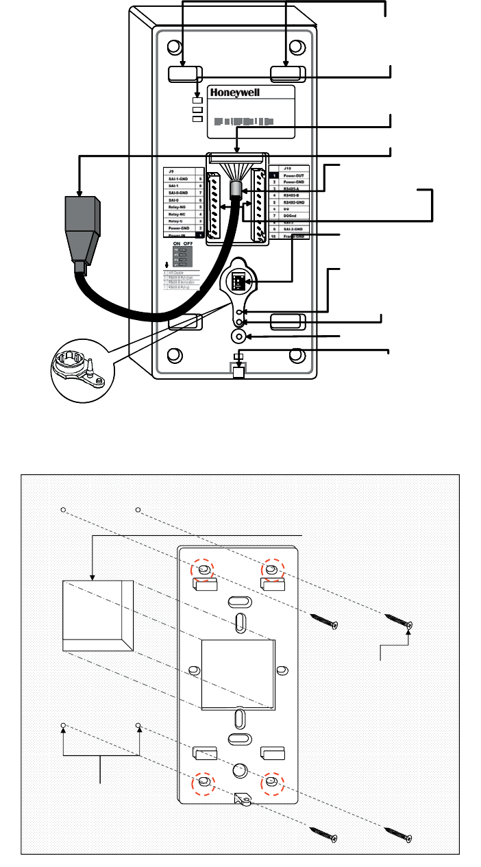
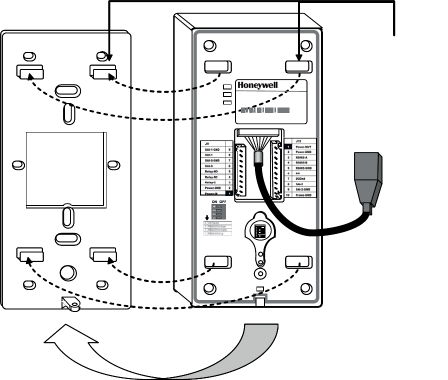
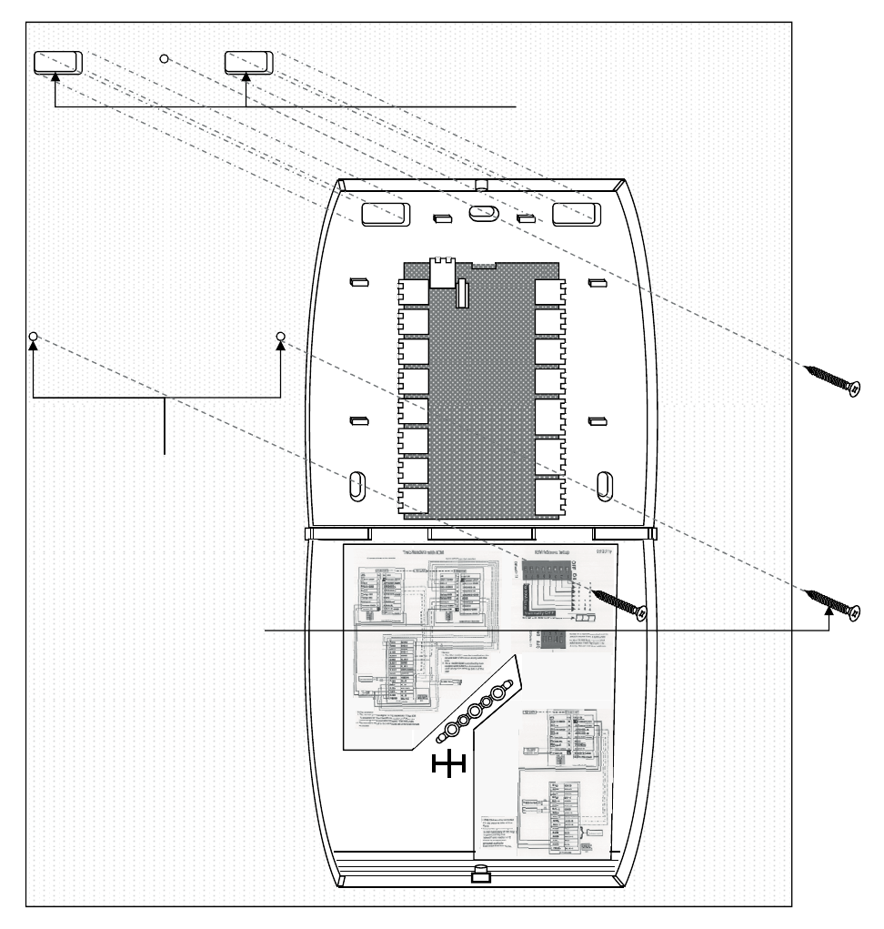
Fig. 4. Mounting reader back-plate on drywall
READER MOUNTING
SLOTS (4)
STATUS LEDS (3)
DIP SW ITCH S1
READER BACK
10/100
Activity
Power
ETHERNET TERMINAL
(EPOXY POTTED FOR
IP65 COMPLIANCE)
FACTORY RESET
SWITCH
OPTICAL TAMPER
SENSOR
WIRING
TERMINAL
PORTS J9, J10
HOLE FOR TAMPER-
RESISTANT SCREW
CAT5 PIGTAIL
HOLE FOR HOLDING
RUBBER COVER
(SHOWN IN CALLOUT)
RJ45 TERMINAL PLUG
Model: BTSTD
IdentIPoin t Stan da rd Indoor
Power 1 0-28 VDC, PoE
M AC ID Eth ern et 00 40 84 0A F 33 E
MAC ID Wi-fi 00408-IOAF33F
Manu factured: 2 00 9. 0 7. 13 MAD E IN CHINA
1
2
3
4
1
2
3
4
ON P OS I T IONON P OS I T ION
READER MOUNTING
SLOTS (4)
STATUS LEDS (3)
DIP SW ITCH S1
READER BACK
10/100
Activity
Power
ETHERNET TERMINAL
(EPOXY POTTED FOR
IP65 COMPLIANCE)
FACTORY RESET
SWITCH
OPTICAL TAMPER
SENSOR
WIRING
TERMINAL
PORTS J9, J10
HOLE FOR TAMPER-
RESISTANT SCREW
CAT5 PIGTAIL
HOLE FOR HOLDING
RUBBER COVER
(SHOWN IN CALLOUT)
RJ45 TERMINAL PLUG
Model: BTSTD
IdentIPoin t Stan da rd Indoor
Power 1 0-28 VDC, PoE
M AC ID Eth ern et 00 40 84 0A F 33 E
MAC ID Wi-fi 00408-IOAF33F
Manu factured: 2 00 9. 0 7. 13 MAD E IN CHINA
1
2
3
4
1
2
3
41
2
3
4
1
2
3
4
1
2
3
4
ON P OS I T IONON P OS I T IONON P OS I T IONON P OS I T ION
CUT AN OPENING IN THE
DRYWALL FOR ROUTING THE
WIRES THE OPENING MUST
WIRES
.
THE OPENING MUST
HAVE THE SAME DIMENSIONS
AS THAT IN THE BACK-PLATE.
USE THE SCREWS PROVIDED
TO FIX THE BACK-PLATE TO
THE DRYWALL.
THE DRYWALL.
NOTE: USE A MINIMUM OF 4
SCREWS IN THE HOLES
CIRCLED IN RED
ROUTE THE WIRES FROM
BEHIND THE DRYWALL
THROUGH THE CONDUITS
PUNCH AN ADEQUATE NUMBER
OF HOLES IN THE DRYWALL
FOR THE SCREWS
HONEYWELL IDENTIPOINT™ INTELLIGENT SMARTCARD SYSTEM
795-7767
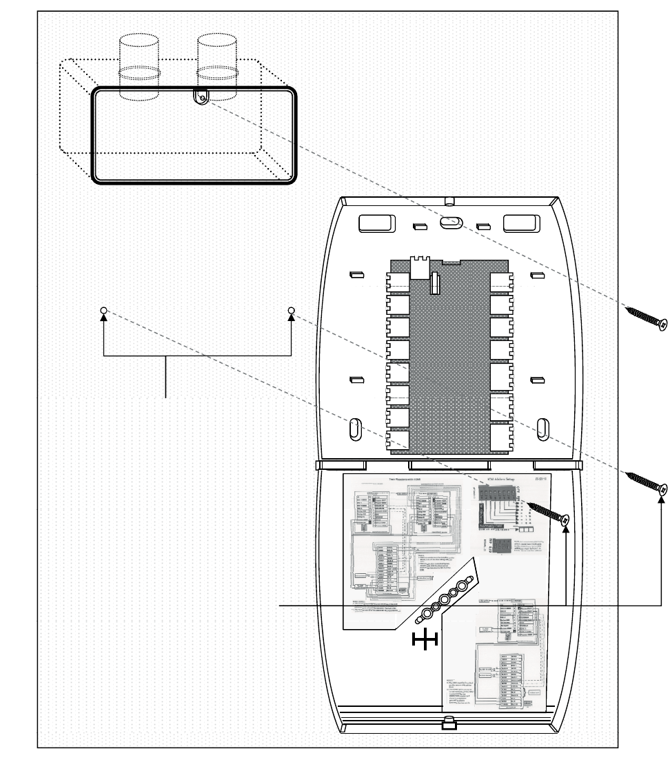
Fig. 5. Mounting reader back-plate on concrete wall using gang box and conduit
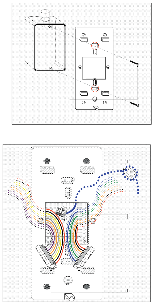
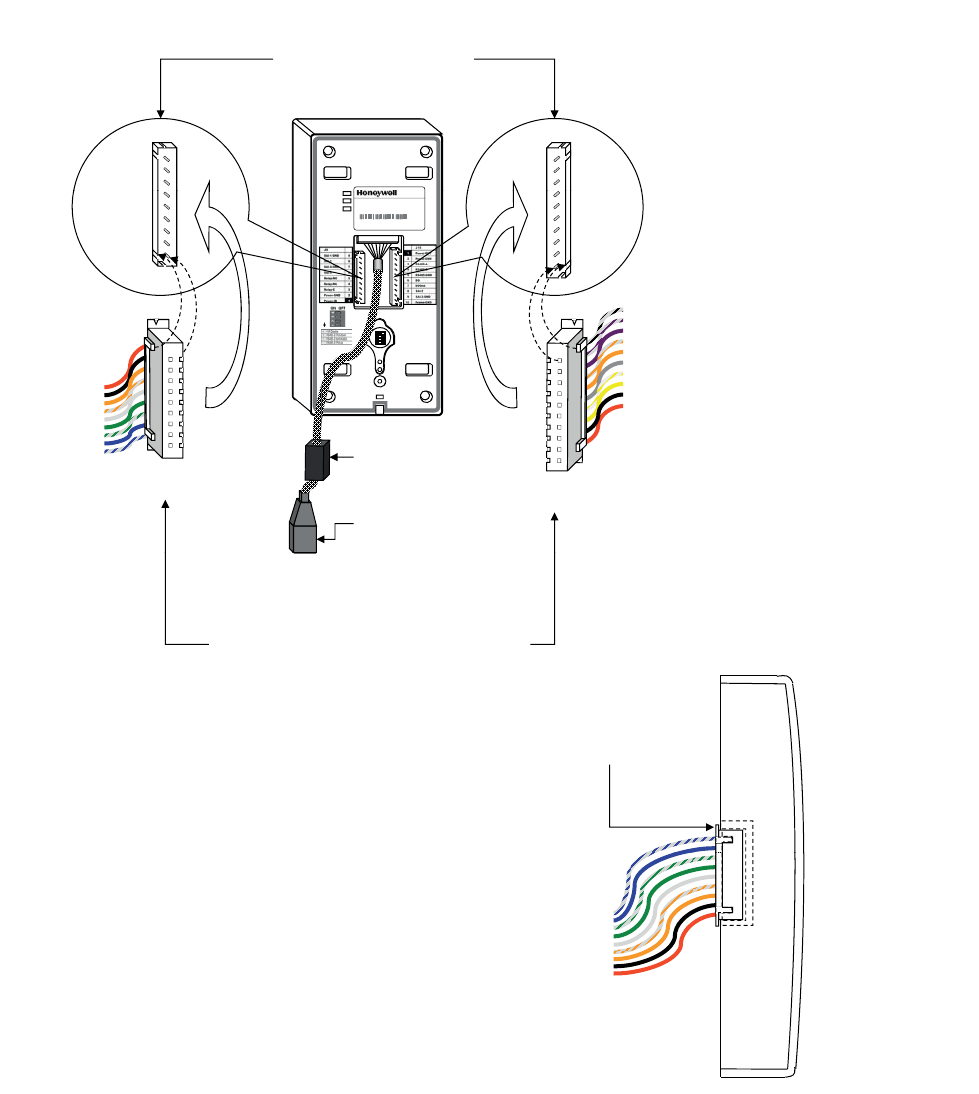
Fig. 6. Routing the wires before plugging the connectors into the reader
USE THE SCREWS PROVIDED
TO FIX THE READER BACK-
PLATE TO THE EMBEDDED
GANG BOX EMBEDDED IN WALL
PLATE TO THE EMBEDDED
GANG BOX.
NOTE: USE A MINIMUM OF 2
SCREWS IN THE HOLES
CIRCLED IN RED TO FASTEN
THE BACK-PLATE
CLIP ROUND FERRITE CLIP ON
THE FIELD ETHERNET CABLE
THE FIELD ETHERNET CABLE
WITH TWO TURNS WRAPPED
ROUTE THE RJ45 CONNECTOR
(IF REQUIRED) AND MOLEX
(IF REQUIRED) AND MOLEX
TERMINALS FROM BEHIND THE
DRYWALL OR THROUGH THE
CONDUITS (IN CASE OF
CONCRETE WALL) AND BRING
THEM TOWARDS THE FRONT
SIDE OF THE MOUNTING
SURFACE THROUGH THE
OPENING ON THE READER’S
OPENING ON THE READER’S
BACK-PLATE.
PLUG THE RJ45 CONNECTOR
INTO THE ETHERNET PORT OF
THE READER AT THE END OF
THE PIGTAIL.
PLUG THE MOLEX TERMINALS
PLUG THE MOLEX TERMINALS
INTO THE J9 AND J10 PORTS
OF THE READER
HONEYWELL IDENTIPOINT™ INTELLIGENT SMARTCARD SYSTEM
95-7767 8
NOTE: Round ferrite clip is required for the unit to limit emissions within FCC part 15 Class B level. Can be clipped
either near the reader or at the far end (near the network switch) of the field Ethernet cable.
The connector wire colors shown above are only indicative. Refer to Table.5 and Table.6 for the correct colors.
Fig. 7. Plugging the connectors into the IdentIPoint reader
NOTE: Square ferrite clip is required for the unit to limit emissions within FCC part 15 Class B level. Should be clipped
on the reader's Ethernet pigtail and accommodated behind the drywall or inside the gang box. The connector
wire colors shown above are only indicative. Refer to Table.5 and Table.6 for the correct colors.
BOTH MOLEX TERMINALS
SHOULD FIT FIRMLY INSIDE
THEIR RESPECTIVE PORTS
AT THE BACK OF THE
AT THE BACK OF THE
READER AS SHOWN
HOLD THE 9 AND 10-PIN
MOLEX TERMINALS
PERPENDICULAR TO THE
BACK OF THE READER AND
BACK OF THE READER AND
ALIGN THEM CORRECTLY
WITH PORTS J9 AND J10
PIN 9 PIN 1
PIN 1
PORT
J9
PIN 10
PORT
J10
10/100
A
ctivity
Power
Model: BTSTD
IdentIPoi nt Standar d Indoor
Power 10-28 VDC, PoE
MAC ID Ethernet 0040840AF33E
MAC ID Wi-fi 00408-IOAF33F
Manufactured: 2009.07.13 MADE IN CHINA
O
N
O
N
O
N
O
N
TO PIN 1 TO PIN 10
ON POSITI
O
ON POSITI
O
ON POSITI
O
ON POSITI
O
1
2
3
4
1
2
3
41
2
3
4
1
2
3
4
1
2
3
4
PLUG RJ45
CONNECTOR (IF
REQD.) IN THE RJ45
TERMINAL PL
UG
TO PIN 9
9-PIN MOLEX
TERMINAL 10-PIN MOLEX
TERMINAL
TO PIN 1
CLIP SQUARE
FERRITE CLIP TO
THE PIGTAIL
PUSH THE 9 AND 10-PIN MOLEX TERMINALS
FIRMLY INTO THE READER PORTS J9 AND J10
RESPECTIVELY. ENSURE THAT ALL 9 AND 10
PINS GO INSIDE THE HOLES OF THEIR
RESPECTIVE TERMINALS AND THAT THE
SPECIAL PROTRUSIONS ON THE TERMINALS
MATE WITH THE SPECIAL SLOTS PROVIDED
UG
MATE WITH THE SPECIAL SLOTS PROVIDED
ON THE PORTS. THIS ENSURES THAT THE
TERMINALS CANNOT BE PLUGGED INTO
WRONG PORTS.
HONEYWELL IDENTIPOINT™ INTELLIGENT SMARTCARD SYSTEM
995-7767
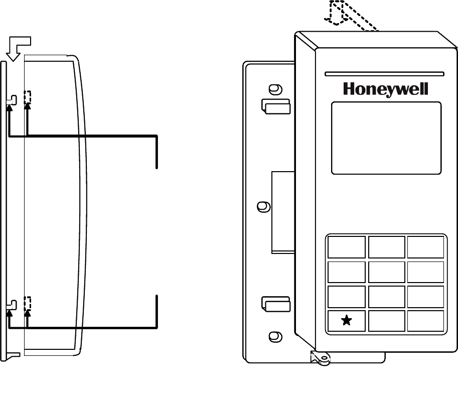
Fig. 8. Aligning IdentIPoint reader with back-plate before mounting it
ALIGN THE MOUNTING
SLOTS BEHIND THE
READER WITH THEIR
CORRESPONDING
CATCHES ON THE
BACK-PLATE
10/100
Activity
Power
Model: BTSTD
IdentIPoint Stan da rd Indoor
Power 1 0-28 VDC, PoE
M AC ID Eth ernet 00 40 84 0A F 33 E
MAC ID Wi-fi 00408-I OA F 3 3 F
Manufactured: 2009.07.13 MA D E IN CHINA
ON P OS I T I ONON P OS I T I ONON P OS I T I ONON P OS I T I ON
1
2
3
4
1
2
3
41
2
3
4
1
2
3
4
1
2
3
4
HONEYWELL IDENTIPOINT™ INTELLIGENT SMARTCARD SYSTEM
95-7767 10
Fig. 9. Mounting IdentIPoint reader on the back-plate
READER ASSEMBLY –
SIDE VIEW
ALIGN THE MOUNTING
SLOTS BEHIND THE
READER WITH THEIR
CORRESPONDING
CATCHES ON THE
BACK-PLATE. PUSH
THE READER
DOWNWARDS UNTIL IT
HOOKS INTO PLACE
FIRMLY
READER ASSEMBLY –
FRONT VIEW
123
456
789
0#
READER ASSEMBLY –
SIDE VIEW
ALIGN THE MOUNTING
SLOTS BEHIND THE
READER WITH THEIR
CORRESPONDING
CATCHES ON THE
BACK-PLATE. PUSH
THE READER
DOWNWARDS UNTIL IT
HOOKS INTO PLACE
FIRMLY
READER ASSEMBLY –
FRONT VIEW
123
456
789
0#
HONEYWELL IDENTIPOINT™ INTELLIGENT SMARTCARD SYSTEM
11 95-7767
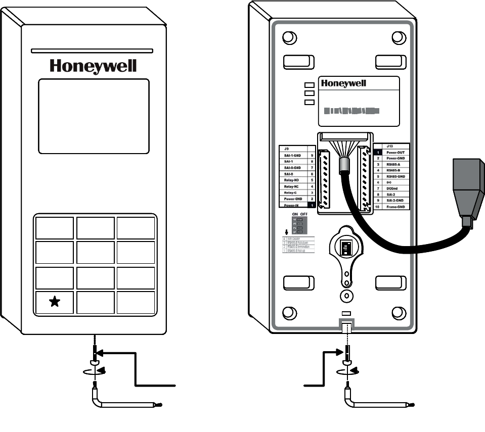
Fig. 10. Securing the IdentIPoint reader to the back-plate
10/100
Activity
Power
Model: BTSTD
IdentIPoint St an dard Indoor
Power 1 0-2 8 VDC, PoE
M AC ID Eth ernet 00 40 84 0A F 33 E
MAC ID Wi-fi 00408-IOAF33F
Manufactured: 2009.07.13 MA DE IN CHINA
ON POSITIONON POSITIONON POSITIONON POSITION
1
2
3
4
1
2
3
41
2
3
4
1
2
3
4
1
2
3
4
USE THE ALLEN
WRENCH TO
SECURE THE
READER TO THE
BACK-PLATE WITH
THE TAMPER-
RESISTANT SCREW
123
456
789
0#
HONEYWELL IDENTIPOINT™ INTELLIGENT SMARTCARD SYSTEM
95-7767 12
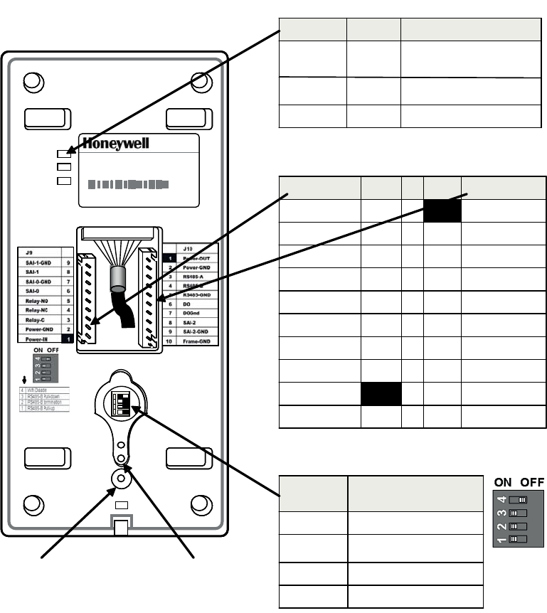
Fig. 11. Reader connections
Mounting and Installing the Input/Output
Module
NOTE:
• The IOM can be mounted either on a drywall or on a
concrete wall using conduits and a gang box.
• The drywall and gang boxes shown here are just
representations of the actual hardware. During
installation, please use the hardware as per the
required dimensions and availability.
• To install IdentIPoint devices in place of older devices
that have been removed, you may use the
TRADELINE® 209651A Universal Cover Plate to
cover marks from the older devices and allow
mounting of IdentIPoint devices on vertical or
horizontal outlet boxes. See document no. 69-1093
for more details.
10/100
Ac tiv i ty
Po w e r
Model: BTSTD
IdentIP oint S tandard Indoor
Power 10-28 VDC, PoE
MAC ID E thernet 0040840A F33E
MA C ID W i-fi 00408-IO A F33F
Manufactured: 2009.07.13 MA DE IN CHINA
ON P OSITIONON P OSITIONON P OSITIONON P OSITION
1
2
3
4
1
2
3
41
2
3
4
1
2
3
4
1
2
3
4
10/100
Ac tiv i ty
Po w e r
Model: BTSTD
IdentIP oint S tandard Indoor
Power 10-28 VDC, PoE
MAC ID E thernet 0040840A F33E
MA C ID W i-fi 00408-IO A F33F
Manufactured: 2009.07.13 MA DE IN CHINA
ON P OSITIONON P OSITIONON P OSITIONON P OSITION
1
2
3
4
1
2
3
41
2
3
4
1
2
3
4
1
2
3
4
Marking Color Descripon
10/100 Green On when network is 100
MBit
Acvity Orange Flashes on network acvity
Power Blue On if power on
Marking Color Descripon
10/100 Green On when network is 100
MBit
Acvity Orange Flashes on network acvity
Power Blue On if power on
J9 PIN PIN J10
SAI-1-GND 91Power-OUT
SAI-1 8 2 Power-GND
SAI-0-GND 7 3 RS485-A
SAI-0 6 4 RS485-B
Relay-NO 5 5 RS485-GND
Relay-NC 4 6 DO
Relay-C 3 7 DOGnd
Power-GND 2 8 SAI-2
Power-IN 19SAI-2-GND
10 Frame-GND
J9 PIN PIN J10
SAI-1-GND 91Power-OUT
SAI-1 8 2 Power-GND
SAI-0-GND 7 3 RS485-A
SAI-0 6 4 RS485-B
Relay-NO 5 5 RS485-GND
Relay-NC 4 6 DO
Relay-C 3 7 DOGnd
Power-GND 2 8 SAI-2
Power-IN 19SAI-2-GND
10 Frame-GND
Posion Effect when “ON”
(Posion Le)
1 RS485-A pull up
2 RS485 terminaon
3 RS485-B pull down
4WifiDisable
Posion Effect when “ON”
(Posion Le)
1 RS485-A pull up
2 RS485 terminaon
3 RS485-B pull down
4WifiDisable
DIP SWITCH S1
CONNECTORS AT THE BACK
LED INDICATORS AT THE BACK
FACTORY
RESET
SWITCH
OPTICAL
ALARM
TAMPER

HONEYWELL IDENTIPOINT™ INTELLIGENT SMARTCARD SYSTEM
13 95-7767
WARNING
Make all electrical field connections to reader and
IOM(s) before applying DC power to configuration.
Failure to do so and connecting positive terminal
first on IOM before negative can result in failed
operation that would require power recycling. Do
not make power connections with power applied
to wiring/terminal blocks - power down all circuits
before connecting or disconnecting all terminal
blocks on reader or IOM.
WARNING
Grounds need to be affixed first before applying
any power to a configuration. The dedicated
ground connector J3 on the IOM (see Fig.18) can
be used for the above purpose.
WARNING
No components should be added to a hot i.e.
powered up configuration.
CAUTION
Electro-static discharge (ESD) can damage CMOS
integrated circuits and modules. To prevent
damage always follow these procedures:
— Use static shield packaging and containers to trans-
port all electronic components, including completed
reader assemblies.
— Handle all ESD sensitive components at an approved
static controlled workstation.
Drywall Mounting
1. The IOM has a clamshell plastic case. The back half of
the case has the electronic circuit board fastened to it
while the front case cover swings open to allow access
to the electronics and wiring. Pull open the front cover.
This reveals the mounting holes and other components
inside the IOM. See Fig.12 and Fig.13.
2. Use the back half to mark out the position of the IOM on
the drywall. Also mark the positions of the mounting
screws and the openings for routing the cables. See
Fig.14.
3. Cut the two cable openings on the drywall using suitable
tools. The openings should be aligned with the knock-
out holes provided on the back half for routing the
cables. Also punch three holes at suitable places in the
drywall for the mounting screws. Use the wall anchors
for additional holding strength. See Fig.14.
4. Ensure that the knock-out holes on the back half have
been opened up. (Knock-out holes are also provided on
both sides of the IOM enclosure in case field conditions
require routing the wires from the sides.) Hold the back
half in position on the drywall. Align the mounting
screws with their holes and fasten the back half securely
on the drywall using the three screws. See Fig.14.
5. Route the field wires from behind the drywall through
the cable opening and bring them inside the IOM via the
knock-out holes. See Table.2 for wire sizes and dis-
tances. Connect the wire terminals to the ends of the
wires and plug the wire terminal(s) in their correct slots
on the PCB. See Fig.16. For IOM connection details see
Fig.18 and Table.8. Drop the excess wire lengths behind
the drywall. Set the S1 DIP switch if the IOM is to be
connected to a reader via RS485. See Fig.18, Table.10
and Section RS485 Communication and Termination
Setting of Connector and Switch Descriptions topic for
more details.
6. Set the IOM address as per Fig.18, Table.11 and Sec-
tion IOM Address Setup of Connector and Switch
Descriptions topic for more details.
7. Once all connections and settings are done, close the
IOM enclosure by pressing the front case cover over the
back half. See Fig.16.
8. Use the Allen wrench to tighten the tamper-resistant
screw at the top of the IOM enclosure. See Fig.17.
Gang Box (concrete wall) Mounting
1. The IOM has a clamshell plastic case. The back half of
the case has the electronic circuit board fastened to it
while the front case cover swings open to allow access
to the electronics and wiring. Pull open the front cover.
This reveals the mounting holes and other components
inside the IOM. See Fig.12 and Fig.13.
2. Ensure that the correct sized gang box is securely
embedded in the concrete wall. One of the holes pro-
vided in the gang box for the screws should align prop-
erly with at least the top hole provided in the IOM's back
half for the screw. For the remaining screws punch addi-
tional holes at the correct places directly in the concrete
wall. Use the wall anchors for additional holding
strength. The gang box itself should be large enough to
cover both the knock-out cable holes at the back of the
IOM. See Fig.15.
3. Route the field wires from the conduits into the gang box
and bring them inside the IOM via the knock-out holes.
See Table.2 for wire sizes and distances. The IOM can
now be mounted on the wall. Hold the back half in posi-
tion over the gang box and wall. Align the three mount-
ing screws with their holes and fasten the back half
securely on the gang box and wall using the screws.
See Fig.15.
4. Connect the wire terminals to the ends of the wires and
plug the wire terminal(s) in their correct slots on the
PCB. See Fig.16. For IOM connection details see Fig.18
and Table.8. Allow room for any excess wire lengths
inside the gang box. Set the S1 DIP switch if the IOM is
to be connected to a reader via RS485. See Fig.18,
Table.10 and Section RS485 Communication and Ter-
mination Setting of Connector and Switch Descriptions
topic for more details.
5. Set the IOM address as per Fig.18, Table.11 and Sec-
tion IOM Address Setup of Connector and Switch
Descriptions topic for more details.
6. Once all connections and settings are done, close the
IOM enclosure by pressing the front case cover over the
back half. See Fig.16.
7. Use the Allen wrench to tighten the tamper-resistant
screw at the top of the IOM enclosure. See Fig.17.
NOTE: The power supply wiring for the BTIO IOM shall
be enclosed by conduit.

HONEYWELL IDENTIPOINT™ INTELLIGENT SMARTCARD SYSTEM
95-7767 14
Fig. 12. Outer structure of IOM - Front and side view
Power
Data
Tamper
POWER,
DATA AND
TAMPER
INDICATION
LEDS
FRONT COVER
OF THE IOM
HINGE AT THE
BOTTOM HOLDING
THE TWO PARTS
TOGETHER
BACK HALF OF
THE IOM
SIDE KNOCK -OUTS
FOR CABLE HOLES
Power
Data
Tamper
POWER,
DATA AND
TAMPER
INDICATION
LEDS
FRONT COVER
OF THE IOM
HINGE AT THE
BOTTOM HOLDING
THE TWO PARTS
TOGETHER
BACK HALF OF
THE IOM
SIDE KNOCK -OUTS
FOR CABLE HOLES
HONEYWELL IDENTIPOINT™ INTELLIGENT SMARTCARD SYSTEM
15 95-7767
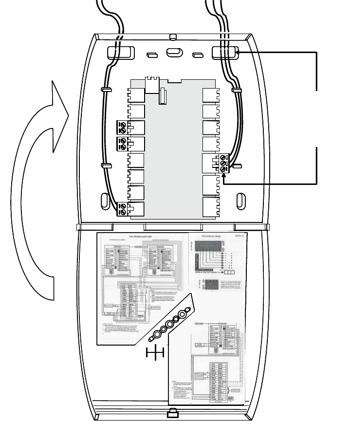
Fig. 13. Internal structure and components of IOM
PRINTED CIRCUIT
BOARD
BACK KNOCK-
OUTS FOR CABLE
HOLES (2)
WIRING
TERMINALS –
2 WIRE (13)
WIRING
TERMINALS –
3 WIRE (3)
IOM FRONT COVER -OPEN
HOLE FOR
TAMPER-
RESISTANT
SCREW
IOM BACK HALF -OPEN
HOLE FOR
TAMPER-
RESISTANT
SCREW
LIGHT GUIDES
CABLE
GUIDES (6)
COVER TAMPER
DETECTION
SWITCH
PULL OPEN THE
FRONT COVER OF
THE IOM AND ALLOW
IT TO HANG FROM
THE HINGE
MOUNTING
SCREW HOLES
(3)
HONEYWELL IDENTIPOINT™ INTELLIGENT SMARTCARD SYSTEM
95-7767 16
Fig. 14. Mounting the IOM on a drywall
CUT OPENINGS IN THE
DRYWALL FOR ROUTING THE
WIRES. THE OPENINGS MUST
HAVE THE SAME DIMENSIONS
AS THAT IN THE BACK HALF OF
THE IOM.
PUNCH THREE HOLES IN
THE DRYWALL FOR THE
SCREWS
USE THE SCREWS
PROVIDED TO FIX THE
BACK HALF OF THE IOM
TO THE DRYWALL.
NOTE: USE ALL THREE
HOLES TO FASTEN THE
IOM
IOM
HONEYWELL IDENTIPOINT™ INTELLIGENT SMARTCARD SYSTEM
17 95-7767
Fig. 15. Mounting the IOM on a concrete wall using gang box and conduit
GANG BOX EMBEDDED IN WALL
PUNCH ADDITIONAL HOLES
IN THE WALL FOR THE
OTHER SCREWS
USE THE SCREWS PROVIDED
TO FIX THE BACK HALF OF IOM
TO THE GANG BOX AND THE
WALL.
NOTE: USE ALL 3 SCREWS TO
FASTEN THE IOM
HONEYWELL IDENTIPOINT™ INTELLIGENT SMARTCARD SYSTEM
95-7767 18
Fig. 16. Routing the wires and connecting them to the IOM PCB
ROUTE THE WIRES
THROUGH THE KNOCK -
OUT HOLES AND FIX
THEM TO THE CORRECT
TERMINALS ON THE PCB
USING THE PROVIDED
WIRE TERMINAL BLOCKS
AFTER WIRING AND
OTHER HARDWARE
CONFIGURATIONS ARE
DONE, SHUT THE FRONT
COVER OF THE IOM
ROUTE THE WIRES
THROUGH THE KNOCK -
OUT HOLES AND FIX
THEM TO THE CORRECT
TERMINALS ON THE PCB
USING THE PROVIDED
WIRE TERMINAL BLOCKS
AFTER WIRING AND
OTHER HARDWARE
CONFIGURATIONS ARE
DONE, SHUT THE FRONT
COVER OF THE IOM

HONEYWELL IDENTIPOINT™ INTELLIGENT SMARTCARD SYSTEM
19 95-7767
Fig. 17. Securing the front cover onto the back half of the IOM
Power
Data
Tamper
USE THE ALLEN
WRENCH TO
SECURE THE FRONT
COVER OF THE IOM
TO THE BACK HALF
WITH TAMPER-
RESISTANT SCREW
Power
Data
Tamper
Power
Data
Tamper
USE THE ALLEN
WRENCH TO
SECURE THE FRONT
COVER OF THE IOM
TO THE BACK HALF
WITH TAMPER-
RESISTANT SCREW
HONEYWELL IDENTIPOINT™ INTELLIGENT SMARTCARD SYSTEM
95-7767 20
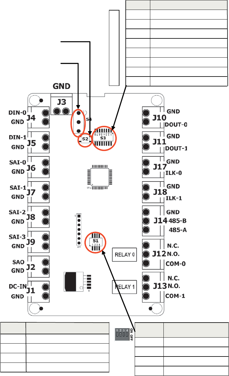
Fig. 18. IOM connections
DIP switch -S1
Posion Effect when “ON”
(Posion Up)
1 RS485-A pull up
2 RS485 terminaon
3 RS485-B pull down
4Reserved
Posion Effect when “ON”
(Posion Up)
1 RS485-A pull up
2 RS485 terminaon
3 RS485-B pull down
4Reserved
Switch Descripon
S1 RS485 Terminaon Control DIP switch
S2 Inializaon Buon
S3 IOM Address set up DIP switch
S4 Cover tamper detecon switch
Switch Descripon
S1 RS485 Terminaon Control DIP switch
S2 Inializaon Buon
S3 IOM Address set up DIP switch
S4 Cover tamper detecon switch
S2: Inializaon
Buon
DIP switch
S3 -IOM address
Posion Descripon
1 Address value 1
2 Address value 2
3 Address value 4
4 Address value 8
5 Address value 16
6 Address value 32
7 Address value 64
8 For IOM setup, normally set to OFF
Posion Descripon
1 Address value 1
2 Address value 2
3 Address value 4
4 Address value 8
5 Address value 16
6 Address value 32
7 Address value 64
8 For IOM setup, normally set to OFF
S4: Cover tamper
detecon switch

HONEYWELL IDENTIPOINT™ INTELLIGENT SMARTCARD SYSTEM
21 95-7767
Mounting and Installing the Power
Supply
WARNING
Personal injury or death could occur and the
equipment could be damaged beyond repair if this
precaution is not observed!
— Before installation, turn off the external circuit
breaker which supplies power to the system,
including door locks.
— Before connecting the device to the power supply,
verify that the output voltage is within specifica-
tions of the power supply.
— Do not apply power to the system until after the
installation has been completed.
Power Supply Recommendations
FOR READERS
DC Power Supply:
• Power must be provided to the IdentIPoint readers from a
UL294 and/or UL1076 listed power supply for access
control or one approved by local authority having
jurisdiction.
• Power supply should be 12-24VDC.
• When powered by an external DC source such as the
above, IdentIPoint readers provide a power output for
powering devices like the IOM or a door strike. The max
current provided by the reader in this case is 300mA at 1.5
V less than the input voltage.
• The IdentIPoint readers consume a maximum of 12W
power when supplying power to IOMs and/or other external
devices such as a door strike or magnetic lock relay.
• Any UL Security listed power supply may be used such as
the Honeywell HP400ULPD8CB power supply.
NOTE: For UL294 installations, only UL294 and/or
UL1076 listed power supplies should be used for
reader and lock power with required 72 hour bat-
tery backup.
Power-over-Ethernet
1. If Power-over-Ethernet (PoE) devices are used to power
the IdentIPoint readers, they must conform to the IEEE
802.3af standard. See section Power over Ethernet
(PoE) wiring of Wiring the Readers and IOM topic for
details on selecting PoE devices.
2. When powered by an IEEE802.3af compliant PSE
(Power Supply Equipment), IdentIPoint readers provide
a power output for powering devices like the IOM or a
door strike. The max current provided by the reader in
this case is 300mA at 10.5VDC.
3. The IdentIPoint readers consume a maximum of 12W
power when supplying power to IOMs and/or other
external devices such as a door strike or magnetic lock
relay.
4. Where it is not feasible to use PoE switches, PoE mid-
spans may be alternatively used.
NOTE: Use of PoE is not a UL294 listed configuration
and should not be used on projects where a
UL294 certificate will be issued.
FOR IOM
1. Power must be provided to the IdentIPoint IOM from a
UL294 and/or UL1076 listed power supply for access
control or one approved by local authority having juris-
diction.
2. Power supply for IOM should be 12-24VDC.
3. Power consumption is 1.2W max.
NOTE: For UL294 installations, only UL294 and/or
UL1076 listed power supplies should be used for
reader and lock power with required 72 hour bat-
tery backup.
Circuit Protection for Readers and IOM
1. IdentIPoint readers and the IOM are able to withstand
power on wrong terminal up to 24VDC on any of the
exposed terminals of the reader.
2. IdentIPoint readers and the IOM are able to withstand
power connection of up to 24VDC with reverse polarity.
3. IdentIPoint readers and IOM are able to withstand I/O
short circuit on all inputs and outputs.
Installation Instructions
1. Mounting: The power supply should be installed in
accordance with all applicable codes and standards.
2. Power Supply Input Connection: Before connecting
power review the entire wiring diagram provided with the
power supply for correct installation. Make input con-
nections as instructed in the manual provided with the
power supply.
NOTE: For countries that use input voltage other than
120VAC, check the available literature on the
power supply for details on configuring the
power supply to accept 230VAC input voltage.
3. Output Connections: Connect the power supply outputs
to the desired devices observing polarity. See Table.2
for wire sizes and distances.
WARNING
To reduce risk of electric shock, do not expose
unit to rain or excess moisture, and disconnect
power before servicing unit. For continuous
protection against hazards, replace fuses only
with exact type and rating. A readily accessible
switched circuit breaker must be available to
disconnect main power as required. All 120V
wiring should be routed so that it cannot touch
24V wiring; minimum spacing 3/8" (0.953cm).
Installation and servicing should only be made by
qualified personnel; contains no user-serviceable
parts. Install in accordance with all local
regulations and the National Electrical Code.
Maintenance
The power supply unit should be tested at least once a year to
verify correct operation in accordance with the following
recommendations:
Output Voltage Test - Voltage output should be tested under
normal load conditions to verify correct levels.
Battery Test - Battery should be checked for full charge under
normal load conditions. This check should verify correct
voltage at both battery terminals and also at the battery output

HONEYWELL IDENTIPOINT™ INTELLIGENT SMARTCARD SYSTEM
95-7767 22
point on the board to ensure the integrity of all connecting
wiring. The battery should be replaced every 4 years or more
often under severe conditions.
WIRING THE READERS AND
IOM
General Descriptions
Power to the Reader:
Power can be supplied to the IdentIPoint reader either via the
Ethernet cable when it is connected to a router/switch that is
equipped with PoE (Power over Ethernet) PSE (Power Supply
Equipment) feature, or through a 12-24VDC power source.
NOTE: The PoE PSE can supply power up to 12.95 Watt.
It can supply power for one reader, one door
strike/magnetic lock which consumes a steady
current of less than 300mA (e.g. ASSA ABLOY
HES 5200) and one IOM. For the IOM module, DC
12V is needed.
Use of PoE is not a UL294 listed configuration and should not
be used on UL294 applications.
Data Communication:
Each IdentIPoint reader is equipped with an RJ45 connector
for Ethernet communication. It also has a wireless LAN
module that supports IEEE802.11b/g. The reader can
communicate with one or more IOMs via the RS485 bus.
NOTE: Wifi network configuration is not a UL294 listed
configuration and should not be used on UL294
applications.
The RS485 bus is a multi-drop 2-wire bus running differential
signal in half duplex. A third wire, the common ground, is also
recommended for more reliable communication. Multiple IOM
units can be attached to an IdentIPoint reader through this bus
in daisy chain mode. See Fig.24.
NOTE: It is recommended not to attach more than 4 IOM
units to the RS485 bus to maintain a reasonable
signal/response time delay between the reader
and IOMs.
CAUTION
Transmission Protection The system may require
external lightning protection. For details, refer to
Lightning Protection topic.
Supervised Analog Input (SAI):
The Supervised Analog Input is designed to detect
supervisory loop tamper. See section Supervisory Analog
Input (SAI) termination circuit of Wiring Other Devices topic for
details. Such a loop circuit can be connected to the SAI of an
IdentIPoint reader as well as the IOM. This loop can detect
tampering by shorting across or cutting the loop. Four states
can be detected by the IdentIPoint device: open, short, cut
and closed.
Digital Input (DI) (IOM only):
The Digital Input is an active high input, which can be read by
the IOM and reported back to the reader through the RS485
interface.
Digital Output (DO)
The Digital Output is a current sinking output, capable of
sinking up to 1A at the rated supply voltage. The output can
thus be used to drive the door strike/magnetic lock, lights as
well as other Digital Inputs or Supervisory Inputs. See Figures
25 through 28.
Wire the Readers and IOM
1. Run the field wiring to the readers as per the job draw-
ings. Figures 21 through 24 show typical wiring
schemes for IdentIPoint devices. Wires of a minimum
gauge of 18 AWG are recommended for all wiring with
the upper limits specified for some applications. See
Table.2 for details on wire sizes and maximum permissi-
ble distances. 18 AWG wires (0.3 sq. mm) must be lim-
ited to 1A loading. When used for carrying
communication data as in RS485, the wires must be a
twisted pair.
2. To power the reader, plug the Molex terminal into the J9
port of the reader such that the red and black wires of
the terminal, connected to the +ve and -ve pins of the
power supply connect with pins 1 (Power IN) and 2
(Power GND) of the J9 port.
3. Ensure the other wires of the Molex terminal are con-
nected to the correct corresponding wires from the other
devices such as IOMs, door sensors, door strikes etc.
(see Detailed Wiring Diagrams and Wiring Other
Devices topics and Fig.11). For wires that are not used,
ensure proper insulation at the free ends.
4. To power the IOM, plug the terminal block into the J1
port of the IOM such that the wires connected to the +ve
and -ve pins of the power supply, connect with the pins
for DC-IN and GND of the J1 port. The IOM may also be
alternatively powered through an IdentIPoint reader
(see Fig.22).
5. Ensure the other ports of the IOM are similarly con-
nected to the correct corresponding wires from the other
devices such as readers, door sensors, door strikes etc.
(See Detailed Wiring Diagrams and Wiring Other
Devices topics and Fig.18).
6. Use proper crimping and/or insulation while connecting
the wires.
Grounding Recommendations
The FRAME-GROUND signal (pin 10 of J10) of the reader
has to be connected to the POWER-GND at all times to
ensure good ESD protection and low electromagnetic
radiation.
The FRAME-GROUND signal (port J3) of the IOM has to be
connected to the POWER-GND before making any other
connections to minimize the introduction of error in the RS485
communication line during hot signal insertion. It also should
be the last signal to be disconnected.
NOTE: FRAME-GROUND is also known as CHASSIS-
GROUND in some countries including USA.

HONEYWELL IDENTIPOINT™ INTELLIGENT SMARTCARD SYSTEM
23 95-7767
Power Wiring
IMPORTANT
Use a shielded power cable with a three-pin (or as
per local regulations) plug to draw mains power for
the power supply assembly. (The shielded wire is
required to meet FCC RF radiation limits.)
To route the power wiring
1. Using proper conduits, route the input power cable from
the mains supply to the input block of the power supply.
2. Route the +ve and -ve pairs of wires from the output
block of the power supply out of the power supply enclo-
sure via proper conduits.
3. Connect the +ve and -ve of wires to IdentIPoint devices.
For readers, connect the +ve to the red and the -ve to
the black wires of the 9-pin Molex terminal respectively.
(See Fig.6 for details on Molex terminal wire colors.)
Tamper Protection
IMPORTANT
IdentIPoint readers are equipped with tamper protec-
tion features. They must be permanently mounted
before commissioning. Attempting to open a reader
case without putting it in maintenance mode will dis-
able the reader, and require recommissioning. For
details on how to deal with a tampered reader please
refer the EBI documentation set.
Table 2. Wire Sizes and Distances
EACH DOOR STRIKE REQUIRES A 14507020-001 DIODE
SUPPRESSION NETWORK. DOOR STRIKE MAY DRAW A
MAXIMUM CURRENT OF 2A; REGULATED 12/ 24 VDC.
DOOR STRIKE AND REX MUST BE UL LISTED. SEE
FIG.25 THROUGH FIG.28 FOR TYPICAL DIODE SUP-
PRESSION NETWORK WIRING.
DOOR CONTACTS MUST BE UL LISTED. MAXIMUM WIRE
LENGTH 500 FT (152 M). WIRE TYPE 18 AWG (0.8 SQ
MM), 50 OHM 60 mA MAXIMUM. DOOR CONTACTS ARE
ONLY INTENDED FOR MONITORING DOOR POSITION.
THEY ARE NOT INTENDED FOR CONNECTION TO A
BURGLAR ALARM PANEL
EXIT SWITCH: WIRING MUST BE COMPLETED WITHIN
THE PROTECTED AREA OR NOT READILY ACCESSIBLE
OUTSIDE THE PROTECTED AREA. THE EXIT SWITCH
MUST BE UL LISTED.
Connection Wire Gauge Maximum Distance
Minimum
number of
conductors Shielding
Power Source to
Device (Reader
or IOM)
18 AWG
(0.8mm2) to 15
AWG (1.7mm2)
See reader/IOM power requirements
(section Power Supply Recommendations
of Assembly, Mounting and Installation
topic) and compensate for drop in voltage.
3 Unshielded
cable
recommended
Reader/IOM to
Digital Inputs
18 AWG
(0.8mm2)
100m 2 per i/p Optional
Reader/IOM to
Digital Output or
Lock
18 AWG
(0.8mm2) to 15
AWG (1.7mm2)
100m subject to adequate power reaching
the output device or lock
2 per o/p Required for
power cable
connected to
output device or
lock
Reader to IOM
(Power)
18 AWG
(0.8mm2) to 15
AWG (1.7mm2)
See IOM power requirements (section
Power Supply Recommendations of
Assembly, Mounting and Installation topic)
and compensate for drop in voltage.
2 Required
Reader to IOM
(RS485 comm.)
18 AWG
(0.8mm2)
500m 3 Recommended
Reader to IOM
(other than Power
and RS485
comm.)
18 AWG
(0.8mm2)
100m 2 per connection
type
Optional
IOM to IOM
(RS485 comm.)
18 AWG
(0.8mm2)
500m 3 Recommended
Ethernet CAT5 100m Standard as in
CAT5
Recommended
HONEYWELL IDENTIPOINT™ INTELLIGENT SMARTCARD SYSTEM
95-7767 24
ALL WIRING MUST CONFORM TO APPLICABLE LOCAL
CODES, ORDINANCES, AND REGULATIONS.
DO NOT ROUTE COMMUNICATION WIRES WITH POWER
OR LOCKING DEVICES.
NOTE: FOR COMMUNICATION CIRCUITS AND OTHER
APPLICABLE WIRING CIRCUITS WHERE WIRING
ENTERS AND EXITS THE BUILDING, REFER TO
TABLE 13 FOR APPROPRIATE LIGHTNING PRO-
TECTOR USAGE.
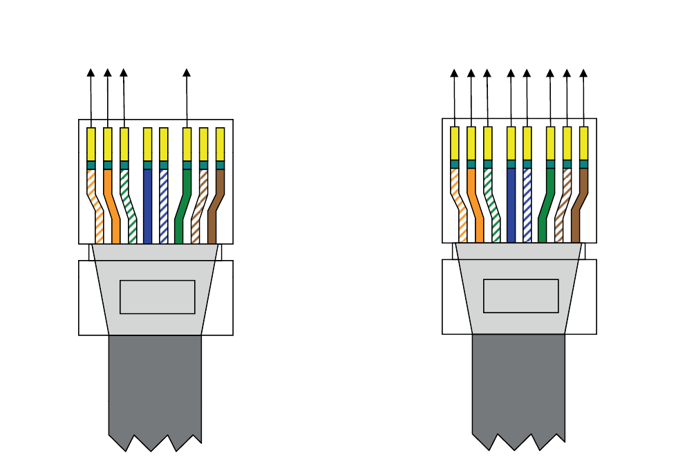
Power over Ethernet (PoE) wiring
PoE integrates data and power on the same wires, without interfering with concurrent network operation. PoE delivers 48V of DC
power over unshielded twisted-pair wiring for terminals consuming less than 13 watts of power.
PoE can be used with IEEE 802.3af compliant devices in either of the two modes described in Table.3 and shown in Fig.19 and
Fig.20. The detailed pin-outs are shown in Table.4.
Fig. 19. Straight cable pinouts for PoE in Mode A Fig. 20. Straight cable pinouts for PoE in Mode B
Rc+
Rc-
Tx+
Tx-
,
8 NIP1 NIP
, DC+
, DC+
, DC-
,
DC-
PIN 1 PIN 8
Rc+
Rc-
Tx+
Tx-
DC+
DC+
DC-
DC-

HONEYWELL IDENTIPOINT™ INTELLIGENT SMARTCARD SYSTEM
25 95-7767
Table 3. PoE Modes
Table 4. PoE pin-outs for the two modes.
NOTE: Use of PoE is not a UL294 listed configuration and should not be used on UL294 applications.
Pin Model A Model B
1 Vport positive
2 Vport positive
3 Vport negative
4 Vport positive
5 Vport positive
6 Vport negative
7 Vport negative
8 Vport negative
STANDARD SOURCE LOAD REMARKS
Ethernet RJ-45 connector pin number
Source
Voltage
1 2 3 4 5 6 7 8 Load
Voltage
DC Load
Connector
IEEE
802.3af
using data
pairs
48 V DC
protected
RX
DC
+
RX
DC
+
TX
DC-
spare spare TX-
DC
spare spare (embedded) Industry
standard
for
embedded
PoF
IEEE
802.3af
using spare
pairs
48 V DC
protected
RX RX TX DC + DC + TX DC - DC - (embedded) Industry
standard
for
embedded
PoF
HONEYWELL IDENTIPOINT™ INTELLIGENT SMARTCARD SYSTEM
95-7767 26
DETAILED WIRING DIAGRAMS
Single Reader with REX and without IOM
Fig. 21. Connections for single reader with REX and without IOM
In the above configuration, one IdentIPoint reader operates in
stand-alone mode to control door access. It authenticates
users as well as releases the door lock using its relay contact.
Minimum Connections:
1. Connect the Ethernet/PoE cable to the RJ45 port of the
reader through the CAT5 pigtail. (Frame-GND connec-
tion to building GROUND Earth is recommended for
better electro-static discharge resilience.) See Fig.7.
2. If PoE switch is not used, connect a 12-24VDC power
supply to pins 1-2 (Power-IN - Power-GND) of port J9 of
the reader. See section Wire the Readers and IOM of
Wiring the Readers and IOM topic for details on power
supply connections.
3. Connect pin(s) 3/4/5 (Relay-C/Relay-NC/Relay-NO) of
port J9 to the door lock depending on the type of lock
(magnetic lock or door strike) used and the safety codes
to be followed. Also connect a power line to the lock.
See Wiring Other Devices topic for detailed wiring of
locks.
4. Connect pins 6-7 (SAI-0 - SAI-0-GND) and 8-9 (SAI-1 -
SAI-1-GND) to a Request-to-Exit (REX) switch and door
sensor with proper termination circuit as described in
section Supervisory Analog Input (SAI) termination cir-
cuit of Wiring Other Devices topic. An additional sensor
can be connected to SAI-2 of port J10.
To Door Sensor Power-OUT
SAI-1-GND
Power-GND
SAI-1 82
91
J10PINPINJ9
To LAN Ethernet
2KΩ 1KΩ
DC
–
Power
2KΩ 1KΩ
2
8
3
RS485-A
SAI-0-GND
7
4
RS485-B
SAI-0
6
5RS485-GND
5ON-yaleR
6
DO
Relay-NC
4
7
DOGnd
Relay-C
3
SAI
-
2
Power
-
GND
To Door Lock
To REX Switch
DC
Power
12 to 24V
If PoE is not used. 19
2
8
SAI
2
Power
GND
SAI-2-GND
Power-IN
Frame-GND
10
To electrical
earth.
If unavailable,
connect to
Power-GND.
S1
IdentIPoint Reader
Power – Min. 18 AWG
Power Gnd – Min. 18 AWG
Ethernet – CAT5
Signal/Power – Min. 18 AWG
Signal
–
Min 18 AWG
LEGEND
Signal
Min
.
18 AWG
Signal – Min. 18 AWG
HONEYWELL IDENTIPOINT™ INTELLIGENT SMARTCARD SYSTEM
27 95-7767
NOTE: REX and Door Sense support only Normally
Closed and not Normally Open positions, i.e.,
REX is detected when SAI switch is open, Door is
sensed as open when SAI switch is open.
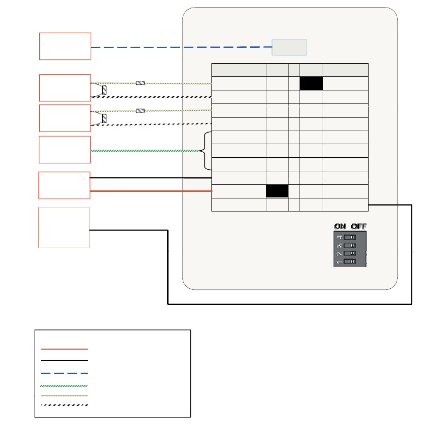
Single Reader with REX and IOM
Fig. 22. Connections for single reader with REX and IOM (S1 DIP switch settings shown)
Ethernet
To LAN
J10PINJ9 PIN
Power-OUT
SAI-1-GND
Power-GND
SAI-1
RS485-A
SAI-0-GND
RS485-B
SAI-0
5RS485-GND
Relay-NO
6
7
8
9
5
4
3
2
1
1
2
3
4DO
Relay-NC
DOGnd
Relay-C
SAI-2
Power-GND
SAI-2-GND
Power-IN
Frame-GND
9
8
7
6
10
DC – Power
12 to 24V
If PoE is not used
To electrical
earth
IdentIPoint Reader S1
earth
.
If unavailable,
connect to
Power-GND.
DI-0 GND
GND DO-0
DI-1 GND
Power – Min. 18 AWG
Power Gnd – Min. 18 AWG
Ethernet – CAT5
LEGEND
GND DO-1
SAI-0 GND
GND ILK-0
SAI-1 GND
GND ILK-1
SAI
-
2
485
-
1KΩ
To REX Switch
1KΩ
To Door Sensor
Signal/Power
–
Min. 18 AWG
Signal – Min. 18 AWG
Signal – Min. 18 AWG
Comm. – Min. 18 AWG
Comm. – Min. 18 AWG
Comm. – Min. 18 AWG
2KΩ
2KΩ
To Door Lock
SAI
2
485
GND
GND 485-B
SAI-3 485-A
GND N.C
SAO N.O
GND
RL0
C
Separate Power Supply
can also be used for IOM.
To electrical
earth.
If unavailable,
GND
RL0
-
C
12V N.C
GND N.O
FGND RL1-C
IO Module S1
connect to
Power-GND.
HONEYWELL IDENTIPOINT™ INTELLIGENT SMARTCARD SYSTEM
95-7767 28
In the above configuration, one IdentIPoint reader and one
IOM are connected through a secure RS485 connection to
control door access. While the IdentIPoint reader
authenticates users, the IOM releases the door lock upon the
reader's command. A Request-to-Exit (REX) switch can be
connected to the IOM's Digital Input or Supervised Analog
Input (SAI). The reader can read the state of the REX switch
and give instructions to the IOM regarding the door.
Minimum Connections:
1. Connect the Ethernet/PoE cable to the RJ45 port of the
reader through the CAT5 pigtail. (Frame-GND connec-
tion to building GROUND Earth is recommended for
better electro-static discharge resilience.) See Fig.7.
2. If PoE switch is not used, connect a 12-24VDC power
supply to pins 1-2 (Power-IN - Power-GND) of port J9 of
the reader. See section Wire the Readers and IOM of
Wiring the Readers and IOM topic for details on power
supply connections.
3. Connect the RS485-A, RS485-B and RS485-GND (pins
3, 4 and 5 on port J10 of the reader) to their correspond-
ing RS485 points on J14 of the IOM. See section
RS485 Communication and Termination Setting of Con-
nector and Switch Descriptions topic for details on
RS485 wiring and termination settings. Set the S1 DIP
switch on the reader and the IOM accordingly.
4. Power to the IOM can be given by connecting the
Power-OUT - Power-GND (pins 1-2 on J10) of the
reader to 12V - GND (J1) respectively of the IOM. Alter-
natively, power to the IOM can also be supplied through
a separate 12-24VDC power supply or a common rail.
5. Connect pin(s) NC/NO/RL0-C or RL1-C (J12/J13) of the
IOM to the door lock depending on the type (magnetic
lock or door strike) used and the safety codes to be fol-
lowed. Also connect a power line to the lock. Detailed
wiring for locks is shown in Wiring Other Devices topic.
6. Connect J6, J7, J8 or J9 of the IOM (SAI-n - SAI-n-
GND) to a door sensor and a REX switch with proper
termination circuit as described in section Supervisory
Analog Input (SAI) termination circuit of Wiring Other
Devices topic. Alternatively, the REX switch can also be
connected to DI-0 - GND or DI-1 - GND (J4 or J5) of the
IOM without any termination circuit.
NOTE:
• The IOM must be installed on the secure side of the
door.
• The RS485 ground signal is not necessary if the IOM
is powered by the IdentIPoint reader or if there is a
common ground available between the two units.
• REX and Door Sense support only Normally Closed
and not Normally Open positions, i.e., REX is
detected when SAI switch is open, Door is sensed as
open when SAI switch is open.
HONEYWELL IDENTIPOINT™ INTELLIGENT SMARTCARD SYSTEM
29 95-7767
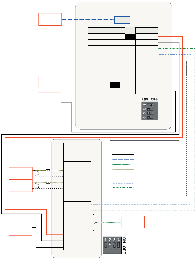
Two Readers with IOM
Fig. 23. Connections for two readers with IOM (S1 DIP switch settings shown)
Power – Min. 18 AWG
Power Gnd–Min. 18 AWG
Ethernet – CAT5
Signal – Min. 18 AWG
Signal – Min. 18 AWG
Comm. – Min. 18 AWG
Comm. – Min. 18 AWG
Comm. – Min. 18 AWG
Comm. – Min. 18 AWG
LEGEND
Comm. – Min. 18 AWG
Ethernet
IdentIPoint Reader
S1
RL1-C
N.OGND
N.C12V
RL0 -CGND
N.OSAO
N.CGND
485-ASAI-3
485-BGND
485-
GND
SAI-2
ILK-1GND
GNDSAI-1
ILK-0GND
GND
SAI-0
GND
GND
DO-0GND
GND
RL1-C
N.OGND
N.C12V
CGND
N.OSAO
N.CGND
485-ASAI-3
485-BGND
485-
GND
SAI-2
ILK-1GND
GNDSAI-1
ILK-0GND
GND
SAI-0
GND
GNDDI-1
DO-0GND
GNDDI-0
IO module
S1
To Door Sensor
FGND
DC –Power
12 to 24V
If PoE is not used.
DC –Power
12 to 24V
If PoE is not used.
DO-1DO-
To LAN
To electrical earth.
If unavailable, connect
to Power-GND.
To electrical earth.
If unavailable, connect
to Power-GND.
Connecons on Out-s
no
itc
e
n
noCre
d
a
e
r on In-reader
Ethernet
IdentIPoint Reader
S1
DC – Power
12 to 24V
If PoE is not used.
To electrical earth.
If unavailable, connect
to Power-GND.
1KΩ
2KΩ
2KΩ
1KΩ
* 1KΩ for 12V
2KΩ for 24V
Secure deru
ces
n
Ued
i
S Side
To EML
Door Lock
1
Power-OUT
SAI-1-GND
2
Power-GND
SAI-1
3
RS485-A
SAI-0-GND
4
RS485-B
SAI-0
5RS485-GND
Relay-NO
6
DO
Relay-NC
7
DOGnd
Relay-C
8
SAI-2
Power-GND
9
SAI-2-GND
Power-IN
Frame-GND
J10PIN
J9
9
8
7
6
5
4
3
2
1
PIN
10
9
8
7
6
5
4
3
2
1
PIN
10
1
Power-OUT
SAI-1-GND
2
Power-GND
SAI-1
3
RS485-A
SAI-0-GND
4
RS485-B
SAI-0
5RS485-GND
Relay-NO
6
DO
Relay-NC
7
DOGnd
Relay-C
8
SAI-2
Power-GND
9
SAI-2-GND
Power-IN
Frame-GND
J10PIN
J9
9
8
7
6
5
4
3
2
1
PIN
10
9
8
7
6
5
4
3
2
1
PIN
10
* Can also internally connect
12V to RL0-C
HONEYWELL IDENTIPOINT™ INTELLIGENT SMARTCARD SYSTEM
95-7767 30
In the above configuration, two IdentIPoint readers and one
IOM are inter-connected to control an IN/OUT door. While the
IdentIPoint readers authenticate users on both sides of the
door, the IOM releases the door lock upon the readers'
commands. A Request-to-Exit (REX) button is not required in
this setup.
Minimum Connections:
1. Connect the Ethernet/PoE cable to the RJ45 port of the
reader through the CAT5 pigtail. (Frame-GND connec-
tion to building GROUND Earth is recommended for
better electro-static discharge resilience.) See Fig.7.
2. If PoE switch is not used, connect a 12-24VDC power
supply to pins 1-2 (Power-IN - Power-GND) of port J9 of
the reader and pins 12V - GND (J1) of the IOM through
a common rail. This is the recommended power supply
configuration as it is necessary to provide a common
ground to all three devices. See section Wire the Read-
ers and IOM of Wiring the Readers and IOM topic for
details on power supply connections.
3. Connect the RS485-A, RS485-B and RS485-GND (pins
3, 4 and 5 on port J10 of the In-reader) to their corre-
sponding RS485 points on J14 of the IOM. See section
RS485 Communication and Termination Setting of Con-
nector and Switch Descriptions topic for details on
RS485 wiring and termination settings. Set the S1 DIP
switch on the In-reader and the IOM accordingly.
4. Connect pin(s) NC/NO/RL0-C or RL1-C (J12/J13) of the
IOM to the door lock depending on the type (magnetic
lock or door strike) used and the safety codes to be fol-
lowed. Also connect a power line to the lock. Detailed
wiring for locks is shown in Wiring Other Devices topic.
5. Connect J6, J7, J8 or J9 of the IOM (SAI-n - SAI-n-
GND) to a door sensor with proper termination circuit as
described in section Supervisory Analog Input (SAI) ter-
mination circuit of Wiring Other Devices topic.
6. Make all other interconnections between the Out-reader
and IOM as shown in Fig. 23.
NOTE:
• The Out-reader must be installed on the secure side
of the door along with the IOM.
• For a single door controlled by two readers with IOM
the door sensor shall always be wired to SAI-3 of the
IOM.
• The RS485 ground signal is not necessary if the IOM
is powered by the IdentIPoint reader or if there is a
common ground available between the two units.
• The resistors need to be connected at proper
terminals as shown in the diagram.
• REX and Door Sense support only Normally Closed
and not Normally Open positions, i.e., REX is
detected when SAI switch is open, Door is sensed as
open when SAI switch is open.
HONEYWELL IDENTIPOINT™ INTELLIGENT SMARTCARD SYSTEM
31 95-7767
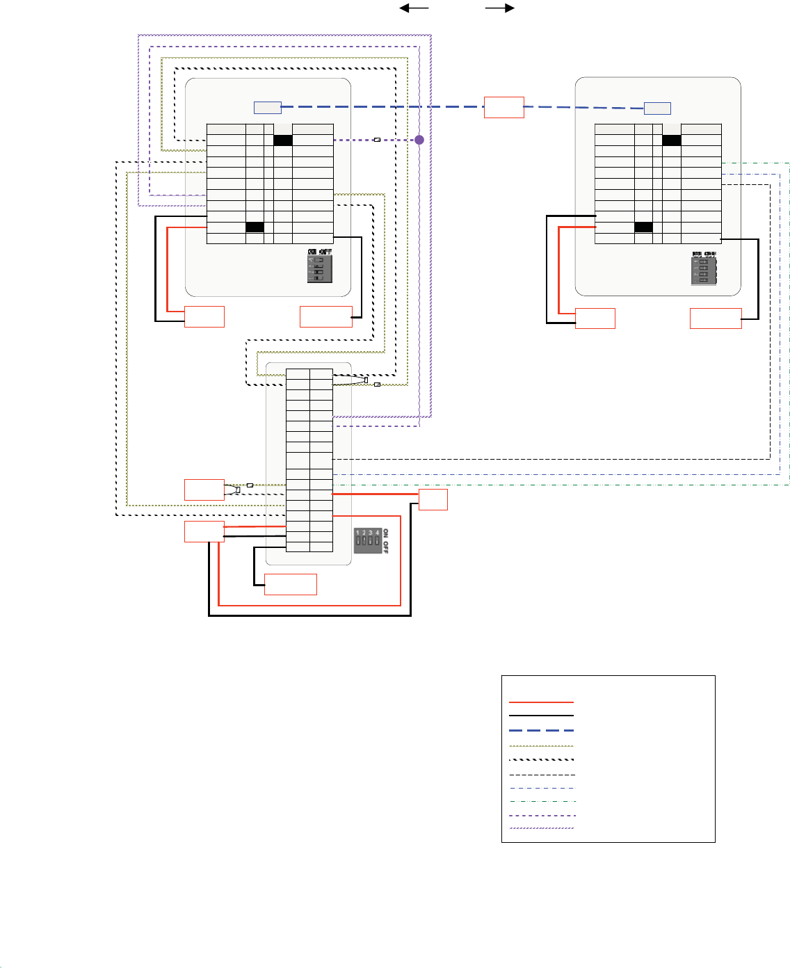
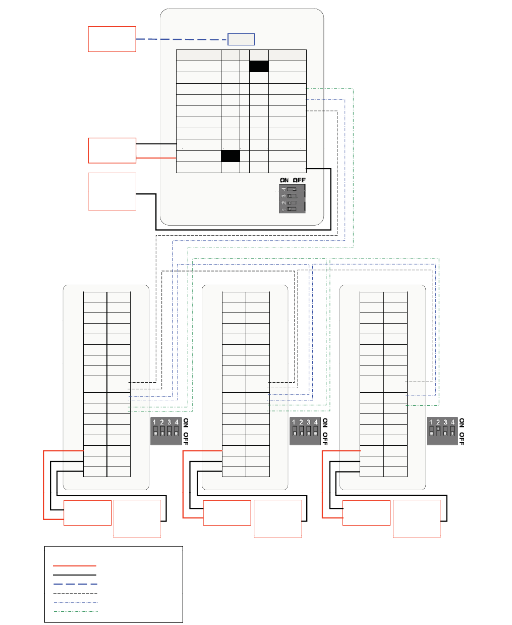
Reader with Multiple IOMs
Fig. 24. Connections for reader with three IOMs on a RS485 bus (S1 DIP switch settings shown)
J9
PINPINJ10
Ethernet
J9
PINPINJ10
Ethernet
J10PINPINJ9
To LAN
Relay-NC47DOGnd
Relay-C38SAI-2
Power-GND2
9
SAI-2-GND
Power-IN
1
10Frame-GND
Relay-NC47DOGnd
Relay-C38SAI-2
Power-GND2
9
SAI-2-GND
Power-IN
1
10Frame-GND
Power-OUT
SAI-1-GND
Power-GND
SAI-1
RS485-A
SAI-0-GND
RS485-B
SAI-0 64
73
82
91
–
DC – Power
SAI
1
GND
9
2
P
GND
SAI-183RS485-A
SAI-0-GND74RS485-B
SAI-065RS485-GND
Relay-NO
56DO
SAI
1
GND
9
2
P
GND
SAI-183RS485-A
SAI-0-GND74RS485-B
SAI-065RS485-GND
Relay-NO
56DO
28
37
46
5RS485-GND
5ON-
y
a
l
eR
DO
Relay-NC
DOGnd
Relay-C
SAI-2
Power-GND
12 to 24V
If PoE is not used.
1Power-OUT
SAI
-
1
-
GND
9
2
P
ower-
GND
1
2
OFF ON
1Power-OUT
SAI
-
1
-
GND
9
2
P
ower-
GND
1
2
OFF ON
19SAI-2-GND
Power-IN
Frame-GND
10
To electrical
earth.
If unavailable
S1
2
3
4
BOTAC reader
S1
2
3
4
BOTAC reader
IdentIPoint Reader S1
If
unavailable
,
connect to
Power-GND.
GNDDI-1
DO-0GND
GNDDI-0
GNDDI-1
DO-0GND
GNDDI-0
GNDDI-1
DO-0GND
GNDDI-0
GNDDI-1
DO-0GND
GNDDI-0
GNDDI-1
DO-0GND
GNDDI-0
GNDDI-1
DO-0GND
GNDDI-0
GNDSAI-1
ILK-0GND
GND
SAI-0
D1-0GND
GNDSAI-1
ILK-0GND
GND
SAI-0
D1-0GND
GNDSAI-1
ILK-0GND
GND
SAI-0
D1-0GND
GNDSAI-1
ILK-0GND
GND
SAI-0
D1-0GND
GNDSAI-1
ILK-0GND
GND
SAI-0
D1-0GND
GNDSAI-1
ILK-0GND
GND
SAI-0
D1-0GND
DO-1 DO-1 DO-1
485-BGND
485-
GND
SAI-2
ILK-1GND
485-BGND
485-
GND
SAI-2
ILK-1GND
485-BGND
485-
GND
SAI-2
ILK-1GND
485-BGND
485-
GND
SAI-2
ILK-1GND
485-BGND
485-
GND
SAI-2
ILK-1GND
485-BGND
485-
GND
SAI-2
ILK-1GND
NC
12V
RLO-CGND
N.OSAO
N.C
GND
485-ASAI-3
NC
12V
RLO-CGND
N.OSAO
N.C
GND
485-ASAI-3
NC
12V
RLO-CGND
N.OSAO
N.C
GND
485-ASAI-3
NC
12V
RLO-CGND
N.OSAO
N.C
GND
485-ASAI-3
NC
12V
RLO-CGND
N.OSAO
N.C
GND
485-ASAI-3
NC
12V
RLO-CGND
N.OSAO
N.C
GND
485-ASAI-3
S1
S1
S1
RL1-C
N.OGND
N
.
C
12V
RL1-C
N.OGND
N
.
C
12V
IO module
RL1-C
N.OGND
N
.
C
12V
RL1-C
N.OGND
N
.
C
12V
IO module
RL1-C
N.OGND
N
.
C
12V
RL1-C
N.OGND
N
.
C
12V
IO module
IOM 1 IOM 2 IOM 3
FGND D
N
GFD
NGF
S1
S1
S1
DC – Power
12 to 24V
DC – Power
12 to 24V
DC – Power
12 to 24V
To electrical
earth.
If unavailable,
connect to
Power-GND.
To electrical
earth.
If unavailable,
connect to
Power-GND.
To electrical
earth.
If unavailable,
connect to
Power-GND.
Power – Min. 18 AWG
Power Gnd – Min. 18 AWG
Comm
–
Min 18 AWG
LEGEND
Ethernet – CAT5
Comm
.
Min
.
18
AWG
Comm. – Min. 18 AWG
Comm. – Min. 18 AWG
HONEYWELL IDENTIPOINT™ INTELLIGENT SMARTCARD SYSTEM
95-7767 32
In the above configuration, three IdentIPoint IOMs are inter-
connected with a reader in a master-slave configuration. Such
connections are necessary when a reader needs to connect
with more than one IOM.
Minimum Connections:
1. Connect the RS485-A, RS485-B and RS485-GND (pins
3, 4 and 5 on port J10 of the In-reader) to their corre-
sponding RS485 points on J14 of IOM1. See section
RS485 Communication and Termination Setting of Con-
nector and Switch Descriptions topic on RS485 wiring
and termination settings. Set the S1 DIP switch on the
reader accordingly.
2. Connect the RS485-A, RS485-B and RS485-GND on
J14 of IOM 1 to their corresponding RS485 points on
J14 of IOM2 and similarly connect IOM2 to IOM3 in a
daisy chain. See section RS485 Communication and
Termination Setting of Connector and Switch Descrip-
tions topic for details on RS485 wiring and termination
settings. Set the S1 DIP switch on the IOMs accordingly.
3. Make all other connections between the reader, IOMs
and other devices as needed and explained in section
Single Reader with REX and IOM of Detailed Wiring
Diagrams topic.
NOTE:
• Although, Fig. 24 shows separate power supplies for
all the devices, it is also possible to provide them
power from a single power source as long at it
delivers the required power for all devices.
• The IOMs must be installed on the secure side of the
door.
• The RS485 ground signal is not necessary if the IOM
is powered by the IdentIPoint reader or if there is a
common ground available between the two units.
WIRING OTHER DEVICES
WARNING
Use suppressors on door strikes and magnetic
locks wherever required. Use 14507020-001 diode
suppression network. Honeywell recommends
only DC locks. See Fig.25 through Fig.28 for
typical diode suppression network wiring.
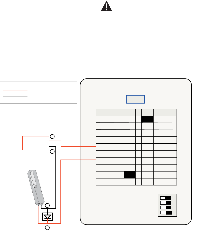
Strike Latch
Strike latch connected directly to the reader:
Fig. 25. Connections between reader and strike latch
Power – Min. 18 AWG
Power Gnd – Min. 18 AWG
LEGEND
Strike Latch
S1
1
2
3
4
OFF ON
Etherne t
IdentIPoint Reader
1
Power-OUT
SAI -1-GND
9
2
Power-GND
SAI -1
8
3
RS485-A
SAI -0-GND
7
4
RS485-B
SAI -0
6
5RS485-GND
Relay-NO 5
6
DO
Relay-NC
4
7
DOGnd
Relay-C
3
8
SAI -2
Power-GND
2
9
SAI -2-GND
Power-IN
1
Frame -GND
J10PINPINJ9
10
DC – Power
12VDC/24VDC
+
_
RED
BLK
_
+
1457020-001
Diode Suppression
Network
Power – Min. 18 AWG
Power Gnd – Min. 18 AWG
LEGEND
Power – Min. 18 AWG
Power Gnd – Min. 18 AWG
LEGEND
Strike Latch
S1
1
2
3
4
OFF ON
Etherne t
IdentIPoint Reader
1
Power-OUT
SAI -1-GND
9
2
Power-GND
SAI -1
8
3
RS485-A
SAI -0-GND
7
4
RS485-B
SAI -0
6
5RS485-GND
Relay-NO 5
6
DO
Relay-NC
4
7
DOGnd
Relay-C
3
8
SAI -2
Power-GND
2
9
SAI -2-GND
Power-IN
1
Frame -GND
J10PINPINJ9
10
S1
1
2
3
4
OFF ON
Etherne t
IdentIPoint Reader
1
Power-OUT
SAI -1-GND
9
2
Power-GND
SAI -1
8
3
RS485-A
SAI -0-GND
7
4
RS485-B
SAI -0
6
5RS485-GND
Relay-NO 5
6
DO
Relay-NC
4
7
DOGnd
Relay-C
3
8
SAI -2
Power-GND
2
9
SAI -2-GND
Power-IN
1
Frame -GND
J10PINPINJ9
10
DC – Power
12VDC/24VDC
++
__
RED
BLK
_
_
++
1457020-001
Diode Suppression
Network
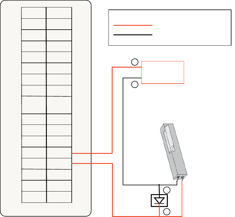
HONEYWELL IDENTIPOINT™ INTELLIGENT SMARTCARD SYSTEM
33 95-7767
1. Connect 12VDC+ of the power supply to pin 5 (Relay-
NO) or pin 3 (Relay-C) of the reader and 12VDC- to the
-ve pin of the strike latch.
2. Connect either pin 5 (Relay-NO) pin 3 (Relay-C), which-
ever is left free, of the reader to the +ve pin of the strike
latch.
In this setup, the door will remain locked in the absence of
power and will be unlocked when power is provided. If the
reader is powered off in this situation, the door will remain
locked.
NOTE: The above describes one way of wiring the strike
latch. Wiring must be done strictly as per the
stipulated safety codes that the building must
follow. Accordingly, the wiring would be either
done in a fail-safe or fail-secure configuration.
For description of reader pins refer to Table.5 and Table.6.
Strike latch connected to the IOM:
Fig. 26. Connections between IOM and strike latch
1. Connect 12VDC+ of the power supply to either the NO
or Common pin of Relay 0 or 1 (J12 or J13) of the IOM,
and the 12VDC- to the -ve pin of the strike latch.
2. In the same port (J12 or J13), connect the NO or Com-
mon, whichever is left free, to the +ve pin of the strike
latch.
In this setup, the door will remain locked in the absence of
power and will be unlocked when power is provided. If the
reader is powered off in this situation, the door will remain
locked.
NOTE: The above describes one way of wiring the strike
latch. Wiring must be done strictly as per the
stipulated safety codes that the building must
follow. Accordingly, the wiring would be either
done in a fail-safe or fail-secure configuration.
For description of IOM pins refer to Table.8.
Power – Min. 18 AWG
Power Gnd – Min. 18 AWG
LEGEND
RL1-C
N.OGND
N.C12V
RLO-CGND
N.OSAO
N.CGND
485-ASAI-3
485-BGND
485-
GND
SAI-2
ILK-1GND
GNDSAI-1
ILK-0GND
GNDSAI-0
DO-1GND
GNDDI-1
DO-0GND
GNDDI-0
IO module
Strike Latch
DC – Power
12VDC/24VDC
FGND
++
__
RED
BLK
_
_
++
1457020-001
Diode Suppression
Network
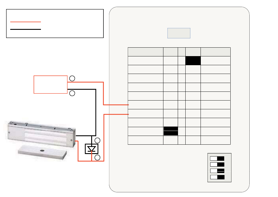
HONEYWELL IDENTIPOINT™ INTELLIGENT SMARTCARD SYSTEM
95-7767 34
Magnetic Lock
Magnetic lock connected directly to the reader:
Fig. 27. Connections between reader and magnetic lock
1. Connect 12VDC+ of the power supply to pin 4 (Relay-
NC) or pin 3 (Relay-C) of the reader and 12VDC- to the
-ve pin of the magnetic lock.
2. Connect either pin 4 (Relay-NC) or pin 3 (Relay-C),
whichever is left free, of the reader to the +ve pin of the
magnetic lock.
In this setup, the door will remain locked as long as power is
provided and will unlock in the absence of power. If the reader
is powered off in this situation, the door will unlock.
NOTE: The above describes one way of wiring the mag-
netic lock. Wiring must be done strictly as per the
stipulated safety codes that the building must
follow. Accordingly, the wiring would be either
done in a fail-safe or fail-secure configuration.
For description of reader pins refer to Table.5 and Table.6.
Power – Min. 18 AWG
Power Gnd – Min. 18 AWG
LEGEND
Ethernet
Power-OUT
SAI-1-GND
Power-GND
SAI-1
RS485-A
SAI-0-GND
RS485-B
SAI-0 64
73
82
91
J10PINPINJ9
DC – Power
12VDC/24VDC
+
Magnetic Lock
1
9
28
37
46
5RS485-GND
5ON-yaleR
DO
Relay-NC
DOGnd
Relay-C
SAI-2
Power-GND
SAI
2
GND
Po er
IN
_
1
2
3
OFF ON
1
9
SAI
-
2
-
GND
Po
w
er
-
IN
Frame-GND
10
1457020-001
Diode Suppression
+
_
RED
BLK
S1
3
4
IdentIPoint Reader
Diode
Suppression
Network
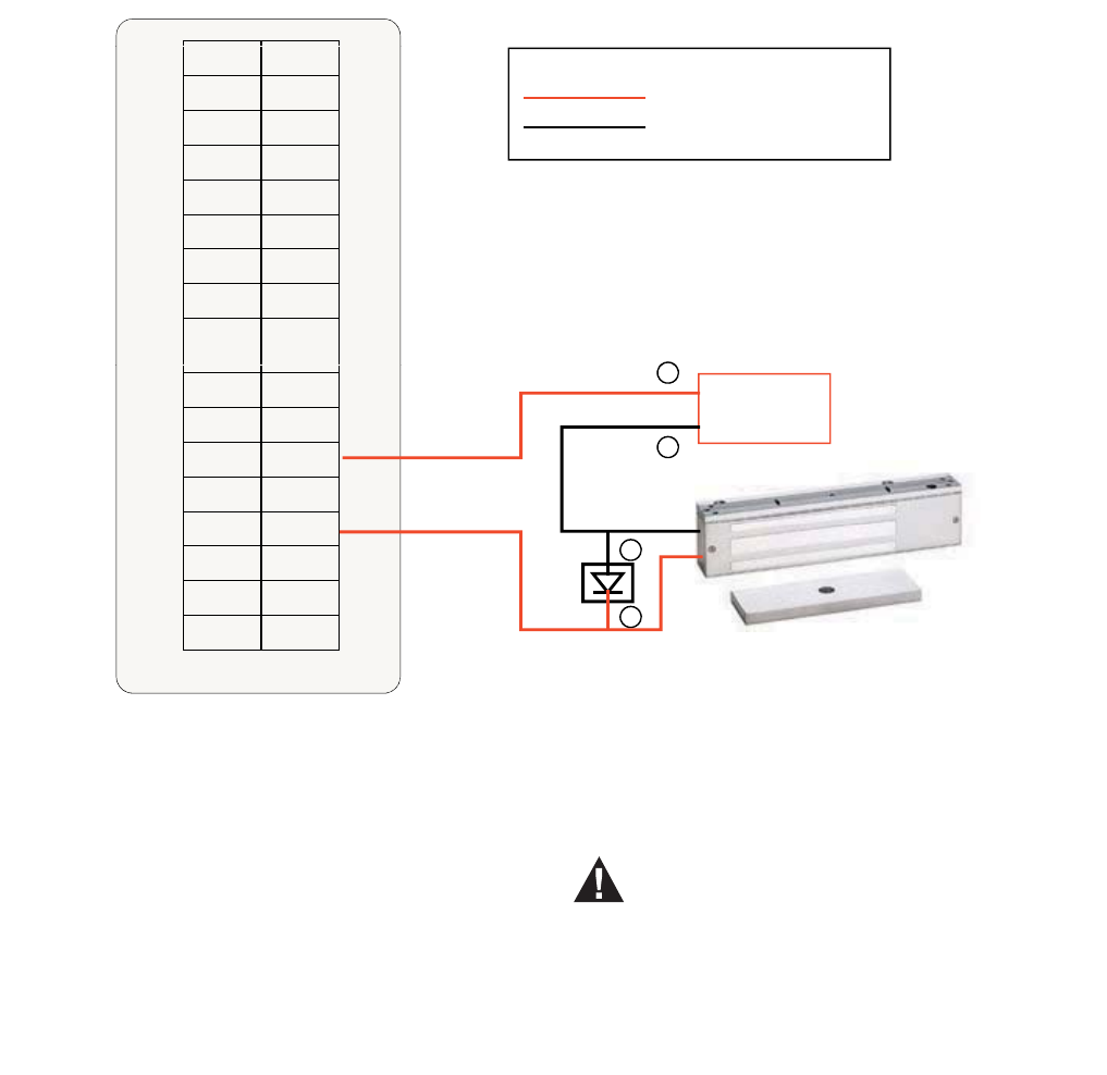
HONEYWELL IDENTIPOINT™ INTELLIGENT SMARTCARD SYSTEM
35 95-7767
Magnetic lock connected to the IOM:
Fig. 28. Connections between IOM and magnetic lock
1. Connect 12VDC+ of the power supply to either the NC
or Common pin of Relay 0 or 1 (J12 or J13) of the IOM,
and the 12VDC- to the -ve pin of the magnetic lock.
2. In the same port (J12 or J13), connect the NC or Com-
mon, whichever is left free to the +ve pin of the magnetic
lock.
In this setup, the door will remain locked as long as power is
provided and will unlock in the absence of power. If the reader
is powered off in this situation, the door will unlock.
NOTE: The above describes one way of wiring the mag-
netic lock. Wiring must be done strictly as per the
stipulated safety codes that the building must
follow. Accordingly, the wiring would be either
done in a fail-safe or fail-secure configuration.
For description of IOM pins refer to Table.8.
Supervisory Analog Input (SAI)
termination circuit
WARNING
Exit switch wiring must be completed within the
protected area or not readily accessible outside
the protected area.
A typical termination circuit for SAI is shown in Fig.29:
1. Connect a 1 K resistor (0.5W axial type, 5% toler-
ance) in series with SAI-n and the sensor switch.
2. Connect a 2 K resistor (0.5W axial type, 5% toler-
ance) in parallel with the input pins and the sensor
switch.
Such a termination circuit can be connected to the SAI of an
IdentIPoint reader as well as the IOM. This loop can detect
tampering by shorting across or cutting the loop. Four states
can be detected by the IdentIPoint device: open, short, cut
and closed.
Power – Min. 18 AWG
Power Gnd – Min. 18 AWG
LEGEND
GNDSAI-0
DO-1GND
GNDDI-1
DO-0GND
GNDDI-0
485-
GND
SAI-2
ILK-1GND
GNDSAI-1
ILK-0GND
RLO
C
GND
N.OSAO
N.CGND
485-ASAI-3
485-BGND DC – Power
12VDC/24VDC
_
+
RL1-C
N.OGND
N.C12V
RLO
-
C
GND
IO module
Magnetic Lock
FGND
1457020-001
Diode Suppression
+
_
RED
BLK
Network
:
:
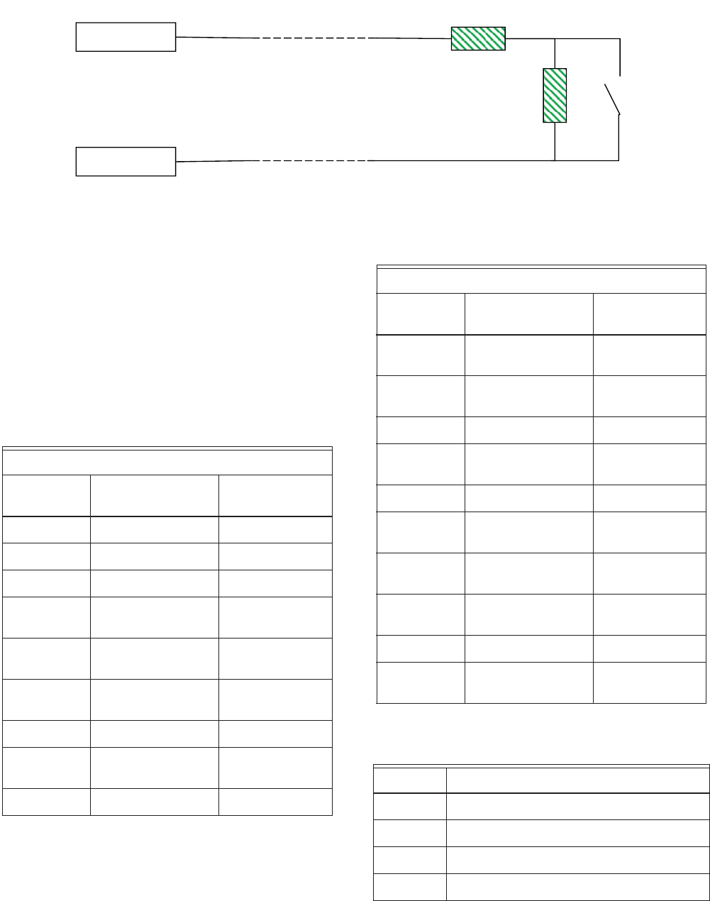
HONEYWELL IDENTIPOINT™ INTELLIGENT SMARTCARD SYSTEM
95-7767 36
Fig. 29. Connections for Supervisory Analog Inputs
NOTE: REX and Door Sense support only Normally
Closed and not Normally Open positions, i.e.,
REX is detected when SAI switch is open, Door is
sensed as open when SAI switch is open.
CONNECTOR AND SWITCH
DESCRIPTIONS
For Readers:
Table 5. Reader J9 connector signals
Table 6. Reader J10 connector signals
Table 7. Reader S1 DIP Switch settings
SAI-n
1K Ω
2
Sensor
SAI-n GND
KΩ
Switch
Connector: J9
Pin
Number Signal Connector Wire
1 Power-IN RED
2 Power-GND BLACK
3 Relay-Common ORANGE
4 Relay-Normal
Close
WHITE/
ORANGE
5 Relay-Normal
Open
WHITE
6 Supervisory Analog
Input (SAI) 0
GREEN
7 SAI 0 GND WHITE/GREEN
8 Supervisory Analog
Input (SAI) 1
BLUE
9 SAI 1 GND WHITE/BLUE
Connector: J10
Pin
Number Signal Connector Wire
1 Power Output for
Door Strike
RED
2 Ground for Door
Strike
BLACK
3 RS485-A YELLOW
4 RS485-B WHITE/
YELLOW
5 RS485-GND GREY
6 Digital Output
(Current Sink)
ORANGE
7 Digital Output GND WHITE/
ORANGE
8 Supervisory Analog
Input (SAI) 2
VIOLET
9 SAI2 GND WHITE/VIOLET
10 Frame GND (ESD
GND)
WHITE/BLACK
Position Effect when "ON" (position left)
1 RS485-A pull up
2 RS485 termination
3 RS485-B pull down
4 Wi-fi Disable

HONEYWELL IDENTIPOINT™ INTELLIGENT SMARTCARD SYSTEM
37 95-7767
For IOM:
Table 8. IOM Connector Signals
Connector Signal Description
Connector: J1
1 12V DC Power 12VDC Power Input, tolerate up to 28VDC
2 Power Ground Power Ground
Connector J2
1 SAO Supervisory Analog Output, repeats the input of SAI-3
2 SAO-GND Supervisory Analog Output Ground
Connector J3
1 F-GND Frame Ground (note 1)
2 F-GND Frame Ground
Connector J4
1 DIN-0 Digital Input 0 (note 2)
2 DIN-0-GND Digital Input 0 Ground
Connector J5
1 DIN-1 Digital Input 1 (note 2)
2 DIN-1-GND Digital Input 1 Ground
Connector J6
1 SAI-0 Supervisory Analog Input 0
2 SAI-0-GND SAI 0 Ground
Connector J7
1 SAI-1 Supervisory Analog Input 1
2 SAI-1-GND SAI 1 Ground
Connector J8
1 SAI-2 Supervisory Analog Input 2
2 SAI-2-GND SAI 2 Ground
Connector J9
1 SAI-3 Supervisory Analog Input 3
2 SAI-3-GND SAI 3 Ground
Connector J10
1 DO-0 Digital Output 0, current sinking output
2 DO-0-GND Digital Output 0 Ground
Connector J11
1 DO-1 Digital Output 1, current sinking output

HONEYWELL IDENTIPOINT™ INTELLIGENT SMARTCARD SYSTEM
95-7767 38
NOTE:
1. Frame-Ground should always be the first signal to connect to and last signal to disconnect from the system.
2. Pulled-up to high level internally.
2 DO-1-GND Digital Output 1 Ground
Connector J12
1 RL-0-Com Relay 0 Dry Contact Common
2 RL-0-NO Relay 0 Dry Contact Normal Open
3 RL-0-NC Relay 0 Dry Contact Normal Close
Connector J13
1 RL-1-Com Relay 1 Dry Contact Common
2 RL-1-NO Relay 1 Dry Contact Normal Open
3 RL-1-NC Relay 1 Dry Contact Normal Close
Connector J14
1 RS485-A RS485 bus A (non-inverting signal) signal
2 RS485-B RS485 bus B (inverting signal) signal
3 RS485-GND RS485 bus Ground
Connector J17
1 InterLock-0 Interlock Input 0 (Relay 0 bypass activation)
2 InterLock-0-GND Interlock 0 Ground
Connector J18
1 InterLock-1 Interlock Input 1 (Relay 1 bypass activation)
2 InterLock-1-GND Interlock 1 Ground
1 12V DC Power 12VDC Power Input, tolerate up to 28VDC
Connector Signal Description

HONEYWELL IDENTIPOINT™ INTELLIGENT SMARTCARD SYSTEM
39 95-7767
Table 9. IOM Switch Functions
Table 10. IOM S1 DIP switch settings
Table 11. IOM S3 DIP switch settings
RS485 Communication and
Termination Setting
CAUTION
If the Bus wiring enters or exits the building, the
protectors listed in Table.13 must be used. Bus
length for RS485 must not exceed 500 m end-to-
end.
RS485 is a 2-wire balanced multi-drop serial bus, which
allows a master unit to send and receive data to and from its
slave units. When an IdentIPoint reader is connected to one or
more IOMs, the reader is the master unit while the IOMs are
the slave units. Each unit, having its own RS485 address, is
connected in parallel to the RS485 bus. The length of the bus
must not exceed 1640 ft (500 m), end-to-end. The master
always assumes address zero. The master facilitates the
communication of data between itself and a particular slave
unit in a particular instance. For IOM address setup, see
section IOM Address Set up of Connector and Switch
Descriptions topic.
The RS485 serial signal travels down the stream, usually over
unshielded twisted pair cables. A suitable termination resistor
has to be put at the end of the RS485 line to absorb the
remaining energy on the line to prevent signal reflection. A
100 ohm resistor is chosen as it stays closest to the
characteristic impedance of the transmission line.
IdentIPoint readers and IOMs are both equipped with a
termination circuit and do not need an external termination
resistor. Setting bit 2 on S1 DIP switch to ON introduces a
termination resistor on the RS485 line. The units that sit
physically on both ends of an RS485 bus should have their
RS485 termination turned on. To minimize error signals
induced on the RS485 bus during its high-impedance state, it
is also recommended to turn on the pull-up and pull-down
resistors in the IdentIPoint reader (master) as shown in Fig.
30. See Table.7 and Table.10 for S1 DIP switch settings for
readers and IOM.
Switch Description
S1 RS485 Termination Control DIP
switch
S2 Initialization Button
S3 IOM Address set up DIP switch
S4 Cover tamper detection switch
Position Description
1 RS485-A pull up
2 RS485 Termination
3 RS485-B pull down
4Reserved
Position Description
1 Address value 1
2 Address value 2
3 Address value 4
4 Address value 8
5 Address value 16
6 Address value 32
7 Address value 64
8 For IOM setup, normally set to OFF
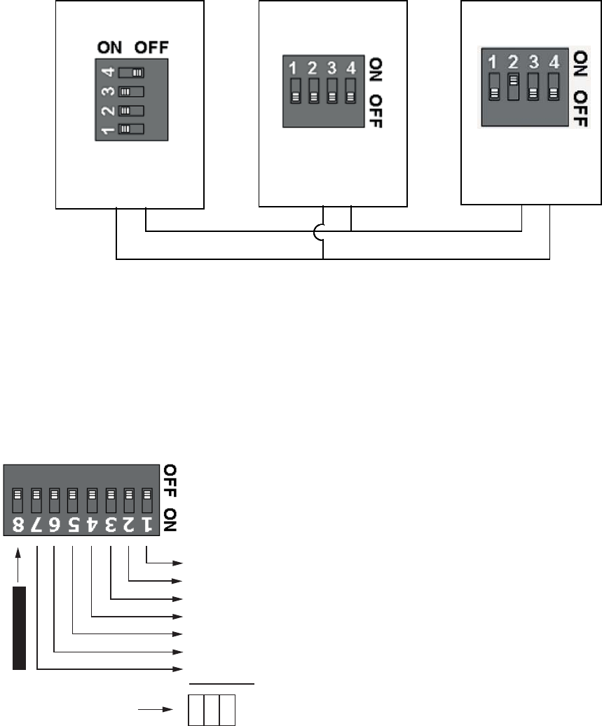
HONEYWELL IDENTIPOINT™ INTELLIGENT SMARTCARD SYSTEM
95-7767 40
Fig. 30. S1 DIP Switch settings on reader and IOMs for RS485 termination
IOM Address Set up
Each IOM should have its own address. S3 DIP switch on the
IOM holds the RS485 address of each unit. The addresses
can range from 1 to 127, with position 1 corresponding to
20=1, position 2 to 21=2 and so on as shown in Fig.31. Never
use zero as IOM address as zero is reserved for the master
device.
Fig. 31. IOM Address set up
To work out the address, select a combination of bit locations
on the DIP switch. Each bit has its own value representation.
The RS485 address is obtained by adding all ON-bit values.
E.g. Decimal value 37 will be obtained by turning ON bits 1, 3
and 6 which is equivalent to 1+4+32.
NOTE: It is recommended not to attach more than 4 IOM
units to the RS485 bus to maintain a reasonable
signal/response time delay between the reader
and the IOMs. Hence IOM addresses must be
from 1 to 4 only. See Fig.32 for S3 DIP switch set-
tings for up to 4 IOMs.
Termination OFFTermination ON Termination ON
IOM (Slave 1)
Termination OFF
Reader (Master)
Termination ON
Pull-up ON
Pull-down ON
IOM (Slave 2)
Termination ON
Termination OFFTermination ON Termination ON
IOM (Slave 1)
Termination OFF
Reader (Master)
Termination ON
Pull-up ON
Pull-down ON
IOM (Slave 2)
Termination ON
Termination OFFTermination ON Termination ON
IOM (Slave 1)
Termination OFF
Reader (Master)
Termination ON
Pull-up ON
Pull-down ON
IOM (Slave 2)
Termination ON
Termination OFFTermination ON Termination ON
IOM (Slave 1)
Termination OFF
Reader (Master)
Termination ON
Pull-up ON
Pull-down ON
IOM (Slave 2)
Termination ON
+ 1
+ 2
+ 4
+ 8
+ 6
+ 2
+ 4
ALWAYS OFF
1
3
6
SUM all ON bit values
Never use address zero
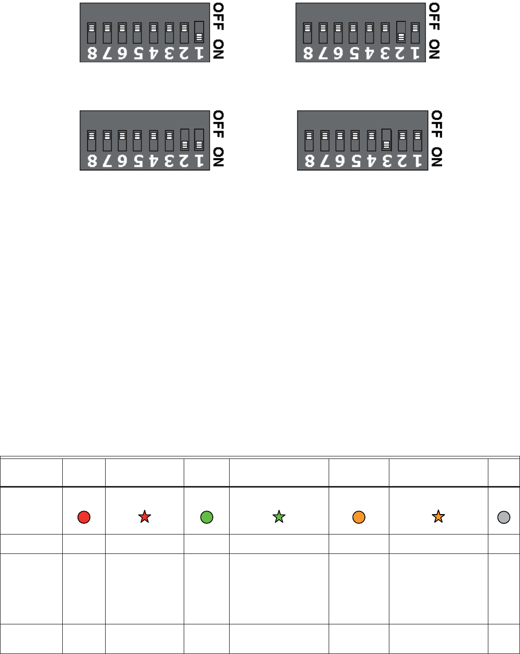
HONEYWELL IDENTIPOINT™ INTELLIGENT SMARTCARD SYSTEM
41 95-7767
Fig. 32. IOM Address set up - S3 Settings
CONFIGURING THE
HARDWARE
The LEDs at the back of the reader glow as follows when
power is applied to the device:
• Power - LED glows blue if power is applied to the reader.
• Activity - LED flashes amber when Ethernet cable is
connected and Ethernet is in communication; just remains
lit in other conditions.
• 10/100 - LED glows green when it is in 100M Ethernet
mode; remains unlit in all other conditions.
The LEDs on the front of the IOM glow as follows when power
is applied to the device:
Table 12. IOM LED States and Descriptions
IOM Address = 1 IOM Address = 2
IOM Address = 4IOM Address = 3
Color
RED BLINKING RED GREEN BLINKING GREEN AMBER * BLINKING AMBER * OFF
LED
Power _ _ _ On main power _ _ Off
Data No
Comm.
Comm. exists
but invalid data.
Blinks when
there is
incoming invalid
data
All well Comm. exists with
valid incoming data.
Blinks when there is
incoming or outgoing
data
Installation
state
Installation state.
Blinks when there is
incoming or outgoing
data
_
Tamper _ Unit tampered _ _ _ _ Unit
OK
o
p
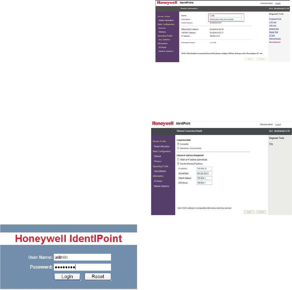
HONEYWELL IDENTIPOINT™ INTELLIGENT SMARTCARD SYSTEM
95-7767 42
* As the difference between the Red and Amber colors of the
LED is not significant, the user is advised to observe the
change of color from Red to Amber (or vice versa) by
comparing the LED with any other Red LED on the IOM.
IdentIPoint devices can be configured either over Ethernet or
Wi-fi.
Ethernet:
• Only works if plugged into a DHCP enabled network
• IP address will be shown on LCD screen
• If no LCD screen, or some distance to the reader, then use
the IdentIPoint Sync Application to discover the reader
Wi-fi:
• Need to create an ad-hoc network with the IdentIPoint
reader
• IP address of IdentIPoint is 192.168.0.200
NOTE:
• You need to have the Ethernet and wireless networks
on two different subnets and not on the same subnet
and you need to have matching routes in case a
machine is going to connect via both networks.
• Wifi network configuration is not a UL294 listed
configuration and should not be used on UL294
applications.
Logging In
1. Enable wireless by presenting any smart card.
2. Create an ad-hoc network with IdentIPoint.
— SSID is iPAC10.
3. Call up the web interface.
— http://192.168.0.200.
NOTE: This mode of connecting with the reader will no
longer be available after the reader has been dis-
covered and configured by EBI. To regain this
capability, the reader's factory reset switch must
be activated. The reader can then be reconfig-
ured.
4. Log in to the webpage using the dialog box as shown
— User: "admin".
— Password: "password".
— These should be changed later.
Reader Name
1. Enter a name for the reader
— This will become the Point Name in EBI.
2. Enter a description for the reader.
Hints:
— Name the reader uniquely.
— Use the reader description to reflect location.
Connection
1. Choose Ethernet parameters.
2. If using wireless, ensure data entered is 100% correct.
— Perform a "factory reset" if anything goes wrong.
Hint:
— Assign a well known Ethernet IP for a wireless or
stand-alone reader.
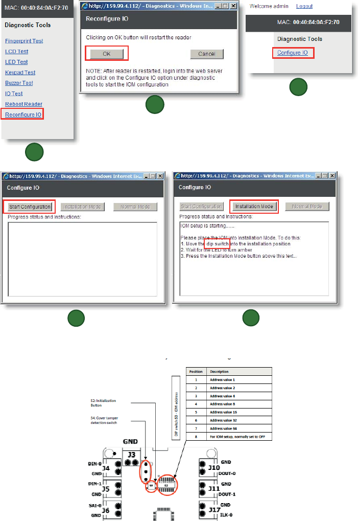
HONEYWELL IDENTIPOINT™ INTELLIGENT SMARTCARD SYSTEM
43 95-7767
I/O
Out-of-the-box assumes that there is no IO Module.
1. If an IO Module is used, simply click the link and follow the prompts as shown in figures labeled 1 through 5.
2. Position 8 of this switch is the IOM setup "dip switch.
1
2
3
4
5
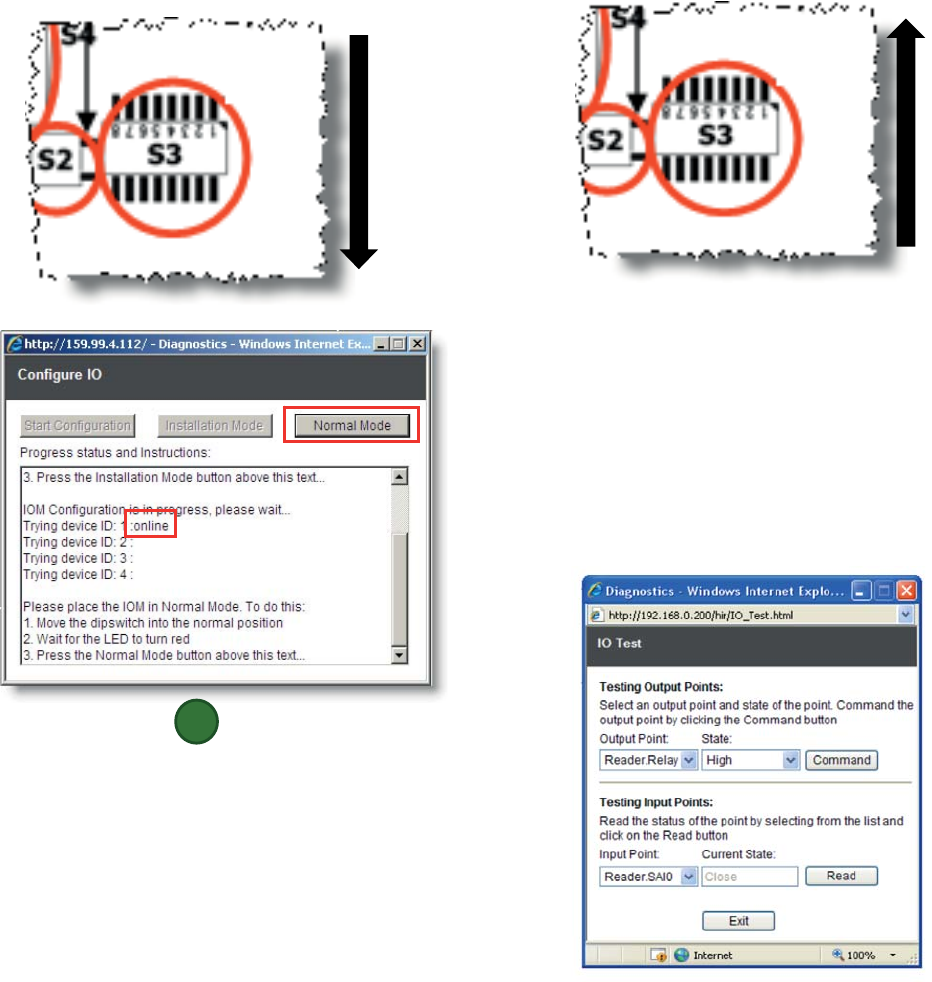
HONEYWELL IDENTIPOINT™ INTELLIGENT SMARTCARD SYSTEM
95-7767 44
3. Slide it down as shown to turn it ON.
4. Slide switch up to put in normal position.
Door
1. Select the door IO addresses.
2. Enter door timings.
3. Enter door behavior.
Hint
— If common wiring & behavior it is quicker to do this
from EBI later.
Testing the Door I/O
1. Select the Output Point and the desired level.
2. Select the Input Point to see its current value.
6
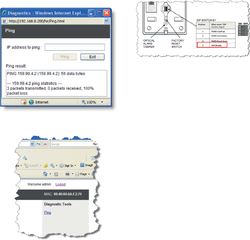
HONEYWELL IDENTIPOINT™ INTELLIGENT SMARTCARD SYSTEM
45 95-7767
Testing the Network
1. Ping a well known IP Address.
Finishing
1. Logout of the webpage.
2. Present the card to the reader to disable wireless
3. If wireless will never again be used on this reader, it can
be disabled in the hardware by setting bit 4 in the S1
DIP switch to ON (position left).
MAINTAINING THE
IDENTIPOINT READERS
System health tests
All system health tests described in this section can be
performed from the IdentIPoint device web pages. See
Configuring the Hardware topic for details on accessing the
same.
To perform fingerprint test:
1. Click Reader Information under Reader Profile. The
reader information page is displayed.
2. Click Fingerprint Test from the Diagnostics and Tools
list. The Finger Print Module Test page is displayed.
3. Click Test. A message Provide Your Finger Print
appears on the LCD of the reader.
4. Present your fingerprint on the scanner. The reader
scans the finger impression. A message Processing
Completed appears on the LCD indicating the comple-
tion of the scanning process. While holding or swiping
the finger should cover the IR sensor near to FP module
other wise the reader functionality will not work.
5. A message Provide Your Finger Print Again appears on
the LCD of the reader. Present your fingerprint on the
scanner. The reader scans the finger impression. A
message Processing Completed appears on the LCD
indicating the completion of the scanning process.
6. If the fingerprint matches then a message Finger Print
Matches appears on the reader LCD else a message
Finger Print Mismatches appears.
To perform LCD test:
1. Click LCD Test from the Diagnostics and Tools list. The
LCD Test page is displayed.
2. Type the message you want to convey in the Type Mes-
sage here box.
3. Click Test. The typed text is displayed on the LCD of the
reader.
4. Click Exit, to close the page.
To perform LED test
1. Click LED Test from the Diagnostics and Tools list. The
LED Test page is displayed.
2. Click the appropriate option from the Observe the LED
glowing.

HONEYWELL IDENTIPOINT™ INTELLIGENT SMARTCARD SYSTEM
95-7767 46
3. Click Test. The selected color blinks on the LED.
4. Click Exit. Exit from the LED test window.
To perform keypad test:
1. Click Keypad Test from the Diagnostics and Tools list.
The Keypad Test window is displayed.
2. Click Test to initiate the test.
3. Type any 'num' keys on the keypad. The same text is
displayed on the LCD of the reader.
4. Click Exit to close the page.
To perform IO test:
1. Click IO Test from the Diagnostics and Tools list, the
IO Test page is displayed.
2. For testing the output points select an output point from
the Output Point drop-down list.
a. Select a state from the State drop-down list.
b. Click Command, to set the command. The device
connected to the respective output point is set to the
appropriate selected state.
3. For testing the input points select an input point from the
Input Point dropdown list.
a. Click Read, to read the input channel status.
b. The state of the device that is connected to the input
point is displayed in the Current State text box.
To reboot the reader:
1. Click Reboot Reader from the Diagnostics and Tools
list. The Reboot Reader page is displayed.
2. Click Reboot, reboots the card reader.
To check the IP:
NOTE: The availability of an IP address is checked on
Ethernet and Wireless page.
1. Click Ping from the Diagnostics and Tools list on Ether-
net or Wireless page. The Ping page is displayed.
2. Type the IP to be searched in IP address to ping text
box.
3. Click Ping. The result is displayed on the Ping result
window.
To perform a factory reset on the reader:
1. Keeping the reader powered on normally, remove it from
the back-plate and find the factory reset switch at its
back (see Fig.3).
2. Press the factory reset switch for 10 seconds or more
until the reader LED/LCD is turned off.
3. When the LED/LCD is off, release the factory reset
switch.
4. Wait for the reader to restart.
5. If using an LCD model, the Honeywell banner will
appear on the display for a few seconds and then disap-
pear.
6. Within 1 minute, the reader LED will start flashing green
indicating that the reader has been reset to the factory
firmware.
7. If using an LCD model with a DHCP server connected
via Ethernet, the following will appear on the display
within 1 minute:
Honeywell
IdentIPoint
Version: 1.0.18.0
aaa.bbb.ccc.ddd (where "aaa.bbb.ccc.ddd" is the IP
address assigned by DHCP)
8. If using an LCD model WITHOUT a DHCP server con-
nected via Ethernet, the following will appear on the
display within 3 minutes:
Honeywell
IdentIPoint
Version: 1.0.18.0
<blank> (no IP address assigned)
NOTE: In case factory reset fails (which might happen if
the factory reset switch is not released in time at
step 3), the reader will beep multiple times while
it is restarting. Afterwards it will not respond
when a card is presented.
To recover from factory reset failure:
1. Power off the reader and power it on again.
2. Wait for the reader to start in normal mode.
3. Repeat all the required factory reset steps above.
LIGHTNING PROTECTION
Standard Lightning Protectors
If the Bus wiring enters or exits the building, the protector (s)
listed in Table.13 must be used. Bus length must not exceed
3277 ft. (999 m). Refer to Honeywell Form No.95-7266
14502412 Lightning Protector Installation Instructions, and
applicable local codes and standards for lightning protector
installation.
Table 13. Lightning and Surge Protectors
Part Number Description
14502412-011 120VAC Input Line
14502412-012 Low Voltage Input Line
14502412-014 Transmission Bus (RS485, F&S and
Security Bus) Secondary Protection
14502412-020 Transmission Bus (RS-232 Bus)
Secondary Protection
14507678-004 Ethernet Port Surge Protector

HONEYWELL IDENTIPOINT™ INTELLIGENT SMARTCARD SYSTEM
47 95-7767
CERTIFICATIONS
READERS
•CE
•C-tick
• IP-65 (Basic Outdoor Version Only)
United States
• FCC 47 CFR Part 15, Subpart B, sections 107(a) & 109(a)
Class B
• Section 201 to Section 205, section 207, section 209,
section 215c, section 247 and section 35c
European Union
• EN 55022:2006; EN61000-3-2:2006
• EN 61000-6-3:2007
• EN 50130-4:1995+A1:1998+A2:2003
• EN 60950-1:2001
• EN 301 489-01 V1.6.1
• EN 301 489-03 V1.4.1
• EN 300 330-02 V1.3.1
• EN 50133-1:1997
• EN 50133-2-1:2000
• EN 50134-1:2000
• EN 50134-3:2001
Canada
• Canadian ICES-003 Class B
IOM
•CE
•C-tick
United States
• FCC 47 CFR Part 15, Subpart B, sections 107(a) & 109(a)
Class B
• Section 201 to Section 202, section 207
European Union
• EN 55022:2006EN 60950-1:2001
Canada
• Canadian ICES-003 Class B
WARNING
Any changes or modifications not expressly
approved by the party responsible for compliance
could void the user's authority to operate the
equipment.
This device complies with part 15 of the FCC Rules. Operation
is subject to the following two conditions:
• This device may not cause harmful interference
• This device must accept any interference received,
including interference that may cause undesired operation.
FCC Radiation Exposure Statement:
This equipment complies with FCC radiation exposure limits
set forth for an uncontrolled environment .This equipment
should be installed and operated with minimum distance of 20
cm between the radiator& your body.

HONEYWELL IDENTIPOINT™ INTELLIGENT SMARTCARD SYSTEM
Automation and Control Solutions
Honeywell International Inc.
1985 Douglas Drive North
Golden Valley, MN 55422
www.honeywell.com/buildingsolutions
® U.S. Registered Trademark
© 2012 Honeywell International Inc.
95-7767 HSL. Rev. 05-12
Printed in U.S.A.
Notice
This document contains Honeywell proprietary information.
Information contained herein is to be used solely for the
purpose submitted, and no part of this document or its
contents shall be reproduced, published, or disclosed to a
third party without the express permission of Honeywell
International, Sarl.
While this information is presented in good faith and believed
to be accurate, Honeywell disclaims all implied warranties,
including, without limitation, the implied warranties of
merchantability and fitness for a purpose, and makes no
express warranties except as may be stated in its written
agreement with and for its customer.
In no event is Honeywell liable to anyone for any indirect,
incidental, special or consequential damages.
The information and specifications in this document are
subject to change without notice.
Copyright © 2012 Honeywell International Inc.
Honeywell Trademarks
IdentIPoint™ is a registered trademark of Honeywell
International Inc.
Other Trademarks
Microsoft and SQL Server are either registered trademarks or
trademarks of Microsoft Corporation in the United States and/
or other countries.
Trademarks that appear in this document are used only to the
benefit of the trademark owner, with no intention of trademark
infringement.
Support and other contacts
For technical assistance, call your nearest Honeywell office.
Feedback
Honeywell appreciates your comments about this manual.
Please visit us on the web at www.honeywell.com/
buildingsolutions to post your comments.