Honeywell BT010M 10 Meter BT Module User Manual Voyager 1200g 1202g User s Guide
Honeywell International Inc. 10 Meter BT Module Voyager 1200g 1202g User s Guide
UserManual.wiki
>
Honeywell
>
BT010M User Manual
>
User Manual
Contents
1.
User manual
2.
User Manual
User Manual
Navigation menu
Upload a User Manual
Namespaces
Wiki Guide
HTML
PDF
Info
Views
User Manual
Discussion / Help
Navigation
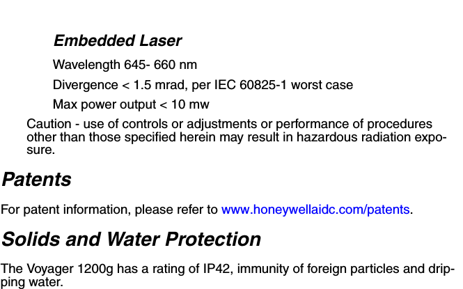
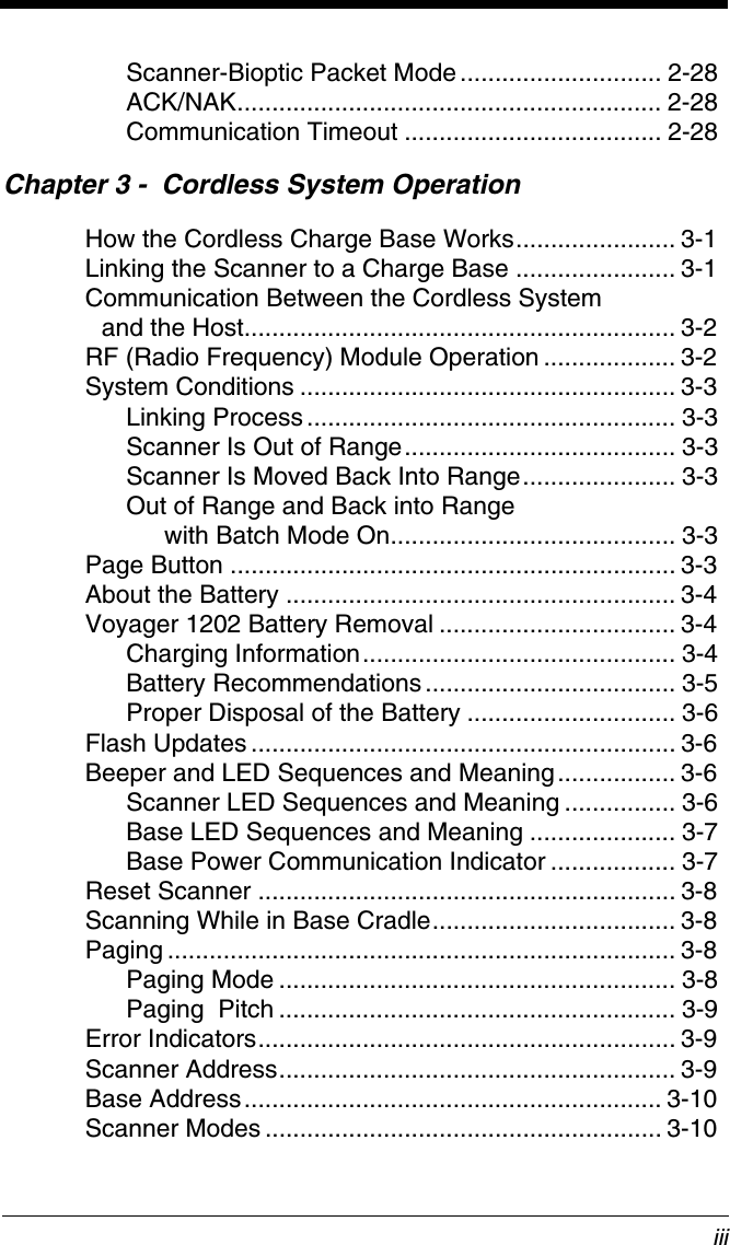
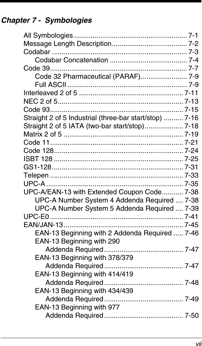
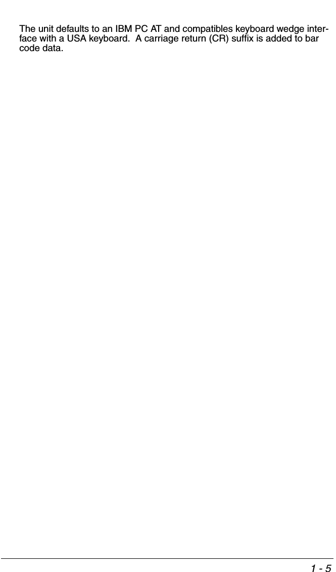
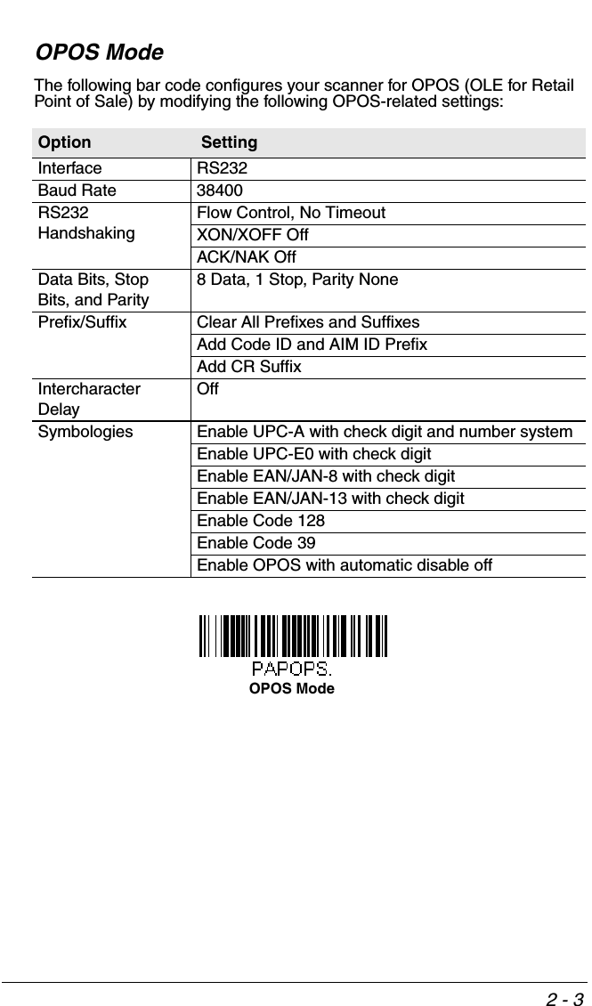
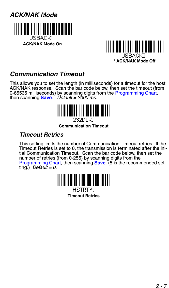
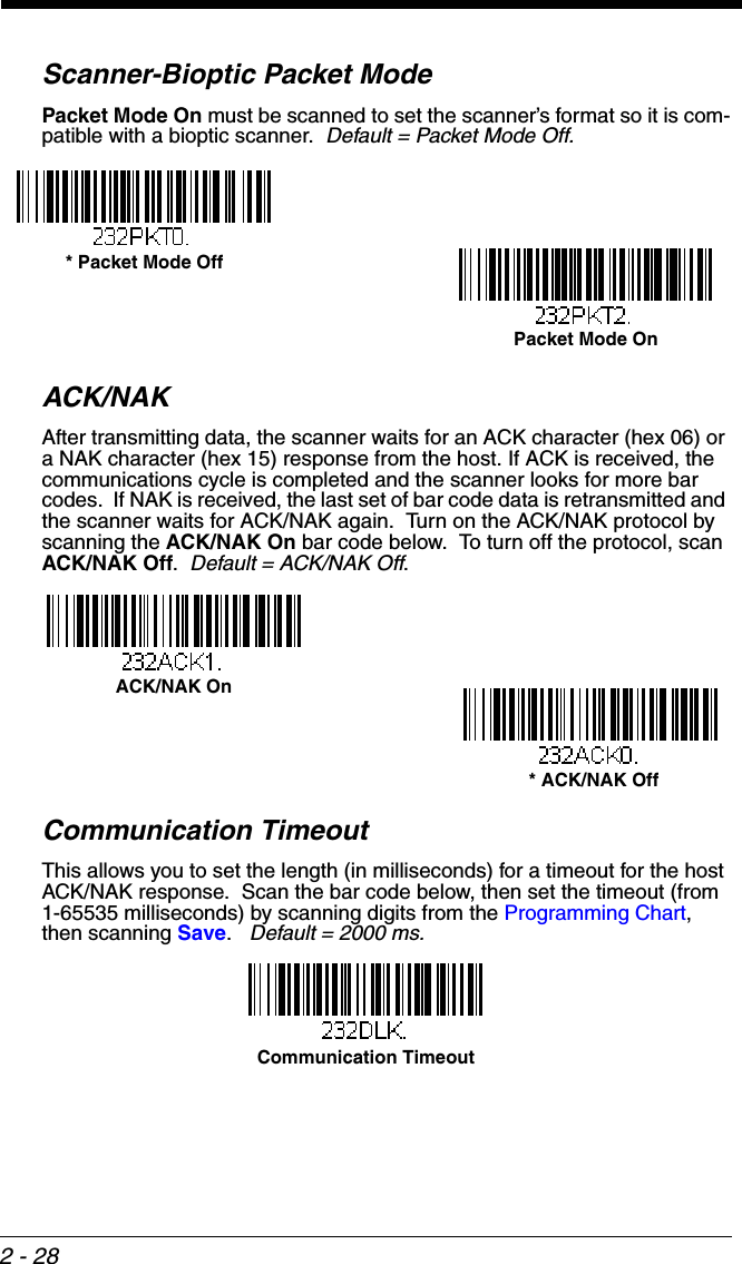
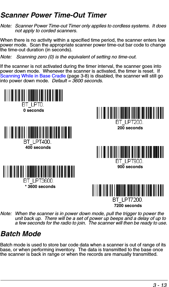
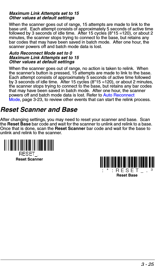
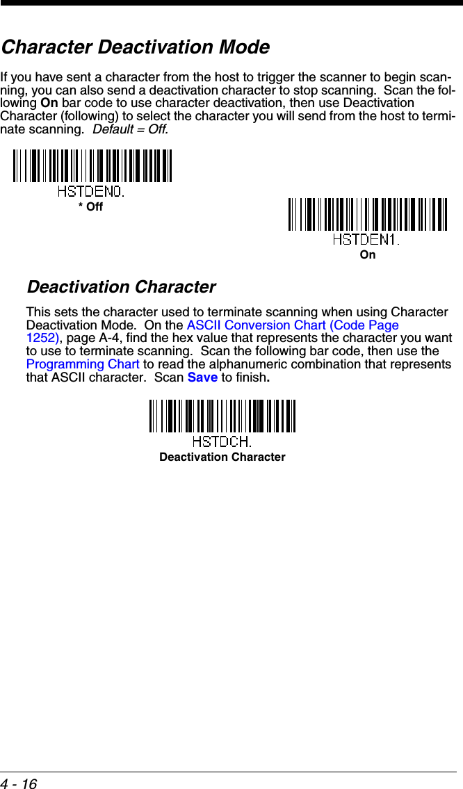
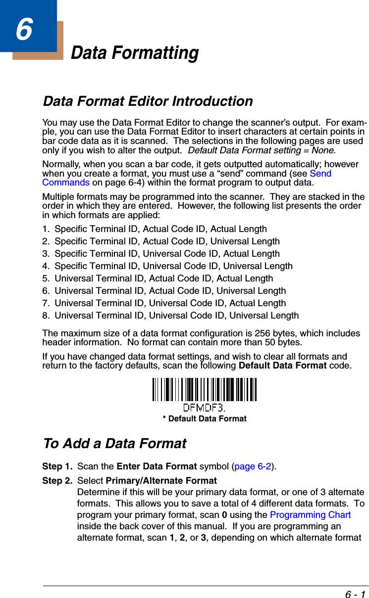
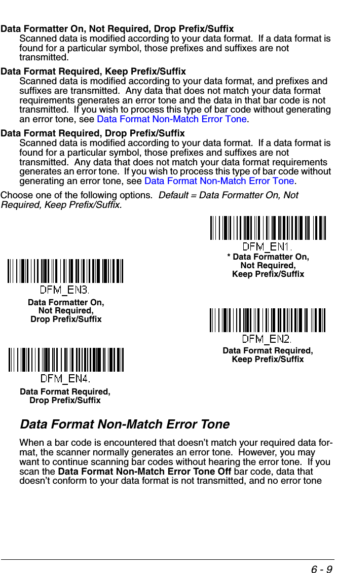
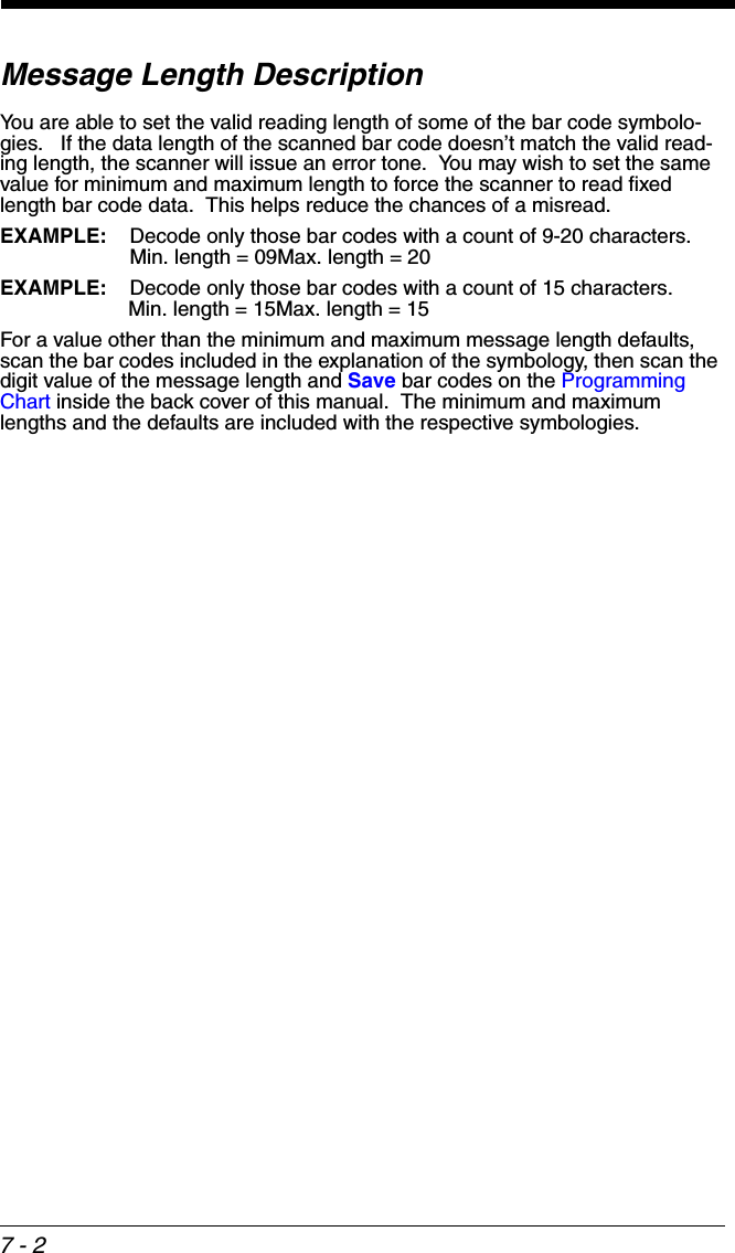
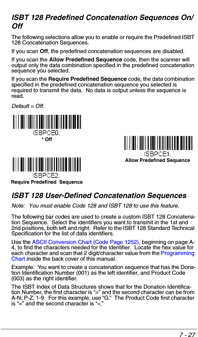
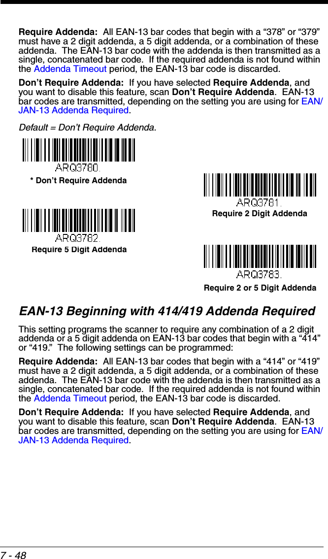
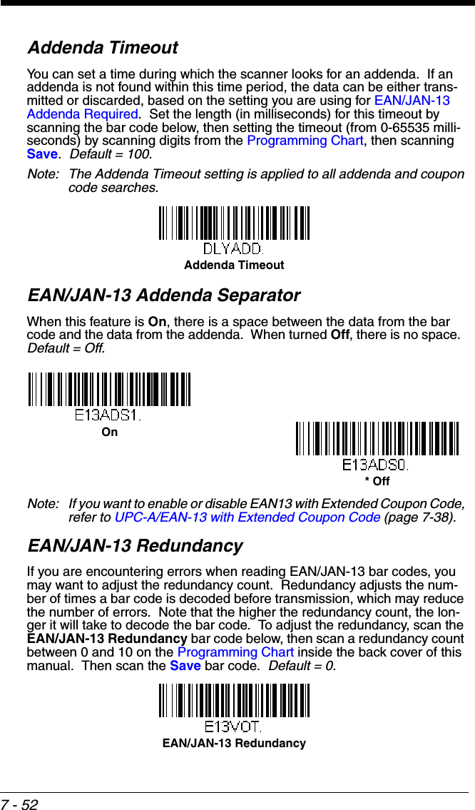
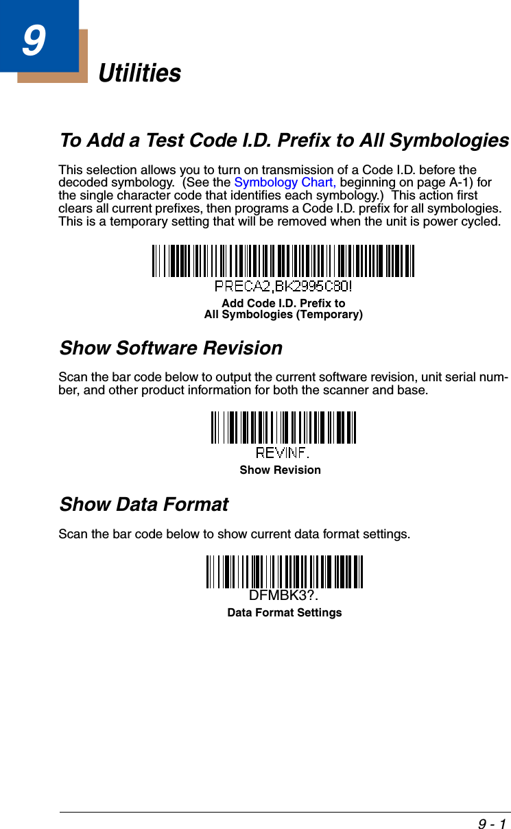
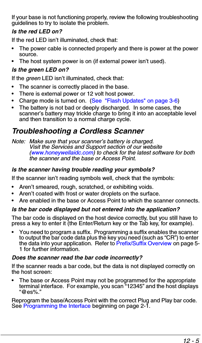
![2 - 13Keyboard Country LayoutScan the appropriate country code below to program the keyboard layout for your country or language. As a general rule, the following characters are sup-ported, but need special care for countries other than the United States:@ | $ # { } [ ] = / ‘ \ < > ~ * United States BelgiumFinlandGermanyFranceIBM FinancialHungaryArabicChineseItalyJapan ASCIIKorea](https://usermanual.wiki/Honeywell/BT010M.User-Manual/User-Guide-1663573-Page-49.png)
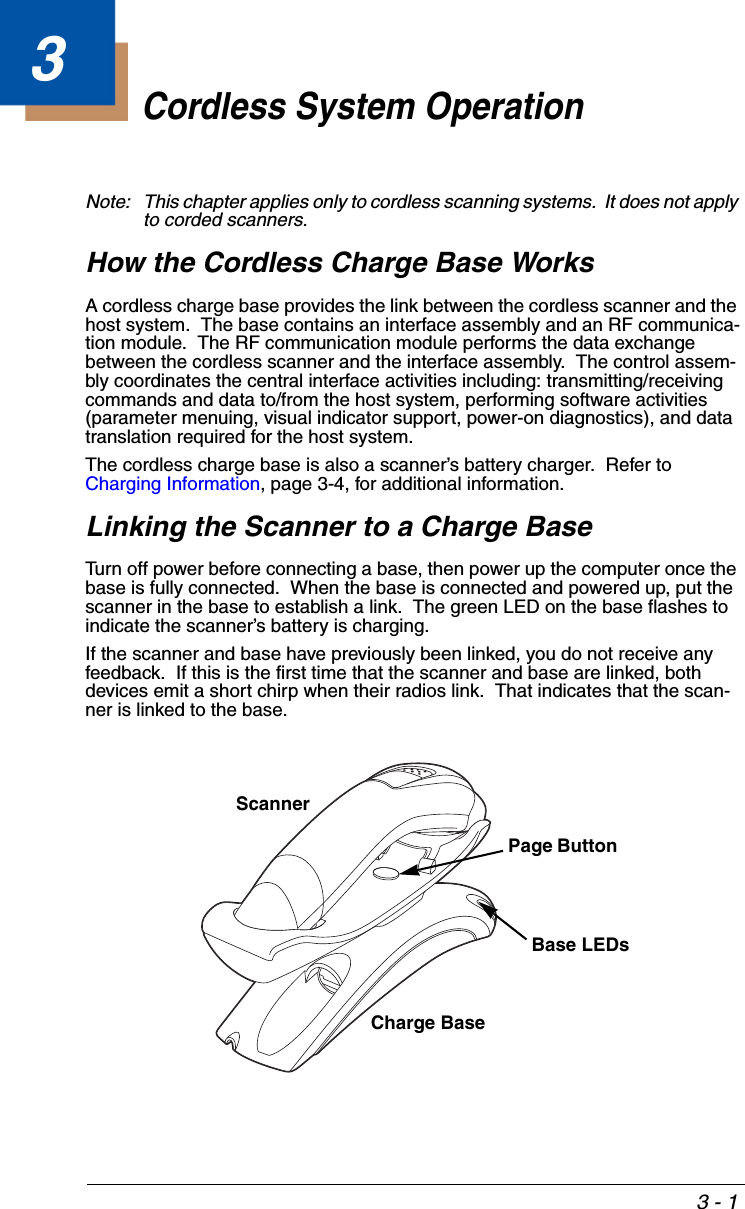


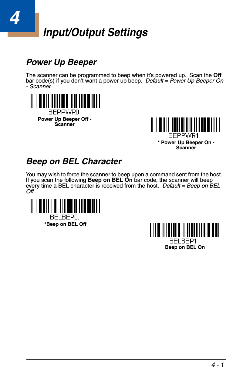
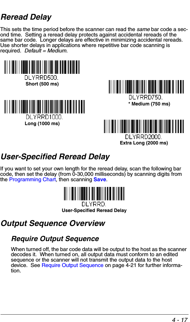

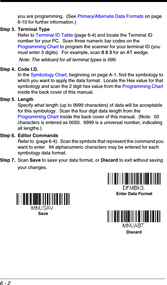
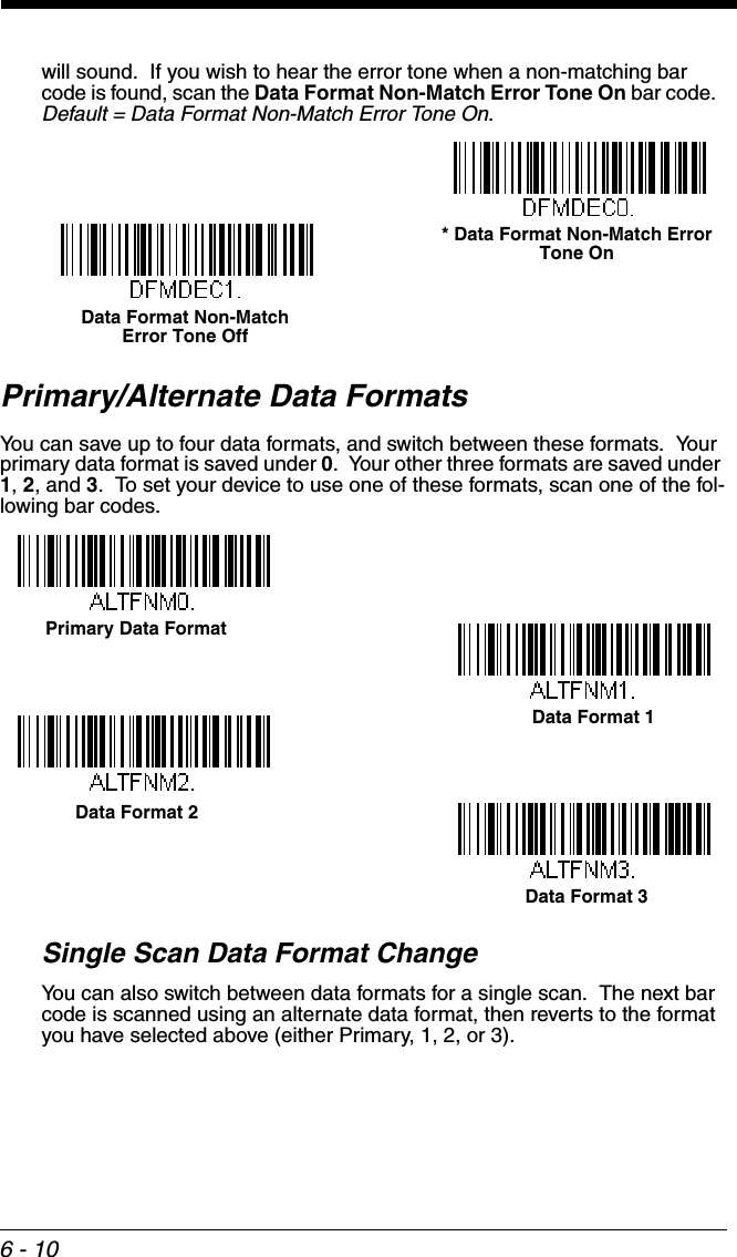

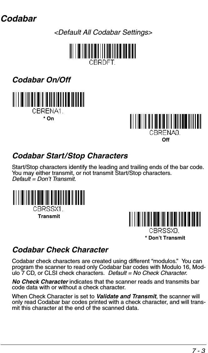
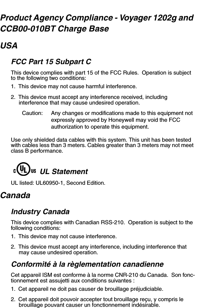
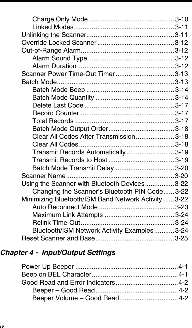
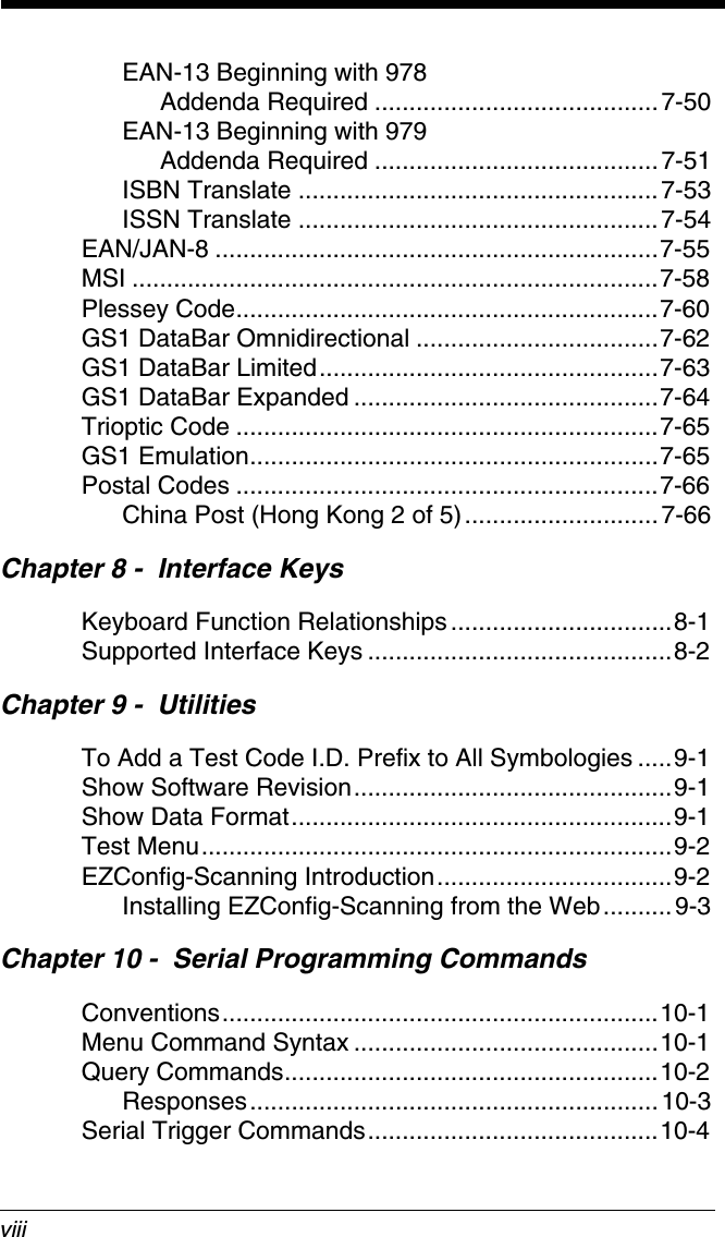
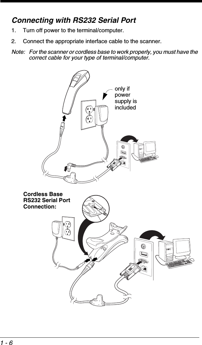
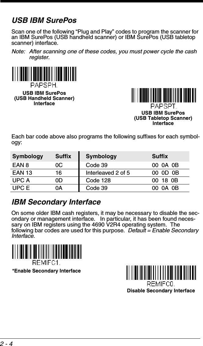
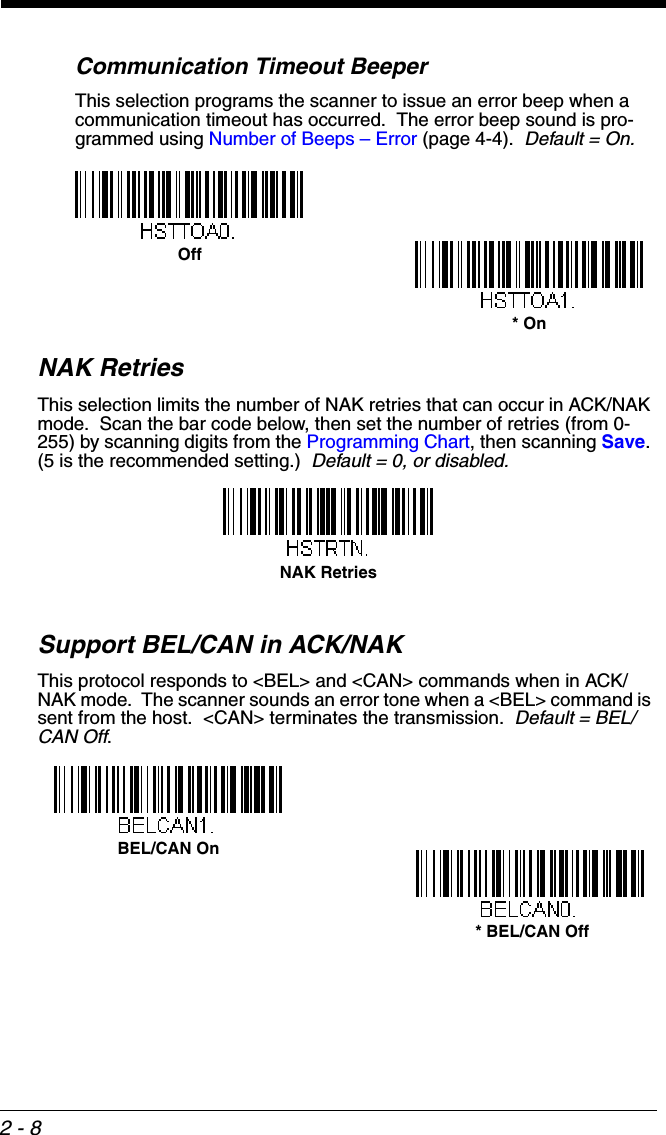
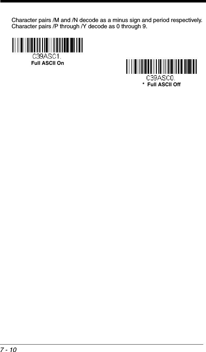
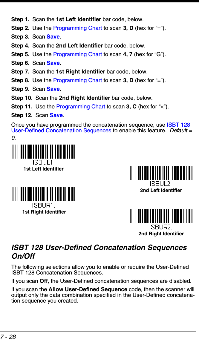
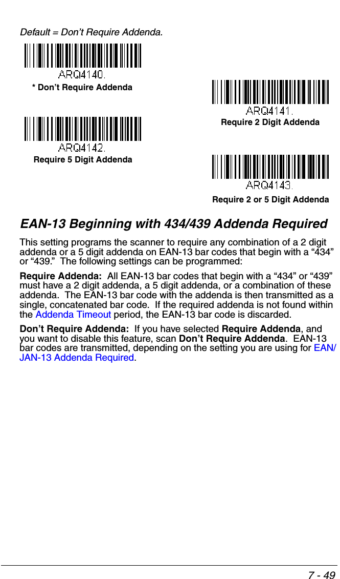
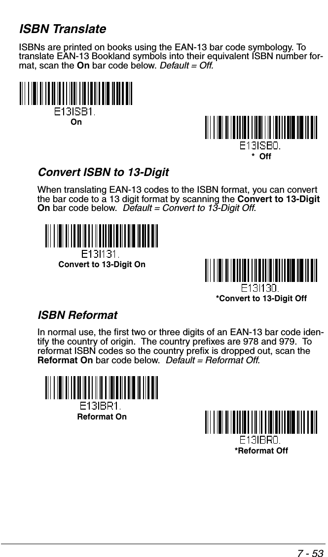
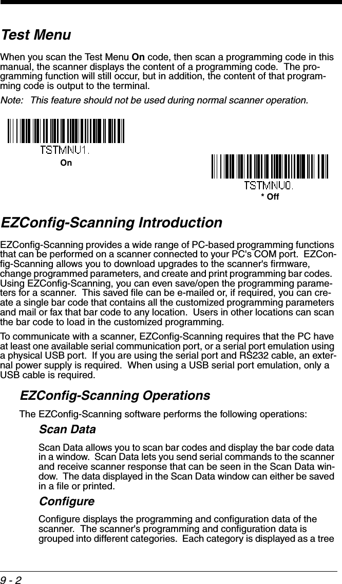
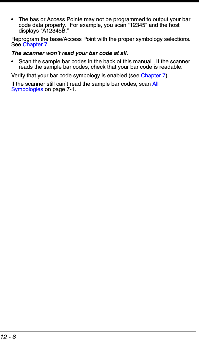
![7 - 9Code 32 Pharmaceutical (PARAF)Code 32 Pharmaceutical is a form of the Code 39 symbology used by Ital-ian pharmacies. This symbology is also known as PARAF.Full ASCIIIf Full ASCII Code 39 decoding is enabled, certain character pairs within the bar code symbol will be interpreted as a single character. For example: $V will be decoded as the ASCII character SYN, and /C will be decoded as the ASCII character #. Default = Off.NUL %U DLE $PSP SPACE00@%VPP‘%Wp+PSOH $A DC1 $Q !/A 11AAQQa+Aq+QSTX $B DC2 $R “/B 22BBRRb+Br+RETX $C DC3 $S #/C 33CCSSc+Cs+SEOT $D DC4 $T $/D 44DDTTd+Dt+TENQ $E NAK $U %/E 55EEUUe+Eu+UACK $F SYN $V &/F 66FFVVf+Fv+VBEL $G ETB $W ‘/G77GGWWg+Gw+WBS $H CAN $X (/H 88HHXXh+Hx+XHT $I EM $Y )/I 99IIYYi+Iy+YLF $J SUB $Z */J :/ZJJZZj+Jz+ZVT $K ESC %A +/K ;%FKK[%Kk+K{%PFF $L FS %B ,/L <%GLL\%Ll+L|%QCR $M GS %C -- =%HMM]%Mm+M}%RSO $N RS %D .. >%INN^%Nn+N~%SSI $O US %E //O ?%JOO_%Oo+ODEL %T* OffOn](https://usermanual.wiki/Honeywell/BT010M.User-Manual/User-Guide-1663573-Page-143.png)
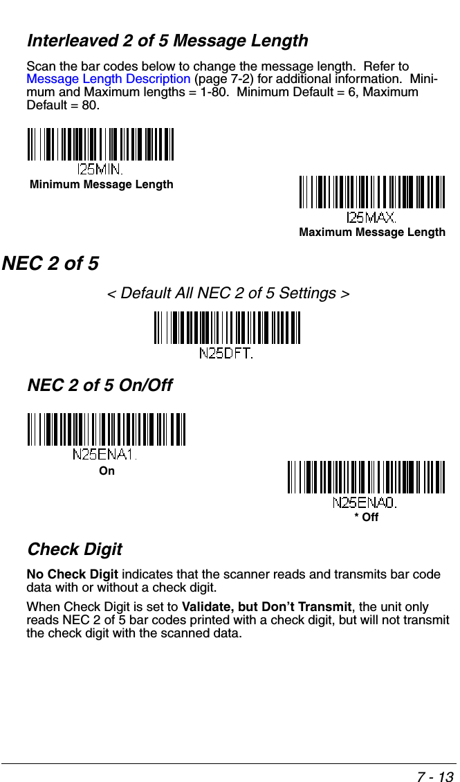
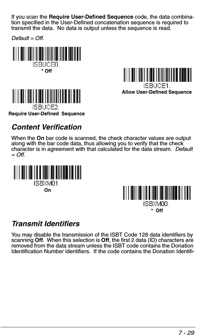

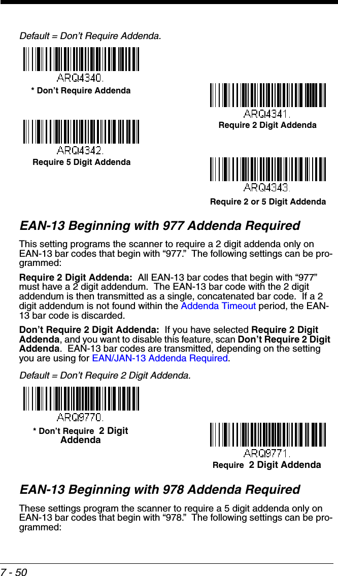
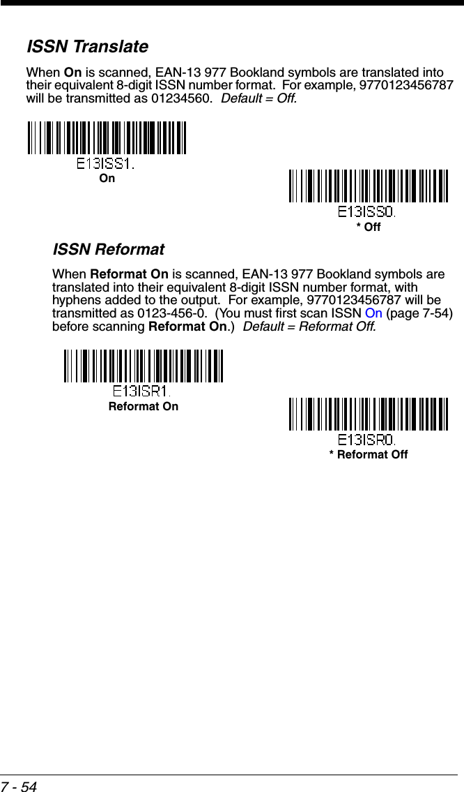
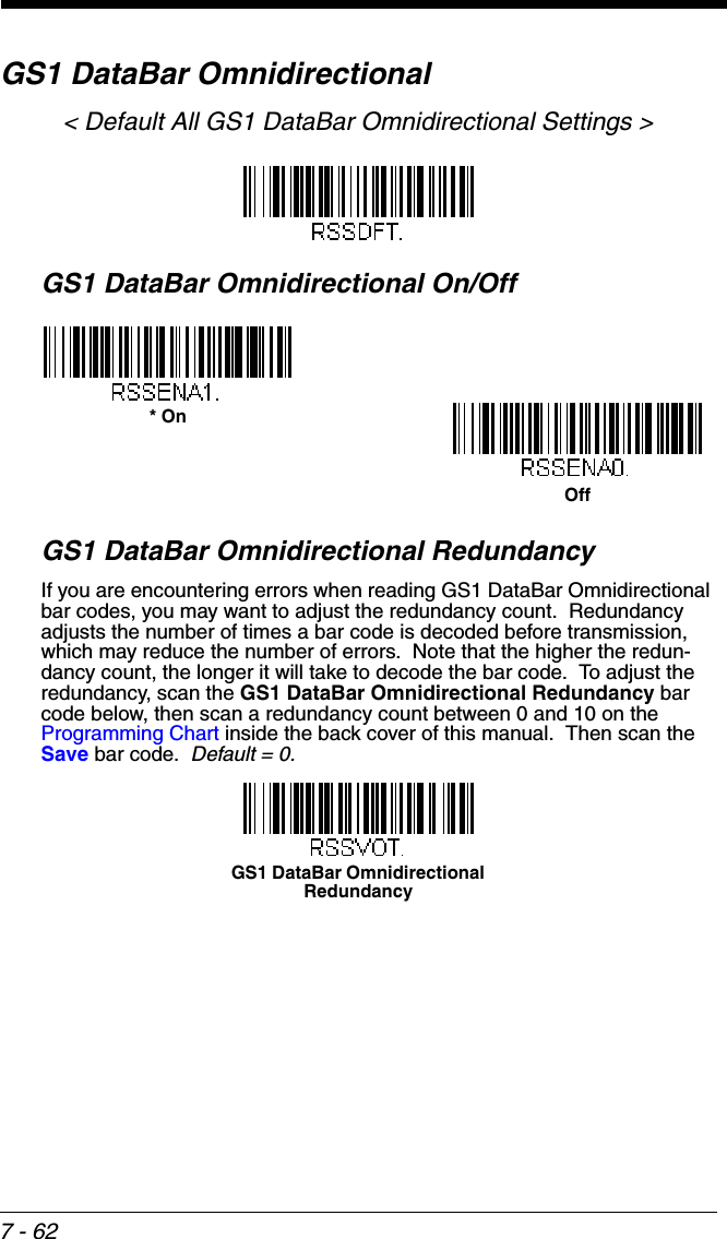
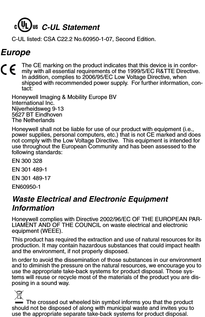
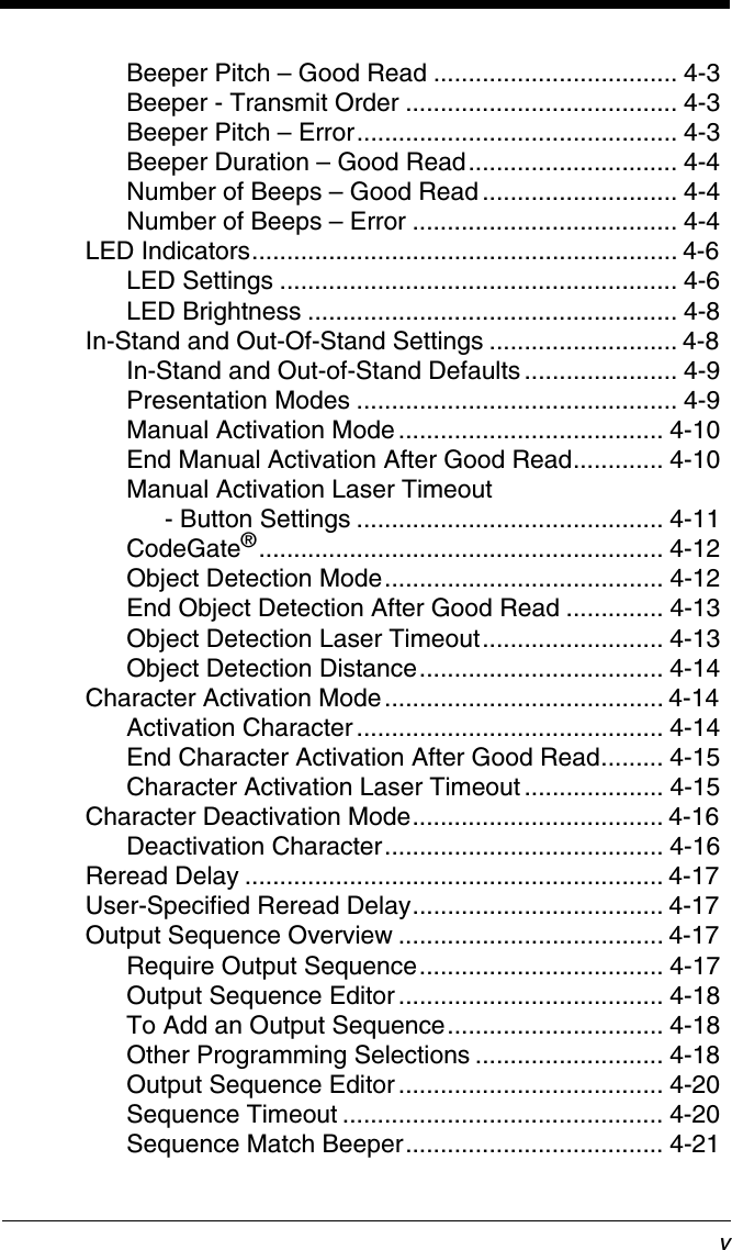
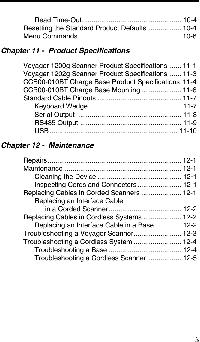
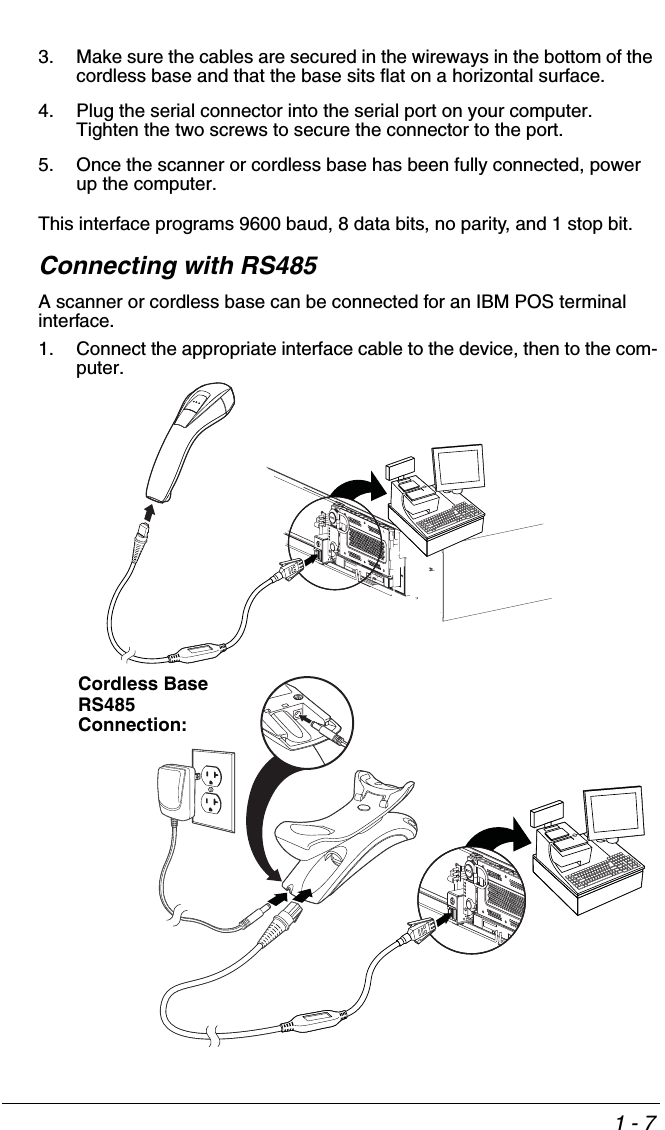
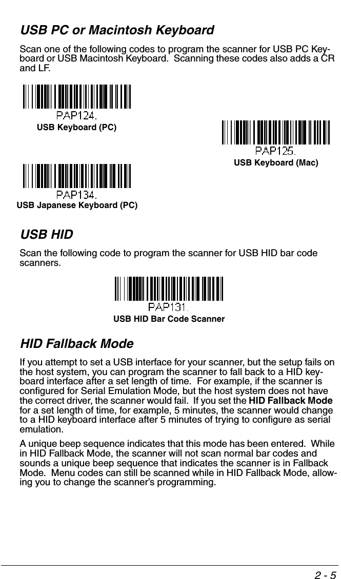
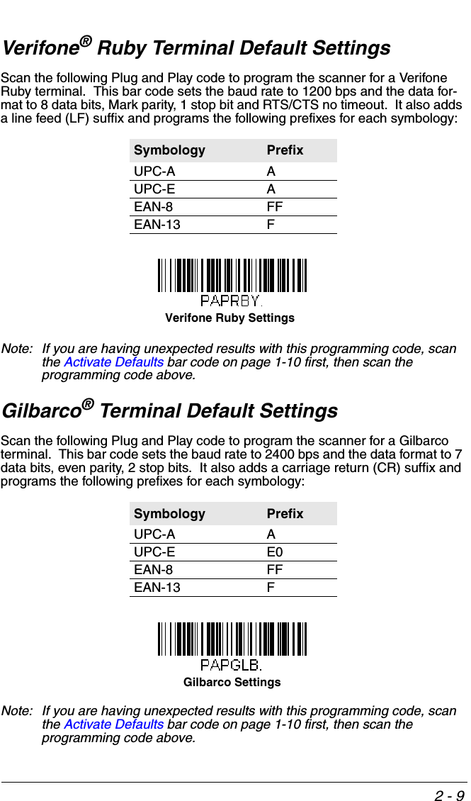
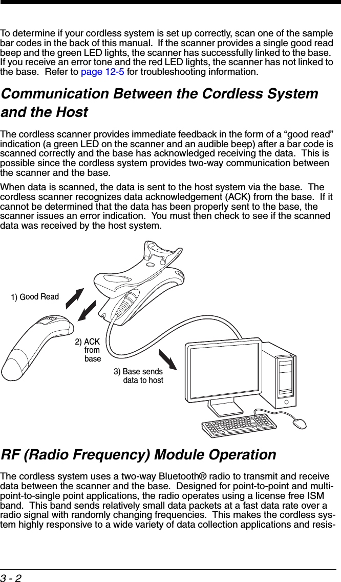
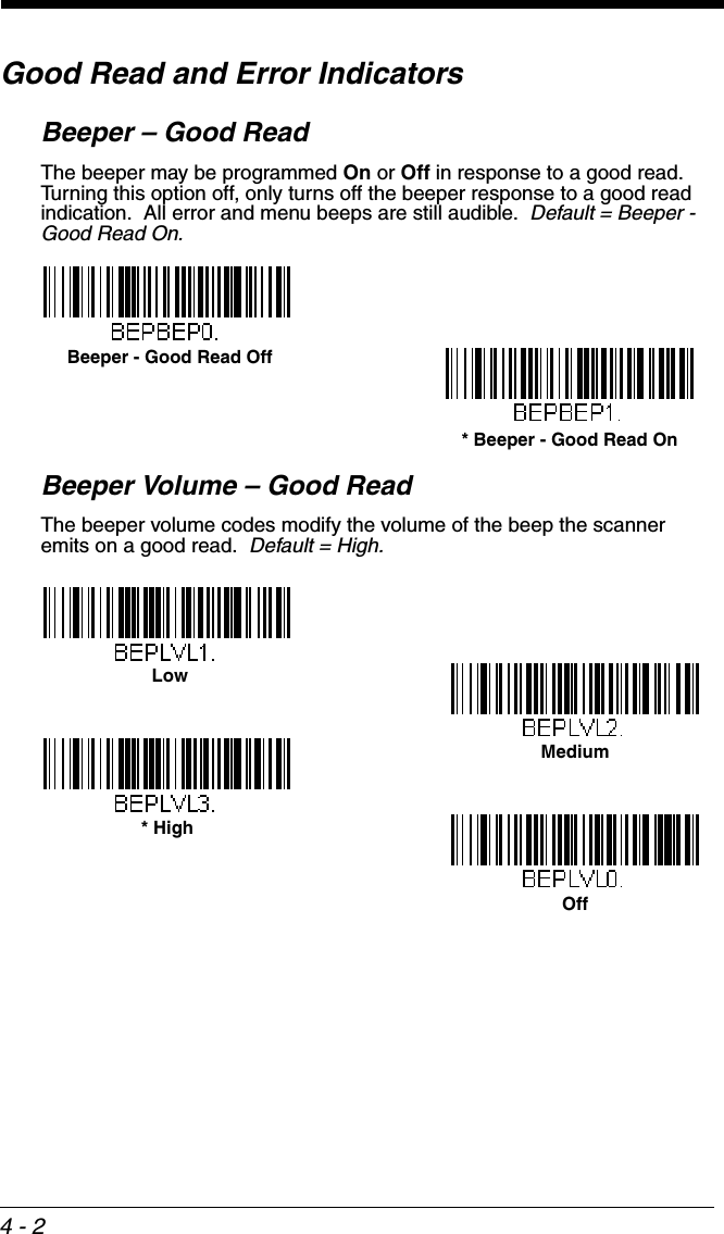
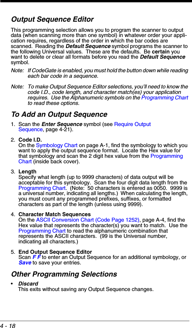
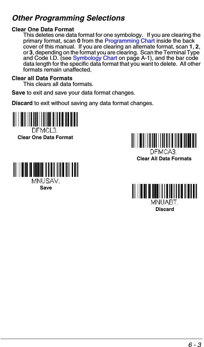
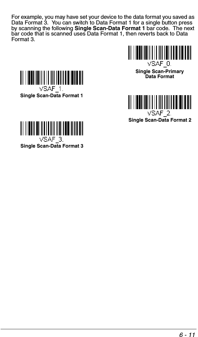
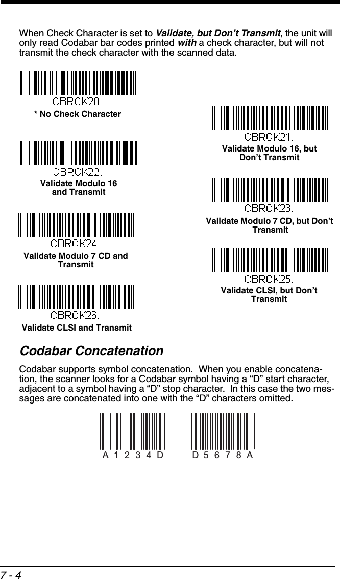
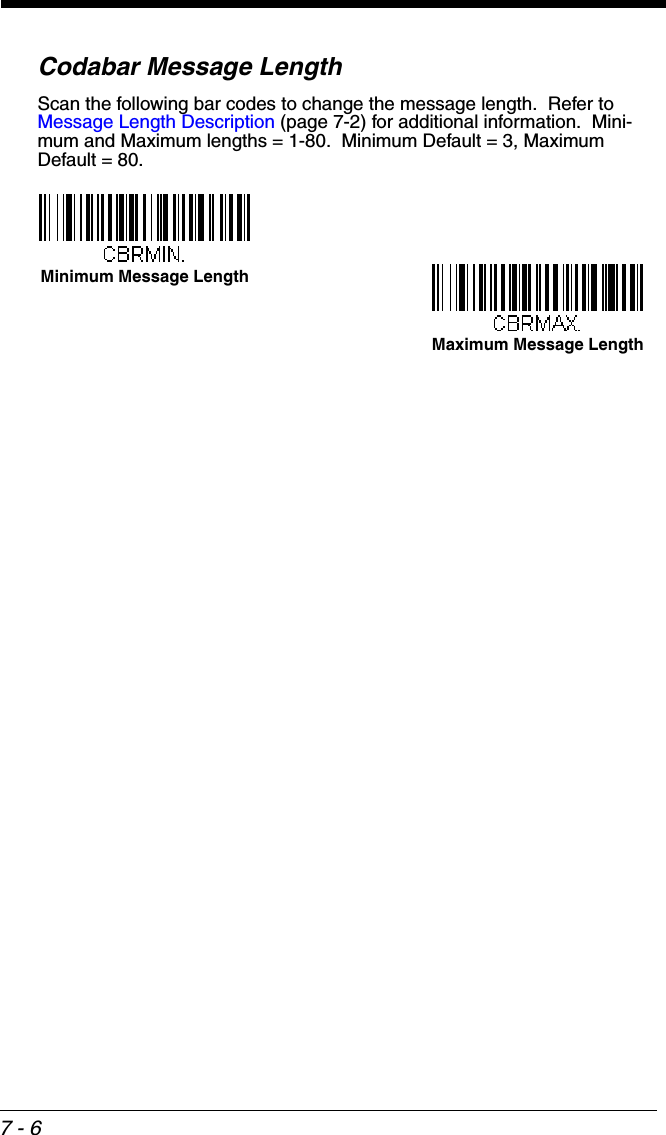
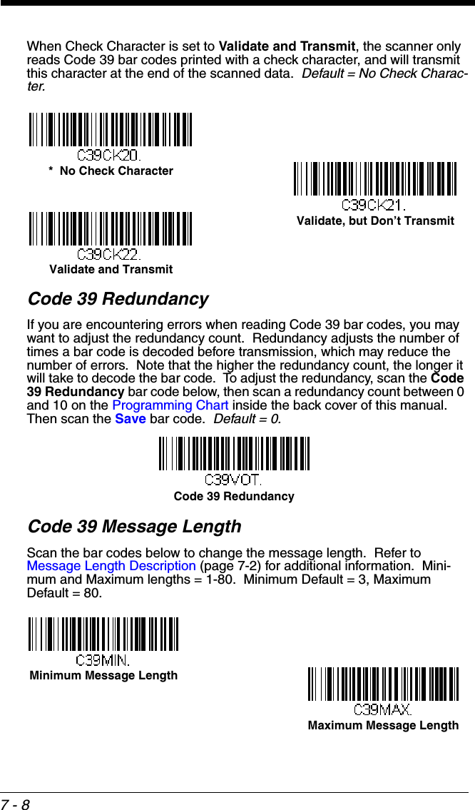
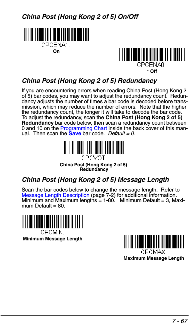
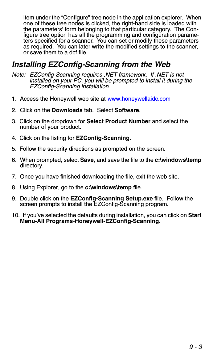
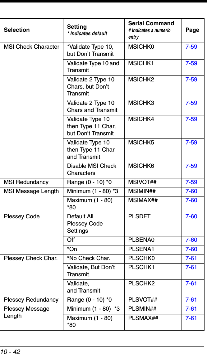
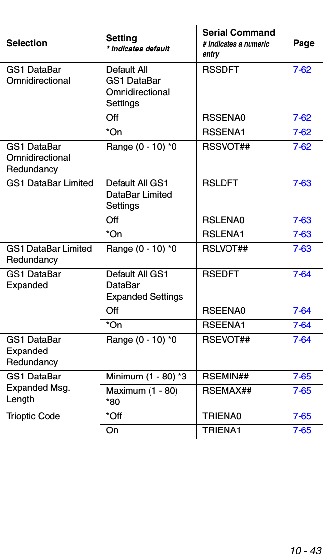
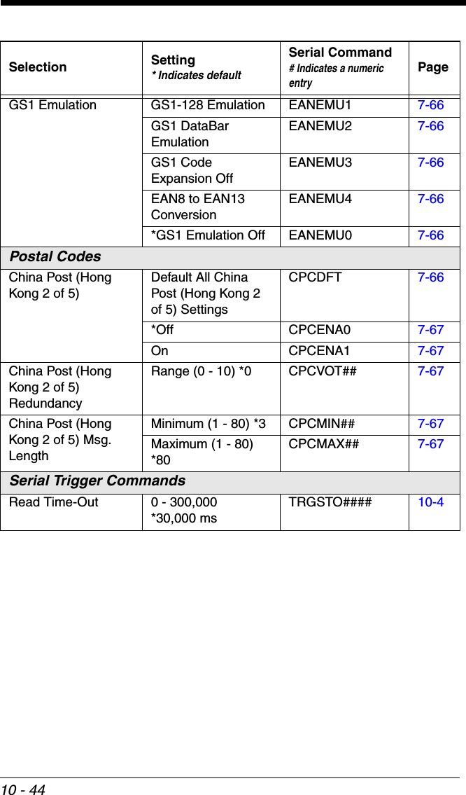
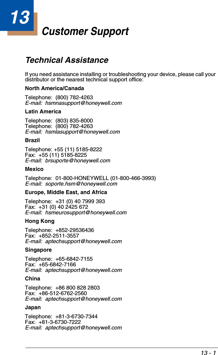
![7 - 65GS1 DataBar Expanded Message LengthScan the bar codes below to change the message length. Refer to Message Length Description (page 7-2) for additional information. Mini-mum and Maximum lengths = 1-80. Minimum Default = 3, Maximum Default = 80.Trioptic CodeTrioptic Code is used for labeling magnetic storage media.GS1 EmulationThe scanner can automatically format the output from any GS1 data carrier to emulate what would be encoded in an equivalent GS1-128 or GS1 DataBar symbol. GS1 data carriers include UPC-A and UPC-E, EAN-13 and EAN-8, ITF-14, GS1-128, and GS1-128 DataBar and GS1 Composites. (Any applica-tion that accepts GS1 data can be simplified since it only needs to recognize one data carrier type.)If GS1-128 Emulation is scanned, all retail codes (U.P.C., UPC-E, EAN8, EAN13) are expanded out to 16 digits. If the AIM ID is enabled, the value will be the GS1-128 AIM ID, ]C1 (see Symbology Chart on page A-1).If GS1 DataBar Emulation is scanned, all retail codes (U.P.C., UPC-E, EAN8, EAN13) are expanded out to 16 digits. If the AIM ID is enabled, the value will be the GS1-DataBar AIM ID, ]em (see Symbology Chart on page A-1).If GS1 Code Expansion Off is scanned, retail code expansion is disabled, and UPC-E expansion is controlled by the UPC-E0 Expand (page 7-41) setting. If the AIM ID is enabled, the value will be the GS1-128 AIM ID, ]C1 (see Symbology Chart on page A-1).Minimum Message LengthMaximum Message LengthOn* Off](https://usermanual.wiki/Honeywell/BT010M.User-Manual/User-Guide-1663573-Page-199.png)

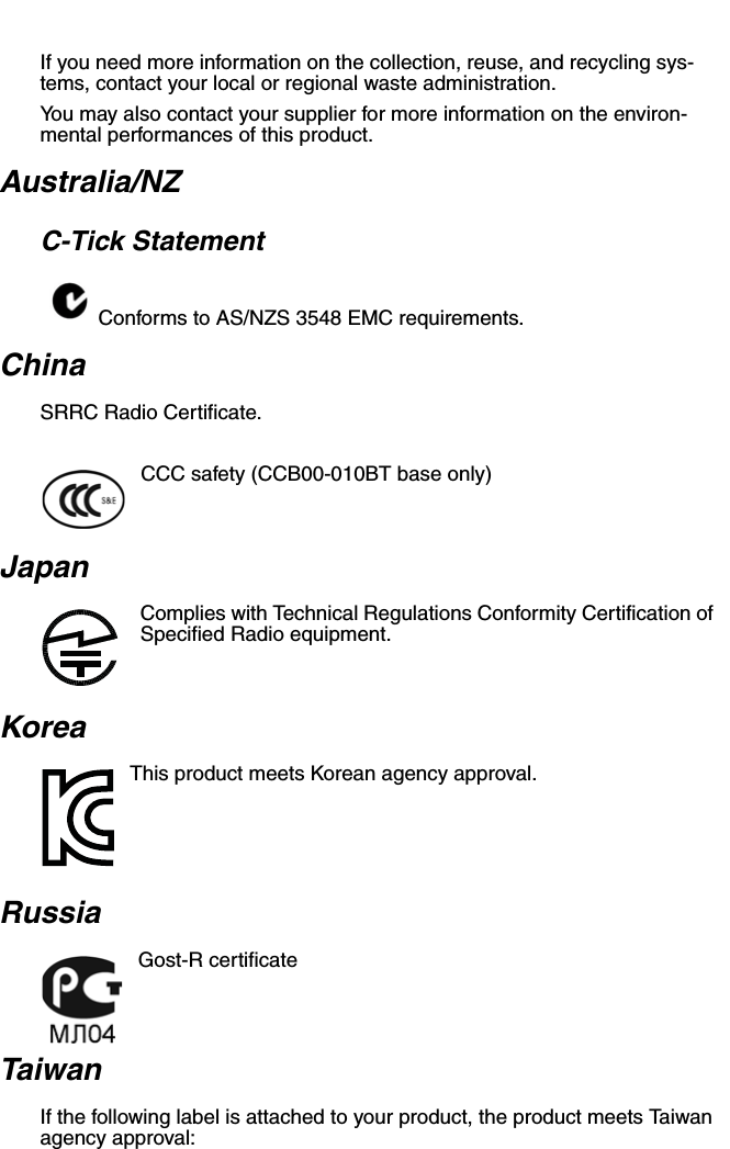
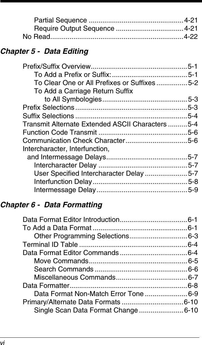
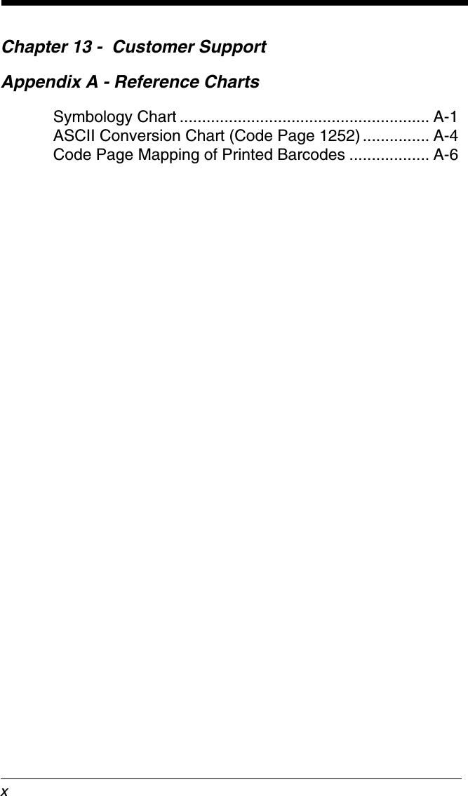
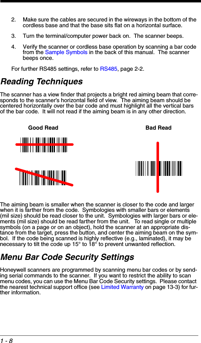
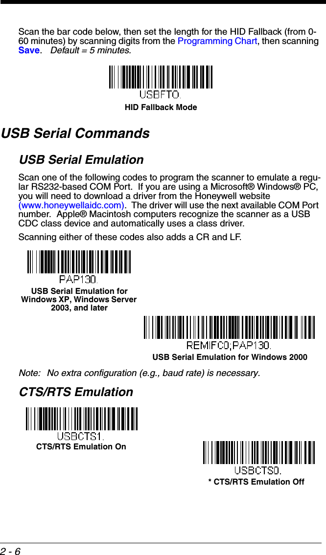
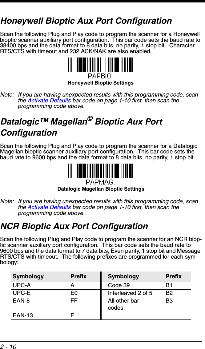
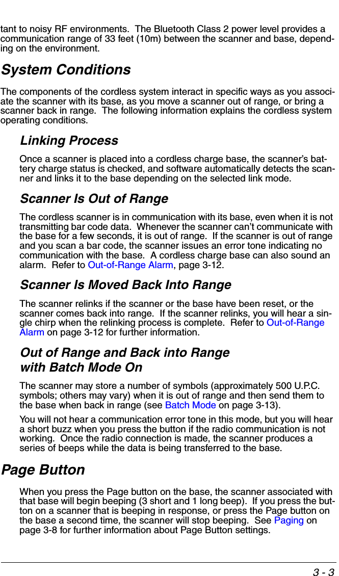
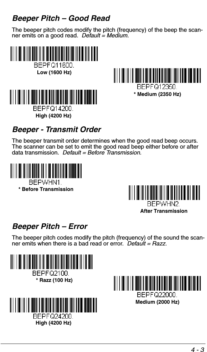
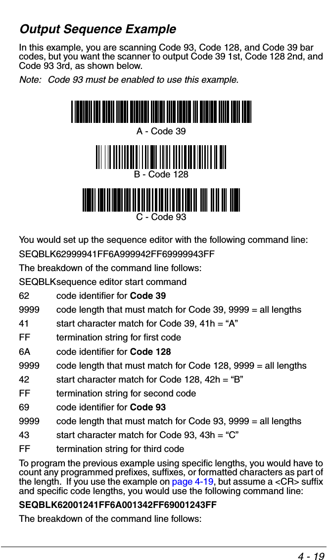
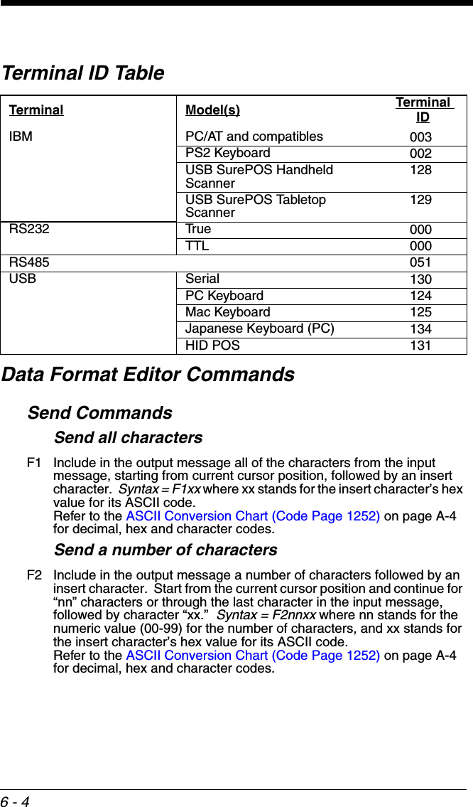
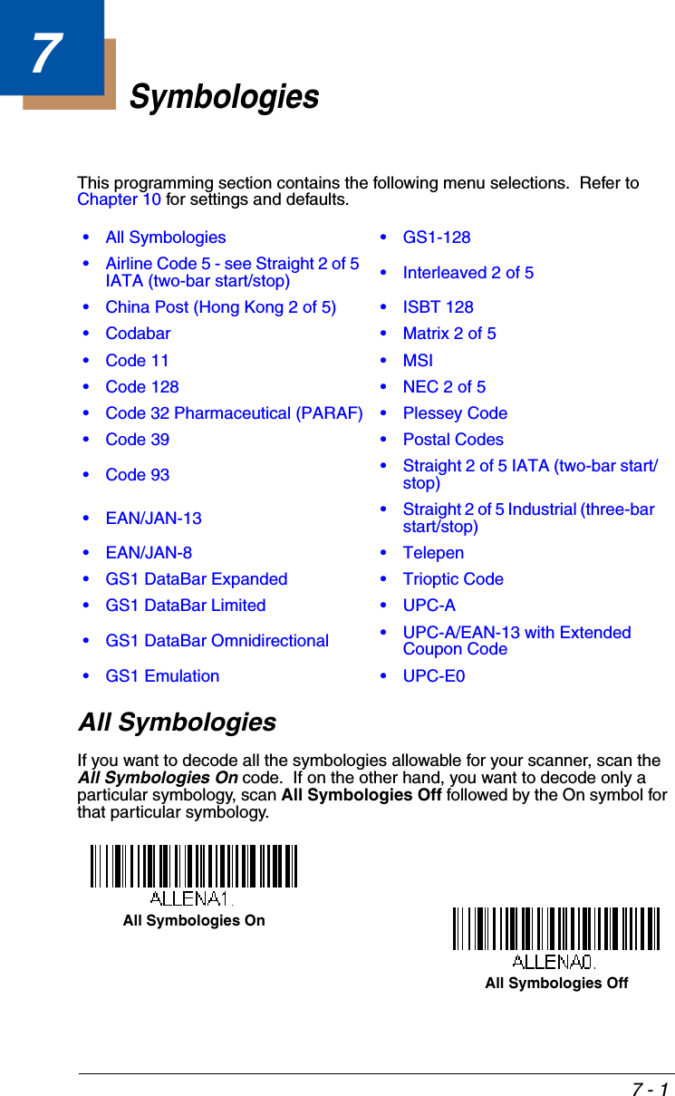
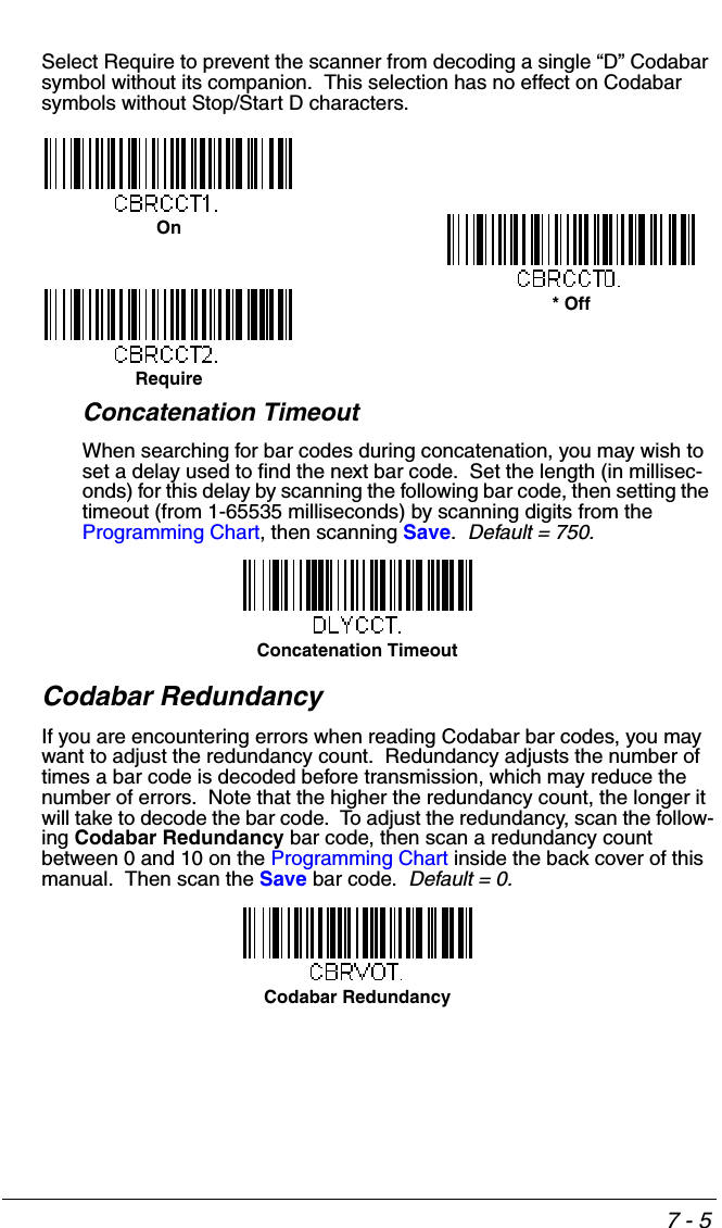
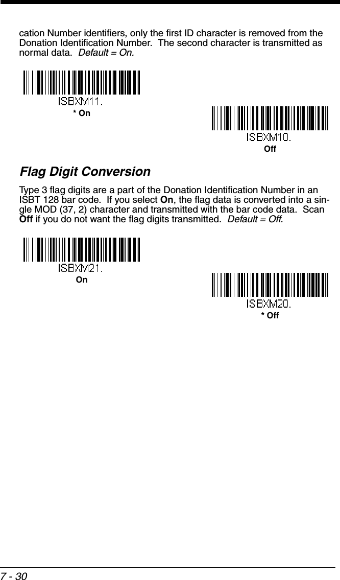
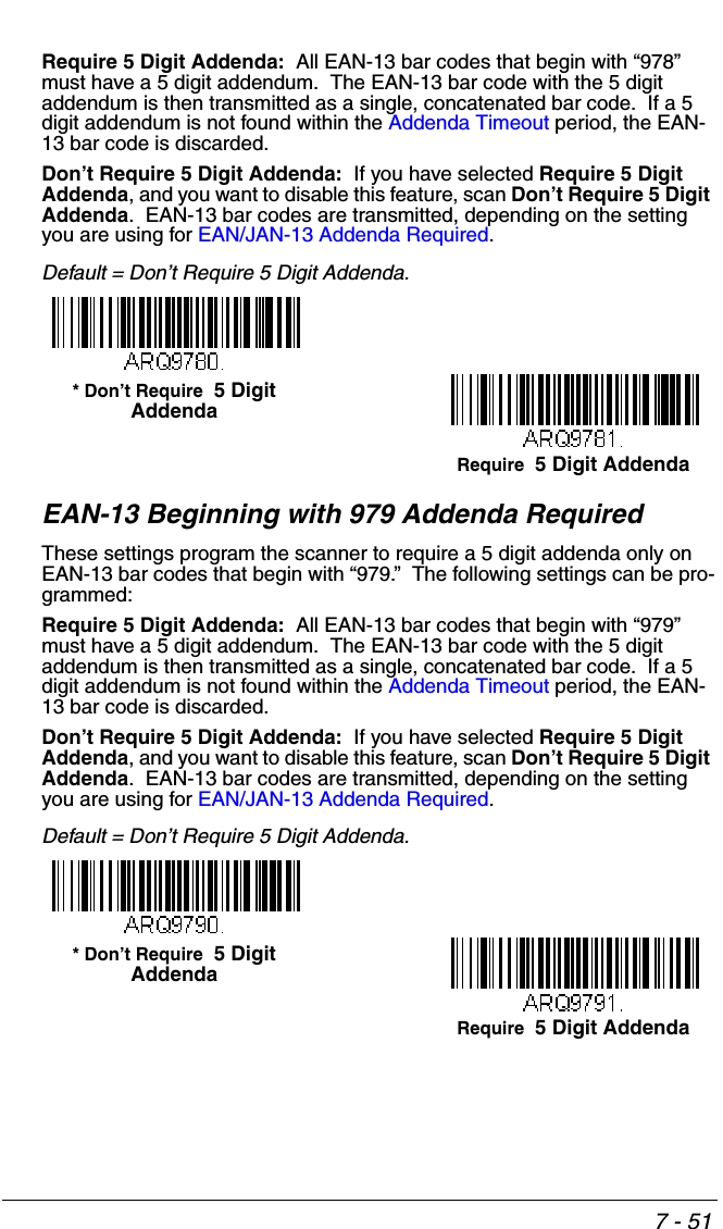
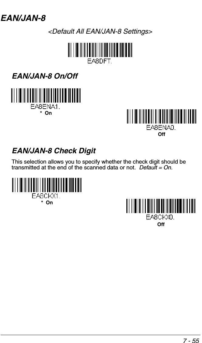
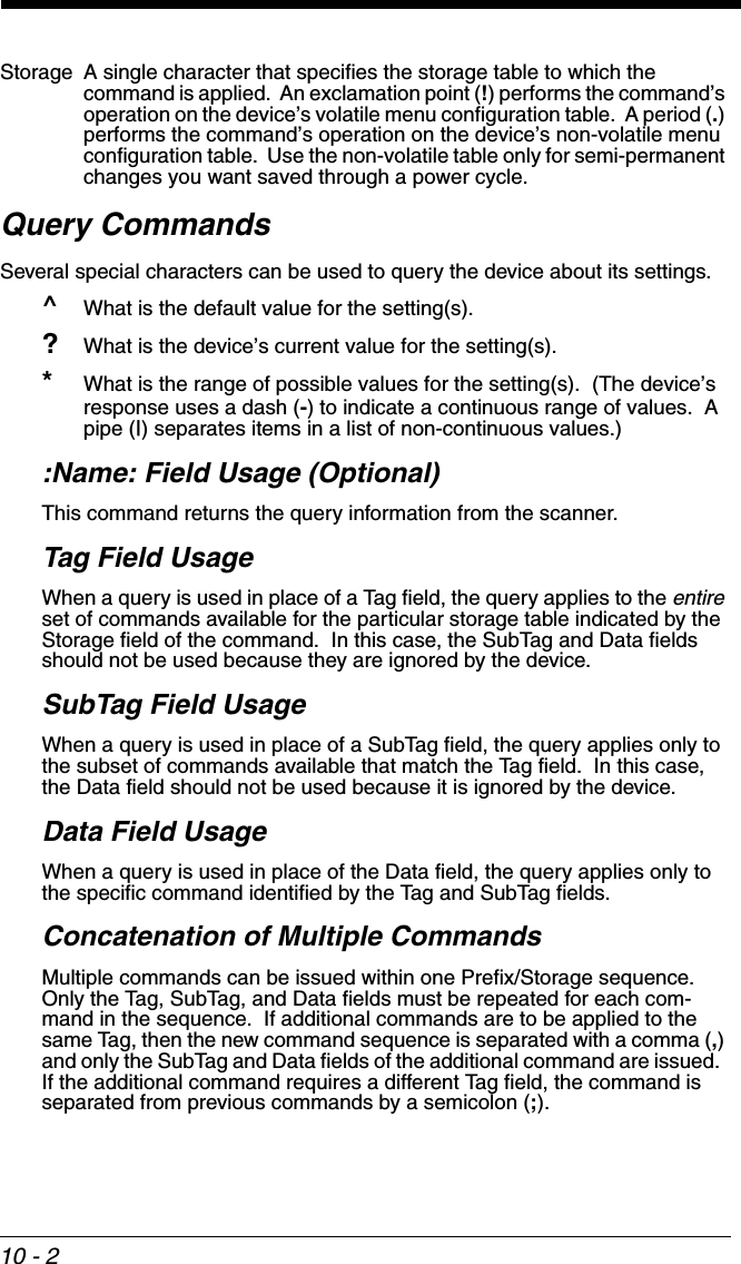
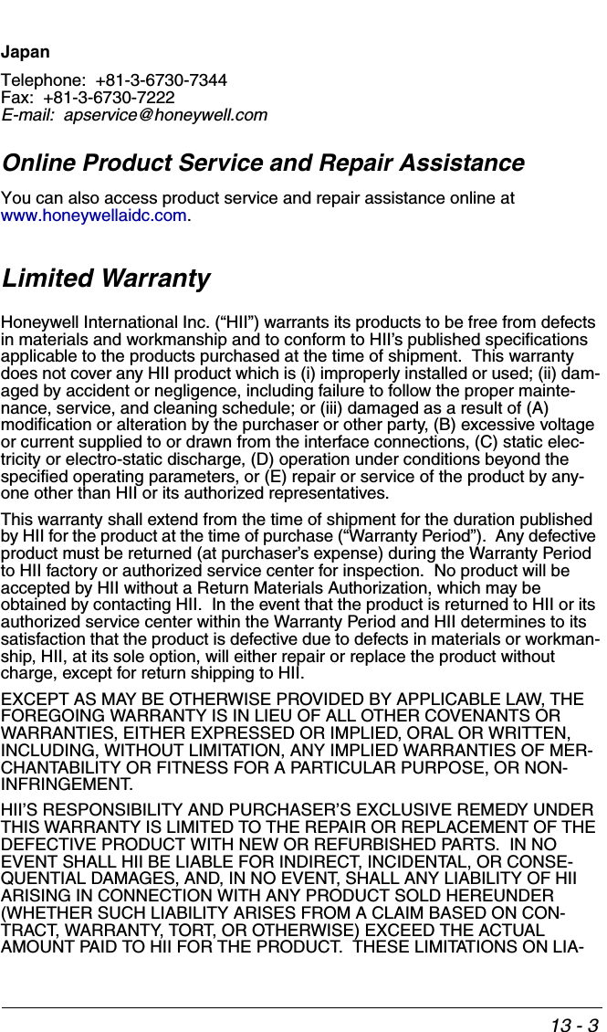
![8 - 18Interface KeysKeyboard Function RelationshipsThe following Keyboard Function Code, Hex/ASCII Value, and Full ASCII “CTRL”+ relationships apply to all terminals that can be used with the scanner. Refer to page 2-17 enable Control + ASCII mode.Function Code HEX/ASCII Value Full ASCII “CTRL” +NUL 00 @SOH 01 ASTX 02 BETX 03 CEOT 04 DENQ 05 EACK 06 FBEL 07 GBS 08 HHT 09 ILF 0A JVT 0B KFF 0C LCR 0D MSO 0E NSI 0F ODLE 10 PDC1 11 QDC2 12 RDC3 13 SDC4 14 TNAK 15 USYN 16 VETB 17 WCAN 18 XEM 19 YSUB 1A ZESC 1B [FS 1C \GS 1D ]RS 1E ^US 1F _](https://usermanual.wiki/Honeywell/BT010M.User-Manual/User-Guide-1663573-Page-203.png)
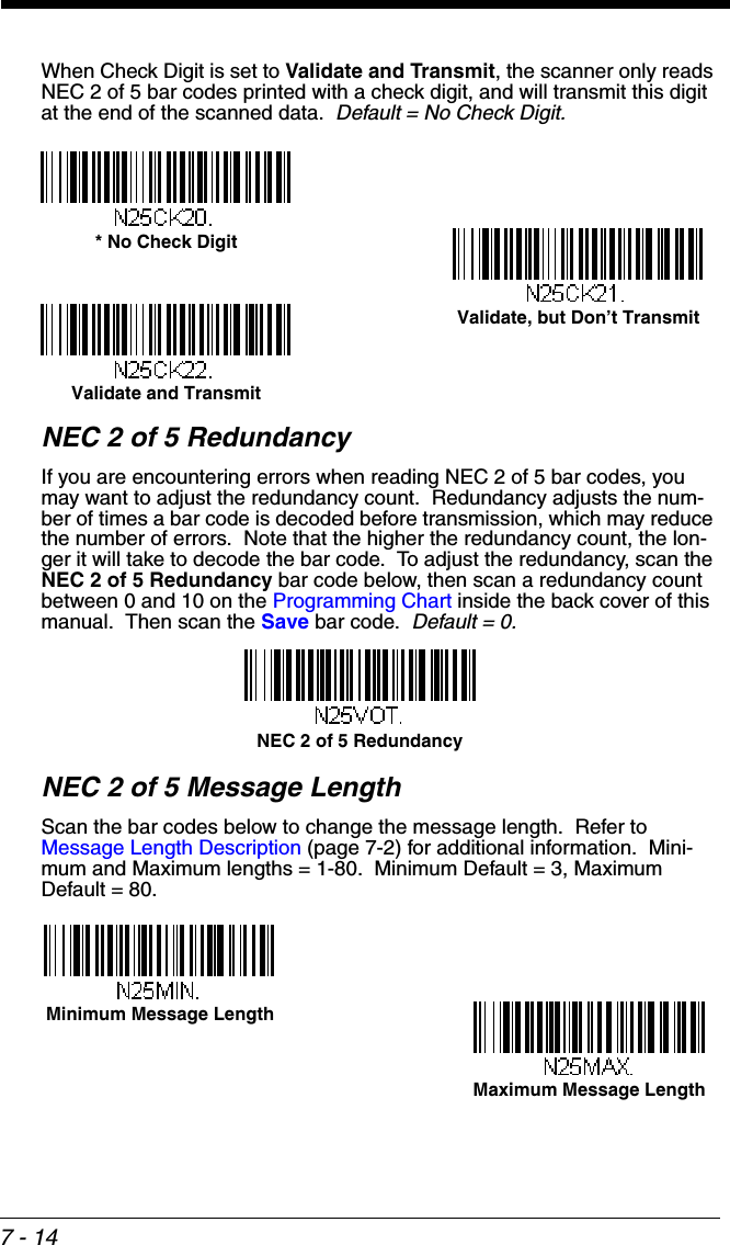
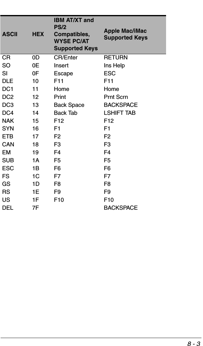
![8 - 2The last five characters in the Full ASCII “CTRL”+ column ( [ \ ] 6 - ), apply to US only. The following chart indicates the equivalents of these five characters for different countries.Note: Not all countries may be supported by your device.Supported Interface KeysCountry CodesUnited States [ \ ] 6 -Belgium [ < ] 6 -Scandinavia 8 < 9 6 -France ^8$6=Germany à + 6 -Italy \ + 6 -Switzerland <. . 6 -United Kingdom [ ¢ ] 6 -Denmark 8 \ 9 6 -Norway 8\ 96-Spain [ \ ] 6 -ASCII HEXIBM AT/XT and PS/2 Compatibles, WYSE PC/ATSupported KeysApple Mac/iMac Supported KeysNUL 00 Reserved ReservedSOH 01 Enter (KP) Enter/Numpad EnterSTX 02 Cap Lock CAPSETX 03 ALT make ALT makeEOT 04 ALT break ALT breakENQ 05 CTRL make CNTRL makeACK 06 CTRL break CNTRL breakBEL 07 CR/Enter RETURNBS 08 Reserved APPLE makeHT 09 Tab TABLF 0A Reserved APPLE breakVT 0B Tab TABFF 0C Delete Del](https://usermanual.wiki/Honeywell/BT010M.User-Manual/User-Guide-1663573-Page-204.png)


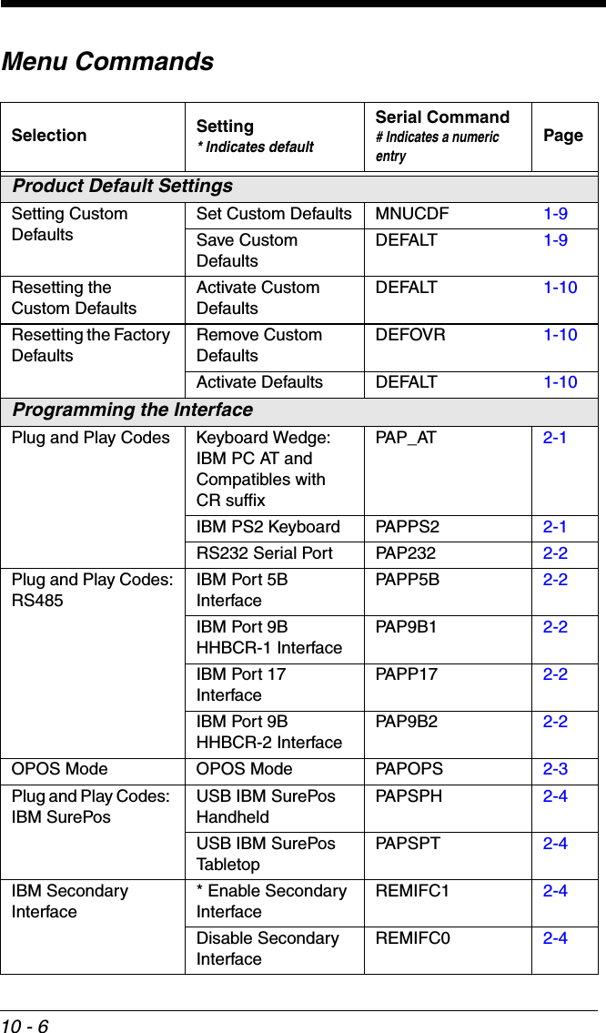
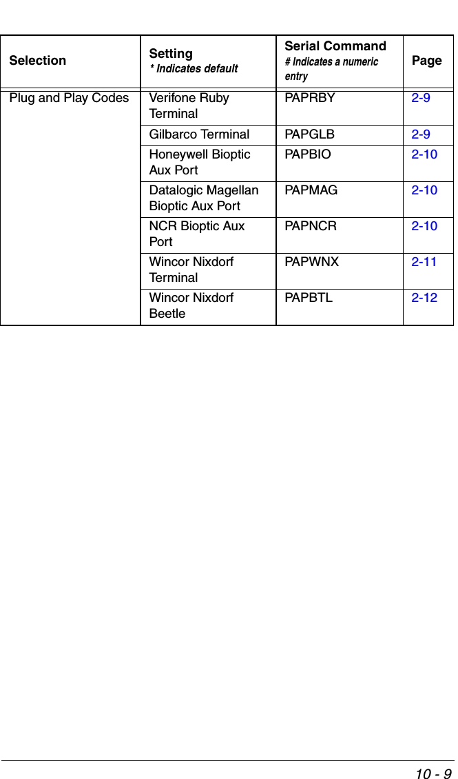
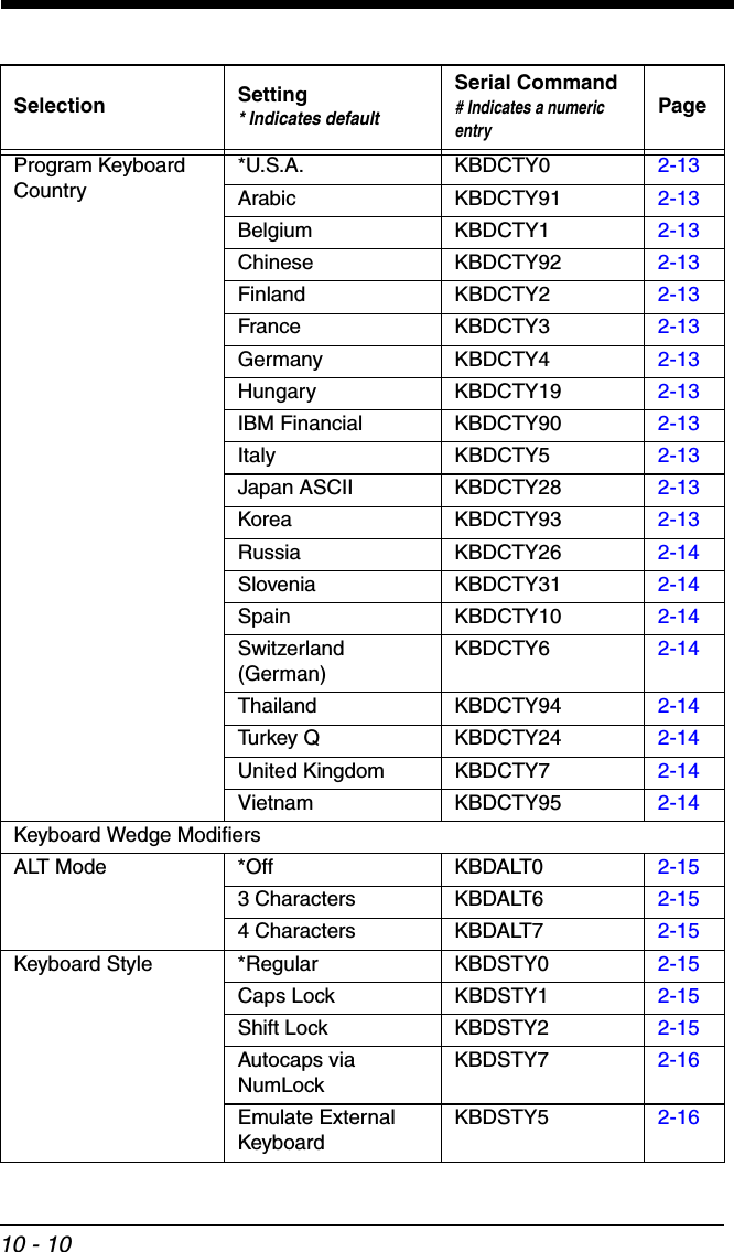
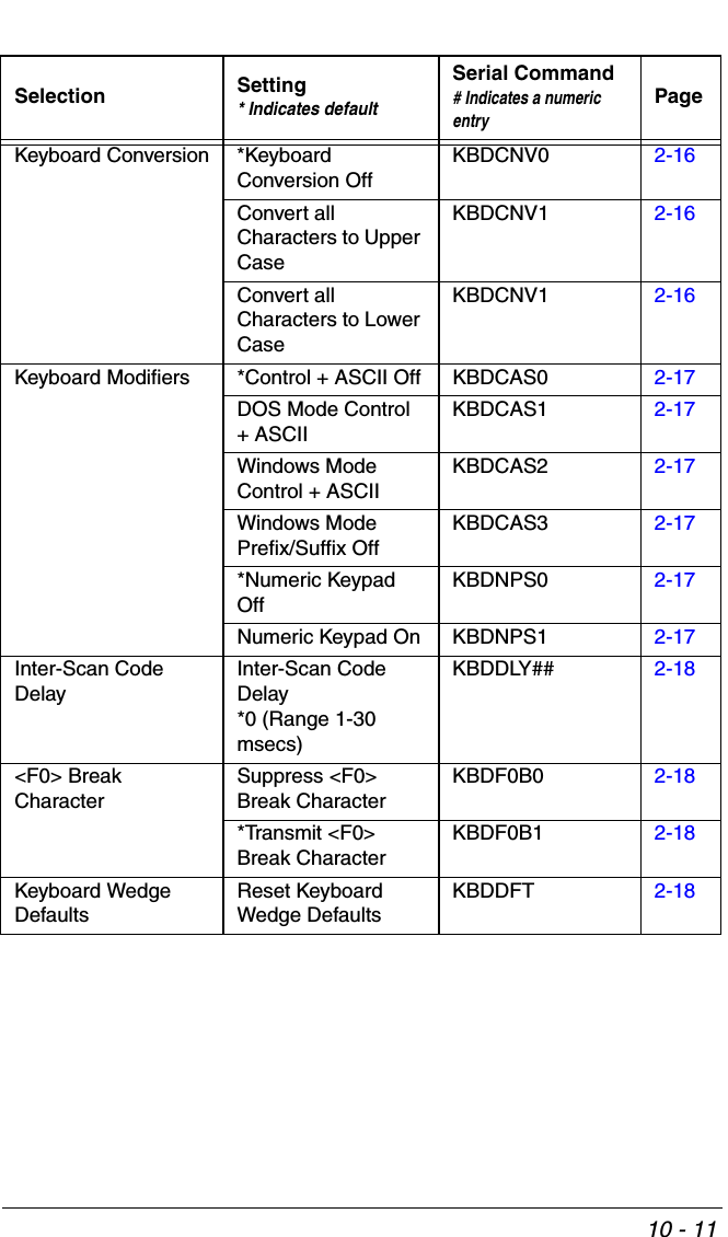
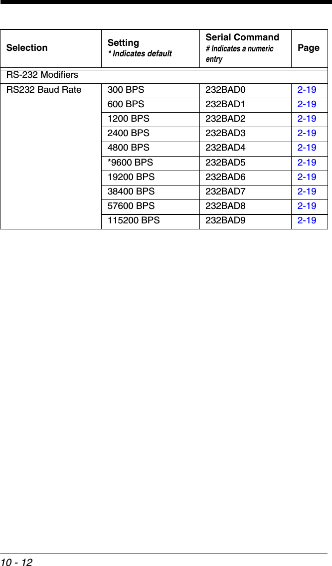
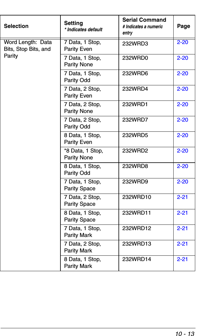
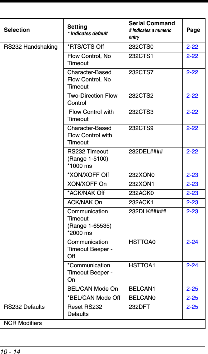
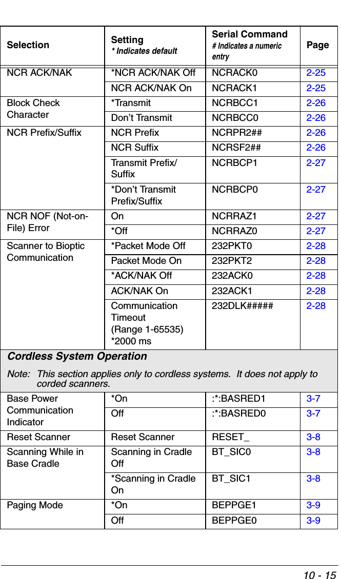
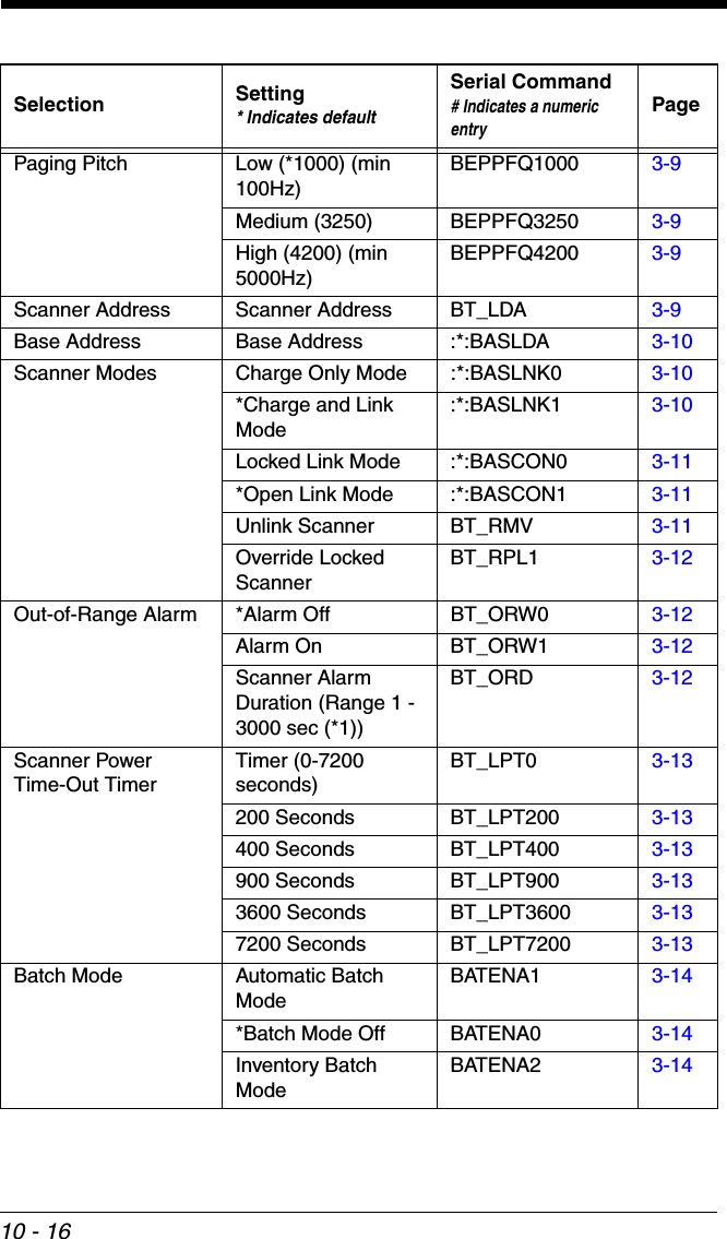
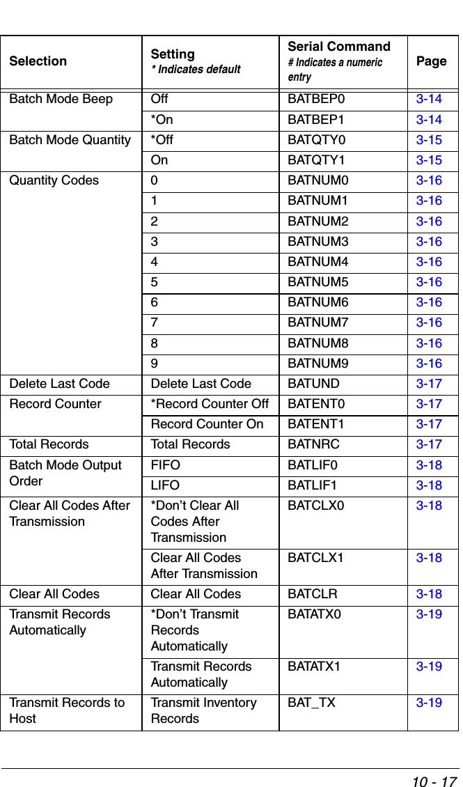
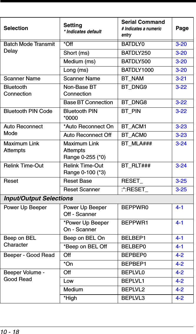
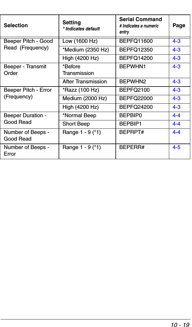
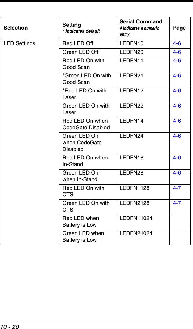
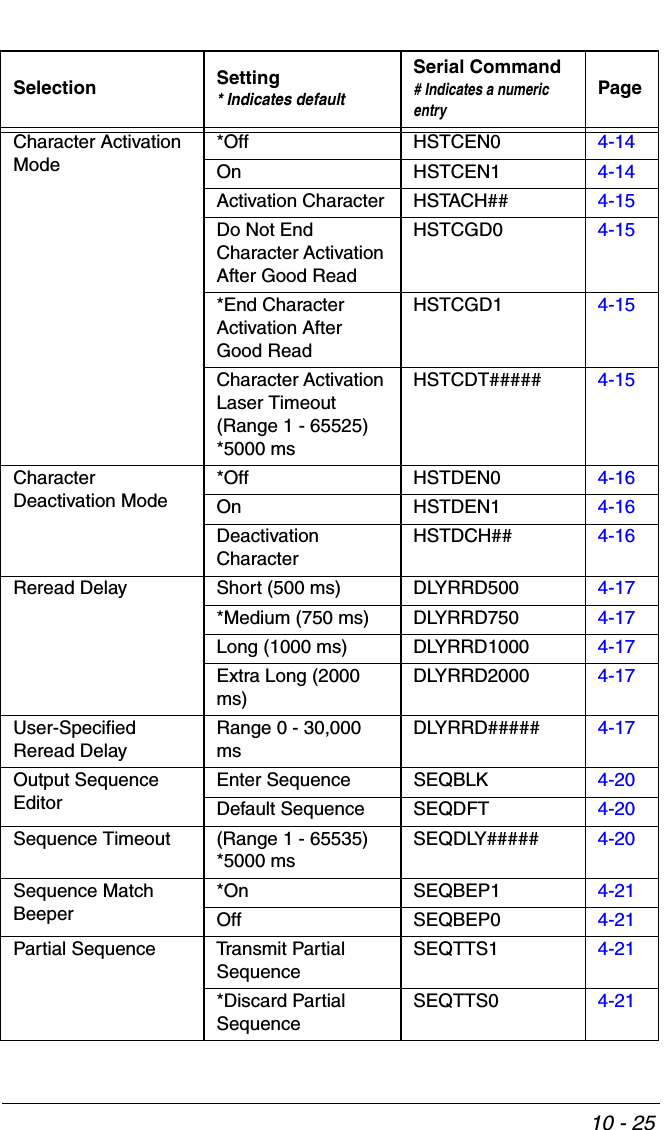
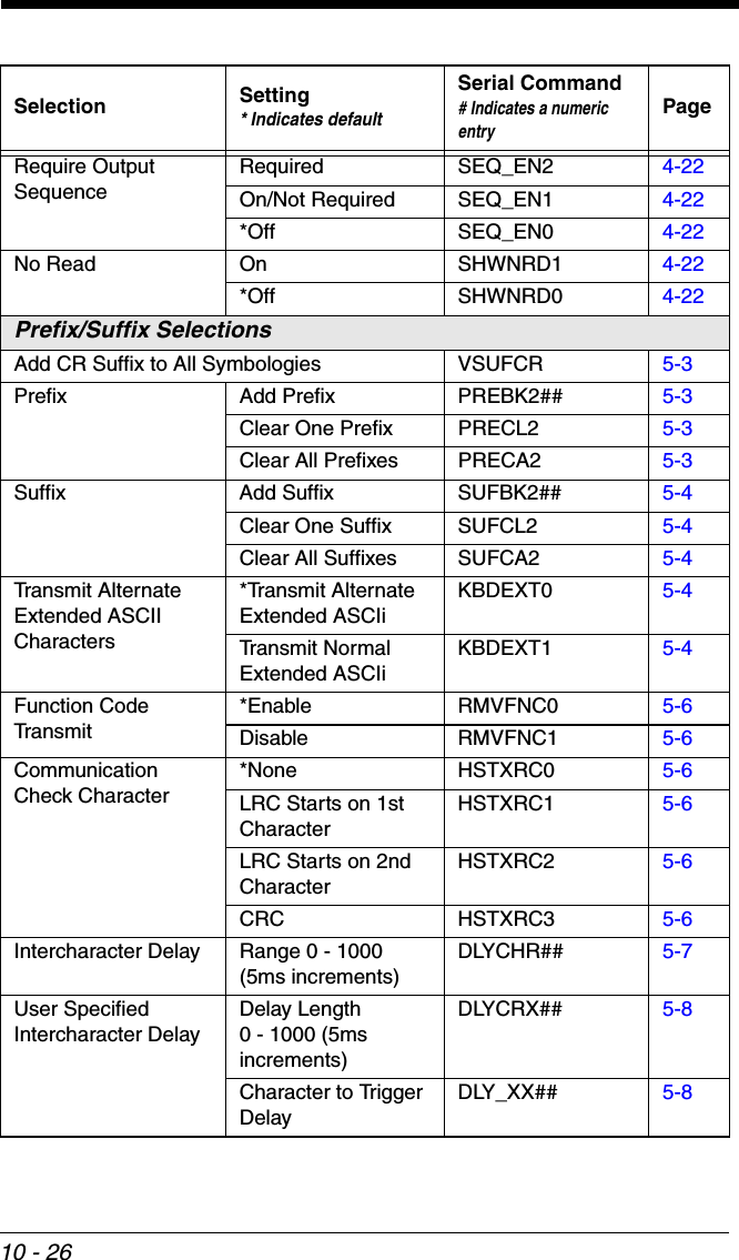
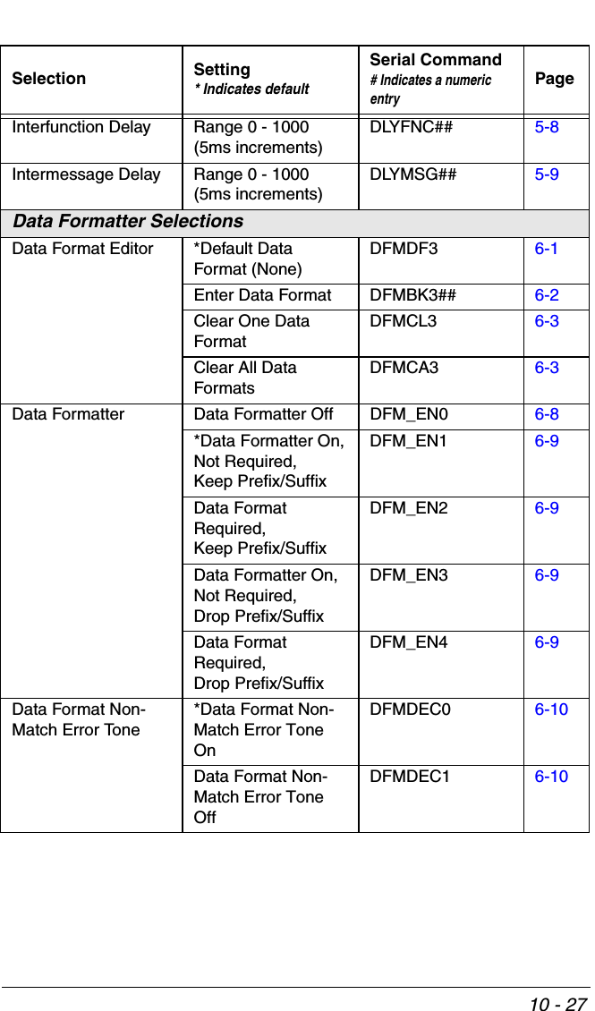
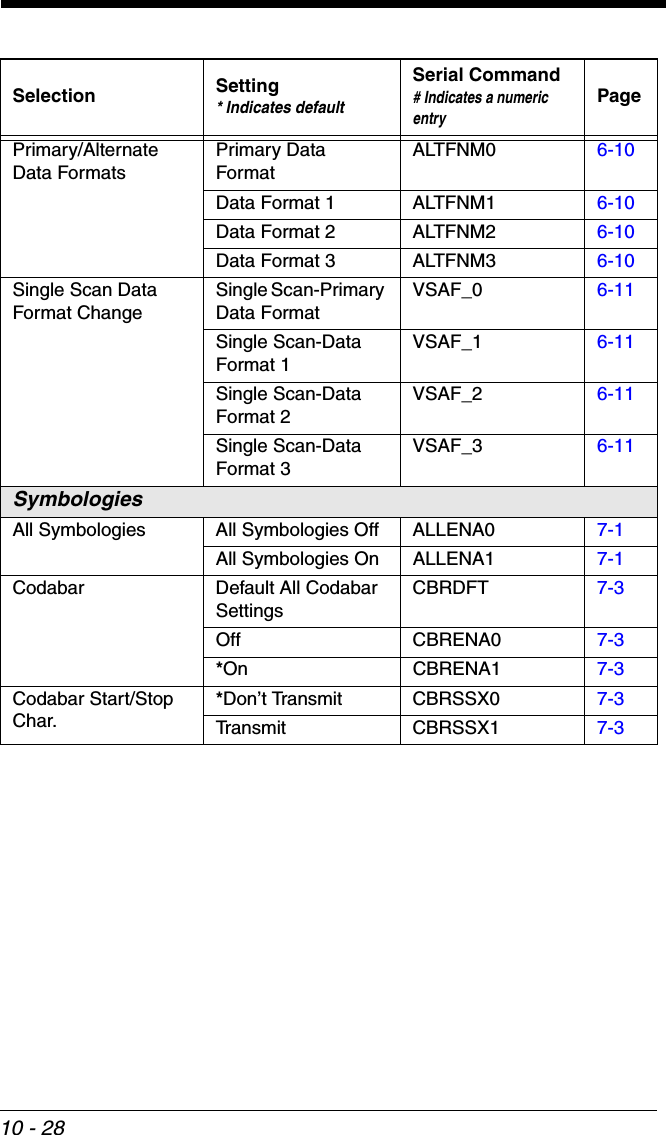
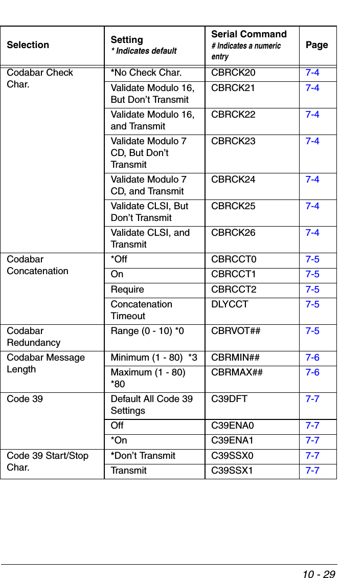
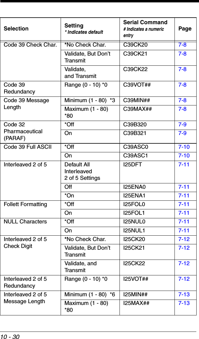
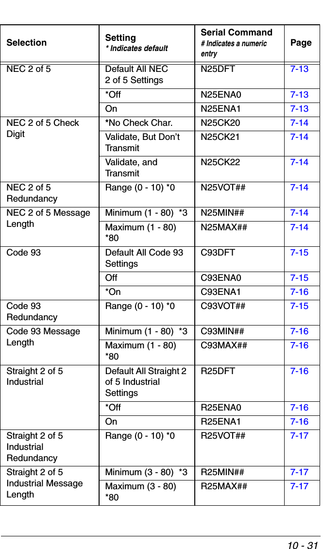
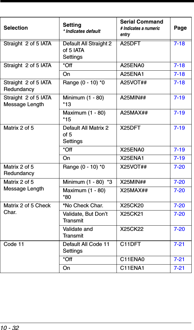
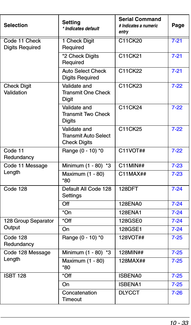
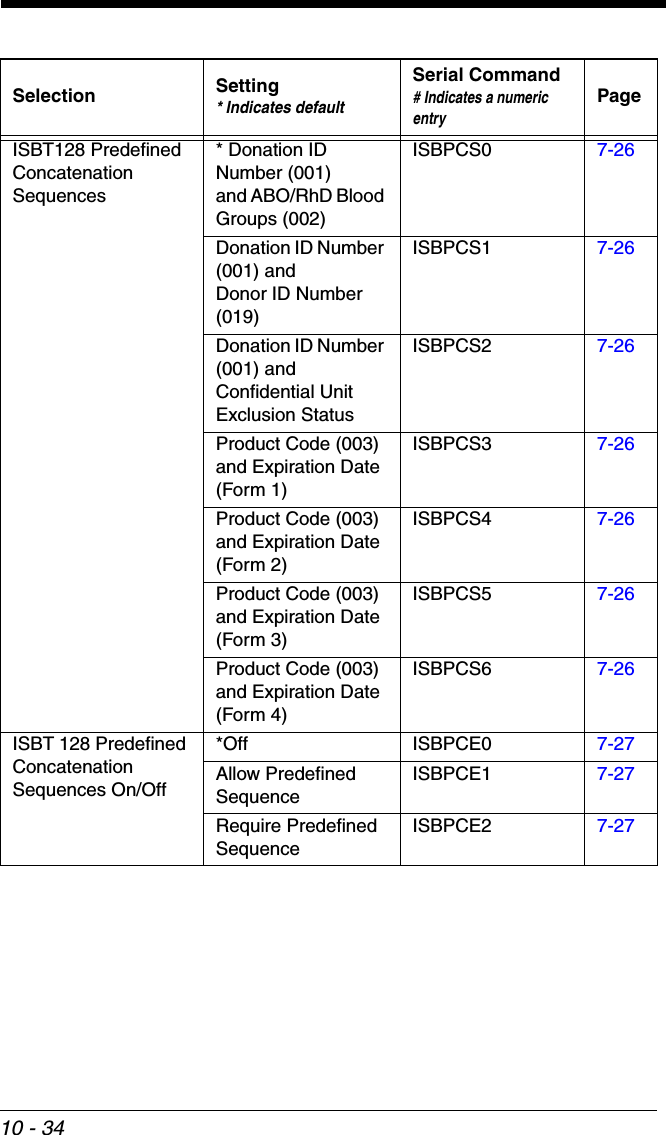
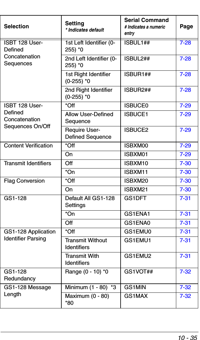
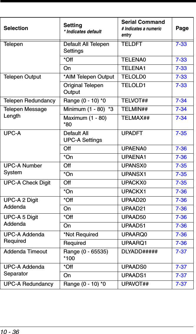
![10 - 110Serial Programming CommandsThe serial programming commands can be used in place of the programming bar codes. Both the serial commands and the programming bar codes will pro-gram the scanner. For complete descriptions and examples of each serial pro-gramming command, refer to the corresponding programming bar code in this manual.The device must be set to an RS232 interface (see page 2-1). The following commands can be sent via a PC COM port using terminal emulation software.ConventionsThe following conventions are used for menu and query command descriptions:parameterA label representing the actual value you should send as part of a command.[option] An optional part of a command.{Data} Alternatives in a command.bold Names of menus, menu commands, buttons, dialog boxes, and windows that appear on the screen.Menu Command SyntaxMenu commands have the following syntax (spaces have been used for clarity only):Prefix [:Name:] Tag SubTag {Data} [, SubTag {Data}] [; Tag SubTag {Data}] […] StoragePrefix Three ASCII characters: SYN M CR (ASCII 22,77,13).:Name: To send information to the scanner (with the base connected to host), use :Voyager: The default factory setting for a Voyager scanner is Voyager scanner. If the name is not known, a wildcard (*) can be used :*:.Note: Since the base stores all work group settings and transfers to them to scanner once they are linked, changes are typically done to the base and not to the scanner.Tag A 3 character case-insensitive field that identifies the desired menu command group. For example, all RS232 configuration settings are identified with a Tag of 232.SubTag A 3 character case-insensitive field that identifies the desired menu command within the tag group. For example, the SubTag for the RS232 baud rate is BAD.Data The new value for a menu setting, identified by the Tag and SubTag.](https://usermanual.wiki/Honeywell/BT010M.User-Manual/User-Guide-1663573-Page-211.png)
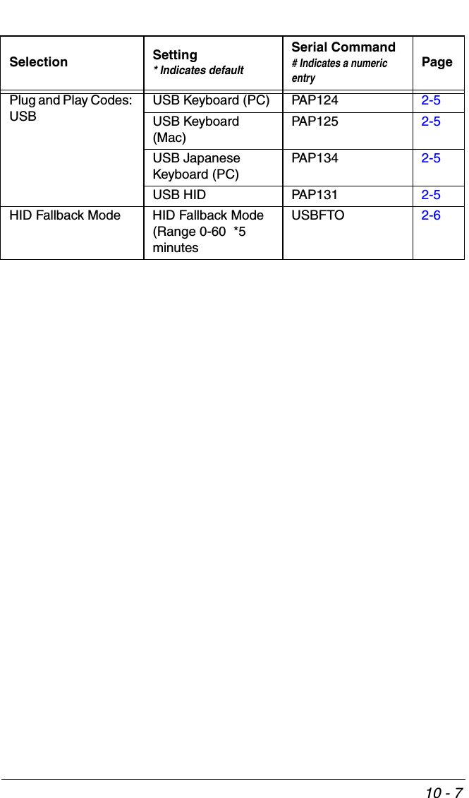
![10 - 3ResponsesThe device responds to serial commands with one of three responses:ACK Indicates a good command which has been processed.ENQ Indicates an invalid Tag or SubTag command. NAK Indicates the command was good, but the Data field entry was out of the allowable range for this Tag and SubTag combination, e.g., an entry for a minimum message length of 100 when the field will only accept 2 characters.When responding, the device echoes back the command sequence with the status character inserted directly before each of the punctuation marks (the period, exclamation point, comma, or semicolon) in the command.Examples of Query CommandsIn the following examples, a bracketed notation [ ] depicts a non-displayable response.Example: What is the range of possible values for Codabar Coding Enable?Enter: cbrena*.Response: CBRENA0-1[ACK]This response indicates that Codabar Coding Enable (CBRENA) has a range of values from 0 to 1 (off and on). Example: What is the default value for Codabar Coding Enable?Enter: cbrena^.Response: CBRENA1[ACK]This response indicates that the default setting for Codabar Coding Enable (CBRENA) is 1, or on. Example: What is the device’s current setting for Codabar Coding Enable?Enter: cbrena?.Response: CBRENA1[ACK]This response indicates that the device’s Codabar Coding Enable (CBRENA) is set to 1, or on. Example: What are the device’s settings for all Codabar selections?Enter: cbr?.Response: CBRENA1[ACK],SSX0[ACK],CK20[ACK],CCT1[ACK],MIN2[ACK],](https://usermanual.wiki/Honeywell/BT010M.User-Manual/User-Guide-1663573-Page-213.png)
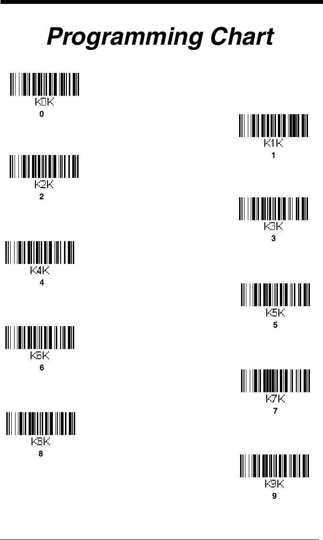
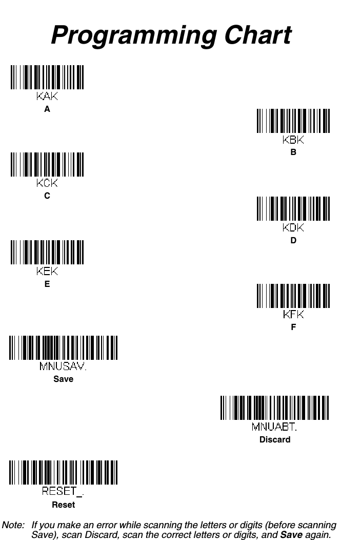
![10 - 4MAX60[ACK],DFT[ACK].This response indicates that the device’s Codabar Coding Enable (CBRENA) is set to 1, or on; the Start/Stop Character (SSX) is set to 0, or Don’t Transmit; the Check Character (CK2) is set to 0, or Not Required;concatenation (CCT) is set to 1, or Enabled; the Minimum Message Length (MIN) is set to 2 characters; the Maximum Message Length (MAX) is set to 60 characters; and the Default setting (DFT) has no value. Serial Trigger CommandsYou can activate and deactivate the scanner with serial trigger commands. The button is activated and deactivated by sending the following commands:Activate: SYN T CRDeactivate: SYN U CRThe scanner scans until a bar code has been read or until the deactivate com-mand is sent. The scanner can also be set to turn itself off after a specified time has elapsed (see Read Time-Out, which follows).Read Time-OutUse this selection to set a time-out (in milliseconds) of the scanner’s button when using serial commands to trigger the scanner. Once the scanner has timed out, you can activate the scanner either by pressing the button or using a serial trigger command. After scanning the Read Time-Out bar code, set the time-out duration (from 0-300,000 milliseconds) by scanning digits on the Programming Chart inside the back cover, then scanning Save. Default = 30,000 ms.Resetting the Standard Product DefaultsIf you aren’t sure what programming options are in your scanner, or you’ve changed some options and want the factory default settings restored, scan the Standard Product Default Settings bar code below.Read Time-OutStandard Product Default Settings](https://usermanual.wiki/Honeywell/BT010M.User-Manual/User-Guide-1663573-Page-214.png)
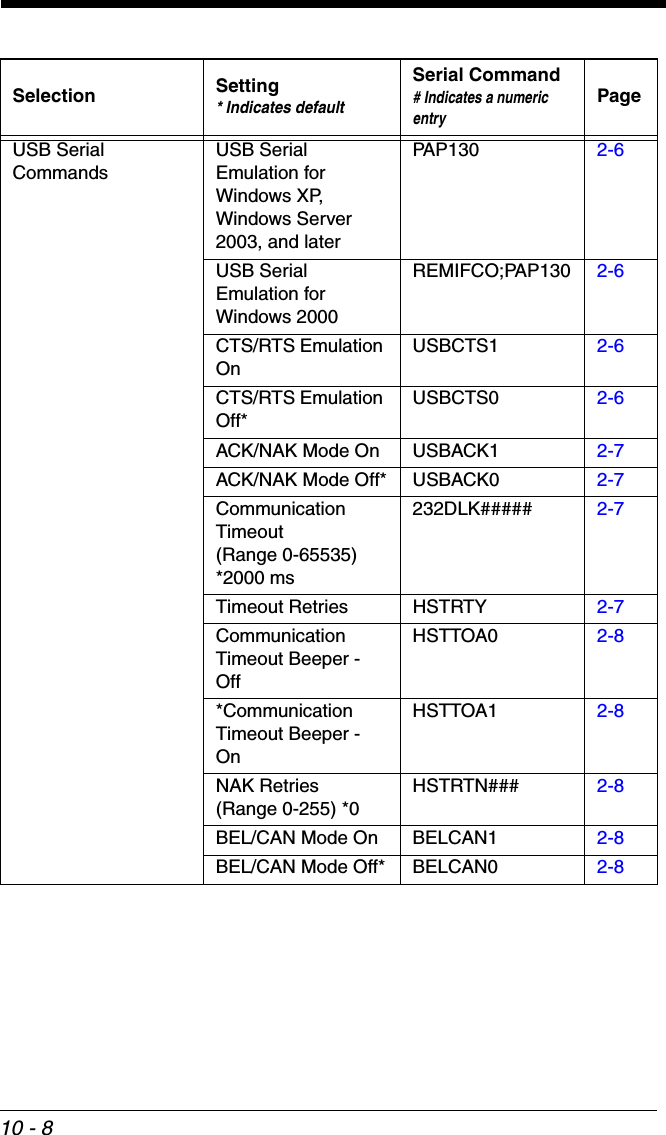


![A - 1AReference ChartsSymbology ChartNote: Not all symbologies may be supported by your device.Symbology AIM IDPossible AIM ID Modifiers (m)Code ID (hex)All Symbologies (0x99)Australian Post ]X0 A (0x41)Aztec Code ]zm0-9, A-C z (0x7A)British Post ]X0 B (0x42)Canadian Post ]X0 C (0x43)China Post ]X0 Q (0x51)Chinese Sensible Code (Han Xin Code)]X0 H (0x48)Codabar ]Fm0-1 a (0x61)Codablock A ]O6 0, 1, 4, 5, 6 V (0x56)Codablock F ]Om0, 1, 4, 5, 6 q (0x71)Code 11 ]H3 h (0x68)Code 128 ]Cm0, 1, 2, 4 j (0x6A)GS1-128 ]C1 I (0x49)Code 32 Pharmaceutical (PARAF) ]X0 < (0x3C)Code 39 (supports Full ASCII mode)]Am0, 1, 3, 4, 5, 7 b (0x62)Code 49 ]Tm0, 1, 2, 4 l (0x6C)Code 93 and 93i ]Gm0-9, A-Z, a-mi (0x69)Data Matrix ]dm0-6 w (0x77)EAN-13 (including Bookland EAN) ]E0 d (0x64)EAN-13 with Add-On ]E3 d (0x64)EAN-13 with Extended Coupon Code]E3 d (0x64)](https://usermanual.wiki/Honeywell/BT010M.User-Manual/User-Guide-1663573-Page-275.png)
![A - 2EAN-8 ]E4 D (0x44)EAN-8 with Add-On ]E3 D (0x44)GS1 Composite ]em0-3 y (0x79)GS1 DataBar ]em0y (0x79)GS1 DataBar Limited ]em{ (0x7B)GS1 DataBar Omnidirectional ]emy (0x79)GS1 DataBar Expanded ]em} (0x7D)InfoMail ]X0 , (0x2c)Intelligent Mail Bar Code ]X0 M (0x4D)Interleaved 2 of 5 ]Im0, 1, 3 e (0x65)Japanese Post ]X0 J (0x4A)KIX (Netherlands) Post ]X0 K (0x4B)Korea Post ]X0 ? (0x3F)Matrix 2 of 5 ]X0 m (0x6D)MaxiCode ]Um0-3 x (0x7 8)MicroPDF417 ]Lm3-5 R (0x52)MSI ]Mm0g (0x67)NEC 2 of 5 ]X0 Y (0x59)OCR MICR (E 13 B) ]o3 O (0x4F)OCR SEMI Font ]o3 O (0x4F)OCR-A ]o1 O (0x4F)OCR-B ]o2 O (0x4F)PDF417 ]Lm0-2 r (0x72)Planet Code ]X0 L (0x4C)Postal-4i ]X0 N (0x4E)Postnet ]X0 P (0x50)QR Code and Micro QR Code ]Qm0-6 s (0x73)Straight 2 of 5 IATA ]Rm0, 1, 3 f (0x66)Symbology AIM IDPossible AIM ID Modifiers (m)Code ID (hex)](https://usermanual.wiki/Honeywell/BT010M.User-Manual/User-Guide-1663573-Page-276.png)
![A - 3Note: “m” represents the AIM modifier character. Refer to International Technical Specification, Symbology Identifiers, for AIM modifier character details.Prefix/Suffix entries for specific symbologies override the universal (All Symbologies, 99) entry. Refer to Data Editing beginning on page 5-1 and Data Formatting beginning on page 6-1 for information about using Code ID and AIM ID.Straight 2 of 5 Industrial ]S0 f (0x66)TCIF Linked Code 39 (TLC39) ]L2 T (0x54)Telepen ]Bmt (0x54)UPC-A ]E0 c (0x63)UPC-A with Add-On ]E3 c (0x63)UPC-A with Extended Coupon Code]E3 c (0x63)UPC-E ]E0 E (0x45)UPC-E with Add-On ]E3 E (0x45)UPC-E1 ]X0 E (0x45)Symbology AIM IDPossible AIM ID Modifiers (m)Code ID (hex)](https://usermanual.wiki/Honeywell/BT010M.User-Manual/User-Guide-1663573-Page-277.png)
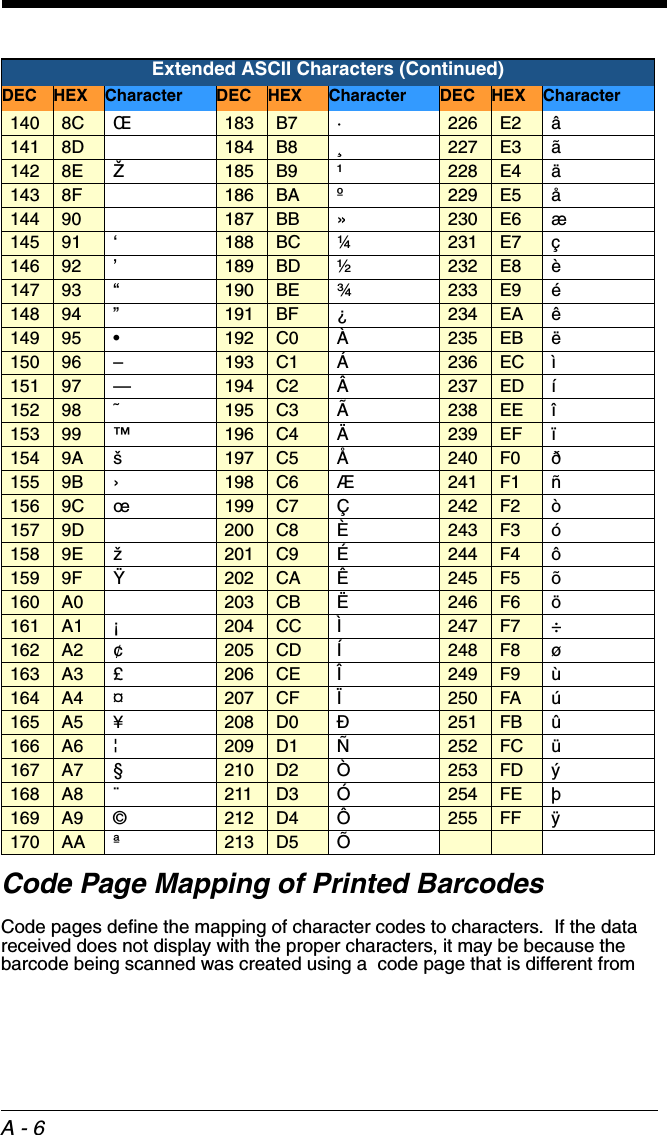
![A - 540 28 (72 48 H104 68 h41 29 )73 49 I105 69 i42 2A *74 4A J106 6A j43 2B +75 4B K107 6B k44 2C ,76 4C L108 6C l45 2D -77 4D M109 6D m46 2E .78 4E N110 6E n47 2F /79 4F O111 6F o48 30 080 50 P112 70 p49 31 181 51 Q113 71 q50 32 282 52 R114 72 r51 33 383 53 S115 73 s52 34 484 54 T116 74 t53 35 585 55 U117 75 u54 36 686 56 V118 76 v55 37 787 57 W119 77 w56 38 888 58 X120 78 x57 39 989 59 Y121 79 y58 3A :90 5A Z122 7A z59 3B ;91 5B [123 7B {60 3C <92 5C \124 7C |61 3D =93 5D ]125 7D }62 3E >94 5E ^126 7E ~63 3F ?95 5F _127 7F <DEL>Extended ASCII CharactersDEC HEX Character DEC HEX Character DEC HEX Character128 80 €€171 AB «214 D6 Ö129 81 172 AC ¬215 D7 ×130 82 ‚173 AD 216 D8 Ø131 83 ƒ174 AE ®217 D9 Ù132 84 „175 AF ¯218 DA Ú133 85 …176 B0 °219 DB Û134 86 †177 B1 ±220 DC Ü135 87 ‡178 B2 ²221 DD Ý136 88 ˆ179 B3 ³222 DE Þ137 89 ‰180 B4 ´223 DF ß138 8A Š181 B5 µ224 E0 à139 8B ‹182 B6 ¶225 E1 áPrintable Characters (Continued)DEC HEX Character DEC HEX Character DEC HEX Character](https://usermanual.wiki/Honeywell/BT010M.User-Manual/User-Guide-1663573-Page-279.png)