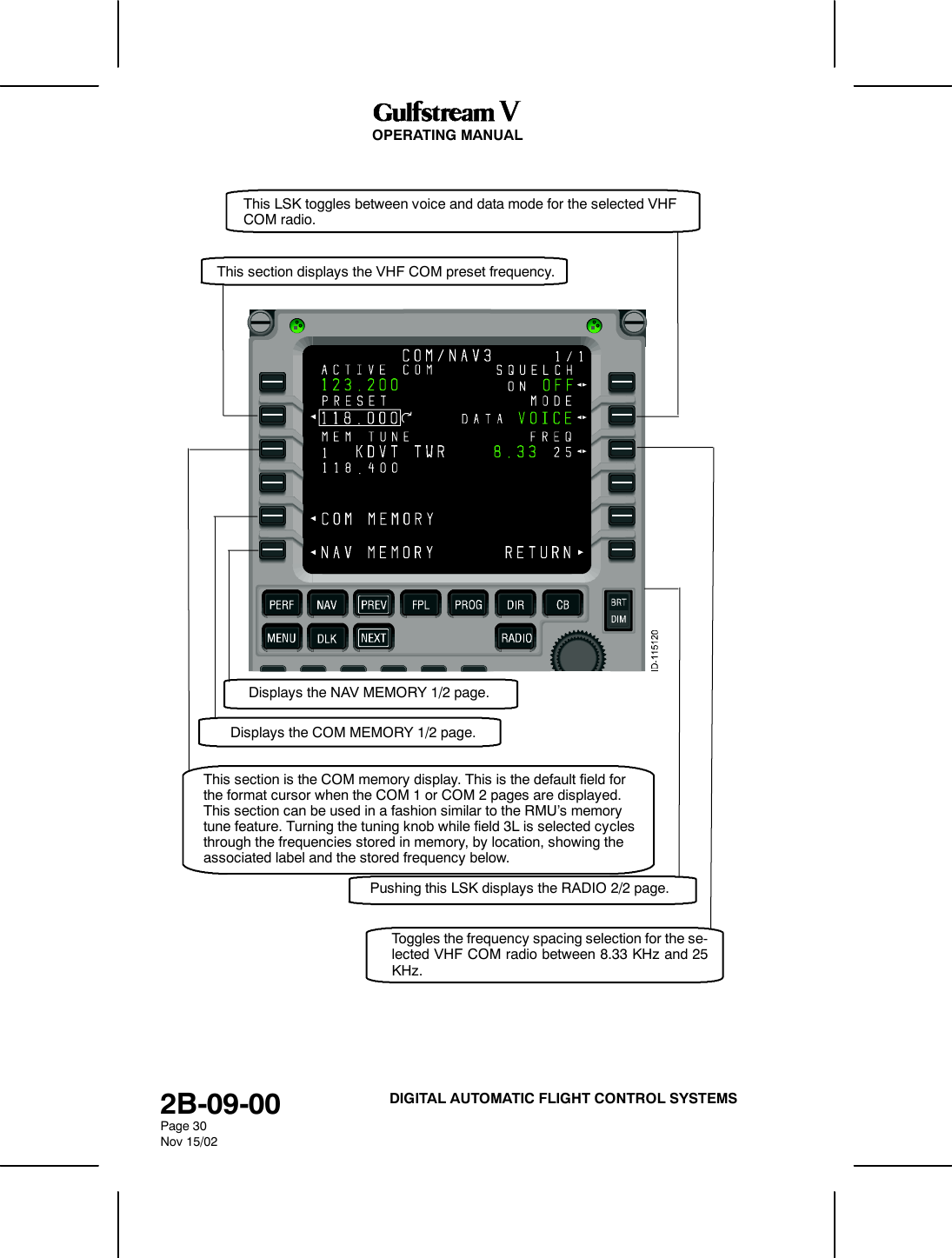
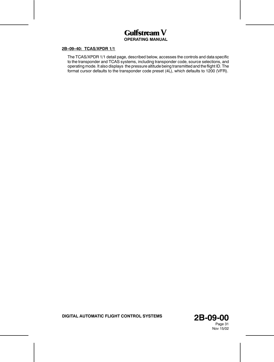
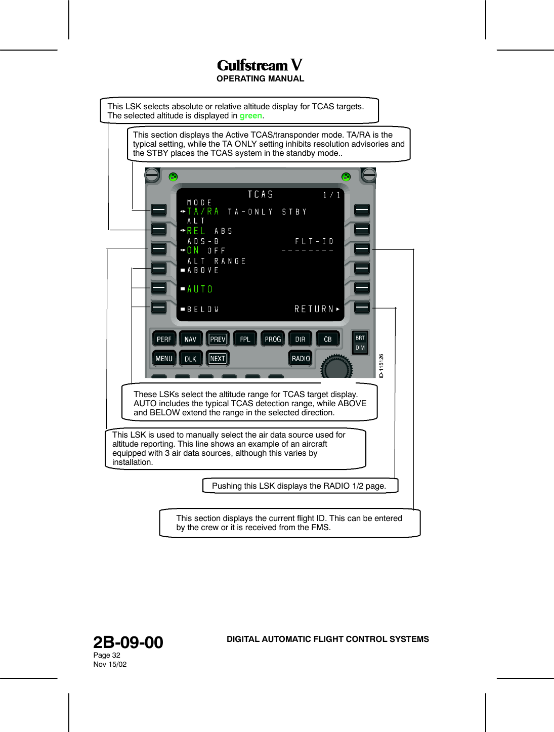
Honeywell DM855 UHF Pulsed L Band TRX User Manual Operator Manual part 1

Honeywell International Inc. UHF Pulsed L Band TRX Operator Manual part 1

Contents

Operator Manual part 1

OPERATING MANUAL2B-09-00Page 2Nov 15/02DIGITAL AUTOMATIC FLIGHT CONTROL SYSTEMS1. MCDU ControlsThe radio tuning function is operated using a subset of the controls available on the MCDU,shown in Figure 31.DNEXT and PREV Function Keys -- NEXT and PREV function keys move to adjacentpages where more than one page of the same title is usedDRADIO Function Key -- The RADIO function key activates the radio tuning functionand displays the RADIO 1/2 page,DTuning Knob -- The tuning knob is used to dial in frequencies or other numeric values.Figure 31
OPERATING MANUAL2B-09-00Page 3Nov 15/02DIGITAL AUTOMATIC FLIGHT CONTROL SYSTEMS2. Page OrganizationThe radio tuning function is accessed via the RADIO function key on the MCDU, whichdisplays the RADIO 1/2 page. All other pages are accessed from RADIO 1/2 using the lineselect keys or the NEXT and PREV function keys, shown in Figure 32.Figure 32Movement between the RADIO 1/2 and RADIO 2/2 pages is done with the NEXT and PREVfunction keys, while access to the COM DETAIL, TCAS/XPDR, and NAV DETAIL pages isvia line select keys from RADIO 1/2 and access to the HF DETAIL, MLS DETAIL, and ADFDETAIL pages are via line select keys from RADIO 2/2.
OPERATING MANUAL2B-09-00Page 4Nov 15/02DIGITAL AUTOMATIC FLIGHT CONTROL SYSTEMS3. MCDU Tuning DescriptionAll of the pages that correspond to a particular radio type (e.g., VHF communications or ADF)are arranged as shown in Figures 33, 34, and 35, and typically consist of a details page alongwith two memory pages. The details pages allow the specific features of each radio to beconfigured and provide access to the memory pages associated with each radio type.Figure 34 shows the pages associated with the VHF communications radios.Figure 33
OPERATING MANUAL2B-09-00Page 5Nov 15/02DIGITAL AUTOMATIC FLIGHT CONTROL SYSTEMSFigure 34 shows the pages associated with the VHF navigation radios.Figure 34Figure 35 shows the pages associated with the TCAS/transponder subsystemFigure 35
OPERATING MANUAL2B-09-00Page 6Nov 15/02DIGITAL AUTOMATIC FLIGHT CONTROL SYSTEMSFigure 36 shows the arrangement of pages associated with the high--frequency (HF)communications radios.Figure 36
OPERATING MANUAL2B-09-00Page 7Nov 15/02DIGITAL AUTOMATIC FLIGHT CONTROL SYSTEMSFigure 37 shows the page associated with the automatic direction finder (ADF).Figure 37
OPERATING MANUAL2B-09-00Page 8Nov 15/02DIGITAL AUTOMATIC FLIGHT CONTROL SYSTEMSFigure 38 shows the pages associated with the Microwave Landing System (MLS) receiver.Figure 38The RADIO MENU is used for manually tuning the radios. Pushing the RADIO key on theMCDU displays the RADIO MENU page 1/2.
OPERATING MANUAL2B-09-00Page 9Nov 15/02DIGITAL AUTOMATIC FLIGHT CONTROL SYSTEMS2B--09--20: BASIC OPERATIONIn keeping with the titling and numbering conventions used by MCDU functions, each MCDUpage is arranged with a centered title at the top and a page number in the upper--right corner.Page numbers are formatted as the current page number (among those with the same pagetitle), a slash ”/”, and the number of pages with the same title. For example, there are twopages entitled ”RADIO,” the first is labeled RADIO 1/2, as shown in Figure 39, and thesecond RADIO 2/2.The bottom line on each page displays the characters entered on the MCDU keypad and iscalled the scratchpad. The scratchpad is shared across all MCDU client functions, and is notunder the control of the radio tuning function.The text area adjacent to each line select key (LSK) on the MCDU is referred to as a field,and identified by the LSK it is associated with. For example, the active frequency for VHFCOM radio 1 (shown as COM1, 123.200) on the RADIO 1/2 page is in field 1L.Figure 39
OPERATING MANUAL2B-09-00Page 10Nov 15/02DIGITAL AUTOMATIC FLIGHT CONTROL SYSTEMSPushing the NEXT or PREV key when this page is displayed displays the RADIO MENUpage 2/2, shown in Figure 40.Figure 40When the scratchpad is empty, pushing a line select key either moves the format cursor tothe adjacent field, or performs the function indicated by the icon that appears near the key.The icons and their functions are described below.”Swap” frequencies. This symbol indicates that exchangesbetween the active and preset frequencies for theassociated radio can be made. This has the effect of savingthe currently active frequency in the preset memory, andtuning the radio to the frequency previously stored as thepreset.Page indicator. When this icon is displayed, pushing theadjacent LSK changes the display to another page. Thepage to be displayed is either labeled explicitly or it is a detailpage for the radio in the associated field.
OPERATING MANUAL2B-09-00Page 11Nov 15/02DIGITAL AUTOMATIC FLIGHT CONTROL SYSTEMSExclusive selection. This icon is displayed next to a list ofmutually exclusive options. Each time the adjacent LSK ispushed, the next options become selected, wrappingaround to the first when the last option is reached. Theselected value is displayed in the active color (green in thisdocument) and large font, while the other selection aredisplayed as smaller, white characters.Immediate function. This icon indicates that the functionidentified in the field will be carried out immediately when theadjacent LSK key is pushed.Copy value. This icon is used on the memory pages toindicate that the frequency highlighted by the format cursorwill be copied into the active frequency for the associatedradio.Format cursor. The cursor box highlights the value in thecurrently active field.Tuning curl. This icon indicates that the data valuehighlighted by the format cursor can be changed by turningthe MCDU tuning knob.
OPERATING MANUAL2B-09-00Page 12Nov 15/02DIGITAL AUTOMATIC FLIGHT CONTROL SYSTEMSIf LSK 2R, the second on the right hand side, shown in Figure 41, is pushed, the format cursorand tuning curl move from the 2L field (COM1) to field 2R (COM2). Likewise, pushing LSK3L moves the format cursor to the active frequency field for VHF NAV 1 radio. Oncepositioned on a field, turning the tuning knob changes the highlighted frequency.Figure 41When an icon shown above is displayed next to a line select key, the function denoted bythe icon takes precedence over moving the format cursor. For example, pushing LSK 1Lexchanges the active and preset frequencies for VHF COM1 radio, without moving theformat cursor. Consequently, it is not possible to tune the active frequency for a radio usingthe tuning knob.The exception to this rule is the case where a preset frequency is not shown for theassociated radio. This can happen when a VHF navigation radio is in DME HOLD, whichcauses the preset frequency to be removed in order to show the separately tuned DMEfrequency (refer to fields 3L and 4L in Figure 41).
OPERATING MANUAL2B-09-00Page 13Nov 15/02DIGITAL AUTOMATIC FLIGHT CONTROL SYSTEMSWhen one or more characters are present in the scratchpad, the icons adjacent to fields thataccept text entries are removed to indicate that pushing those LSKs enters the scratchpaddata into the field, as shown in Figure 42. Entering the contents of the scratchpad into a field,or manually clearing the scratchpad, restores the icons and the normal functions of the lineselect keys.Scratchpad entries can be made into any editable field at any time. Making a scratchpadentry into an active frequency field moves the previously active frequency into the preset fieldfor that radio.Figure 42
OPERATING MANUAL2B-09-00Page 14Nov 15/02DIGITAL AUTOMATIC FLIGHT CONTROL SYSTEMS2B--09--30: DETAILED PAGE DESCRIPTIONS1. RADIO 1/2RADIO 1/2, described below, displays the following radio dataDVHF COM1 and COM2 radiosDVHF NAV1 and NAV2 radiosDThe currently selected TCAS/transponder mode,DThe aircraft ID (if available)DThe current transponder code and statusAccess to RADIO 2/2 is via the NEXT or PREV function keys.
OPERATING MANUAL2B-09-00Page 15Nov 15/02DIGITAL AUTOMATIC FLIGHT CONTROL SYSTEMSVHF COM 1 active frequency. Pushing LSK 1L exchanges the active andpreset frequencies for VHF COM 1. A scratchpad entry into the field replacesthe preset frequency with the previously active frequency. The MICSTK is anexample of an alert that is displayed on the radio tuning pages.This section is the VHF COM 2 active frequency. Pushing LSK 1Rexchanges the active and preset frequencies for VHF COM 2. Ascratchpad entry into the field replaces the preset frequency with thepreviously active frequency.VHF COM 1 preset frequency. This is the default field for the formatcursor when the RADIO function key is pushed. Pushing LSK 2L whenthe format cursor is already in the field displays the COM 1 page.This section is the VHF COM 2 preset frequency. Pushing LSK 2R whenthe format cursor is already in the field displays the COM 2 page.
OPERATING MANUAL2B-09-00Page 16Nov 15/02DIGITAL AUTOMATIC FLIGHT CONTROL SYSTEMSVHF NAV 1 active frequency. When DME HOLD for NAV 1 is OFF, pushingLSK 3L exchanges the active and preset frequencies for VHF NAV 1. WhenDME HOLD for NAV 1 is ON, pushing LSK 3L moves the format cursor tofield 3L or displays the NAV 1 page if the cursor is already in the field. Ascratchpad entry into 3L replaces the preset frequency with the previousactive frequency.This section is the VHF NAV 2 active frequency. Pushing LSK 3R when DMEHOLD for NAV 2 is OFF, exchanges the active and preset frequencies for VHFNAV 2. Pushing LSK 3R when DME HOLD for NAV 2 is ON moves the formatcursor to field 3R or displays the NAV 2 page if the cursor was already in the field.A scratchpad entry into 3R replaces the preset frequency with the previous activefrequency.
OPERATING MANUAL2B-09-00Page 17Nov 15/02DIGITAL AUTOMATIC FLIGHT CONTROL SYSTEMSWhen DME HOLD for NAV 1 is OFF, this section displays the VHF NAV 1 presetfrequency. When DME HOLD is ON, this section displays the active DMEfrequency for NAV 1. The format cursor can be used in field 4L in either case. Ifthe LSK 4L is pushed when the format cursor is in the field, the NAV 1 page isdisplayed. The DME H PXR waypoint--name line is displayed to draw the crew’sattention to the separate tuning of the DME receiver.When DME HOLD for NAV 2 is OFF, the VHF NAV 2 preset frequency isdisplayed. When DME HOLD is ON, the active DME frequency for NAV 2is displayed. The format cursor is allowed in field 4R in either case.Pushing LSK 4R when the format cursor is in the field displays the NAV 2page.This section displays TCAS/XPDR 1/1This section is the Active TCAS/XPDR mode. Pushing LSK 6L togglesbetween standby (STBY) and the active TCAS/XPDR mode selectedon TCAS/XPDR 1/1.This section displays the Active transponder code and reply indicator. Theheader for field 5R shows the flight ID, if is is available or was entered bythe crew. The reply indicator (FFFF) lights when the transponder is replying toa RADAR or TCAS interrogation. Pushing LSK 5R moves the format cursorto the field or displays TCAS/XPDR 1/1 if the cursor is already in the field.Commands the transponder to transmit ident.
OPERATING MANUAL2B-09-00Page 18Nov 15/02DIGITAL AUTOMATIC FLIGHT CONTROL SYSTEMS2. RADIO 2/2RADIO 2/2, described below, displays the following radio data:DHF1 and HF2 radiosDADF1 and ADF2 radiosDOptionally installed:-COM Radio-NAV Radio-NAV/COM Radio-MLS.Access to RADIO 1/2 is via the NEXT or PREV function keys.
OPERATING MANUAL2B-09-00Page 19Nov 15/02DIGITAL AUTOMATIC FLIGHT CONTROL SYSTEMSThis section is the HF COM 1 active frequency. Pushing LSK 1Lexchanges the active and preset frequencies for HF COM 1. Ascratchpad entry into the field replaces the preset frequency with thepreviously active frequency.This section is the HF COM 2 active frequency. Pushing LSK 1Rexchanges the active and preset frequencies for HF COM 2. Ascratchpad entry into the field replaces the preset frequency withthe previously active frequency.This section is the HF COM 1 preset frequency. It is the default fieldfor the format cursor when the RADIO 2/2 page is displayed. PushingLSK 2L when the format cursor is already in the field displays the HF1 page.This section is the ADF 1 active frequency. Pushing LSK 3Lexchanges the active and preset frequencies for the ADF. Ascratchpad entry into the field replaces the preset frequency withthe previously active frequency.This is the HF COM 2 preset frequency. Pushing LSK 2R when theformat cursor is already in the field displays the HF 2 page.This is the ADF 2 active frequency. Pushing LSK 3R exchanges theactive and preset frequencies for the ADF. A scratchpad entry intothe field replaces the preset frequency with the previously activefrequency.
OPERATING MANUAL2B-09-00Page 20Nov 15/02DIGITAL AUTOMATIC FLIGHT CONTROL SYSTEMSThis section is the ADF 1 preset frequency. Pushing LSK 4L when the formatcursor is already in the field displays the ADF 1 page.This is the ADF 2 preset frequency. Pushing LSK 4R whenthe format cursor is already in the field displays the ADF 2page.This is the Active COM 3, NAV 3, or COM/NAV 3 frequency.Pushing LSK 5L exchanges the active and preset frequenciesfor the installed radio. A scratchpad entry into the fieldreplaces the preset frequency with the previously activefrequency.This section is the COM 3, NAV 3, or COM/NAV 3 preset frequency.Pushing LSK 6L when the format cursor is already in the field displaysthe detail page for the installed radio.This section is the Active MLS channel number. Pushing LSK 5Rwhen the format cursor is already in the field displays the MLS page.This section displays the MLS glidepath angle.
OPERATING MANUAL2B-09-00Page 21Nov 15/02DIGITAL AUTOMATIC FLIGHT CONTROL SYSTEMS3. COM1 PageThe COM1 page, described below, is used to access to the controls specific to VHFcommunications radios, including squelch, operating mode, and frequency spacing. It is alsoused as a quick method for retrieving frequencies from memory. The format cursor defaultsto the memory tuning field (3L), providing quick access to stored frequencies. The page alsoprovides access to the COM memory pages.
OPERATING MANUAL2B-09-00Page 22Nov 15/02DIGITAL AUTOMATIC FLIGHT CONTROL SYSTEMSActive VHF COM frequency on the selected radio (the page title reflectswhich COM radio was selected). Pushing LSK 1L exchanges the activeand preset frequencies (when the format cursor is on field 2L), or copiesa frequency stored in memory (when the format cursor is on field 3L) forthe selected COM radio. A scratchpad entry into the field replaces thepreset frequency with the previously active frequency.This LSK toggles the squelch feature for the selected VHF COMradio.This section displays the VHF COM preset frequency.This section is the COM memory display. This is the default field forthe format cursor when the COM 1 or COM 2 pages are displayed.This section can be used in a fashion similar to the RMU’s memorytune feature. Turning the tuning knob while field 3L is selected cyclesthrough the frequencies stored in memory, by location, showing theassociated label and the stored frequency below.This LSK toggles between voice and data mode for theselected VHF COM radio.Toggles the frequency spacing selection for the selected VHFCOM radio between 8.33 KHz and 25 KHz.Pushing this LSK displays the RADIO 1/2 page.Displays the COM MEMORY 1/2 page.
OPERATING MANUAL2B-09-00Page 23Nov 15/02DIGITAL AUTOMATIC FLIGHT CONTROL SYSTEMS4. COM Memory 1/2 Page‘The radio tuning function supports 12 memories per radio type (i.e., COM, NAV, HF COM,etc.) displayed on two pages each. In addition to entering or dialing--in frequencies for eachmemory, a text label of up to eight characters can be entered for each stored frequency(except for the HF COM memory page, which does not support labels due to display arealimitations). The default label for each memory is ”MEMORY,” a dash, and the memorynumber, with the memory number always on the outboard edge of the display.Active VHF COM frequency on the selected radio (the field title reflects which COMradio was selected). Pushing LSK 1L copies the field containing the format cursorinto the active frequency and moves the previously active frequency into the presetfield (not shown on this page). A scratchpad entry into the field replaces the presetfrequency with the previously active frequency.VHF COM memories 4--6.VHF COM memories 1--3.Pushing this LSK displays COM detail page.Pushing this LSK displays the RADIO 1/2 page.Labels are entered by typing into the scratchpad and pushing the line select key adjacentto the desired frequency. If the radio tuning function determines that the entry is a validfrequency for the radio, the entry is accepted into the frequency field. If not, the entry isconsidered a label and is entered into the label field above the frequency. A label can bereplaced by making another scratchpad entry into a memory field, or by pushing the DEL key.Pushing the DEL key places the text ”DELETE” in the scratchpad and, when entered on a
OPERATING MANUAL2B-09-00Page 24Nov 15/02DIGITAL AUTOMATIC FLIGHT CONTROL SYSTEMSmemory field, deletes the associated text label, returning it to the default. If the DEL key isused on a memory where there is no user--entered label, and the frequency is deleted frommemory.Access to COM MEMORY 2/2, described below, is via the NEXT and PREV function keys.Active VHF COM frequency on the selected radio (the field title reflects whichCOM radio was selected). Pushing LSK 1L copies the field containing the formatcursor into the active frequency and moves the previously active frequency intothe preset field (not shown on this page). A scratchpad entry into the fieldreplaces the preset frequency with the previously active frequency.VHF COM memories 7--9.VHF COM memories 10--12.Pushing this LSK displays COM detail page.Pushing this LSK displays the RADIO 1/2 page.
OPERATING MANUAL2B-09-00Page 25Nov 15/02DIGITAL AUTOMATIC FLIGHT CONTROL SYSTEMS5. NAV1 PageThe NAV1 page, described below, is used to access and control VHF navigation radios, FMSautomatic tuning, and DME hold mode. The format cursor defaults to the memory tuning field(4L), providing quick access to stored frequencies. The page can also access to the NAVmemory pages.
OPERATING MANUAL2B-09-00Page 26Nov 15/02DIGITAL AUTOMATIC FLIGHT CONTROL SYSTEMSActive VHF NAV frequency on the selected radio (the page title reflectswhich NAV radio was selected). Pushing LSK 1L exchanges the activeand preset frequencies (when the format cursor is on field 2L) or copiesa frequency stored in memory (when the format cursor is on field 4L) forthe selected NAV radio. A scratchpad entry into the field replaces thepreset frequency with the previously active frequency.Pushing this LSK toggles the FMS autotune feature ON andOFF for the selected VHF NAV radio.Pushing this LSK toggles the DME hold mode ON and OFFfor the selected VHF NAV radio.Pushing this LSK displays the RADIO 1/2 page.This section is the VHF NAV preset frequency.This section is the Active DME frequency. This field is onlydisplayed when the DME hold mode is enabled, otherwise DMEtuning is slaved to the corresponding VHF NAV radio frequency.This section is the NAV memory display. This is the default field for theformat cursor when the NAV 1 or NAV 2 pages are displayed. This sectionis similar to the RMU’s memory tune feature. Turning the tuning knob whilefield 4L is selected cycles through the frequencies stored in memory bylocation, showing the associated label and the stored frequency below.Pushing this key displays the NAV MEMORY 1/2 page.
OPERATING MANUAL2B-09-00Page 27Nov 15/02DIGITAL AUTOMATIC FLIGHT CONTROL SYSTEMSAs with the other radio types, the radio tuning function supports 12 navigation radiomemories displayed on two pages. In addition to entering or dialing--in frequencies for eachmemory, a text label of up to eight characters may be entered for each stored frequency. Thedefault label for each memory is ”MEMORY,” a dash, and the memory number, with thememory number always on the outboard edge of the display, as described below.Active NAV COM frequency on the selected radio (the field title reflects whichNAV radio was selected). Pushing LSK 1L copies the field containing the formatcursor into the active frequency and moves the previously active frequency intothe preset field (not shown on this page). A scratchpad entry into the fieldreplaces the preset frequency with the previously active frequency.NAV memories 1--3.NAV memories 4--6.Pushing this LSK displays NAV detail page.Pushing this LSK displays the RADIO 1/2 page.Labels are entered by typing into the scratchpad and pushing the line select key adjacentto the desired frequency. If the radio tuning function determines that the entry is a validfrequency for the radio, the entry is accepted into the frequency field. If not, the entry isconsidered a label and is entered into the label field above the frequency. A label may bereplaced by making another scratchpad entry into a memory field, or by pushing the DEL key.Pushing the DEL key places the text ”DELETE” in the scratchpad and, when entered on amemory field, deletes the associated text label, returning it to the default. If the DEL key isused on a memory where there is no user--entered label, the frequency is deleted frommemory.
OPERATING MANUAL2B-09-00Page 28Nov 15/02DIGITAL AUTOMATIC FLIGHT CONTROL SYSTEMSAccess to the NAV MEMORY 2/2, described below, is via the NEXT and PREV functionkeys.Active VHF NAV frequency on the selected radio (the field title reflects which NAVradio was selected). Pushing LSK 1L copies the field containing the format cursorinto the active frequency and moves the previously active frequency into the presetfield (not shown on this page). A scratchpad entry into the field replaces the presetfrequency with the previously active frequency.NAV memories 10--12.NAV memories 7--9.Pushing this LSK displays NAV detail page.Pushing this LSK displays the RADIO 1/2 page.
OPERATING MANUAL2B-09-00Page 29Nov 15/02DIGITAL AUTOMATIC FLIGHT CONTROL SYSTEMS6. COM/NAV 3 PageThe COM/NAV 3 Page is selected from the radio page 2/2. Select the RADIO function buttonon the MCDU. Select the NEXT function button to get to Radio 2/2, then select the line selectL6 twice to display the page. Where’s the NAV3? This looks like a COM Page withselectable COM and NAV memoriesActive VHF COM frequency on the selected radio (the page title reflectswhich COM radio was selected). Pushing LSK 1L exchanges the activeand preset frequencies (when the format cursor is on field 2L), or copiesa frequency stored in memory (when the format cursor is on field 3L) forthe selected COM radio. A scratchpad entry into the field replaces thepreset frequency with the previously active frequency.This LSK toggles the squelch feature for the selected VHF COMradio.
OPERATING MANUAL2B-09-00Page 30Nov 15/02DIGITAL AUTOMATIC FLIGHT CONTROL SYSTEMSThis section displays the VHF COM preset frequency.This section is the COM memory display. This is the default field forthe format cursor when the COM 1 or COM 2 pages are displayed.This section can be used in a fashion similar to the RMU’s memorytune feature. Turning the tuning knob while field 3L is selected cyclesthrough the frequencies stored in memory, by location, showing theassociated label and the stored frequency below.Toggles the frequency spacing selection for the se-lected VHF COM radio between 8.33 KHz and 25KHz.Pushing this LSK displays the RADIO 2/2 page.This LSK toggles between voice and data mode for the selected VHFCOM radio.Displays the NAV MEMORY 1/2 page.Displays the COM MEMORY 1/2 page.
OPERATING MANUAL2B-09-00Page 31Nov 15/02DIGITAL AUTOMATIC FLIGHT CONTROL SYSTEMS2B--09--40: TCAS/XPDR 1/1The TCAS/XPDR 1/1 detail page, described below, accesses the controls and data specificto the transponder and TCAS systems, including transponder code, source selections, andoperating mode. It also displays the pressure altitude being transmitted and the flight ID. Theformat cursor defaults to the transponder code preset (4L), which defaults to 1200 (VFR).
OPERATING MANUAL2B-09-00Page 32Nov 15/02DIGITAL AUTOMATIC FLIGHT CONTROL SYSTEMSThis LSK selects absolute or relative altitude display for TCAS targets.The selected altitude is displayed in green.This section displays the Active TCAS/transponder mode. TA/RA is thetypical setting, while the TA ONLY setting inhibits resolution advisories andthe STBY places the TCAS system in the standby mode..This LSK is used to manually select the air data source used foraltitude reporting. This line shows an example of an aircraftequipped with 3 air data sources, although this varies byinstallation.These LSKs select the altitude range for TCAS target display.AUTO includes the typical TCAS detection range, while ABOVEand BELOW extend the range in the selected direction.Pushing this LSK displays the RADIO 1/2 page.This section displays the current flight ID. This can be enteredby the crew or it is received from the FMS.
OPERATING MANUAL2B-09-00Page 33Nov 15/02DIGITAL AUTOMATIC FLIGHT CONTROL SYSTEMS2B--09--50: HF COM 1/1The HF communications detail page, described below, is used to control HF tuning (manuallyand from memory), HF tuning mode selection, transmit power selection, squelch, and toselect the operating mode. The tuning functions work just like the VHF COM selections, buteach of the tuning modes that HF radios provide: simplex, split (duplex), emergency, and ITU(channel numbers) is also selectable on this page.The preset field (2L) is not used when the tuning mode is set to split (duplex), because thatfield is used to display and tune the active receive frequency, while 1L displays the desiredtransmit frequency.When tuning from the memory field (3L), the active tuning mode is set to match the storedfrequency when it is selected. For example, in the figure below, the active tuning mode is ITU,but the selected memory location displayed in 3L is a simplex frequency. Pushing LSK 3Lto move the format cursor to the memory field, then pushing LSK 1L to make the memoryvalue active, changes the selected tuning mode from ITU to simplex (with frequency 20950selected).This section displays and controls the Active frequency or ITU channelnumber and operating mode. Pushing LSK 1L exchanges the active andpreset frequencies (when the format cursor is on field 2L) or copies afrequency stored in memory (when the format cursor is on field 3L) for theselected HF radio. A scratchpad entry into the field replaces the presetfrequency with the previous active frequency.This section displays and controls the transmit power selection.The selected level is green.This section displays and controls the squelch level selection.The selected level is green.--
OPERATING MANUAL2B-09-00Page 34Nov 15/02DIGITAL AUTOMATIC FLIGHT CONTROL SYSTEMSThis section displays and controls HF COM preset frequency (when insimplex, emergency, or ITU tuning modes) or HF COM receive frequency(when in split tuning mode). The preset feature is not available when insplit mode.This section displays and controls the HF memory display. This is thedefault field for the format cursor when the HF 1 or HF 2 pages aredisplayed. Turning the tuning knob while field 3L is selected cycles throughthe frequencies stored in memory, by location.The receive frequency is stored for the selected memory loca-tion when the memory contains a split frequency.This section contains Active frequency mode. The LSK can be usedto select simplex, split (duplex), emergency, and ITU tuning modes.This section displays the HF MEMORY 1/2 page.This LSK is used to select the operating mode: uppersideband voice (UV), lower sideband voice (LV), amplitudemodulated (AM). upper sideband data (UD), lower sidebanddata (LD) and continuous wave (CW).Pushing this LSK displays the RADIO 1/2 page.
OPERATING MANUAL2B-09-00Page 35Nov 15/02DIGITAL AUTOMATIC FLIGHT CONTROL SYSTEMS1. HF MEMORY 1/2The HF MEMORY 1/2 and 2/2 pages, described below (HF MEMORY 1/2 only), work likethe VHF COM and VHF NAV memory pages, but have a slightly different appearance dueto the need to support two line frequency displays (for split mode tuning). As a result, spacelimitations do not allow assigning labels to HF memory locations. This should not be aproblem since HF is generally used while trans--oceanic and in remote areas where thefrequencies to be used are different for each flight.The HF memory pages each contain the active HF frequency, six stored frequencies, andcontrols for changing the tuning and operating modes for each memory.Access to HF MEMORY 2/2 is via the NEXT or PREV function keys.
OPERATING MANUAL2B-09-00Page 36Nov 15/02DIGITAL AUTOMATIC FLIGHT CONTROL SYSTEMSThis LSK displays and controls the Active HF COM frequency on theselected radio (the field title reflects which radio was selected). PushingLSK 1L copies the field containing the format cursor into the activefrequency and moves the previously active frequency into the preset field(not shown on this page). A scratchpad entry into the field replaces thepreset frequency with the previous active frequency.These areas display and control stored HF COM memories 1--3 (7--9 onHF MEMORY 2/2). When a memory field contains a split frequency pair,the first push of the associated line select key moves the format cursor tothe first frequency, the second push moves it to the second frequencyfield 3L as shown.This section contains and controls the tuning mode selectionfor the frequency highlighted by the format cursor.This section is used to select Operating mode for thefrequency highlighted by the format cursor.Tuning mode selection for the frequency highlighted by theformat cursor.Pushing this LSK displays the RADIO 2/2 page.
OPERATING MANUAL2B-09-00Page 37Nov 15/02DIGITAL AUTOMATIC FLIGHT CONTROL SYSTEMS2B--09--60: ADF 1 PAGEThe ADF page, described below, displays the active, preset, and selected memoryfrequencies for the automatic direction finders, along with controls for the active mode(antenna or ADF) and the BFO setting (ON or OFF). It is also used to the ADF memorypages.
OPERATING MANUAL2B-09-00Page 38Nov 15/02DIGITAL AUTOMATIC FLIGHT CONTROL SYSTEMSThis section displays and controls the Active ADF frequency on theselected radio (the page title reflects which ADF was selected). PushingLSK 1L exchanges the active and preset frequencies (when the formatcursor is on field 2L) or copies a frequency stored in memory (when theformat cursor is on field 3L) for the selected ADF radio. A scratchpad entryinto the field replaces the preset frequency with the previous activefrequency.This section displays the ADF preset frequency.Pushing this LSK displays the ADF MEMORY 1/2 page.This section displays and controls the ADF memory display. This isthe default field for the format cursor when the ADF X page isdisplayed. Turning the tuning knob while field 3L is selected, cyclesthrough the frequencies stored in memory by location, showing theassociated label and the stored frequency below.Pushing this LSK toggles the ADF operating mode for theselected ADF. The active mode is in green.Pushing this LSK displays the RADIO 2/2 page.

Navigation menu