Honeywell DM855 UHF Pulsed L Band TRX User Manual Operator Manual part 1
Honeywell International Inc. UHF Pulsed L Band TRX Operator Manual part 1
Contents
- 1. Operator Manual part 1
- 2. Operator Manual part 2
Operator Manual part 1
OPERATING MANUAL
2B-09-00
Page 2
Nov 15/02
DIGITAL AUTOMATIC FLIGHT CONTROL SYSTEMS
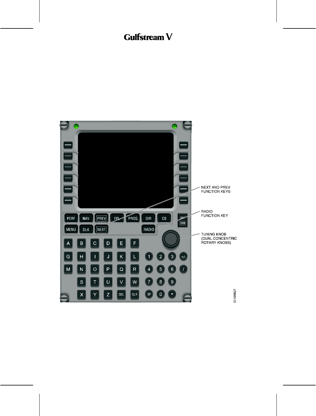
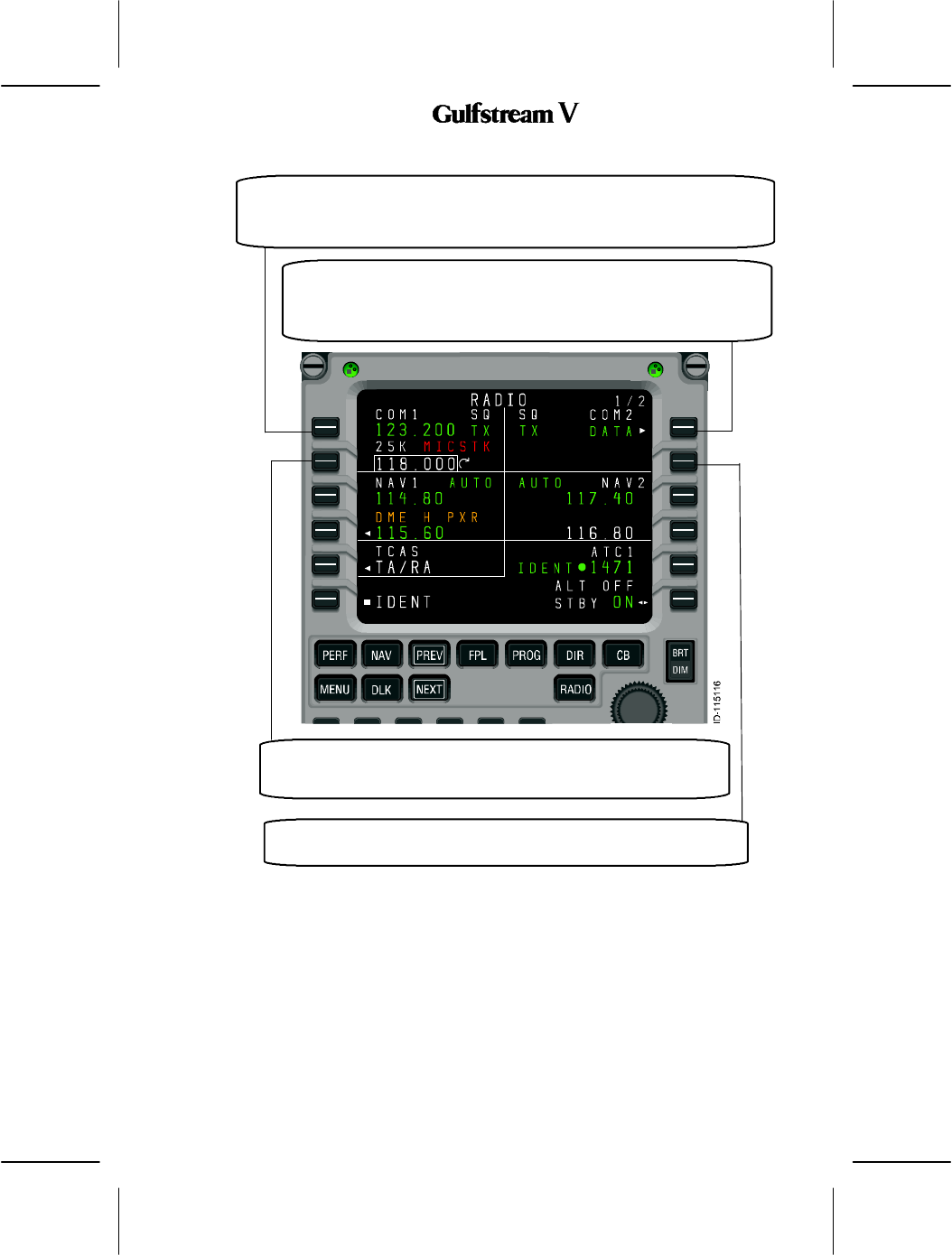
1. MCDU Controls
The radio tuning function is operated using a subset of the controls available on the MCDU,
shown in Figure 31.
DNEXT and PREV Function Keys -- NEXT and PREV function keys move to adjacent
pages where more than one page of the same title is used
DRADIO Function Key -- The RADIO function key activates the radio tuning function
and displays the RADIO 1/2 page,
DTuning Knob -- The tuning knob is used to dial in frequencies or other numeric values.
Figure 31
OPERATING MANUAL
2B-09-00
Page 3
Nov 15/02
DIGITAL AUTOMATIC FLIGHT CONTROL SYSTEMS
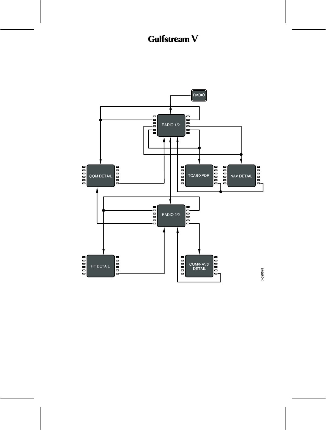
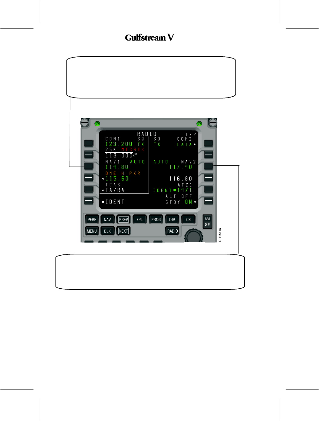
2. Page Organization
The radio tuning function is accessed via the RADIO function key on the MCDU, which
displays the RADIO 1/2 page. All other pages are accessed from RADIO 1/2 using the line
select keys or the NEXT and PREV function keys, shown in Figure 32.
Figure 32
Movement between the RADIO 1/2 and RADIO 2/2 pages is done with the NEXT and PREV
function keys, while access to the COM DETAIL, TCAS/XPDR, and NAV DETAIL pages is
via line select keys from RADIO 1/2 and access to the HF DETAIL, MLS DETAIL, and ADF
DETAIL pages are via line select keys from RADIO 2/2.
OPERATING MANUAL
2B-09-00
Page 4
Nov 15/02
DIGITAL AUTOMATIC FLIGHT CONTROL SYSTEMS
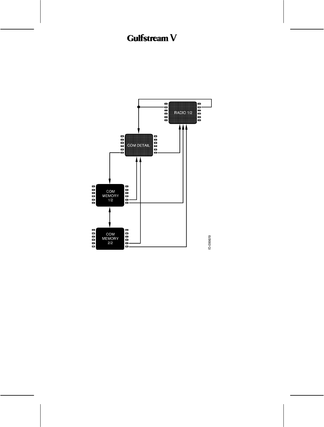
3. MCDU Tuning Description
All of the pages that correspond to a particular radio type (e.g., VHF communications or ADF)
are arranged as shown in Figures 33, 34, and 35, and typically consist of a details page along
with two memory pages. The details pages allow the specific features of each radio to be
configured and provide access to the memory pages associated with each radio type.
Figure 34 shows the pages associated with the VHF communications radios.
Figure 33
OPERATING MANUAL
2B-09-00
Page 5
Nov 15/02
DIGITAL AUTOMATIC FLIGHT CONTROL SYSTEMS
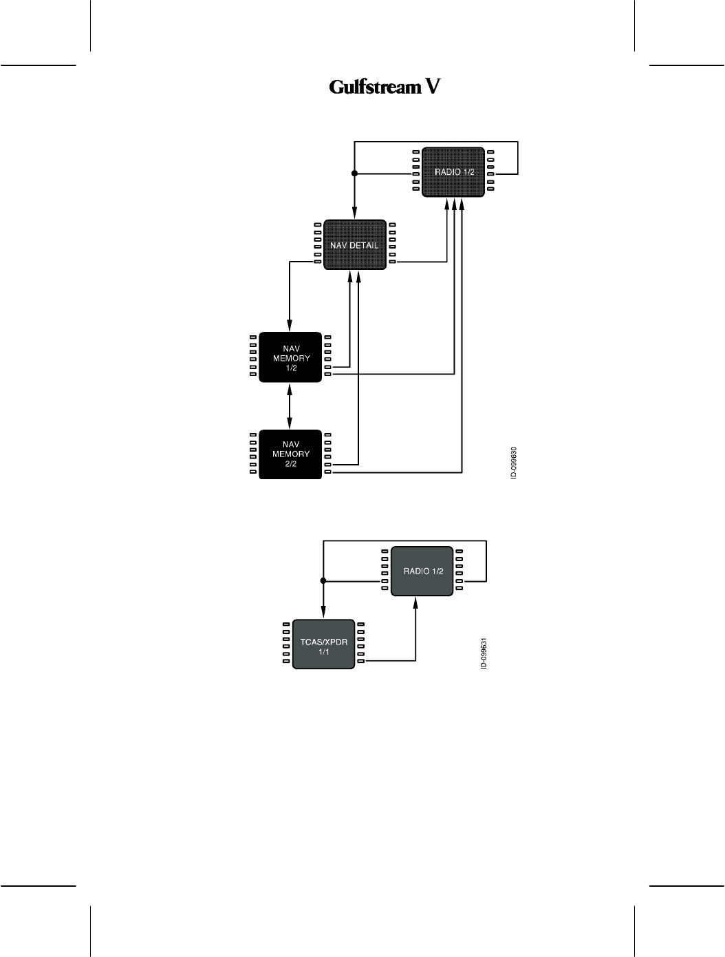
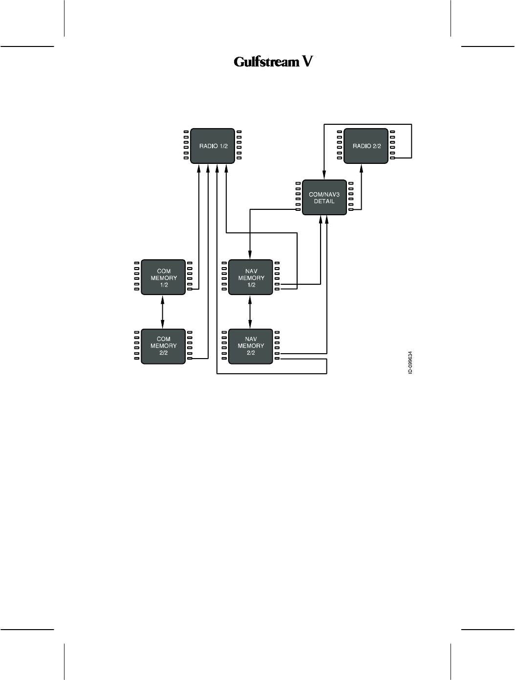
Figure 34 shows the pages associated with the VHF navigation radios.
Figure 34
Figure 35 shows the pages associated with the TCAS/transponder subsystem
Figure 35
OPERATING MANUAL
2B-09-00
Page 6
Nov 15/02
DIGITAL AUTOMATIC FLIGHT CONTROL SYSTEMS
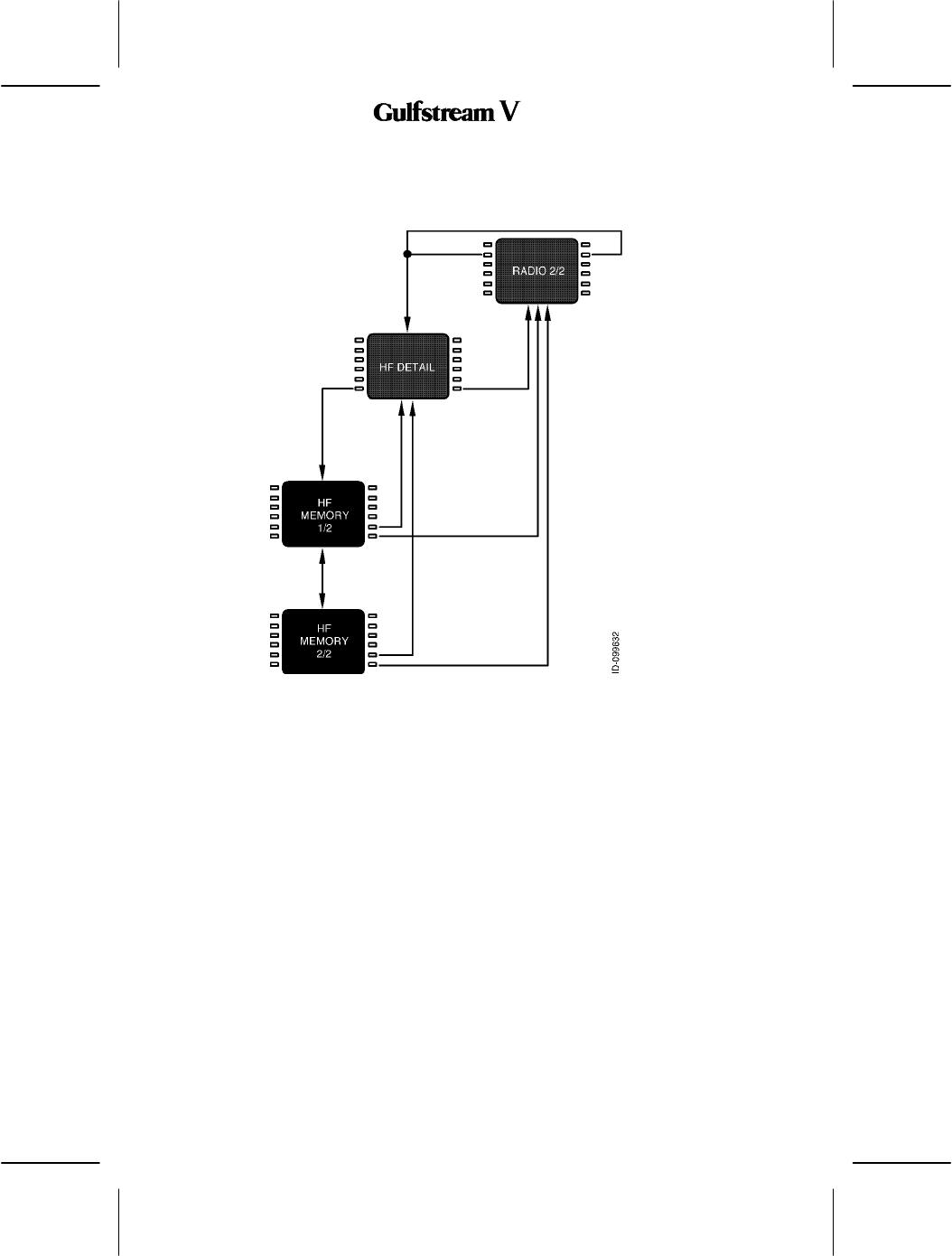
Figure 36 shows the arrangement of pages associated with the high--frequency (HF)
communications radios.
Figure 36
OPERATING MANUAL
2B-09-00
Page 7
Nov 15/02
DIGITAL AUTOMATIC FLIGHT CONTROL SYSTEMS
Figure 37 shows the page associated with the automatic direction finder (ADF).
Figure 37
OPERATING MANUAL
2B-09-00
Page 8
Nov 15/02
DIGITAL AUTOMATIC FLIGHT CONTROL SYSTEMS
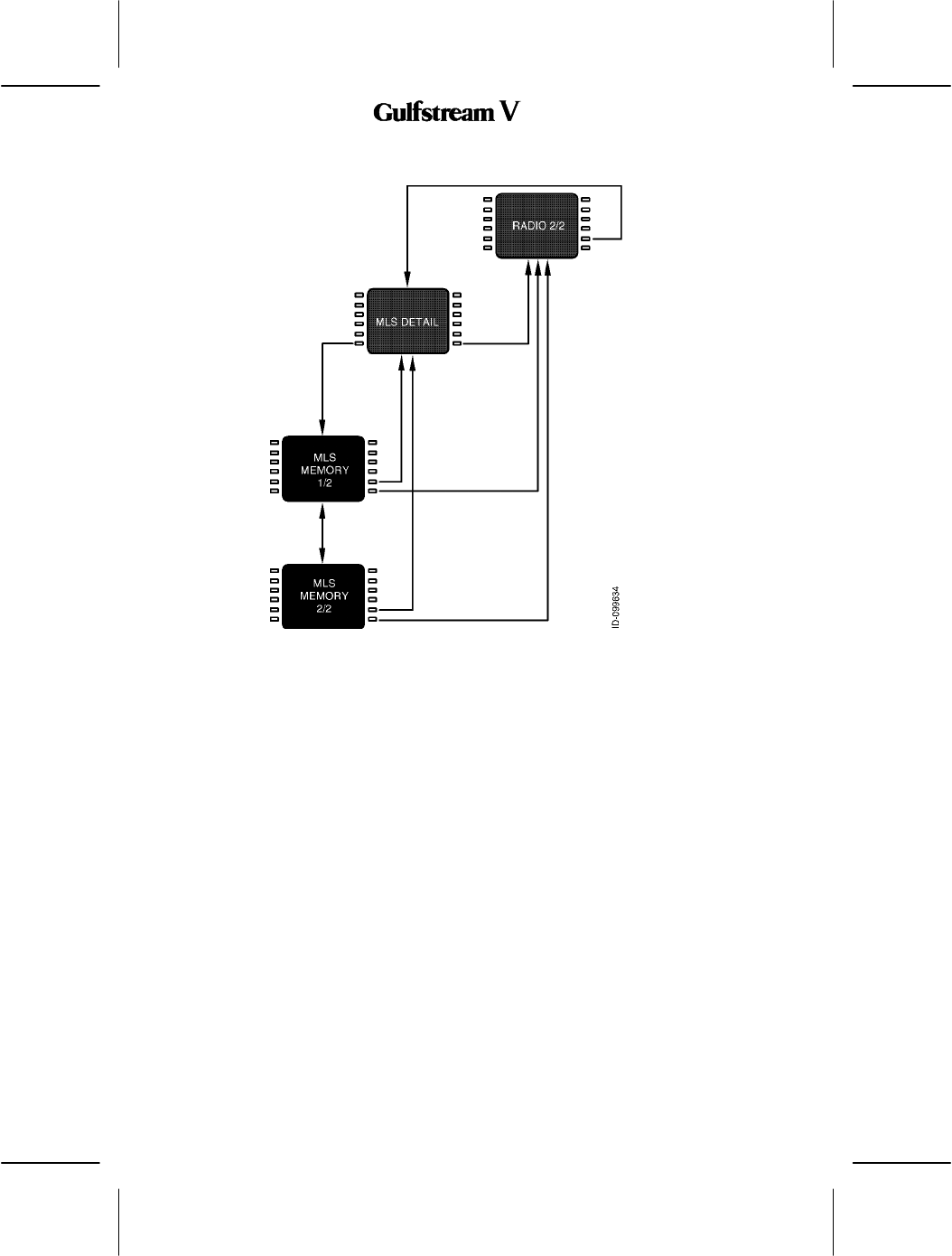
Figure 38 shows the pages associated with the Microwave Landing System (MLS) receiver.
Figure 38
The RADIO MENU is used for manually tuning the radios. Pushing the RADIO key on the
MCDU displays the RADIO MENU page 1/2.
OPERATING MANUAL
2B-09-00
Page 9
Nov 15/02
DIGITAL AUTOMATIC FLIGHT CONTROL SYSTEMS
2B--09--20: BASIC OPERATION
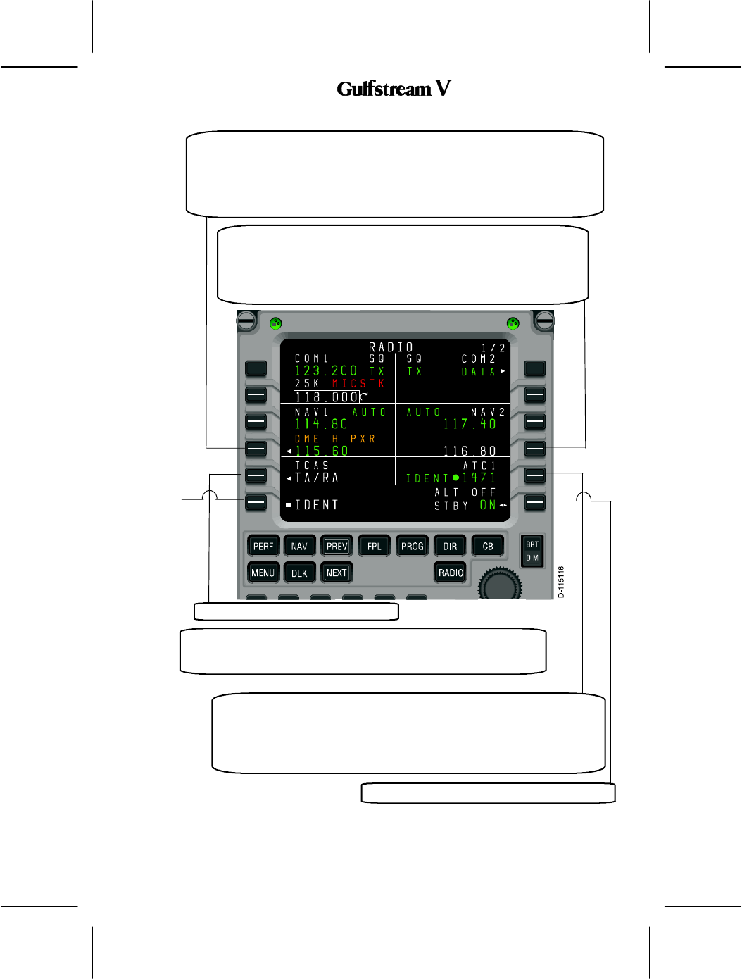
In keeping with the titling and numbering conventions used by MCDU functions, each MCDU
page is arranged with a centered title at the top and a page number in the upper--right corner.
Page numbers are formatted as the current page number (among those with the same page
title), a slash ”/”, and the number of pages with the same title. For example, there are two
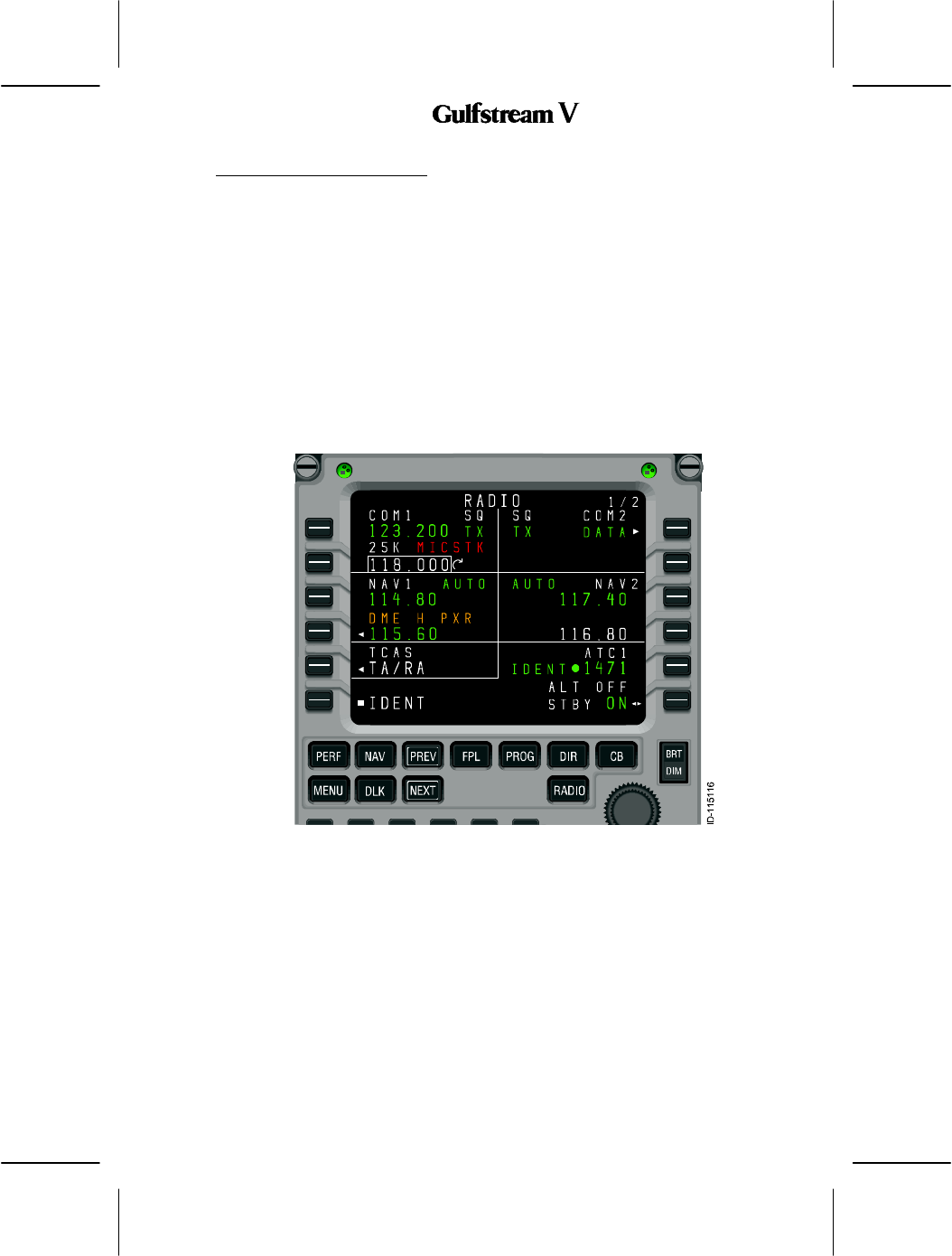
pages entitled ”RADIO,” the first is labeled RADIO 1/2, as shown in Figure 39, and the
second RADIO 2/2.
The bottom line on each page displays the characters entered on the MCDU keypad and is
called the scratchpad. The scratchpad is shared across all MCDU client functions, and is not
under the control of the radio tuning function.
The text area adjacent to each line select key (LSK) on the MCDU is referred to as a field,
and identified by the LSK it is associated with. For example, the active frequency for VHF
COM radio 1 (shown as COM1, 123.200) on the RADIO 1/2 page is in field 1L.
Figure 39
OPERATING MANUAL
2B-09-00
Page 10
Nov 15/02
DIGITAL AUTOMATIC FLIGHT CONTROL SYSTEMS
Pushing the NEXT or PREV key when this page is displayed displays the RADIO MENU
page 2/2, shown in Figure 40.
Figure 40
When the scratchpad is empty, pushing a line select key either moves the format cursor to
the adjacent field, or performs the function indicated by the icon that appears near the key.
The icons and their functions are described below.
”
Swap” frequencies. This symbol indicates that exchanges
between the active and preset frequencies for the
associated radio can be made. This has the effect of saving
the currently active frequency in the preset memory, and
tuning the radio to the frequency previously stored as the
preset.
Page indicator. When this icon is displayed, pushing the
adjacent LSK changes the display to another page. The
page to be displayed is either labeled explicitly or it is a detail
page for the radio in the associated field.
OPERATING MANUAL
2B-09-00
Page 11
Nov 15/02
DIGITAL AUTOMATIC FLIGHT CONTROL SYSTEMS
Exclusive selection. This icon is displayed next to a list of
mutually exclusive options. Each time the adjacent LSK is
pushed, the next options become selected, wrapping
around to the first when the last option is reached. The
selected value is displayed in the active color (green in this
document) and large font, while the other selection are
displayed as smaller, white characters.
I
mmediate function. This icon indicates that the function
identified in the field will be carried out immediately when the
adjacent LSK key is pushed.
Copy value. This icon is used on the memory pages to
indicate that the frequency highlighted by the format cursor
will be copied into the active frequency for the associated
radio.
Format cursor. The cursor box highlights the value in the
currently active field.
Tuning curl. This icon indicates that the data value
highlighted by the format cursor can be changed by turning
the MCDU tuning knob.
OPERATING MANUAL
2B-09-00
Page 12
Nov 15/02
DIGITAL AUTOMATIC FLIGHT CONTROL SYSTEMS
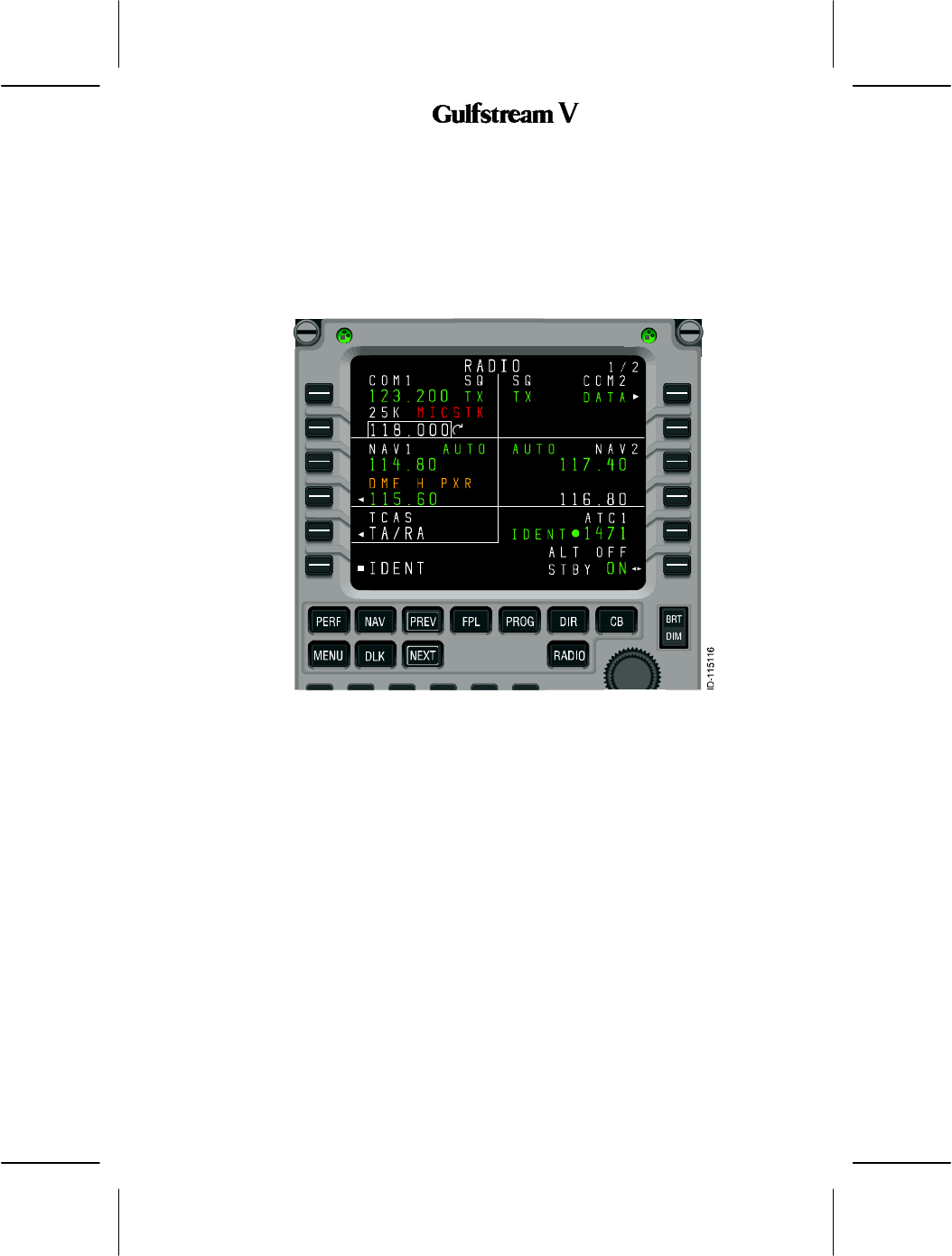
If LSK 2R, the second on the right hand side, shown in Figure 41, is pushed, the format cursor
and tuning curl move from the 2L field (COM1) to field 2R (COM2). Likewise, pushing LSK
3L moves the format cursor to the active frequency field for VHF NAV 1 radio. Once
positioned on a field, turning the tuning knob changes the highlighted frequency.
Figure 41
When an icon shown above is displayed next to a line select key, the function denoted by
the icon takes precedence over moving the format cursor. For example, pushing LSK 1L
exchanges the active and preset frequencies for VHF COM1 radio, without moving the
format cursor. Consequently, it is not possible to tune the active frequency for a radio using
the tuning knob.
The exception to this rule is the case where a preset frequency is not shown for the
associated radio. This can happen when a VHF navigation radio is in DME HOLD, which
causes the preset frequency to be removed in order to show the separately tuned DME
frequency (refer to fields 3L and 4L in Figure 41).
OPERATING MANUAL
2B-09-00
Page 13
Nov 15/02
DIGITAL AUTOMATIC FLIGHT CONTROL SYSTEMS
When one or more characters are present in the scratchpad, the icons adjacent to fields that
accept text entries are removed to indicate that pushing those LSKs enters the scratchpad
data into the field, as shown in Figure 42. Entering the contents of the scratchpad into a field,
or manually clearing the scratchpad, restores the icons and the normal functions of the line
select keys.
Scratchpad entries can be made into any editable field at any time. Making a scratchpad
entry into an active frequency field moves the previously active frequency into the preset field
for that radio.
Figure 42

OPERATING MANUAL
2B-09-00
Page 14
Nov 15/02
DIGITAL AUTOMATIC FLIGHT CONTROL SYSTEMS
2B--09--30: DETAILED PAGE DESCRIPTIONS
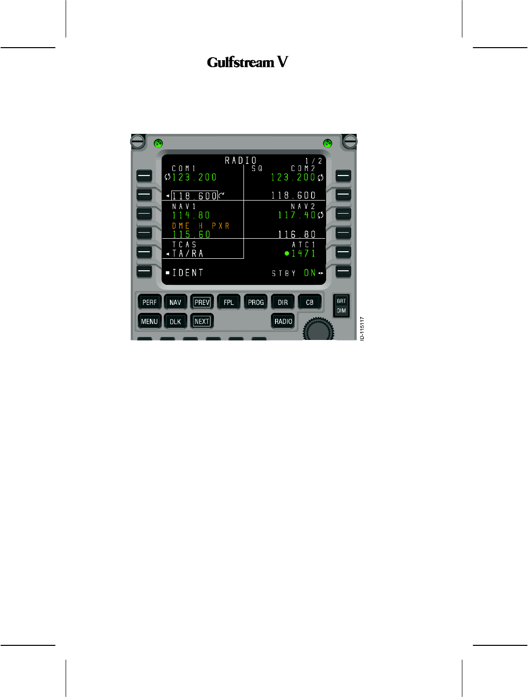
1. RADIO 1/2
RADIO 1/2, described below, displays the following radio data
DVHF COM1 and COM2 radios
DVHF NAV1 and NAV2 radios
DThe currently selected TCAS/transponder mode,
DThe aircraft ID (if available)
DThe current transponder code and status
Access to RADIO 2/2 is via the NEXT or PREV function keys.
OPERATING MANUAL
2B-09-00
Page 15
Nov 15/02
DIGITAL AUTOMATIC FLIGHT CONTROL SYSTEMS
VHF COM 1 active frequency. Pushing LSK 1L exchanges the active and
preset frequencies for VHF COM 1. A scratchpad entry into the field replaces
the preset frequency with the previously active frequency. The MICSTK is an
example of an alert that is displayed on the radio tuning pages.
This section is the VHF COM 2 active frequency. Pushing LSK 1R
exchanges the active and preset frequencies for VHF COM 2. A
scratchpad entry into the field replaces the preset frequency with the
previously active frequency.
VHF COM 1 preset frequency. This is the default field for the format
cursor when the RADIO function key is pushed. Pushing LSK 2L when
the format cursor is already in the field displays the COM 1 page.
This section is the VHF COM 2 preset frequency. Pushing LSK 2R when
the format cursor is already in the field displays the COM 2 page.
OPERATING MANUAL
2B-09-00
Page 16
Nov 15/02
DIGITAL AUTOMATIC FLIGHT CONTROL SYSTEMS
VHF NAV 1 active frequency. When DME HOLD for NAV 1 is OFF, pushing
LSK 3L exchanges the active and preset frequencies for VHF NAV 1. When
DME HOLD for NAV 1 is ON, pushing LSK 3L moves the format cursor to
field 3L or displays the NAV 1 page if the cursor is already in the field. A
scratchpad entry into 3L replaces the preset frequency with the previous
active frequency.
This section is the VHF NAV 2 active frequency. Pushing LSK 3R when DME
HOLD for NAV 2 is OFF, exchanges the active and preset frequencies for VHF
NAV 2. Pushing LSK 3R when DME HOLD for NAV 2 is ON moves the format
cursor to field 3R or displays the NAV 2 page if the cursor was already in the field.
A scratchpad entry into 3R replaces the preset frequency with the previous active
frequency.
OPERATING MANUAL
2B-09-00
Page 17
Nov 15/02
DIGITAL AUTOMATIC FLIGHT CONTROL SYSTEMS
When DME HOLD for NAV 1 is OFF, this section displays the VHF NAV 1 preset
frequency. When DME HOLD is ON, this section displays the active DME
frequency for NAV 1. The format cursor can be used in field 4L in either case. If
the LSK 4L is pushed when the format cursor is in the field, the NAV 1 page is
displayed. The DME H PXR waypoint--name line is displayed to draw the crew’s
attention to the separate tuning of the DME receiver.
When DME HOLD for NAV 2 is OFF, the VHF NAV 2 preset frequency is
displayed. When DME HOLD is ON, the active DME frequency for NAV 2
is displayed. The format cursor is allowed in field 4R in either case.
Pushing LSK 4R when the format cursor is in the field displays the NAV 2
page.
This section displays TCAS/XPDR 1/1
This section is the Active TCAS/XPDR mode. Pushing LSK 6L toggles
between standby (STBY) and the active TCAS/XPDR mode selected
on TCAS/XPDR 1/1.
This section displays the Active transponder code and reply indicator. The
header for field 5R shows the flight ID, if is is available or was entered by
the crew. The reply indicator (F
FF
F) lights when the transponder is replying to
a RADAR or TCAS interrogation. Pushing LSK 5R moves the format cursor
to the field or displays TCAS/XPDR 1/1 if the cursor is already in the field.
Commands the transponder to transmit ident.
OPERATING MANUAL
2B-09-00
Page 18
Nov 15/02
DIGITAL AUTOMATIC FLIGHT CONTROL SYSTEMS
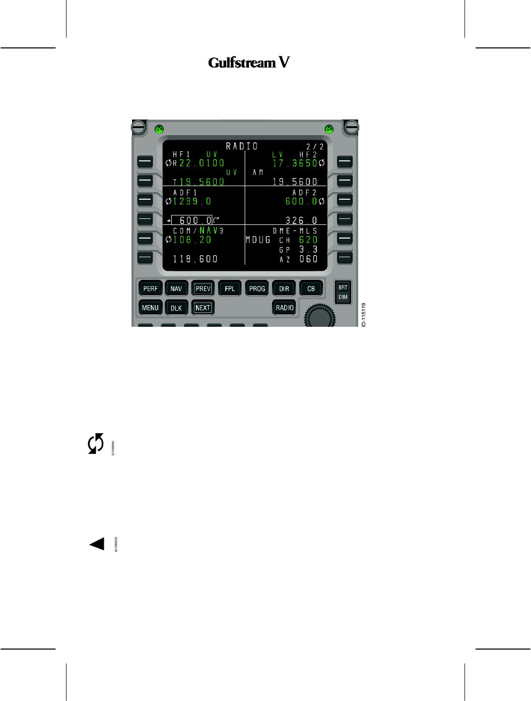
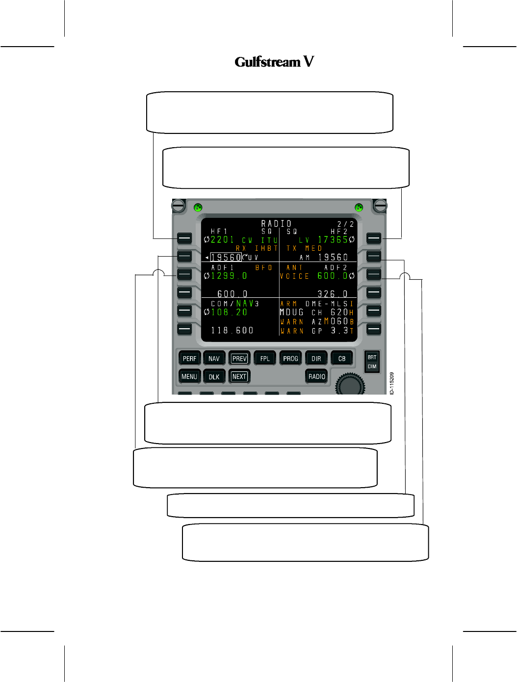
2. RADIO 2/2
RADIO 2/2, described below, displays the following radio data:
DHF1 and HF2 radios
DADF1 and ADF2 radios
DOptionally installed:
-COM Radio
-NAV Radio
-NAV/COM Radio
-MLS.
Access to RADIO 1/2 is via the NEXT or PREV function keys.
OPERATING MANUAL
2B-09-00
Page 19
Nov 15/02
DIGITAL AUTOMATIC FLIGHT CONTROL SYSTEMS
This section is the HF COM 1 active frequency. Pushing LSK 1L
exchanges the active and preset frequencies for HF COM 1. A
scratchpad entry into the field replaces the preset frequency with the
previously active frequency.
This section is the HF COM 2 active frequency. Pushing LSK 1R
exchanges the active and preset frequencies for HF COM 2. A
scratchpad entry into the field replaces the preset frequency with
the previously active frequency.
This section is the HF COM 1 preset frequency. It is the default field
for the format cursor when the RADIO 2/2 page is displayed. Pushing
LSK 2L when the format cursor is already in the field displays the HF
1 page.
This section is the ADF 1 active frequency. Pushing LSK 3L
exchanges the active and preset frequencies for the ADF. A
scratchpad entry into the field replaces the preset frequency with
the previously active frequency.
This is the HF COM 2 preset frequency. Pushing LSK 2R when the
format cursor is already in the field displays the HF 2 page.
This is the ADF 2 active frequency. Pushing LSK 3R exchanges the
active and preset frequencies for the ADF. A scratchpad entry into
the field replaces the preset frequency with the previously active
frequency.

OPERATING MANUAL
2B-09-00
Page 20
Nov 15/02
DIGITAL AUTOMATIC FLIGHT CONTROL SYSTEMS
This section is the ADF 1 preset frequency. Pushing LSK 4L when the format
cursor is already in the field displays the ADF 1 page.
This is the ADF 2 preset frequency. Pushing LSK 4R when
the format cursor is already in the field displays the ADF 2
page.
This is the Active COM 3, NAV 3, or COM/NAV 3 frequency.
Pushing LSK 5L exchanges the active and preset frequencies
for the installed radio. A scratchpad entry into the field
replaces the preset frequency with the previously active
frequency.
This section is the COM 3, NAV 3, or COM/NAV 3 preset frequency.
Pushing LSK 6L when the format cursor is already in the field displays
the detail page for the installed radio.
This section is the Active MLS channel number. Pushing LSK 5R
when the format cursor is already in the field displays the MLS page.
This section displays the MLS glidepath angle.

OPERATING MANUAL
2B-09-00
Page 21
Nov 15/02
DIGITAL AUTOMATIC FLIGHT CONTROL SYSTEMS
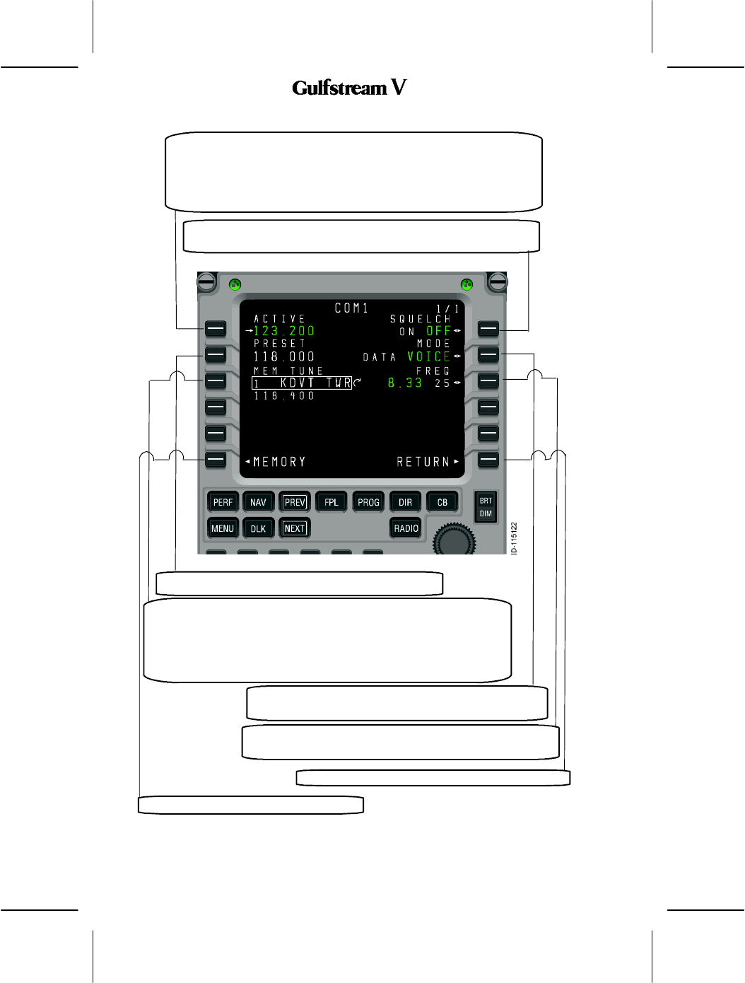
3. COM1 Page
The COM1 page, described below, is used to access to the controls specific to VHF
communications radios, including squelch, operating mode, and frequency spacing. It is also
used as a quick method for retrieving frequencies from memory. The format cursor defaults
to the memory tuning field (3L), providing quick access to stored frequencies. The page also
provides access to the COM memory pages.
OPERATING MANUAL
2B-09-00
Page 22
Nov 15/02
DIGITAL AUTOMATIC FLIGHT CONTROL SYSTEMS
Active VHF COM frequency on the selected radio (the page title reflects
which COM radio was selected). Pushing LSK 1L exchanges the active
and preset frequencies (when the format cursor is on field 2L), or copies
a frequency stored in memory (when the format cursor is on field 3L) for
the selected COM radio. A scratchpad entry into the field replaces the
preset frequency with the previously active frequency.
This LSK toggles the squelch feature for the selected VHF COM
radio.
This section displays the VHF COM preset frequency.
This section is the COM memory display. This is the default field for
the format cursor when the COM 1 or COM 2 pages are displayed.
This section can be used in a fashion similar to the RMU’s memory
tune feature. Turning the tuning knob while field 3L is selected cycles
through the frequencies stored in memory, by location, showing the
associated label and the stored frequency below.
This LSK toggles between voice and data mode for the
selected VHF COM radio.
Toggles the frequency spacing selection for the selected VHF
COM radio between 8.33 KHz and 25 KHz.
Pushing this LSK displays the RADIO 1/2 page.
Displays the COM MEMORY 1/2 page.
OPERATING MANUAL
2B-09-00
Page 23
Nov 15/02
DIGITAL AUTOMATIC FLIGHT CONTROL SYSTEMS
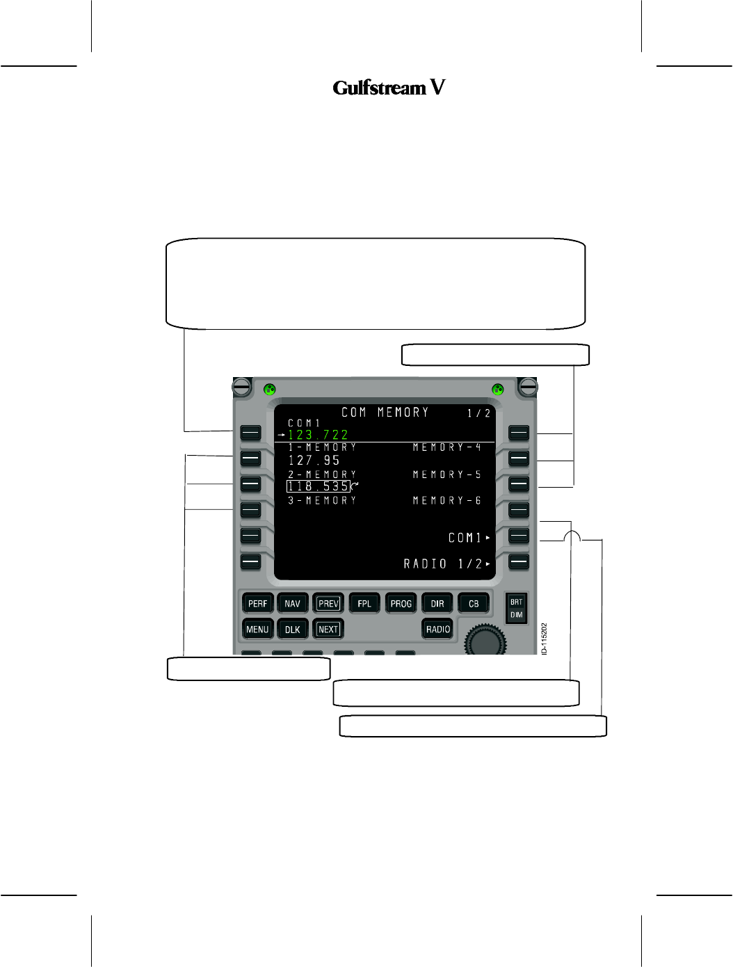
4. COM Memory 1/2 Page‘
The radio tuning function supports 12 memories per radio type (i.e., COM, NAV, HF COM,
etc.) displayed on two pages each. In addition to entering or dialing--in frequencies for each
memory, a text label of up to eight characters can be entered for each stored frequency
(except for the HF COM memory page, which does not support labels due to display area
limitations). The default label for each memory is ”MEMORY,” a dash, and the memory
number, with the memory number always on the outboard edge of the display.
Active VHF COM frequency on the selected radio (the field title reflects which COM
radio was selected). Pushing LSK 1L copies the field containing the format cursor
into the active frequency and moves the previously active frequency into the preset
field (not shown on this page). A scratchpad entry into the field replaces the preset
frequency with the previously active frequency.
VHF COM memories 4--6.
VHF COM memories 1--3.
Pushing this LSK displays COM detail page.
Pushing this LSK displays the RADIO 1/2 page.
Labels are entered by typing into the scratchpad and pushing the line select key adjacent
to the desired frequency. If the radio tuning function determines that the entry is a valid
frequency for the radio, the entry is accepted into the frequency field. If not, the entry is
considered a label and is entered into the label field above the frequency. A label can be
replaced by making another scratchpad entry into a memory field, or by pushing the DEL key.
Pushing the DEL key places the text ”DELETE” in the scratchpad and, when entered on a
OPERATING MANUAL
2B-09-00
Page 24
Nov 15/02
DIGITAL AUTOMATIC FLIGHT CONTROL SYSTEMS
memory field, deletes the associated text label, returning it to the default. If the DEL key is
used on a memory where there is no user--entered label, and the frequency is deleted from
memory.
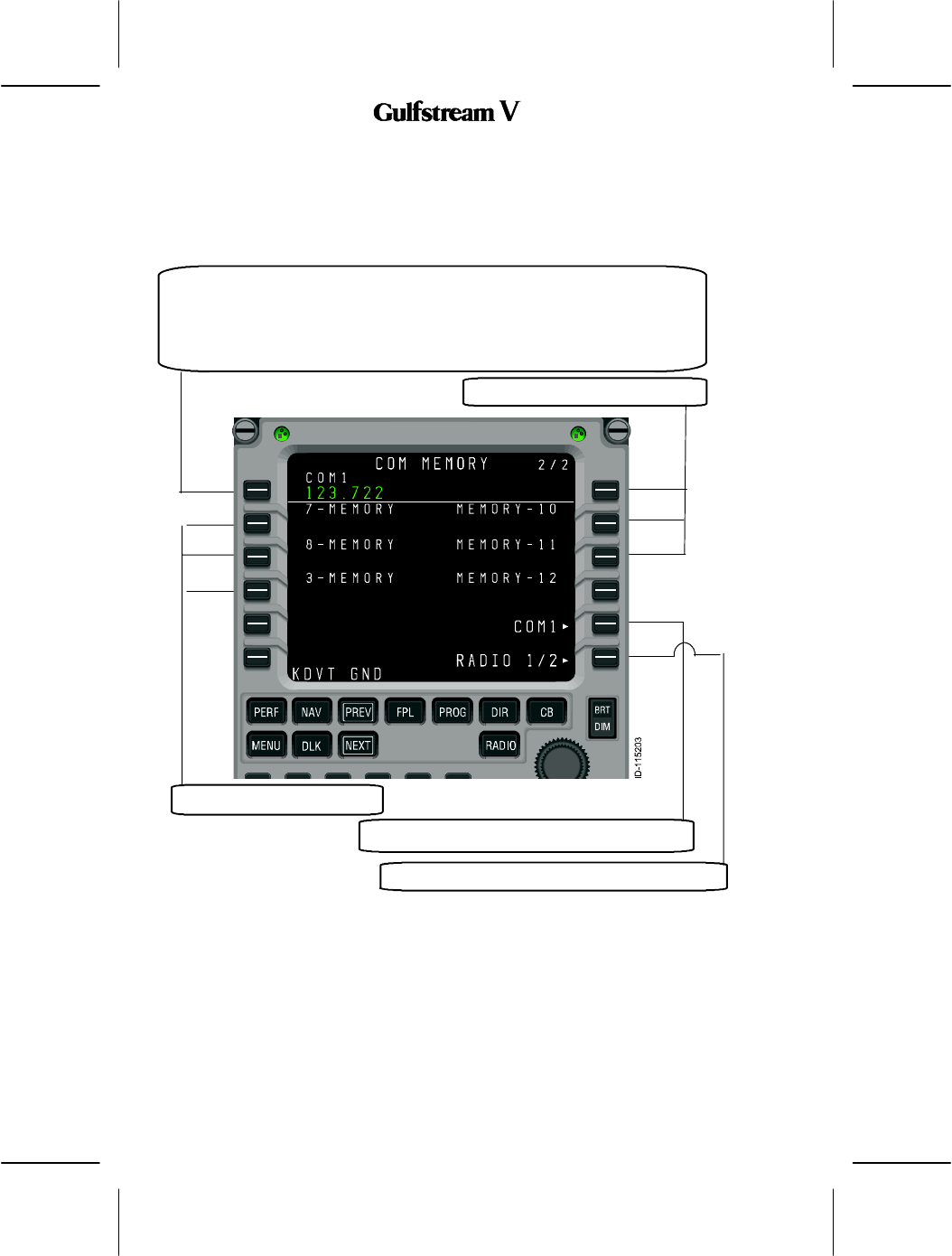
Access to COM MEMORY 2/2, described below, is via the NEXT and PREV function keys.
Active VHF COM frequency on the selected radio (the field title reflects which
COM radio was selected). Pushing LSK 1L copies the field containing the format
cursor into the active frequency and moves the previously active frequency into
the preset field (not shown on this page). A scratchpad entry into the field
replaces the preset frequency with the previously active frequency.
VHF COM memories 7--9.
VHF COM memories 10--12.
Pushing this LSK displays COM detail page.
Pushing this LSK displays the RADIO 1/2 page.

OPERATING MANUAL
2B-09-00
Page 25
Nov 15/02
DIGITAL AUTOMATIC FLIGHT CONTROL SYSTEMS
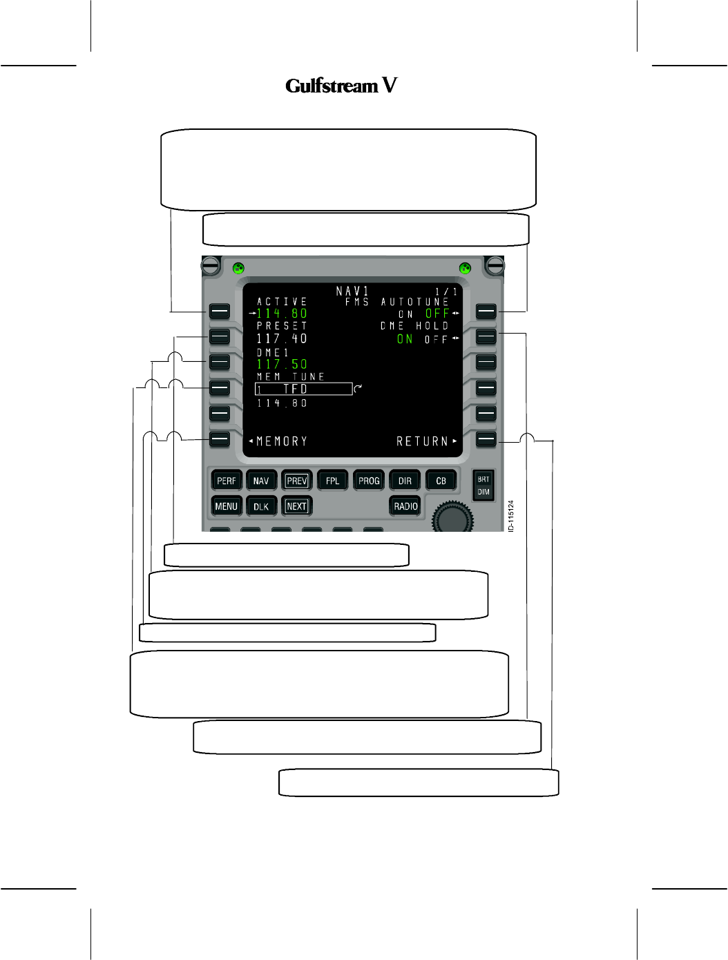
5. NAV1 Page
The NAV1 page, described below, is used to access and control VHF navigation radios, FMS
automatic tuning, and DME hold mode. The format cursor defaults to the memory tuning field
(4L), providing quick access to stored frequencies. The page can also access to the NAV
memory pages.
OPERATING MANUAL
2B-09-00
Page 26
Nov 15/02
DIGITAL AUTOMATIC FLIGHT CONTROL SYSTEMS
Active VHF NAV frequency on the selected radio (the page title reflects
which NAV radio was selected). Pushing LSK 1L exchanges the active
and preset frequencies (when the format cursor is on field 2L) or copies
a frequency stored in memory (when the format cursor is on field 4L) for
the selected NAV radio. A scratchpad entry into the field replaces the
preset frequency with the previously active frequency.
Pushing this LSK toggles the FMS autotune feature ON and
OFF for the selected VHF NAV radio.
Pushing this LSK toggles the DME hold mode ON and OFF
for the selected VHF NAV radio.
Pushing this LSK displays the RADIO 1/2 page.
This section is the VHF NAV preset frequency.
This section is the Active DME frequency. This field is only
displayed when the DME hold mode is enabled, otherwise DME
tuning is slaved to the corresponding VHF NAV radio frequency.
This section is the NAV memory display. This is the default field for the
format cursor when the NAV 1 or NAV 2 pages are displayed. This section
is similar to the RMU’s memory tune feature. Turning the tuning knob while
field 4L is selected cycles through the frequencies stored in memory by
location, showing the associated label and the stored frequency below.
Pushing this key displays the NAV MEMORY 1/2 page.
OPERATING MANUAL
2B-09-00
Page 27
Nov 15/02
DIGITAL AUTOMATIC FLIGHT CONTROL SYSTEMS
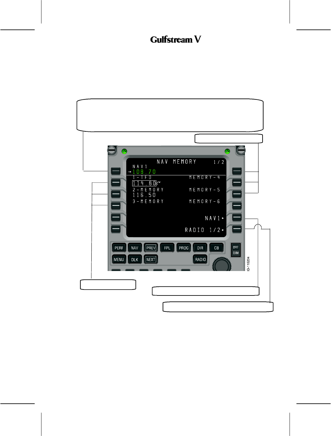
As with the other radio types, the radio tuning function supports 12 navigation radio
memories displayed on two pages. In addition to entering or dialing--in frequencies for each
memory, a text label of up to eight characters may be entered for each stored frequency. The
default label for each memory is ”MEMORY,” a dash, and the memory number, with the
memory number always on the outboard edge of the display, as described below.
Active NAV COM frequency on the selected radio (the field title reflects which
NAV radio was selected). Pushing LSK 1L copies the field containing the format
cursor into the active frequency and moves the previously active frequency into
the preset field (not shown on this page). A scratchpad entry into the field
replaces the preset frequency with the previously active frequency.
NAV memories 1--3.
NAV memories 4--6.
Pushing this LSK displays NAV detail page.
Pushing this LSK displays the RADIO 1/2 page.
Labels are entered by typing into the scratchpad and pushing the line select key adjacent
to the desired frequency. If the radio tuning function determines that the entry is a valid
frequency for the radio, the entry is accepted into the frequency field. If not, the entry is
considered a label and is entered into the label field above the frequency. A label may be
replaced by making another scratchpad entry into a memory field, or by pushing the DEL key.
Pushing the DEL key places the text ”DELETE” in the scratchpad and, when entered on a
memory field, deletes the associated text label, returning it to the default. If the DEL key is
used on a memory where there is no user--entered label, the frequency is deleted from
memory.
OPERATING MANUAL
2B-09-00
Page 28
Nov 15/02
DIGITAL AUTOMATIC FLIGHT CONTROL SYSTEMS
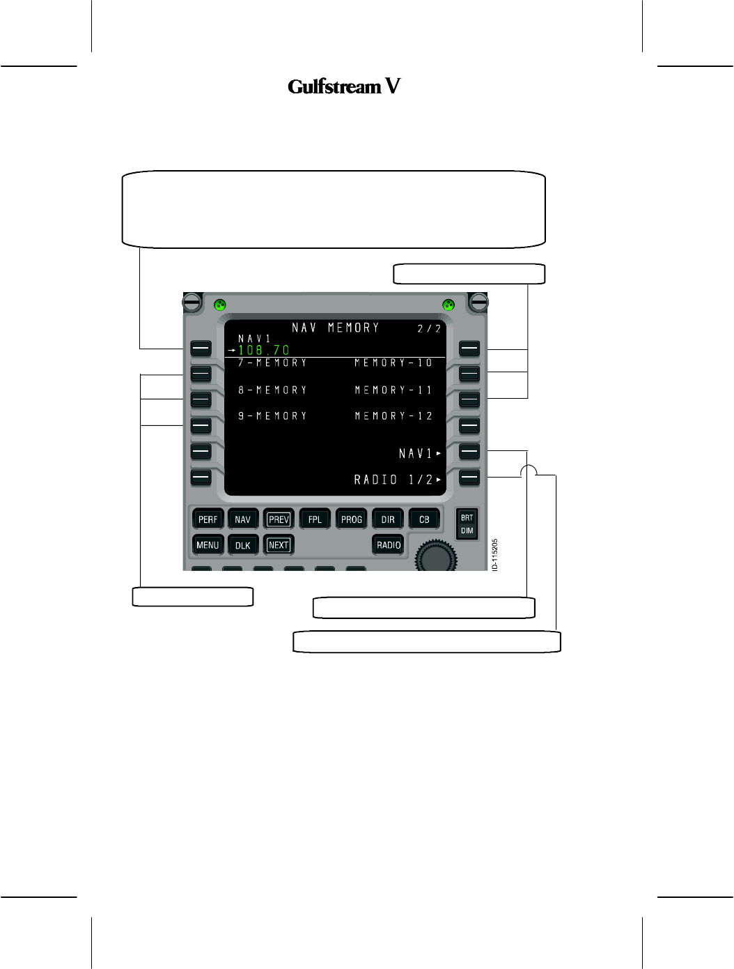
Access to the NAV MEMORY 2/2, described below, is via the NEXT and PREV function
keys.
Active VHF NAV frequency on the selected radio (the field title reflects which NAV
radio was selected). Pushing LSK 1L copies the field containing the format cursor
into the active frequency and moves the previously active frequency into the preset
field (not shown on this page). A scratchpad entry into the field replaces the preset
frequency with the previously active frequency.
NAV memories 10--12.
NAV memories 7--9.
Pushing this LSK displays NAV detail page.
Pushing this LSK displays the RADIO 1/2 page.
OPERATING MANUAL
2B-09-00
Page 29
Nov 15/02
DIGITAL AUTOMATIC FLIGHT CONTROL SYSTEMS
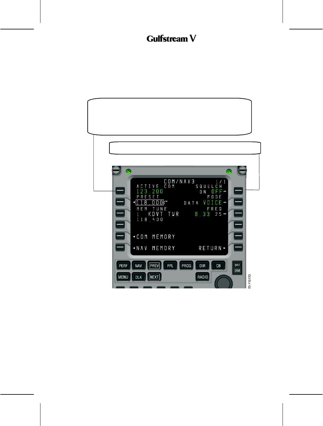
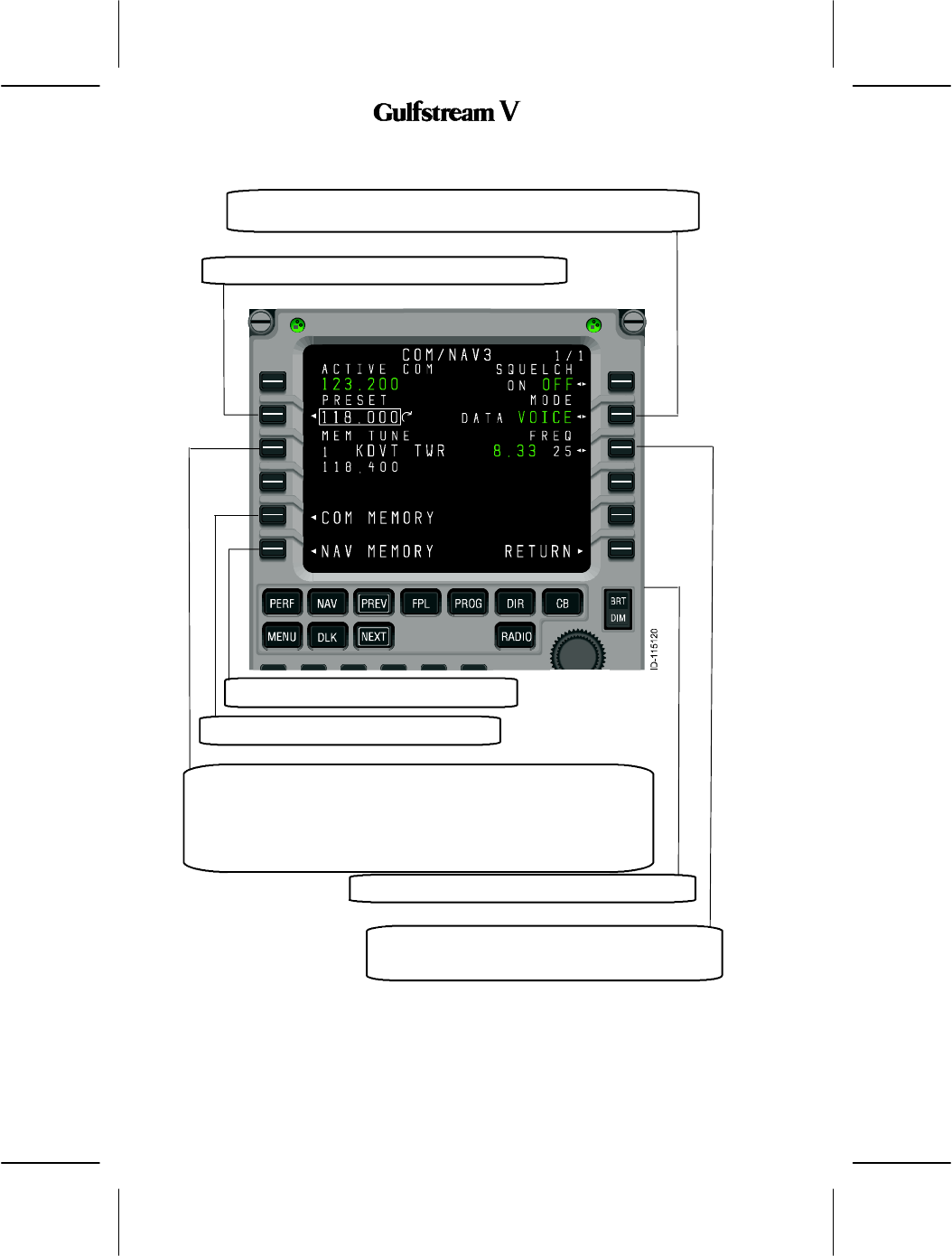
6. COM/NAV 3 Page
The COM/NAV 3 Page is selected from the radio page 2/2. Select the RADIO function button
on the MCDU. Select the NEXT function button to get to Radio 2/2, then select the line select
L6 twice to display the page. Where’s the NAV3? This looks like a COM Page with
selectable COM and NAV memories
Active VHF COM frequency on the selected radio (the page title reflects
which COM radio was selected). Pushing LSK 1L exchanges the active
and preset frequencies (when the format cursor is on field 2L), or copies
a frequency stored in memory (when the format cursor is on field 3L) for
the selected COM radio. A scratchpad entry into the field replaces the
preset frequency with the previously active frequency.
This LSK toggles the squelch feature for the selected VHF COM
radio.
OPERATING MANUAL
2B-09-00
Page 30
Nov 15/02
DIGITAL AUTOMATIC FLIGHT CONTROL SYSTEMS
This section displays the VHF COM preset frequency.
This section is the COM memory display. This is the default field for
the format cursor when the COM 1 or COM 2 pages are displayed.
This section can be used in a fashion similar to the RMU’s memory
tune feature. Turning the tuning knob while field 3L is selected cycles
through the frequencies stored in memory, by location, showing the
associated label and the stored frequency below.
Toggles the frequency spacing selection for the se-
lected VHF COM radio between 8.33 KHz and 25
KHz.
Pushing this LSK displays the RADIO 2/2 page.
This LSK toggles between voice and data mode for the selected VHF
COM radio.
Displays the NAV MEMORY 1/2 page.
Displays the COM MEMORY 1/2 page.
OPERATING MANUAL
2B-09-00
Page 31
Nov 15/02
DIGITAL AUTOMATIC FLIGHT CONTROL SYSTEMS
2B--09--40: TCAS/XPDR 1/1
The TCAS/XPDR 1/1 detail page, described below, accesses the controls and data specific
to the transponder and TCAS systems, including transponder code, source selections, and
operating mode. It also displays the pressure altitude being transmitted and the flight ID. The
format cursor defaults to the transponder code preset (4L), which defaults to 1200 (VFR).
OPERATING MANUAL
2B-09-00
Page 32
Nov 15/02
DIGITAL AUTOMATIC FLIGHT CONTROL SYSTEMS
This LSK selects absolute or relative altitude display for TCAS targets.
The selected altitude is displayed in green.
This section displays the Active TCAS/transponder mode. TA/RA is the
typical setting, while the TA ONLY setting inhibits resolution advisories and
the STBY places the TCAS system in the standby mode..
This LSK is used to manually select the air data source used for
altitude reporting. This line shows an example of an aircraft
equipped with 3 air data sources, although this varies by
installation.
These LSKs select the altitude range for TCAS target display.
AUTO includes the typical TCAS detection range, while ABOVE
and BELOW extend the range in the selected direction.
Pushing this LSK displays the RADIO 1/2 page.
This section displays the current flight ID. This can be entered
by the crew or it is received from the FMS.
OPERATING MANUAL
2B-09-00
Page 33
Nov 15/02
DIGITAL AUTOMATIC FLIGHT CONTROL SYSTEMS
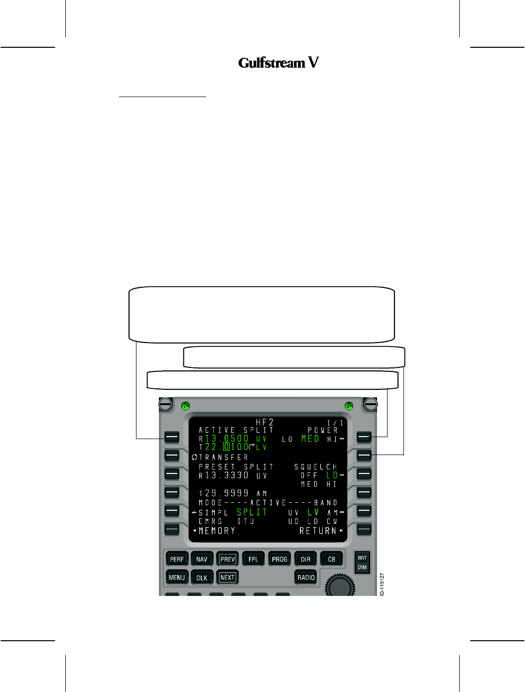
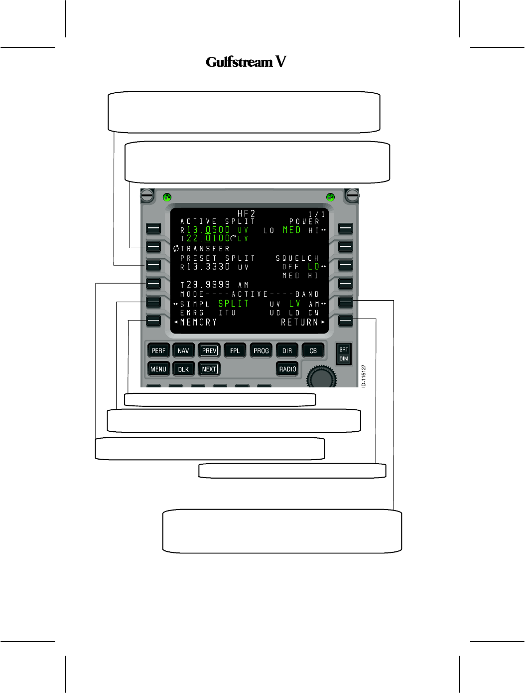
2B--09--50: HF COM 1/1
The HF communications detail page, described below, is used to control HF tuning (manually
and from memory), HF tuning mode selection, transmit power selection, squelch, and to
select the operating mode. The tuning functions work just like the VHF COM selections, but
each of the tuning modes that HF radios provide: simplex, split (duplex), emergency, and ITU
(channel numbers) is also selectable on this page.
The preset field (2L) is not used when the tuning mode is set to split (duplex), because that
field is used to display and tune the active receive frequency, while 1L displays the desired
transmit frequency.
When tuning from the memory field (3L), the active tuning mode is set to match the stored
frequency when it is selected. For example, in the figure below, the active tuning mode is ITU,
but the selected memory location displayed in 3L is a simplex frequency. Pushing LSK 3L
to move the format cursor to the memory field, then pushing LSK 1L to make the memory
value active, changes the selected tuning mode from ITU to simplex (with frequency 20950
selected).
This section displays and controls the Active frequency or ITU channel
number and operating mode. Pushing LSK 1L exchanges the active and
preset frequencies (when the format cursor is on field 2L) or copies a
frequency stored in memory (when the format cursor is on field 3L) for the
selected HF radio. A scratchpad entry into the field replaces the preset
frequency with the previous active frequency.
This section displays and controls the transmit power selection.
The selected level is green.
This section displays and controls the squelch level selection.
The selected level is green.
--
OPERATING MANUAL
2B-09-00
Page 34
Nov 15/02
DIGITAL AUTOMATIC FLIGHT CONTROL SYSTEMS
This section displays and controls HF COM preset frequency (when in
simplex, emergency, or ITU tuning modes) or HF COM receive frequency
(when in split tuning mode). The preset feature is not available when in
split mode.
This section displays and controls the HF memory display. This is the
default field for the format cursor when the HF 1 or HF 2 pages are
displayed. Turning the tuning knob while field 3L is selected cycles through
the frequencies stored in memory, by location.
The receive frequency is stored for the selected memory loca-
tion when the memory contains a split frequency.
This section contains Active frequency mode. The LSK can be used
to select simplex, split (duplex), emergency, and ITU tuning modes.
This section displays the HF MEMORY 1/2 page.
This LSK is used to select the operating mode: upper
sideband voice (UV), lower sideband voice (LV), amplitude
modulated (AM). upper sideband data (UD), lower sideband
data (LD) and continuous wave (CW).
Pushing this LSK displays the RADIO 1/2 page.
OPERATING MANUAL
2B-09-00
Page 35
Nov 15/02
DIGITAL AUTOMATIC FLIGHT CONTROL SYSTEMS
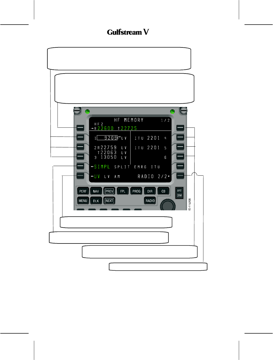
1. HF MEMORY 1/2
The HF MEMORY 1/2 and 2/2 pages, described below (HF MEMORY 1/2 only), work like
the VHF COM and VHF NAV memory pages, but have a slightly different appearance due
to the need to support two line frequency displays (for split mode tuning). As a result, space
limitations do not allow assigning labels to HF memory locations. This should not be a
problem since HF is generally used while trans--oceanic and in remote areas where the
frequencies to be used are different for each flight.
The HF memory pages each contain the active HF frequency, six stored frequencies, and
controls for changing the tuning and operating modes for each memory.
Access to HF MEMORY 2/2 is via the NEXT or PREV function keys.
OPERATING MANUAL
2B-09-00
Page 36
Nov 15/02
DIGITAL AUTOMATIC FLIGHT CONTROL SYSTEMS
This LSK displays and controls the Active HF COM frequency on the
selected radio (the field title reflects which radio was selected). Pushing
LSK 1L copies the field containing the format cursor into the active
frequency and moves the previously active frequency into the preset field
(not shown on this page). A scratchpad entry into the field replaces the
preset frequency with the previous active frequency.
These areas display and control stored HF COM memories 1--3 (7--9 on
HF MEMORY 2/2). When a memory field contains a split frequency pair,
the first push of the associated line select key moves the format cursor to
the first frequency, the second push moves it to the second frequency
field 3L as shown.
This section contains and controls the tuning mode selection
for the frequency highlighted by the format cursor.
This section is used to select Operating mode for the
frequency highlighted by the format cursor.
Tuning mode selection for the frequency highlighted by the
format cursor.
Pushing this LSK displays the RADIO 2/2 page.
OPERATING MANUAL
2B-09-00
Page 37
Nov 15/02
DIGITAL AUTOMATIC FLIGHT CONTROL SYSTEMS
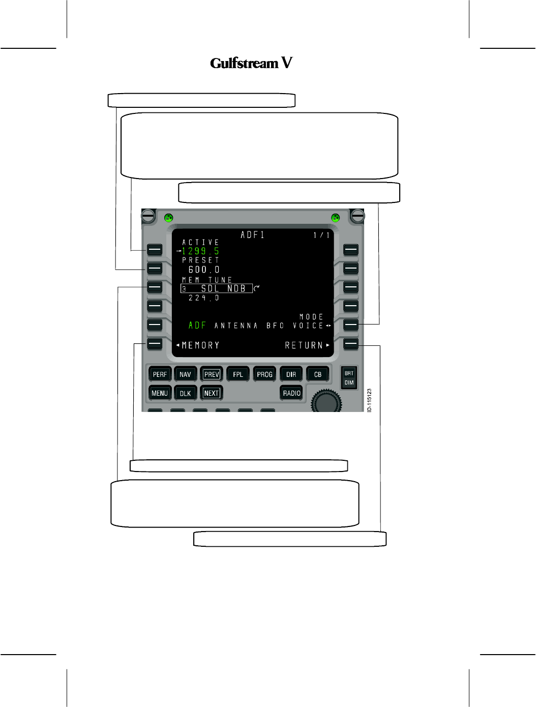
2B--09--60: ADF 1 PAGE
The ADF page, described below, displays the active, preset, and selected memory
frequencies for the automatic direction finders, along with controls for the active mode
(antenna or ADF) and the BFO setting (ON or OFF). It is also used to the ADF memory
pages.
OPERATING MANUAL
2B-09-00
Page 38
Nov 15/02
DIGITAL AUTOMATIC FLIGHT CONTROL SYSTEMS
This section displays and controls the Active ADF frequency on the
selected radio (the page title reflects which ADF was selected). Pushing
LSK 1L exchanges the active and preset frequencies (when the format
cursor is on field 2L) or copies a frequency stored in memory (when the
format cursor is on field 3L) for the selected ADF radio. A scratchpad entry
into the field replaces the preset frequency with the previous active
frequency.
This section displays the ADF preset frequency.
Pushing this LSK displays the ADF MEMORY 1/2 page.
This section displays and controls the ADF memory display. This is
the default field for the format cursor when the ADF X page is
displayed. Turning the tuning knob while field 3L is selected, cycles
through the frequencies stored in memory by location, showing the
associated label and the stored frequency below.
Pushing this LSK toggles the ADF operating mode for the
selected ADF. The active mode is in green.
Pushing this LSK displays the RADIO 2/2 page.