Honeywell DM855 UHF Pulsed L Band TRX User Manual Operator Manual part 2
Honeywell International Inc. UHF Pulsed L Band TRX Operator Manual part 2
Contents
- 1. Operator Manual part 1
- 2. Operator Manual part 2
Operator Manual part 2

OPERATING MANUAL
2B-09-00
Page 39
Nov 15/02
DIGITAL AUTOMATIC FLIGHT CONTROL SYSTEMS
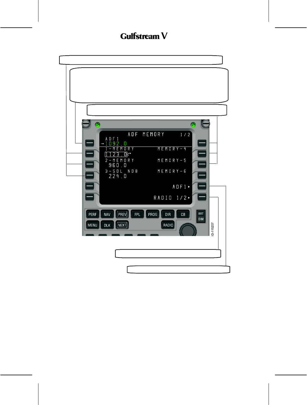
1. ADF Memory
As with the other radio types, the radio tuning function supports 12 ADF memories displayed
on two pages. In addition to entering or dialing--in frequencies for each memory, a text label
of up to 8 characters may be entered for each stored frequency. The default label for each
memory is ”MEMORY”, a dash, and the memory number, with the memory number always
on the outboard edge of the display. The ADF Memory page is described below.
Labels are entered by typing into the scratchpad and pushing the LSK adjacent to the desired
frequency. If the radio tuning function determines that the entry is a valid frequency for the
radio, the entry is accepted into the frequency field. If not, the entry is considered a label and
is entered into the label field above the frequency. A label can be replaced by making another
scratchpad entry into a memory field, or by pushing the DEL key. Pushing the DEL key
places the text ”DELETE” in the scratchpad and, when entered on a memory field, deletes
the associated text label, returning it to the default. If the DEL key is used on a memory where
there is no user--entered label, the frequency is deleted from memory.
Access to the ADF MEMORY 2/2 page is via the NEXT and PREV function keys.
OPERATING MANUAL
2B-09-00
Page 40
Nov 15/02
DIGITAL AUTOMATIC FLIGHT CONTROL SYSTEMS
This section displays and controls the Active ADF frequency on the
selected radio (the field title will reflect which radio was selected).
Pushing LSK 1L copies the field containing the format cursor into the
active frequency and moves the previously active frequency into the
preset field (not shown on this page). A scratchpad entry into the field
replaces the preset frequency with the previous active frequency.
These sections display the ADF memories 1--3 (7--9 on ADF MEMORY 2/2).
These sections display the ADF memories 4--6 (10--12 on ADF
MEMORY 2/2).
Pushing this LSK displays ADF detail page.
Pushing this LSK displays the RADIO 2/2 page.
OPERATING MANUAL
2B-09-00
Page 41
Nov 15/02
DIGITAL AUTOMATIC FLIGHT CONTROL SYSTEMS
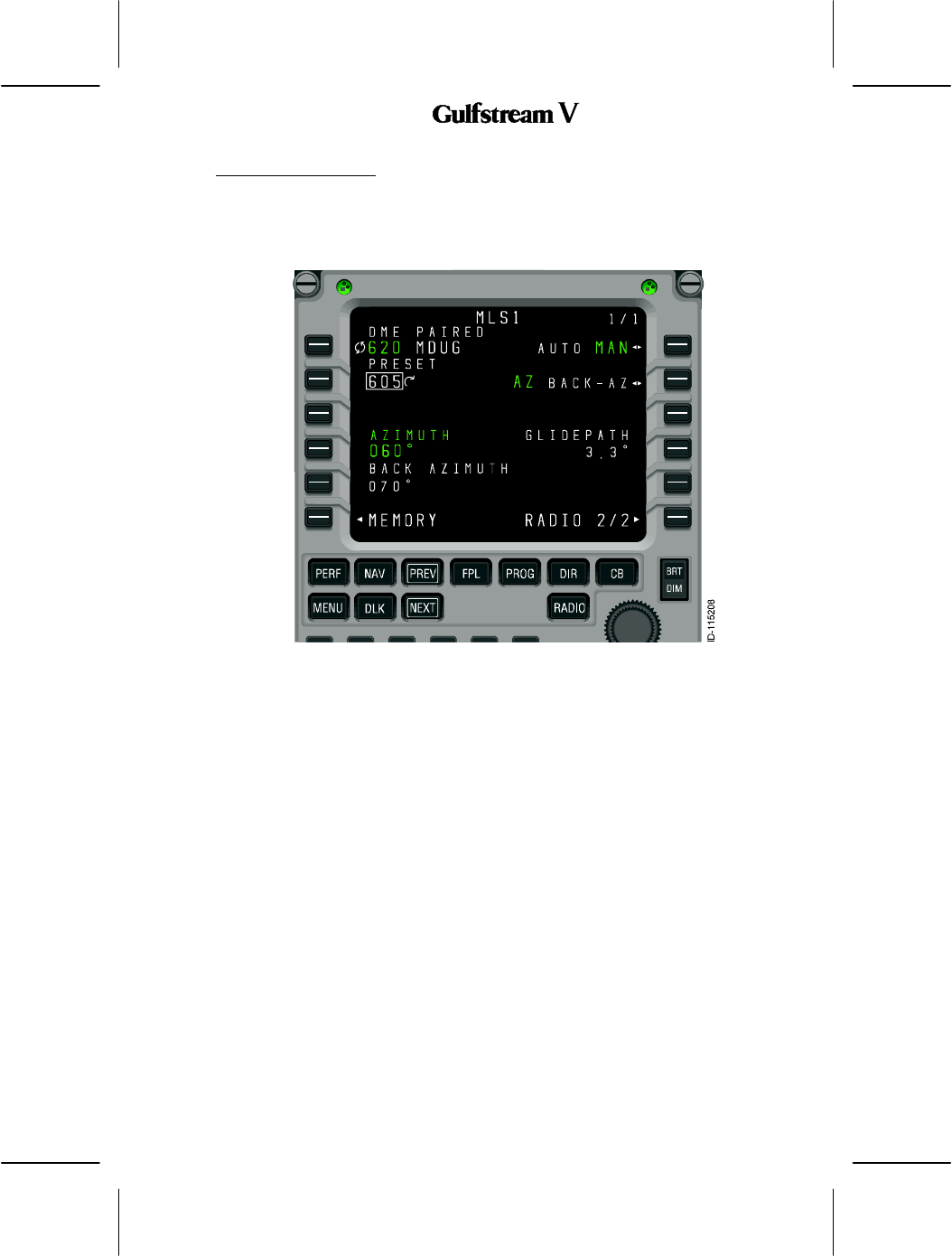
2B--09--70: MLS1 PAGE
The MLS page, shown in Figure 43, shows the currently tuned procedure and a preset,
azimuth and back--azimuth, and glidepath angle, and allows setting of the operating mode
(automatic/manual) and azimuth selection (azimuth or back--azimuth). It also provides
access to the MLS memory pages.
Figure 43
Unlike the detail pages for the other radios, the MLS page does not support the fast memory
tuning operation in field 3L.

OPERATING MANUAL
2B-09-00
Page 42
Nov 15/02
DIGITAL AUTOMATIC FLIGHT CONTROL SYSTEMS
1. MLS Memory Pages
The MLS memory pages, FINISH THIS SECTION
Figure 44
OPERATING MANUAL
2B-09-00
Page 43
Nov 15/02
DIGITAL AUTOMATIC FLIGHT CONTROL SYSTEMS
2B--09--80: RADIO INTERACTIONS
The MCDU radio tuning function communicates with the radio units using a bi--directional
protocol. The radio tuning function expects to receive an acknowledgement when the radio
is successful in completing each tuning command.
A typical interaction begins with the user entering or dialing in a new frequency for a radio.
The MCDU sends the appropriate tuning command to the specified radio and awaits
confirmation. If no confirmation is received within the timeout period, the frequency display
on the page is changed to amber and a scratchpad message is issued as shown in Figure
45).
Figure 45
The pilot can attempt to tune the radio again, in the event that the fault was transient or has
been cleared by crew action. This is also important in the event that the radio is receiving the
command and is, in fact, tuning the radio, but is unable to respond to the MCDU.
OPERATING MANUAL
2B-09-00
Page 44
Nov 15/02
DIGITAL AUTOMATIC FLIGHT CONTROL SYSTEMS
2B--09--90: ANNUNCIATION MESSAGES
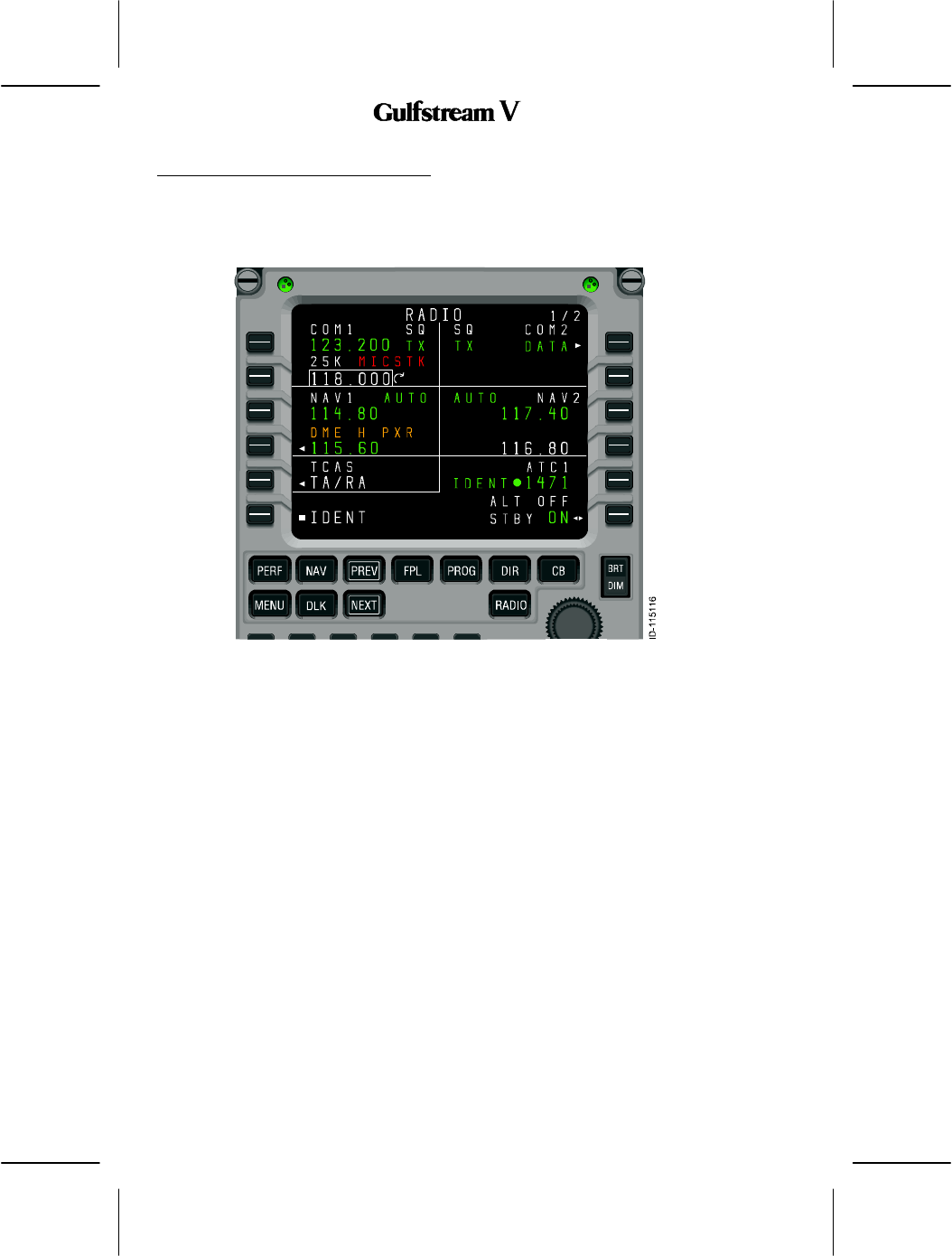
1. RADIO 1/2 Annunciations
A variety of annunciations appear on the radio tuning pages, many of which are shown in
Figure 46.
Figure 46
OPERATING MANUAL
2B-09-00
Page 45
Nov 15/02
DIGITAL AUTOMATIC FLIGHT CONTROL SYSTEMS
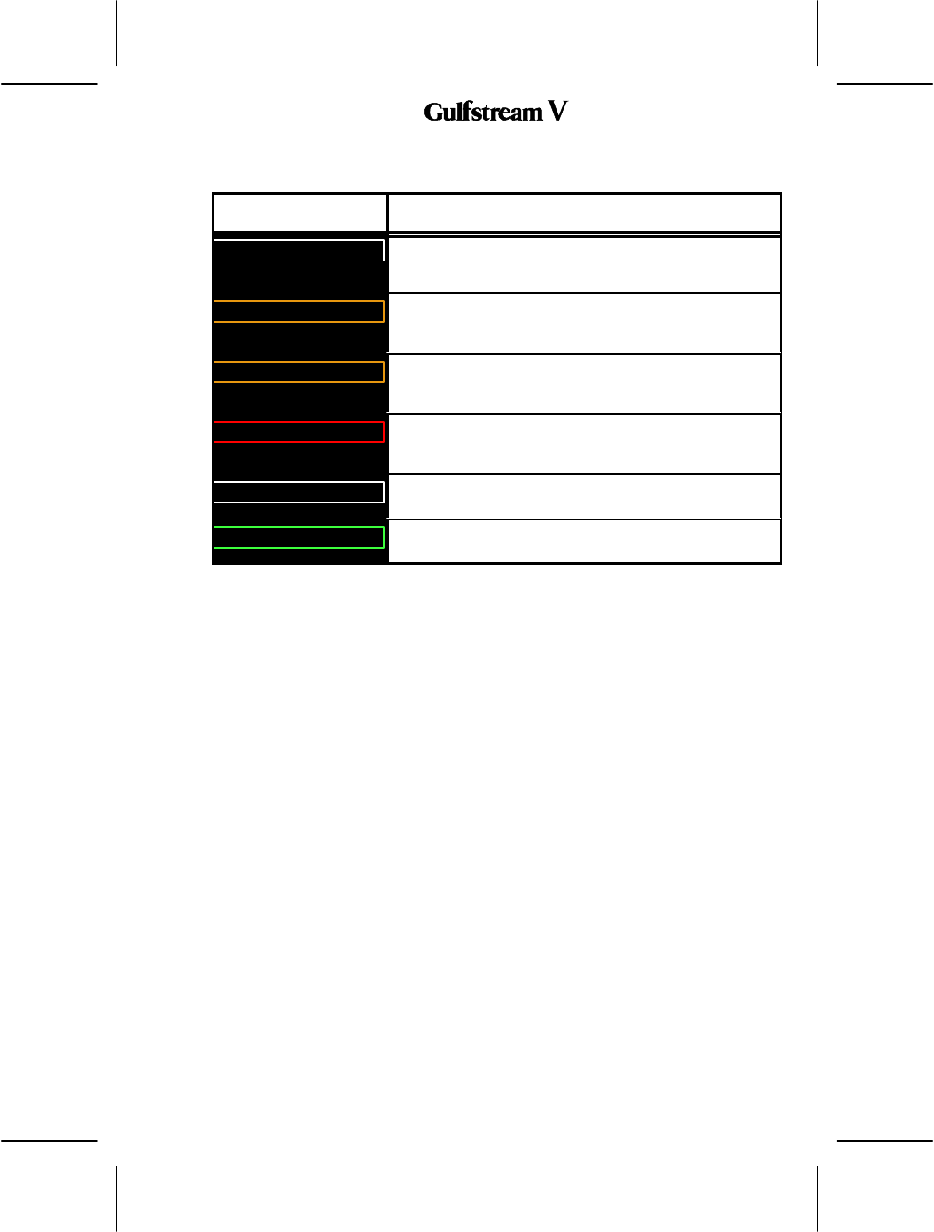
Table 33 describes the annunciators on RADIO 1/2.
Annunciator Description
25K
Indicates that the associated VHF COM radio is set to 25KHz
frequency spacing. When not present, the radio is tuning with
8.33KHz frequency spacing.
DME H xxx
This alert Indicates that the VHF navigation radio is tuning the
corresponding DME receiver independently of the primary
navigation frequency.
IHBT
This annunciator Indicates that tuning of the radio is inhibited,
usually from a remote source (such as an emergency tuning
function).
MICSTK
Indicates that the microphone button on the radio has been
down long enough that the radio has identified it as ”stuck” in the
transmit position.
SQ
This annunciator Indicates that the squelch feature for the radio
is active.
TX
This annunciator Indicates that the radio is currently
transmitting.
RADIO 1/2 Annunciator Descriptions
Table 33

OPERATING MANUAL
2B-09-00
Page 46
Nov 15/02
DIGITAL AUTOMATIC FLIGHT CONTROL SYSTEMS
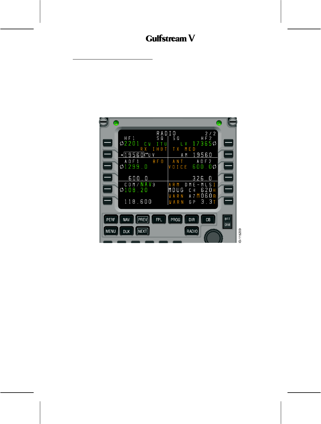
2. RADIO 2/2 Annunciations
A variety of annunciations appear on the radio tuning pages, many of which are shown in in
Figure 46.
Figure 47
OPERATING MANUAL
2B-09-00
Page 47
Nov 15/02
DIGITAL AUTOMATIC FLIGHT CONTROL SYSTEMS
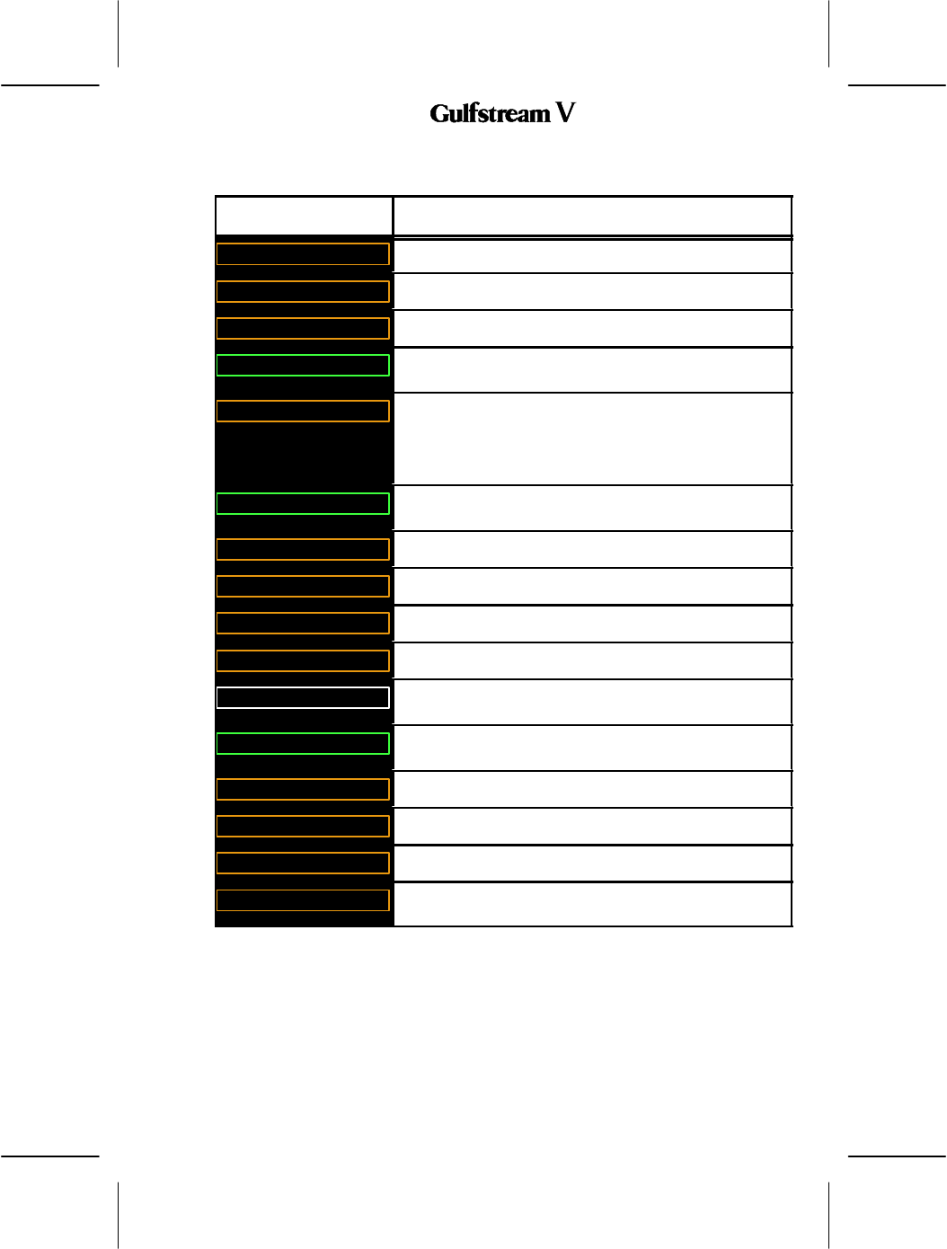
Table 34 describes the annunciators on RADIO 2/2.
Annunciator Description
ANT
The ADF radio is in antenna mode.
ARM
An MLS procedure is armed.
BFO
The ADF radio is operating in BFO mode.
CW
This annunciator Indicates that the radio is currently
transmitting.
IHBT
Indicates that tuning of the radio is inhibited, usually from a
remote source (such as an emergency tuning function). In the
case of two HF radios sharing a single antenna, transmitting
and/or receiving may be inhibited periodically when the other HF
radio has recently performed a transmit operation.
ITU
This annunciator Indicates that the radio is currently
transmitting.
LO
The radio is set to low squelch.
M
An MLS parameter has been set manually.
MED
The radio is set to medium squelch.
RX
Indicates that the radio is currently receiving.
SQ
This annunciator Indicates that the squelch feature for the radio
is active.
TX
This annunciator Indicates that the radio is currently
transmitting.
TX LO
The radio is transmitting with low power.
TX MED
The radio is transmitting with medium power.
VOICE
The ADF radio is in voice mode.
WARN
There is a problem with the azimuth, back--azimuth, or glidepath
data for the MLS procedure.
RADIO 2/2 Annunciator Descriptions
Table 34
OPERATING MANUAL
2B-09-00
Page 48
Nov 15/02
DIGITAL AUTOMATIC FLIGHT CONTROL SYSTEMS
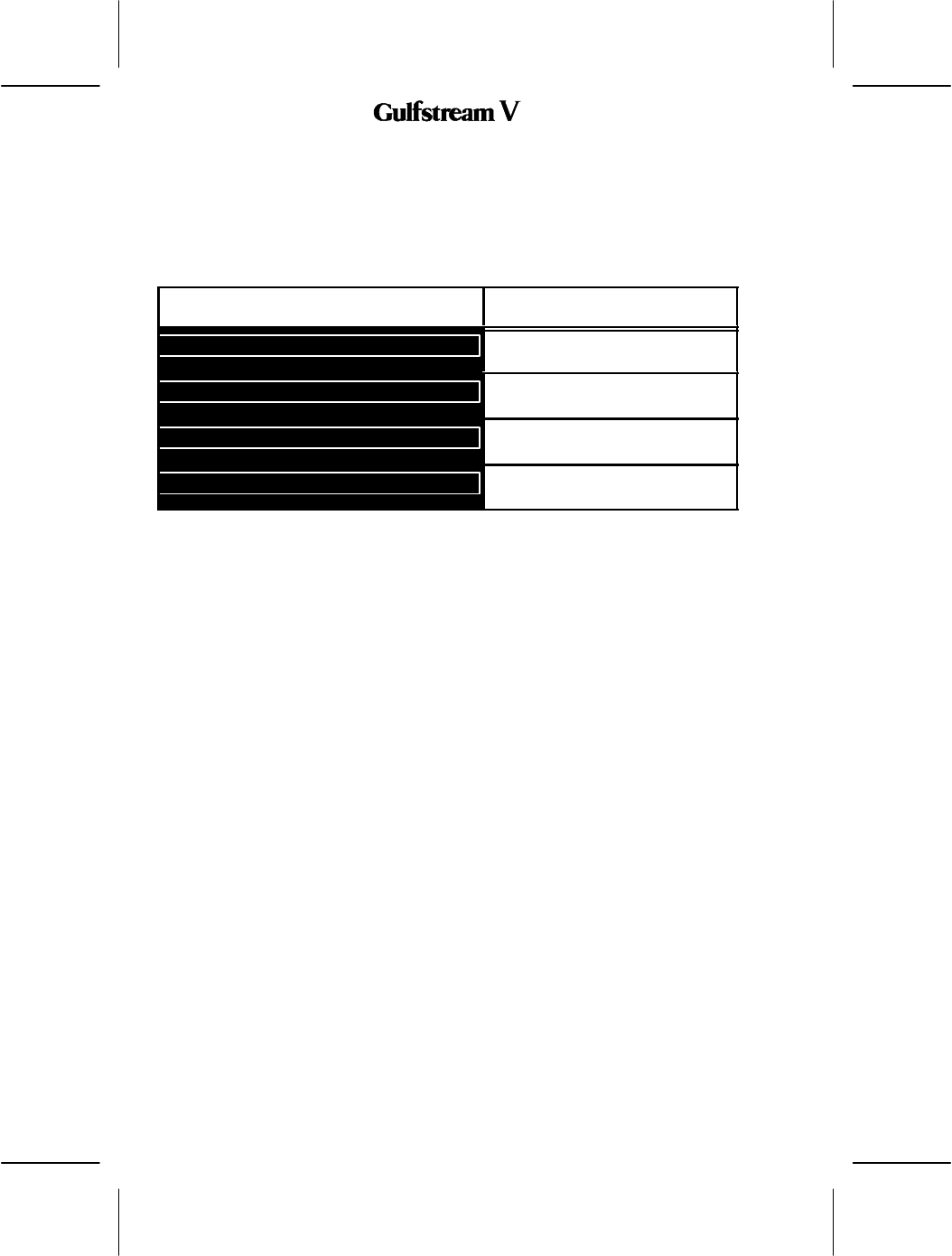
3. Scratchpad Messages
The scratchpad messages described in table , may be generated by the radio tuning
function. In the process of implementing this function, other required messages may come
to light.
Table 34 describes the annunciators on RADIO 2/2.
Annunciator Description
DELETE
This annunciator Indicates that the
value in the scratchpad is deleted.
INVALID ENTRY
This annunciator Indicates that the
entry in the scratchpad is invalid.
SQNO RESPONSE FROM RADIO
This annunciator Indicates that the
squelch noise is coming from the radio.
STUCK MICROPHONE
This annunciator Indicates that the
microphone key is stuck.
RADIO 2/2 Annunciator Descriptions
Table 35
OPERATING MANUAL
2B-09-00
Page 49
Nov 15/02
DIGITAL AUTOMATIC FLIGHT CONTROL SYSTEMS
2B--09--100: DIGITAL AUDIO PANEL
The digital audio panel controls the audio levels and switching for communication between
the aircraft and ground, between the cockpit and cabin, and among the flight crew in the
cockpit.
The Digital Audio Panel is an audio panel that operates off the radio system’s digital audio
bus. Each crew audio panel station can be equipped with a stereo headset including boom
microphone, an oxygen mask microphone, a push to talk (PTT) switch, a hand--held
microphone with PTT and dedicated stereo cockpit speakers.
The audio panel works with the Primus EPIC Modular Radio Cabinet (MRC) system and
network interface module. Radio audio output digitization occurs within the NI--900 in the
remote mounted modular radio cabinet (MRC), even for radios such as the HF and SATCOM
which are not inherently part of the MRC system. There is no separate remote mounted
audio integrating line repair unit (LRU) required. Audio is transmitted digitally from each
side’s cabinet on a shielded twisted wire pair to all audio panels in the system. There are two
audio buses from each cabinet and audio buss configuration (single bus or dual bus) is
program dependent. All audio from an MRC is contained on both digital audio busses.
The audio panel is used for microphone switching to the selected radio over a pair of
redundant digital microphone audio buses to the NI--900. The NI--900 converts the
microphone digital audio data back to analog audio to apply to the selected radio’s MIC input.
Digital encoding of the microphone signals near the source reduces the installation criticality
in avoiding noise and hum pick--up in the audio system.
The audio panel is used to operate intercoms in the cockpit, cabin or maintenance personnel
digitally over the microphone buses. Aural Warning signals can be input into the NI--900 or
audio panel for output on the cockpit speakers or headphones. A cockpit voice recorder
(CVR) output and an option for CVR control is included on the audio panel.
1. Audio Panel’s Role Within The Cockpit
The audio panel interfaces between the pilot’s microphone, cockpit speakers, and
headphones to the respective audio systems in the aircraft such as communication
transceivers, navigation receivers, and intercom systems. In addition to the above, the audio
panel has an intercom function that allows the crew to communicate between themselves.
It also supports the Selective Calling (SELCAL) function, interfaces with the Cockpit Voice
Recorder (CVR), and directs the aural warning audio to the headphones and speakers.

OPERATING MANUAL
2B-09-00
Page 50
Nov 15/02
DIGITAL AUTOMATIC FLIGHT CONTROL SYSTEMS
To interface with the communication transceivers (VHF COMM radios, HF radios, SATCOM,
etc) the audio panel is used to to select the transmitting radio , the listening radio, and adjust
the volume of the received audio and side tone. When communicating using the SATCOM
system, the audio panel has annunciations that indicate an incoming call, a call on hold, and
when a call is being connected. SATCOM can also be used to make a call.
To interface with the navigation receivers (VOR, DME, Marker Beacon, ADF, etc) the audio
panel can select the listening receiver and adjust the audio volume of the received audio.
Additionally, the audio panel can apply filters to the received audio to only allow the NAVAID
IDENTs or Voice to be heard over the receiver.
To interface with the intercom systems such as the cabin communication system, the audio
panel can be used to adjust the cabin audio volume, initiate a call to the cabin and to
announce that a call to the cockpit is being made. The audio panel has two channels for cabin
intercom communications. The first is the normal intercom channel that is designed to
handle routine dialogue. The second is an emergency channel is that is designed to indicate
and handle emergency dialogues. The emergency channel has priority over the normal
intercom channel, so it can interrupt conversations already in progress. However, a normal
intercom call cannot interrupt an emergency call.
In addition to interfacing with the cabin communication system, the audio panel has four
intercom channels and two maintenance (MAINT) channels that are used to communicate
among the flight crew or with the maintenance personnel. This function is performed without
the use of a system, external to the audio panel. This intercom feature allows the flight crew
to use their respective PTT switches, or their VOX levels to initiate the conversation. With
the audio panel, the pilots can select which channel to use and can adjust the volume of the
audio heard in their respective headset.
Miscellaneous features of the audio panel include the ability to select between the oxygen
mask microphone or the boom microphone, the ability to select a backup mode which allows
the flight crew to communicate with a transceiver directly, bypassing the audio panel digital
electronics altogether. Additionally, the audio being directed to the headphones and
speakers is output directly to the CVR for recording and subsequent accident investigation
and aural warnings output by the Aural Warning system are directed, by the audio panel, to
the headphones and cockpit speakers.
2. System LRU Description
The audio panel Digital Audio Panel hardware can switch microphones to various radios,
allow intercom communication, and control the cabin and maintenance intercoms.
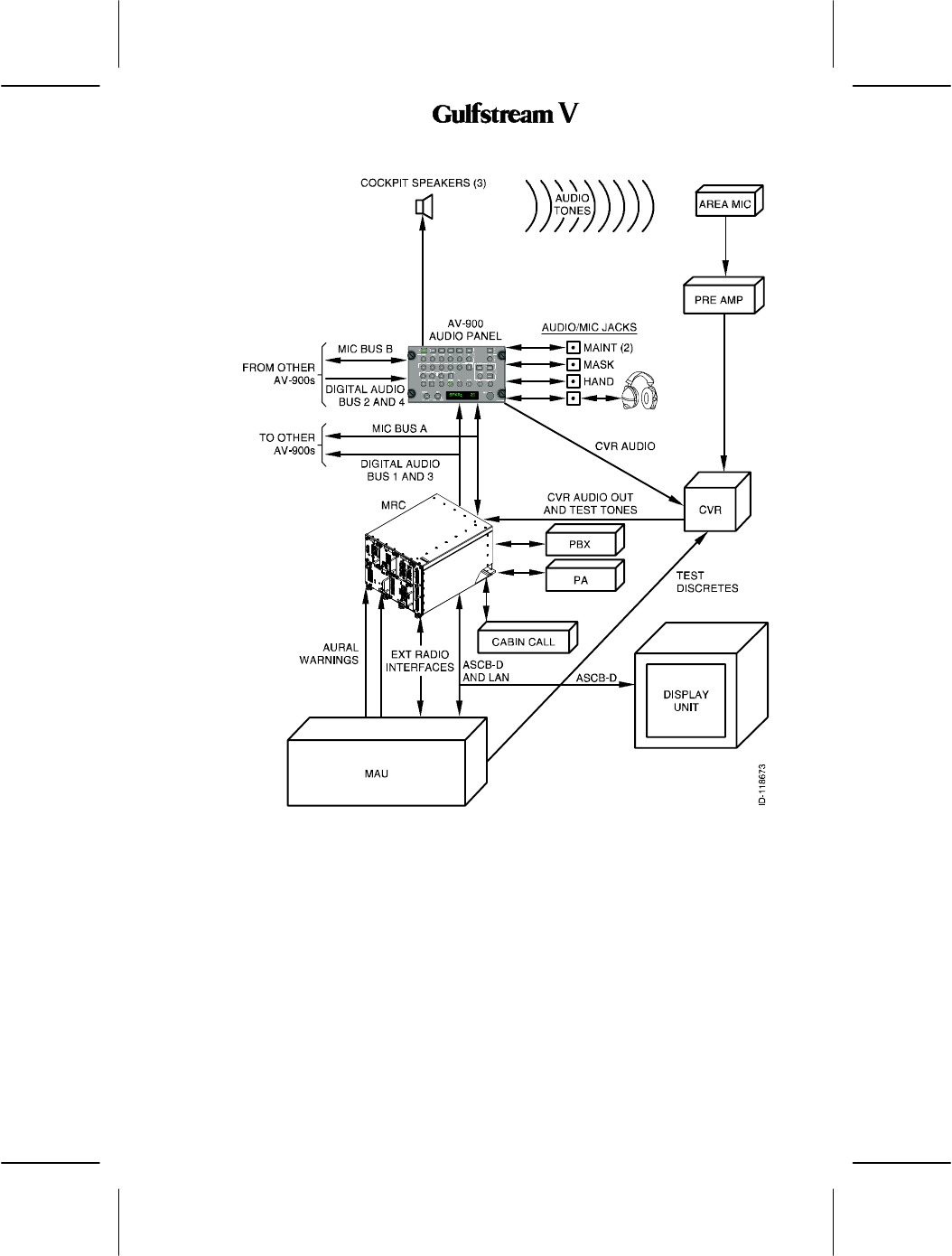
Amplifiers drive headphones, cockpit/cabin speakers and CVR audio outputs. A single side
audio system block diagram for Primus EPIC is shown in Figure 48.
OPERATING MANUAL
2B-09-00
Page 51
Nov 15/02
DIGITAL AUTOMATIC FLIGHT CONTROL SYSTEMS
Figure 48
The primary interfaces for the audio panel are the two pairs of Digital Audio Buses from the
MRCs (One pair from each MRC) and the two redundant Digital Microphone (MIC) buses.
Both MIC buses are connected to each audio panel and each MRC in the system. They
contain identical data.
The MRC includes the Primus II EPIC radio modules and a NI--900 Network Interface Module
(NIM). The NIM contains the audio to digital converters and multiplexing capability to convert
the internal and external radio audio outputs to digital signals on its Digital Audio Bus Output.
The Digital Audio Bus output from each MRC (NI--900) goes to all audio panels in the system.
The Digital Audio Buses from each MRC contain identical multiplexed digital audio samples
from the radios internal and external to the MRC. The audio panel de--multiplexes audio
data, sets levels and converts the selected digital audio samples to analog signals to be
applied to the headphone, speaker and CVR outputs.

OPERATING MANUAL
2B-09-00
Page 52
Nov 15/02
DIGITAL AUTOMATIC FLIGHT CONTROL SYSTEMS
The MIC buses contain multiplexed digital audio samples and control data sent between
audio panels and the Audio Processing Card (APC) inside the NIM. Each unit on the bus
transmits in a pre--determined sequence.
In addition to source and destination addresses, data on each MIC bus consists of the
following:
Data from audio panel to APC
DSelected microphone audio
DPTT status
DCommands/Responses to Commands to/from NIMs
DData from APC to audio panel
DCommand data from ASCB--D
Aural Warning audio from the MAU or other sources
DSELCAL incoming data
DCommands/Responses to Commands to/from audio panel
DData from audio panel to other audio panels
DIntercom channel audio
DPTT status
DCommands/Responses to Commands to/from other audio panels
The NIM contains data interfaces from the audio panel MIC buses to the ASCB--D bus and
from the ASCB--D bus to the Digital Audio Bus, to control and display data to and from the
MAU and Display units.
The NIM also contains audio system interfaces to the following equipment:
DExternal radio equipment such as HF, a 3rd COM, NAVCOM, Radio telephone and
SATCOM.
DAural Warnings from the MAU, or other equipment such as TCAS.
DCabin Call interface to the flight attendant stations.
DExternal Passenger Address System.
DPBX interface for Radio--Telephones such as the Magna--Star system
DCVR Interface
3. General System Requirements
The primary functional requirement for the Digital Audio Panel audio panel is to provide gain
control for numerous communication and navigation audio signals by reading switches, pots
and the encoder on the front of the audio panel and providing attenuation of selected audio
signals proportional to the settings. The audio panel also contains hardware for switching
microphones to various radios and for producing fire bell warning audio. Amplifiers are
provided for driving headphones, speakers, and the cockpit voice recorder. The audio panel
has the ability to route critical signals to the headphones without power.
A. Operation Description
The audio panel receives digitized audio from the remote radio units through one, or
optionally two, pairs of Digital Audio Buses (DABs). Each bus carries data from one Modular
Radio Cabinet (MRC). Digitized audio is routed to the Audio DSP’s serial port where it is
decoded. The Audio DSP modifies the gain (volume) of the various channels, sums the
channels together and performs various filter functions on the audio. The audio then leaves
the Audio DSP and is amplified and routed to the speakers, headphones and CVR . The
audio panel also provides for warning tone amplification.

OPERATING MANUAL
2B-09-00
Page 53
Nov 15/02
DIGITAL AUTOMATIC FLIGHT CONTROL SYSTEMS
The audio panel us used to select microphones (Boom/Hand or MASK mic) and to connect
the desired radio to the selected microphone. The audio panel interfaces with the MRC over
two bi--directional multiplexed Digital MIC busses (both busses contain identical data for
system redundancy). These busses are used for intercom communication in the aircraft,
exchanging status information, communicating configuration changes, sounding warning
tones and providing SELCAL functionality.
The audio panel can route critical signals to the backup COM without power.
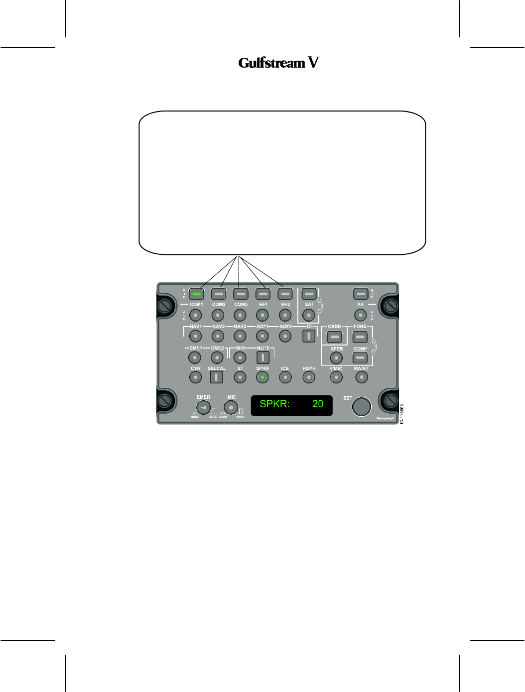
The audio panel consists of three types of buttons:
DRectangular buttons for transceivers
DRound buttons for audio
DSquare buttons for discretes.
The controls include the following:
DNine microphone selection buttons with green LED (light emitting diode) annunciators
which indicate the state of the function controlled by the button (MIC -- rectangular)
-Rectangular and ridged rectangular buttons are used for microphone selection of
associated transceivers such as VHF1 (COM1), VHF2 (COM2), HF1, HF2,
SATCOM, and PA.
-Ridged rectangular buttons are used for frequently used transceivers which may
need to be used in emergency situations such as VHF1, VHF2, and PA. These
ridged rectangular buttons are the same size as the rectangular microphone button
selections but have a ridge on the perimeter of the button so that the button can be
found by feel in low visibility situations.
-Buttons assigned to VHF COM1, and VHF COM2 are designated as SELCAL
channels. This means that when the respective SELCAL channel is enabled the
transceiver annunciates to the pilot that a SELCAL call has been detected. These
buttons support three annunciator states; steady illumination, flashing, and OFF.
Incoming SELCAL calls are indicated with a flashing LED.
-When any of these channels are not SELCAL enabled they operate in the standard
fashion whereby the annunciator toggles between OFF and ON for every
respective button push. Additionally, the annunciator is extinguished should
another rectangular button be pushed.
-Depending on configuration and if SELCAL is enabled, on VHF COM 1 and 2 and
MIC buttons, the annunciator toggles OFF and ON with a short button push (push
and hold for less than one second). When a long button push (push and hold for
one second or longer) is detected the response is slightly different. If the
annunciator is OFF and a long button push is detected on the respective button the
annunciator turns ON. However, if it is ON and long button push is detected the
annunciator remains ON (the purpose is to bring up the display of a feature already
selected without turning it off).
When any of the channels are not SELCAL enabled they operate in the standard
fashion whereby the annunciator toggles between ON and OFF for every respective
button push. Additionally, the annunciator is turned off when another rectangular
button is pushed.
OPERATING MANUAL
2B-09-00
Page 54
Nov 15/02
DIGITAL AUTOMATIC FLIGHT CONTROL SYSTEMS
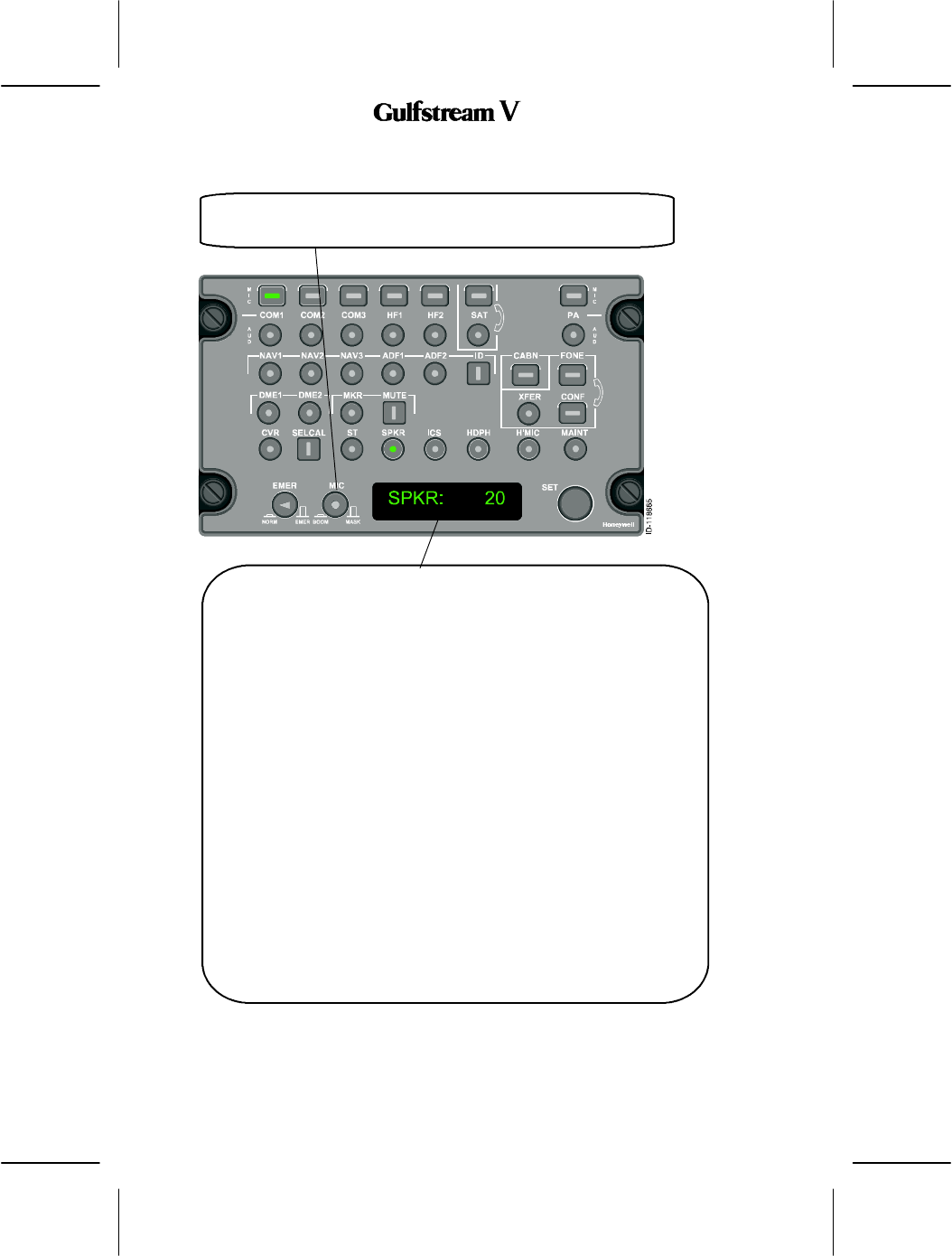
4. Audio Control Panel Switches and Controls
The controls and indicators on the audiot panel are described below.
EMER (Emergency) Microphone Switch -- When the EMER switch is pushed
the following occurs:
DThe on--side microphone is connected directly to the emergency VHF
COM.
DThe emergency VHF COM received audio is connected directly to the
on--side headphone.
DThe emergency VOR/ILS audio is also connected directly to the on--side
headphone (provided it has been selected by the NAV AUDIO switch on the
backup control head).
NOTES: 1. The specification of COM 1, 2, or 3 and VHF NAV 1, 2, or 3 as
the emergency radios is dependent on aircraft wiring.
2. Audio warnings are broadcast through the cockpit speaker.
3. Microphone audio, emergency phone audio, and warning audio
are broadcast to the cockpit voice recorder output.
4. Panel lighting remains lit if power is lost to the audio panel.
OPERATING MANUAL
2B-09-00
Page 55
Nov 15/02
DIGITAL AUTOMATIC FLIGHT CONTROL SYSTEMS
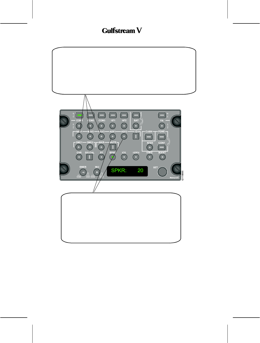
COM1,2,3andHF1,2Buttons-- The audio feedback to the pilot is controlled
by the audio selector button immediately below the microphone button for that
radio. When a radio microphone is selected, the audio feedback is limited to a
minimum level even if the volume set by the audio selector button is zero. This
assures that a transmission does not occur before listening.Normally, the display
shows the radio ID and a number between 0 and 100 showing the relative volume
level for that audio channel.If another audio panel is talking on that radio, the
display shows BUSY and that radio transmit function is temporarily
disabled.When a radio is selected and PTT is pushed, the display shows the
characters representing that radio and TX (for transmitting).If PTT is enabled for
longer than the time--out time (two minutes), the radio transmit function is
disabled and the display shows Stuck Mic (STK MIC).When a microphone
selector button is deselected by pushing it when it is on, or by selecting another
microphone button, both the microphone annunciator and the audio selector
annunciator below it and the audio from that channel go off.
OPERATING MANUAL
2B-09-00
Page 56
Nov 15/02
DIGITAL AUTOMATIC FLIGHT CONTROL SYSTEMS
MIC Switch -- The oxygen mask microphone is selected when this switch
is latched out. When it is latched in, the boom microphone is selected.
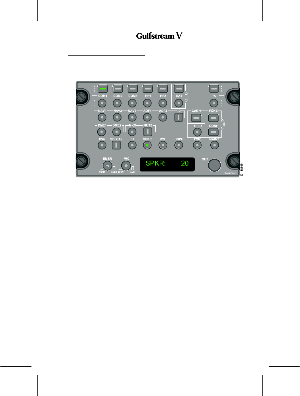
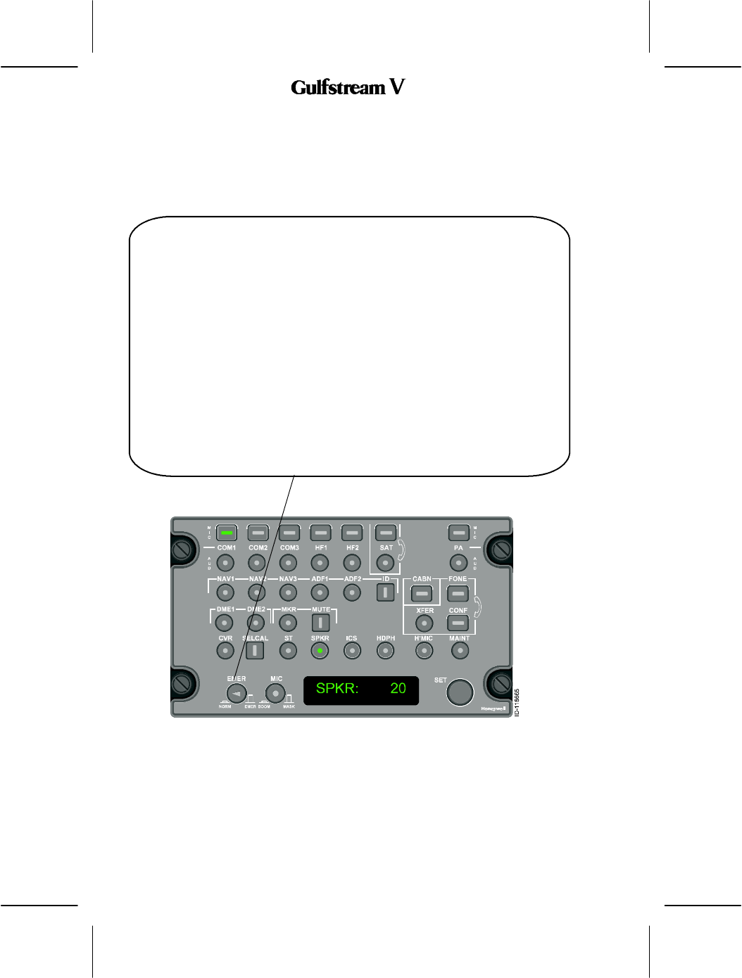
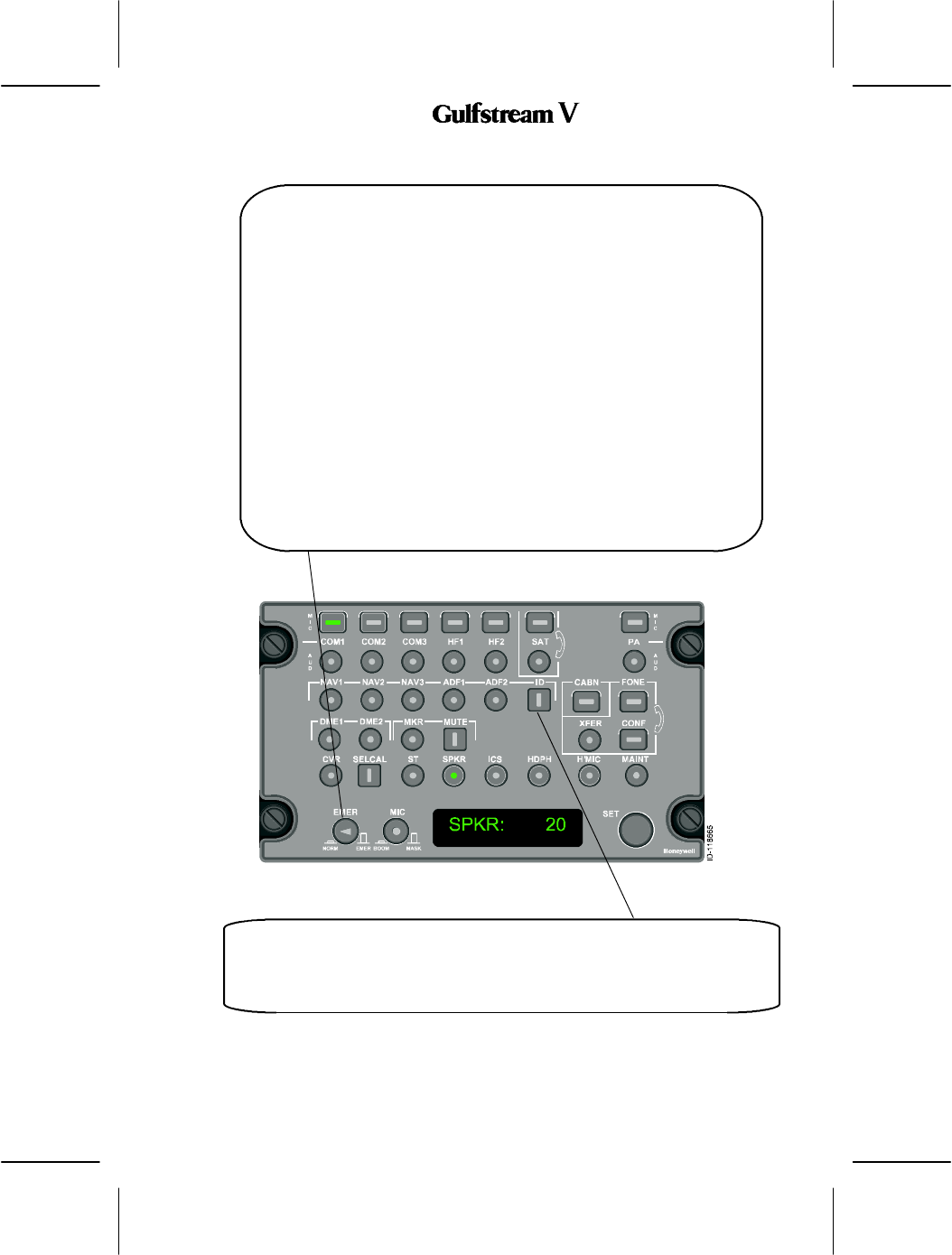
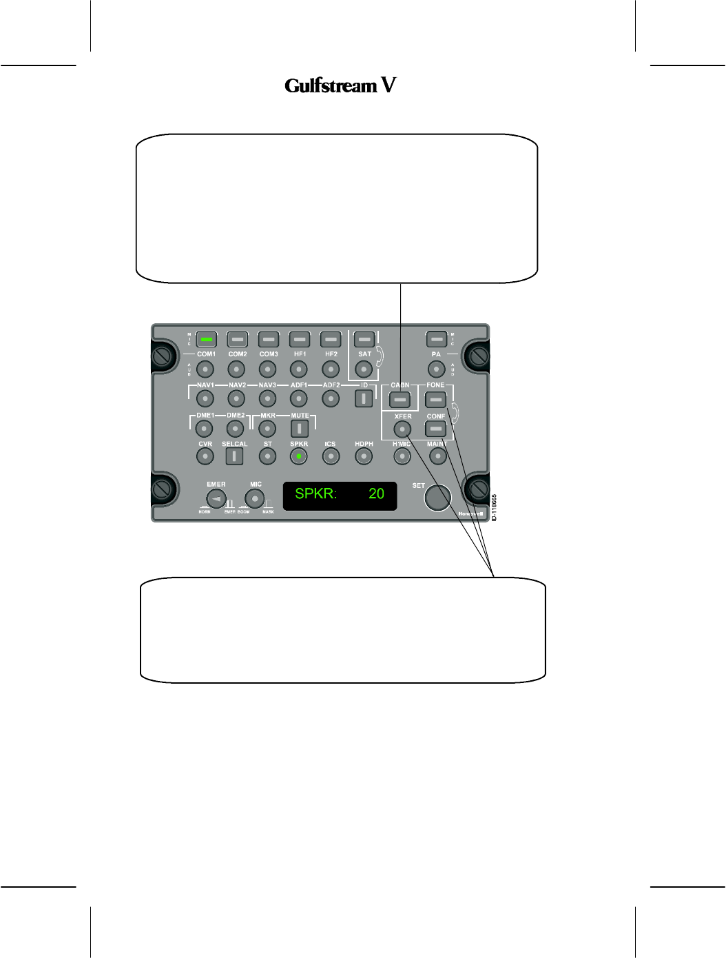
SET Window Display -- The display, which is referred to as the SET
window, is the primary means with which the audio panel provides
feedback to the pilot. One of the major uses of the display is to present
volume levels of selected audio channels and visual feedback of volume
level adjustments. For example, when the COM1 audio selector button is
pushed, the display may show the text, COM1: 47.The text COM1
indicates the button’s function and the text 47 is the variable volume setting
for the COM1 channel.
The display, showing SPKR: 2O, is an eight character display used to
indicate the selected radio (COM1,NAV2, etc.) master headphone
(HDPH), or master speaker (SPKR) volume, which is controlled with the
SET knob, and its current relative volume setting (1--99).
The primary action that defines the text displayed in the SET window is the
pushing of the rectangular microphone buttons, round audio buttons,
square discrete selector buttons, the turning of the SET knob, and the
pushing of the push--to--talk buttons. In addition to these actions, many of
the displays in the SET window are timed, reverting to a default display after
a timeout period has expired.
The display can also indicate other status, setup, and test information. The
logic for the text displayed in the SET window is captured in the state
machine which is made up of eight display states; NO SOUND, ACTIVE
AUDIO, DEFAULT HDPH, DEFAULT SPKR, TRANSMIT, and NO
TRANSMIT. Table 36 lists the states and includes a description of these
states.
OPERATING MANUAL
2B-09-00
Page 57
Nov 15/02
DIGITAL AUTOMATIC FLIGHT CONTROL SYSTEMS
State Description
NO SOUND
(STUCK MICROPHONE)
NO SOUND is displayed in the SET window
(STUCK MICROPHONE replaces the NO SOUND state)
ACTIVE AUDIO SET window displays the nomenclature for the active
audio channel and the corresponding volume control
DEFAULT HDPH SET window displays the nomenclature for the button
assigned to headphone and the corresponding level
DEFAULT SPKR SET window displays the nomenclature for speaker and
the corresponding volume level
TRANSMIT SET window displays the nomenclature for the button
assigned to the active radio with the text TX in place of
the volume indication. This annunciates that this radio is
transmitting
NO TRANSMIT SET window displays the text NO TX to indicate to the
pilot that no radio is currently selected for transmission
ACTIVE DISCRETE SET window displays the nomenclature for the active
discrete nomenclature that corresponds to the square
button pushed
SPECIAL SET window display is controlled by requirements due to
the special nature of the display needs
SET Window Annunciations
Table 36
When an audio button is pushed the SET window displays the nomenclature for the button
pushed. This display exists for the display time which is set in the configuration database.
When this time is exceeded the SET window reverts to the default display which is either the
nomenclature/volume of the headphone or the speaker provided these buttons have been
selected.
After the display has reverted to the default display or another audio button has been pushed,
the SET window can be returned to a previous selection by using a long button push. This
brings up the display of a feature already selected without turning it off.
Headphone (HDPH) and speaker (SPKR) buttons are special forms of audio buttons. Their
uniqueness is due to the fact that their SET window display is the default display. For
example, if the ADF 1 button is pushed the nomenclature for the ADF 1 is displayed in the
SET window. However, if the display time limit in the configuration database is exceeded the
SET window reverts to the default display, either the nomenclature for the speaker or
headphone. Additionally, there is a priority between the two default displays. Headphone has
priority over speaker since this is the most likely to be used by the flight crew.
The SET window display logic adjusts slightly when a stuck microphone condition is
detected. Under this circumstance the default displays of headphone and speaker go away,
the NO SOUND display goes away being replaced by STUCK MICROPHONE text. This
provides a reminder to the flight crew that the microphone PTT is defective and another
means of communication with the radios should be found.
The SET window special state is used for various functions such as FONE and STUCK
MICROPHONE which have special display needs to support the function. The SET window
display can be entered from any state and returns to the state as previously described.
OPERATING MANUAL
2B-09-00
Page 58
Nov 15/02
DIGITAL AUTOMATIC FLIGHT CONTROL SYSTEMS
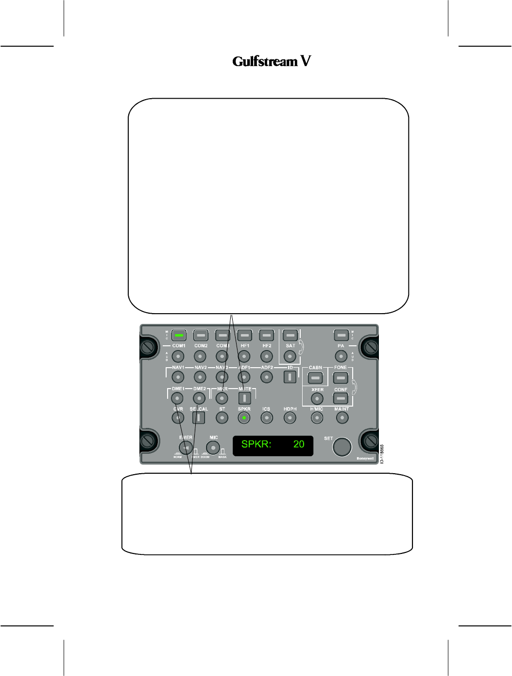
NAV 1,2,3 -- If the audio panel is in receive mode and the NAV selector is
selected, the audio panel amplifies the NAV signal by the gain value set by the
pilot before outputting it to the headphones or speakers.
If the audio panel is on--side transmit, the audio panel mutes the NAV audio to
the speaker and headphone.
If the NAV volume setting is set to zero, the audio panel closes the squelch bit
of the NAV channel. Otherwise, the audio panel opens the squelch bit of the
NAV channel.
ADF 1, 2 -- When the ADF audio selector is selected, the
audio panel amplifies the ADF signal by the gain value set by
the pilot before outputting it to the headphones or speakers.
If the audio panel is on--side transmit, the audio panel mutes
the ADF audio to the speaker and headphone.
If the ADF volume setting is set to zero, the audio panel
closes the squelch bit of the ADF channel. Otherwise, the
audio panel opens the squelch bit of the ADF channel.
OPERATING MANUAL
2B-09-00
Page 59
Nov 15/02
DIGITAL AUTOMATIC FLIGHT CONTROL SYSTEMS
MKR (Marker) /MUTE Buttons -- The audio panel provides one control
interface for the louder marker of the two incoming marker tones. The audio
panel mutes the weaker marker.
If the audio panel is in the receive operation and the marker volume control is
set below the minimum gain, the marker audio is set to the minimum gain value.
If the marker selector is selected, the audio panel amplifies the marker signal
by the gain value set by the pilot before outputting it to the headphones or
speakers.
If the audio panel is on--side transmit, the audio panel mutes the marker audio
to the speaker and headphone.
If the marker volume setting is set to zero, the audio panel closes the squelch
bit of the marker channel. Otherwise, the audio panel opens the squelch bit of
the marker channel.
The marker tones are muted when the pilot pushes the MUTE button. The
marker audio remains muted as long as the marker audio level is above the
mute level preset in the configuration. When marker audio drops below mute
level, the marker audio remains muted for five seconds. If the mute button is
pushed during this five second window, the marker audio is muted for 20
seconds. If the marker audio goes above the mute level during this 20--second
period, the marker audio remains muted as long as the marker audio is above
the mute level.
DME -- If the audio panel is in receive mode and the DME selector is selected, the
audio panel amplifies the DME signal by the gain value set by the pilot before
outputting it to the headphones or speakers.
If the audio panel is on--side transmit, the audio panel mutes the DME audio to the
speaker and headphone.
If the DME volume setting is set to zero, the audio panel closes the squelch bit of the
DME channel. Otherwise, the audio panel opens the squelch bit of the DME channel.
OPERATING MANUAL
2B-09-00
Page 60
Nov 15/02
DIGITAL AUTOMATIC FLIGHT CONTROL SYSTEMS
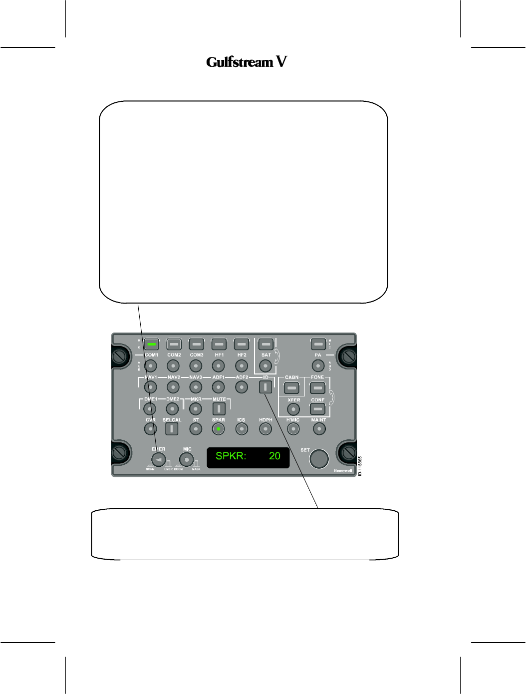
Emergency (EMER) Microphone Switch -- When the EMER button is pushed,
the following occurs:
DThe on--side microphone is connected directly to the emergency VHF
COM.
DThe emergency VHF COM received audio is connected directly to the
on--side headphone.
DThe emergency VOR/ILS audio is also connected directly to the on--side
headphone (provided it has been selected by the NAV AUDIO button on
the backup control head).
In addition to the above emergency operations, the Audio Panel EMER switch
does the following:
DAudio warnings are broadcast through the cockpit speaker.
DMicrophone audio, emergency phone audio, and warning audio are
broadcast to the cockpit voice recorder output.
DPanel lighting remains lit if power is lost to the audio panel.
When EMER is selected, headphone volume is controlled by the on--side
headphone volume control. The EMER button disables all other audio panel
controls.
ID Button -- When the ident filter (ID) is enabled by pushing the ID button, a filter
is activated that eliminates the voice on VOR and ADF audio. The annunciator
on the button is on when the filter is active. When the ident filter is deselected,
voice and ident are available. The annunciator is off.
OPERATING MANUAL
2B-09-00
Page 61
Nov 15/02
DIGITAL AUTOMATIC FLIGHT CONTROL SYSTEMS
Emergency (EMER) Microphone Switch -- When the EMER button is pushed,
the following occurs:
DThe on--side microphone is connected directly to the emergency VHF
COM.
DThe emergency VHF COM received audio is connected directly to the
on--side headphone.
DThe emergency VOR/ILS audio is also connected directly to the on--side
headphone (provided it has been selected by the NAV AUDIO button on
the backup control head).
In addition to the above emergency operations, the Audio Panel EMER switch
does the following:
DAudio warnings are broadcast through the cockpit speaker.
DMicrophone audio, emergency phone audio, and warning audio are
broadcast to the cockpit voice recorder output.
DPanel lighting remains lit if power is lost to the audio panel.
When EMER is selected, headphone volume is controlled by the on--side
headphone volume control. The EMER button disables all other audio panel
controls.
ID Button -- When the ident filter (ID) is enabled by pushing the ID button, a filter
is activated that eliminates the voice on VOR and ADF audio. The annunciator
on the button is on when the filter is active. When the ident filter is deselected,
voice and ident are available. The annunciator is off.

OPERATING MANUAL
2B-09-00
Page 62
Nov 15/02
DIGITAL AUTOMATIC FLIGHT CONTROL SYSTEMS
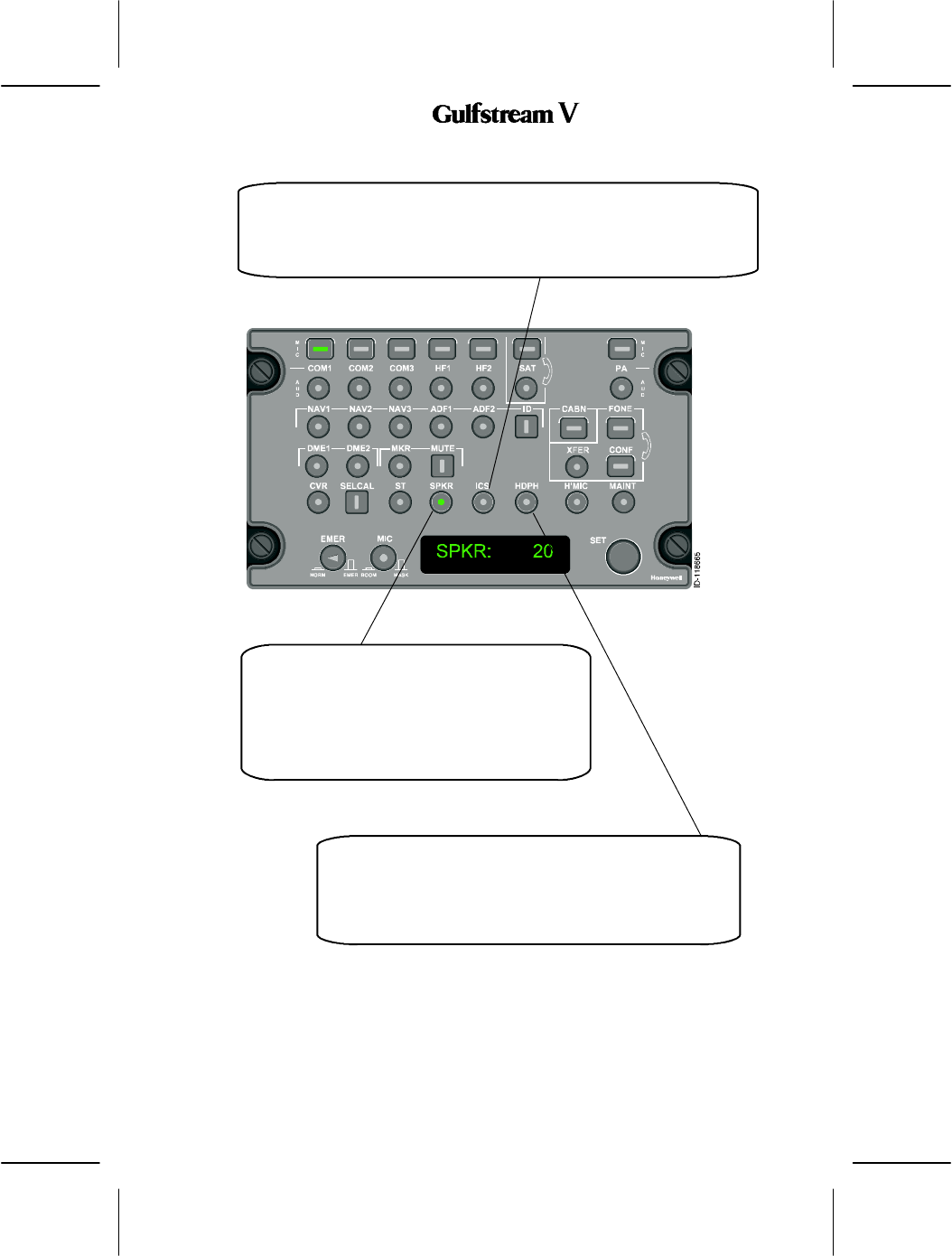
SELCAL Button -- An incoming call is displayed when the SELCAL
annunciator flashes. Also the microphone and the audio button for the called
radio flashes. Resetting to turn off the flashing annunciators is done by pushing
the SELCAL button. The SELCAL button, when pressed, shows the SELCAL
code on the audio panel display.To attend the call, the microphone button for
the called radio is selected and PTT enabled.
CVR (Cockpit Voice Recorder) Button -- When this
button is pushed, the audio is output to the CVR. The
output comes from the following sources:
D
Unsquelch audio signals from each
boom, mask,or hand microphone in use
D
Audio sent to the cockpit speaker
D
Audio sent to the pilot’s headphone
SET Knob -- The common volume control knob adjusts the
volume of the most recently selected audio or the one that is
displayed in the display window. Adjusting the knob clockwise
increases the volume. The relative volume is shown on as a
number between 01 an 99 on the SET display.
OPERATING MANUAL
2B-09-00
Page 63
Nov 15/02
DIGITAL AUTOMATIC FLIGHT CONTROL SYSTEMS
SPKR (Speaker) -- Pushing the SPKR button,
lights the button and SPKR is displayed in the
display with a relative volume level number.
Adjusting the volume control sets the speaker
volume level for all audio inputs. Each one can
still be individually controlled when its audio
button is pusheded and its ID displayed.
HDPH (Headphone) -- Pushing the HDPH button lights the
button and HDPH is displayed in the SET display with a
relative volume level number. Adjusting the SET knob sets
the headset volume level for all audio inputs. Each one can
still be individually controlled when its audio button is pressed
and its ID displayed.
ICS (Intercom System) Button -- Pushing the ICS button lights the button
and ICS is displayed in the SET display with a relative volume level number.
This enables the intercom system so the crew can talk with each other.
Adjusting the SET knob sets the headset volume level for all audio inputs.
OPERATING MANUAL
2B-09-00
Page 64
Nov 15/02
DIGITAL AUTOMATIC FLIGHT CONTROL SYSTEMS
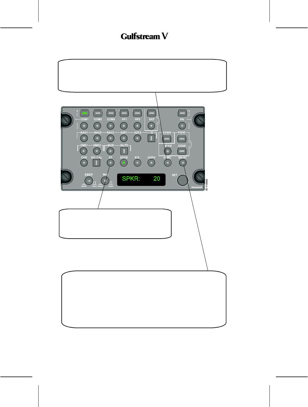
ST (Side Tone) -- Pushing the ST button, lights
the button . With sidetone active, the sidetones
in the crew’s headsets can be adjusted by
turning the ST button.
H’MIC Switch -- Pushing the H’MIC button lights the button and H’MIC is
displayed in the SET display with a relative volume level number. When the
H’MIC switch is latched out, the on’side microphone acts as the hot mike for
intercome. In the latched in position, the on--side mike is connected to the
intercom PTT switch. Adjusting the SET knob sets the headset volume level
for all audio inputs.
MAINT Button -- Pushing a button on the pilot’s left console sounds a horn
in the nose wheel well to summon maintenance personnel. When MAINT is
selected on the audio panel, and hot microphone is enabled, the pilot
microphone signal is routed to the headset in the nose wheel. There are
provisions for three maintenance interphone connections.When MAINT is
selected, the display shows MAINT CALL, and the annunciator button
flashes until the call is picked up by the ground crew. At this time, the display
shows the characters denoting RAMP and a number between 0 and 100
representing the volume level.If another audio panel is talking on the ramp,
the display shows BUSY and the ramp function is disabled.
OPERATING MANUAL
2B-09-00
Page 65
Nov 15/02
DIGITAL AUTOMATIC FLIGHT CONTROL SYSTEMS
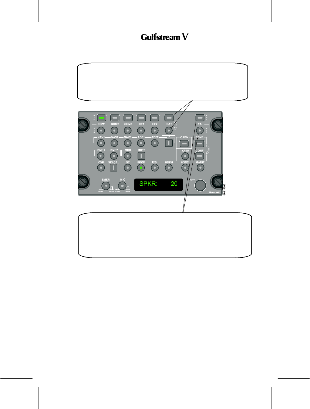
PA (Passeger Address) Buttons -- The two PA buttons are used to control
the aircraft’s passenger address system.When the rectangular button is
pushed, the button lights, and the round button also lights to indicate that the
PA is in use. The pilot’s current mike is connected to the PA system and
announcments to the passenger compartment can be made. PA volume is
controlled by the round PA button. The pilot pushes to unlatch the rectangular
button to turn off the PA system. Both button annunciators go off.
SAT Buttons -- The two SAT buttons are used to control the SATCOM
telephone system. The rectangular button flashes and a chime sounds to
indicate an incoming SATCOM call. Both the round and rectangular buttons go
on steadily when the line is in use. The rectangular button is used to connect
and disconnect the SATCOM calls. The pilot disconnects SATCOM by pushing
the rectangular button again. At this time, all SATCOM annunciator lights go off.
OPERATING MANUAL
2B-09-00
Page 66
Nov 15/02
DIGITAL AUTOMATIC FLIGHT CONTROL SYSTEMS
CABN Button -- When CABN is pushed, the SET display shows CABN CALL, and
the annunciator button flashes until the call is picked up by the flight attendant. At
this time, the display shows the characters denoting CABN and a number between
0 and 100 denoting the volume.The Digital Audio System interfaces with the
Passenger Address System in order to allow the flight crew in the cockpit to
perform passenger announcements, to communicate with the flight attendants and
to provide call chimes. The call chimes are annunciated at the beginning of the call
from the cockpit to the flight attendants and vice--versa. The chimes are also
annunciated before the pilots or flight attendants make announcements to the
passengers.If another audio panel is talking to the cabin, the display shows
”BUSY” and the cabin function is disabled.
FONE, XFER and CONF Buttons -- These buttons are
associated with the MAGNASTAR phone system. Their
functions are TBD.

OPERATING MANUAL
2B-09-00
Page 67
Nov 15/02
DIGITAL AUTOMATIC FLIGHT CONTROL SYSTEMS
5. Operational Modes
The audio panel operates in one of five of modes:
DNormal Operational Mode.
DSoftware Loading Mode
DBackup (BKUP) Mode.
DConfiguration Mode
DAPC Test Mode
A. Normal Operational
During normal operation, the audio panel consists of 30 audio channels some of which are
dedicated and others which can be customized by the pilot. The 30 channels are used to
support the following functions during Normal mode operations:
DRadio Receiver
DRadio Transceiver
DIntercom
DCVR
DPA
DTelephony
DSELCAL
The aural warning function is supported by the audio panel based upon inputs from the NIM.
The audio panel controls audio and transmission to the following:
DTwo dedicated VHF channels
DEight auxiliary transceiver channels
DFive intercom channels
DOne maintenance intercom channel
DDedicated navigation audio channels
DFour auxiliary navigation audio channels
DA single CVR channel.
The dedicated navigation receivers are the VOR, VIDL, ADF, Marker (MKR), DME, and MLS.
B. Radio Receiver
Radio receiver audio channels support radio reception only (i.e. VHF NAV, ADF, MKR, MLS
and DME). These channels receive digitized, multiplexed audio data from the MRC over the
digital audio busses. The audio panel decodes, filters, applies gain to the selected digitized
channels, converts the samples to analog audio, and outputs the analog audio to the
Headphones, Speakers, and CVR.
C. Radio Transceiver
Radio transceiver audio channels support reception and transmission of audio on both the
dedicated and auxiliary transceiver channels. The received audio from these transceivers
is received on the digital audio buses from the MRC radio cabinet. The audio panel decodes,
filters and amplifies/attenuates, convert the samples to analog audio, and outputs the analog
audio on the Headphones, Speakers and CVR output ports.
The transmitted audio is sent to the MRC radio cabinet over the MIC bus. The audio
originating from the selected microphone is sampled, digitized, filtered, amplified/attenuated,
and multiplexed onto the MIC bus. Additionally, a sidetone is created for feedback to the
crewman either through the headset or through the speakers on the flight deck or both.

OPERATING MANUAL
2B-09-00
Page 68
Nov 15/02
DIGITAL AUTOMATIC FLIGHT CONTROL SYSTEMS
D. Intercom
The Intercom function is used so crew memebers can talk to each other on the selected
cockpit intercom, cabin intercom, or maintenance intercom, when they are not using a COM
radio. Transmission on the intercom is enabled by either selecting intercom PTT or enabling
a hot mic function. An Intercom volume control is provided to attenuate audio from the
intercom. It operates in the same manner as the transceiver volume controls, except that
the intercom output is sent to the headphones only if the mask microphone is not being used.
If the mask microphone is being used, the intercom output is sent to the speakers.
E. Cockpit Voice Recorder (CVR)
The audio panel sums and outputs the following signals to the CVR:
DAudio output from the cockpit speakers including warnings.
DAudio output from the headphone outputs including warnings.
DAudio input from the selected microphone.
In addition to the summing and outputting of audio to the CVR, the audio panel also contains
CVR control features. From the audio panel the crew can initiate the CVR erase and test
functions which are hosted by the CVR equipment.
F. Passenger Address (PA)
The audio panel can be used to provide an internal Passenger Address (PA) function or it
may be used to select and support an external PA function. Internal selection allows the flight
crew to make an announcement to the cabin. A crew member is able to transmit on the PA
output by selecting and keying the PA microphone button.
The audio panel external PA function is initiated by assigning an auxiliary transceiver to this
feature and connecting it to an external PA system via the MRC radio cabinet.
G. Telephony
The audio panel interfaces with all telephonic equipment on board the aircraft through the
MRC and provides the necessary telephonic functions through this interface. The telephonic
functions contained in the audio panel are call pick--up, call hang--up, call transfer, and call
hold. These are done using the front panel buttons.
H. Selective Call (SELCAL)
Using the Selective Call (SELCAL) function, the crew can receive calls from a ground station
designated to the aircraft. The audio panel is the interface for the pilot to set the
aircraft--unique SELCAL code designated for the aircraft. Selecting the code is possible only
when the aircraft is on the ground. The SELCAL code selection can also be performed using
the CCD and displays and transmitting to the MRC NIMs via ASCB. The NIMs encode the
SELCAL code on the DIGITAL MIC Bus.
The SELCAL code is displayed on the audio panel by selecting the SELCAL button.
I. Aural Warnings
The audio panel sums and outputs the following audio signals to speakers, headphones and
CVR output:
DWarning Audio from the analog warning inputs.
DWarning Audio from the MIC bus inputs.
J. Software Loading
Software is loaded (by manufacturing or authorized Honeywell support centers) into the
audio panel before the audio panel is installed aboard an aircraft, or it is loaded by executing
an on--aircraft software loading sequence. The on--aircraft loading sequence requires the
audio panel to be in the software loading mode.

OPERATING MANUAL
2B-09-00
Page 69/(70 blank)
Nov 15/02
DIGITAL AUTOMATIC FLIGHT CONTROL SYSTEMS
K. APC Test Mode
An APC test mode is is used to validate nominal autio panel operation. While in this test mode
the audio panel continuously echoes back a test pattern to the requesting NIM. When the
NIM stops requesting, the testing stops and the audio panel returns to normal operation. (I
don’t see a TEST button.)