Honeywell DMA-37B2 DMA-37B DME Interrogator, 066-50013-1101, -1212 User Manual MM DME 37B DME System 1137 1 Rev 3
Honeywell International Inc. DMA-37B DME Interrogator, 066-50013-1101, -1212 MM DME 37B DME System 1137 1 Rev 3
UserManual.wiki
>
Honeywell
>
DMA 37B2 User Manual
Users Manual
Navigation menu
Upload a User Manual
Namespaces
Wiki Guide
HTML
PDF
Info
Views
User Manual
Discussion / Help
Navigation
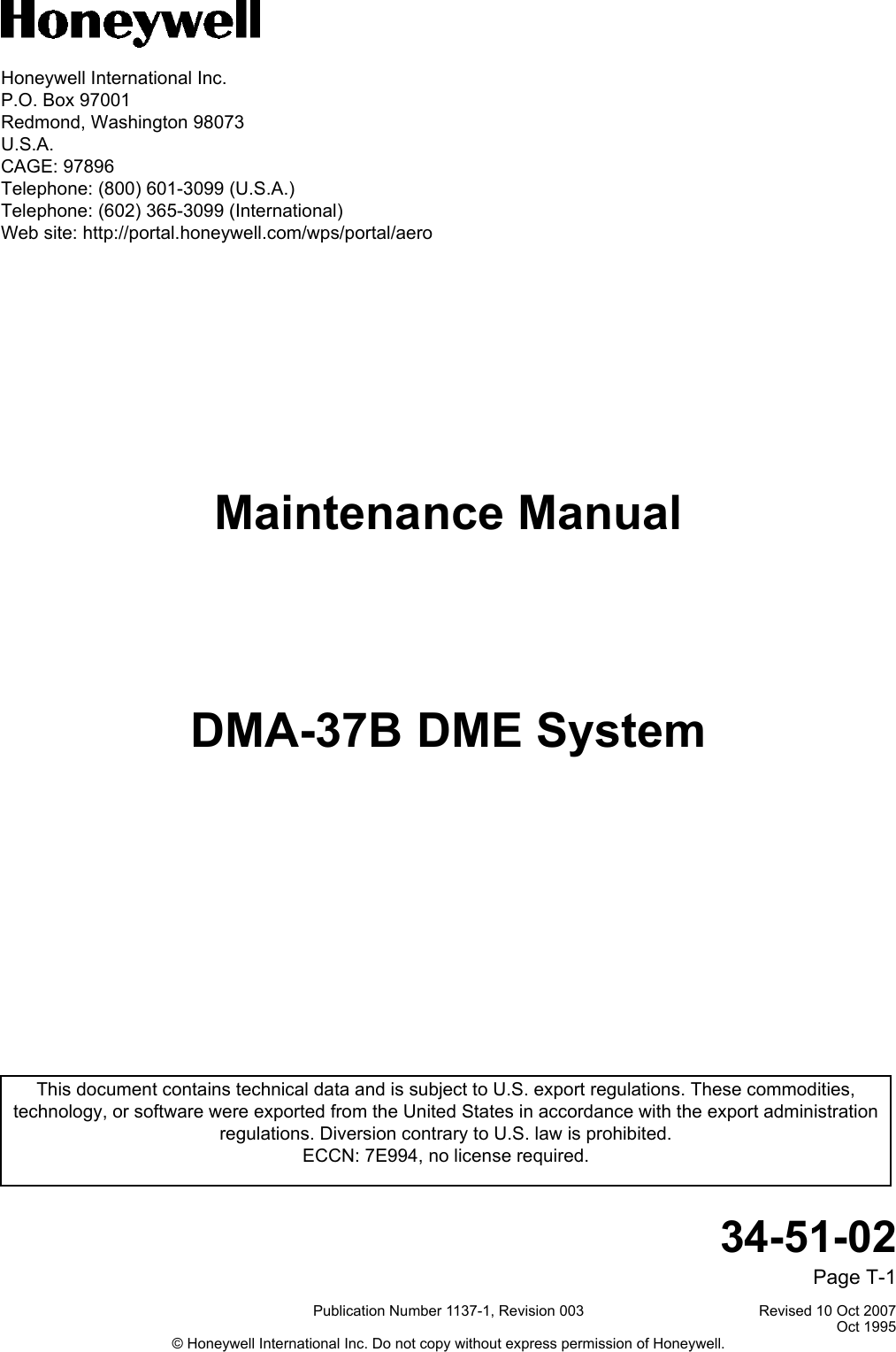

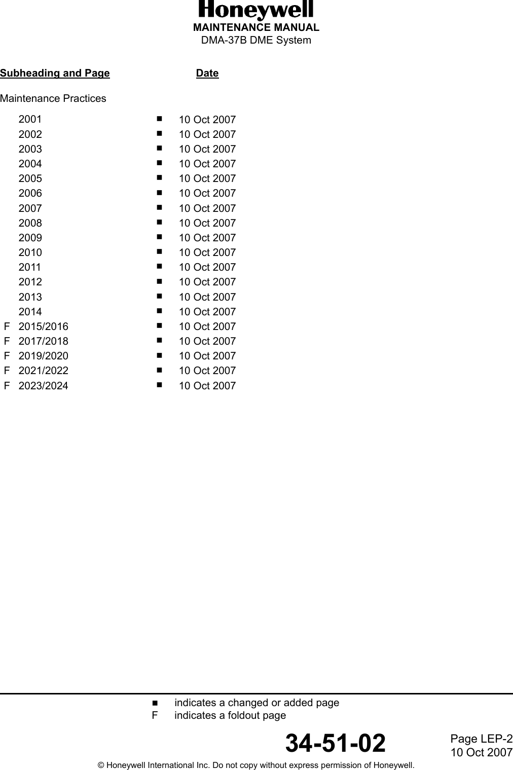
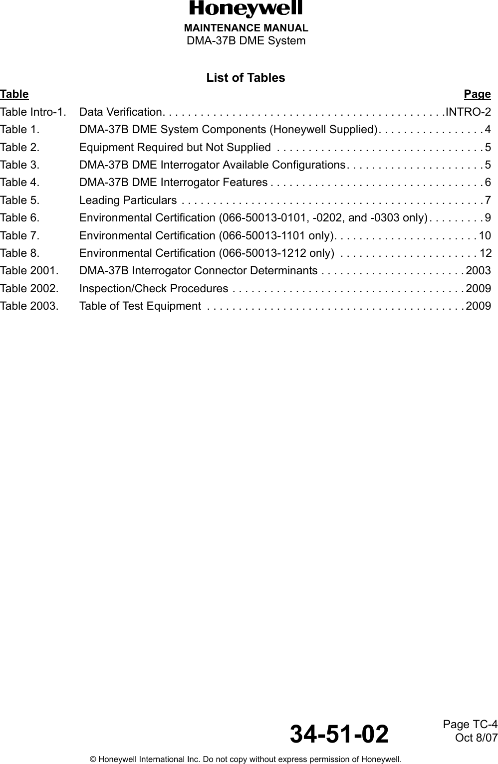
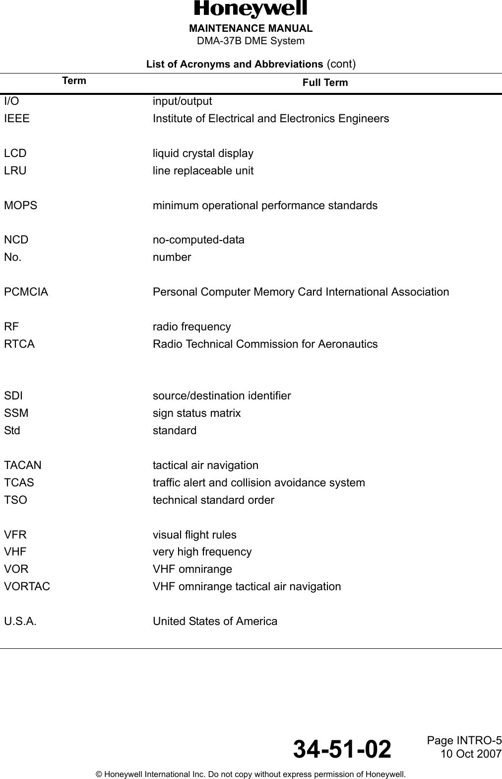
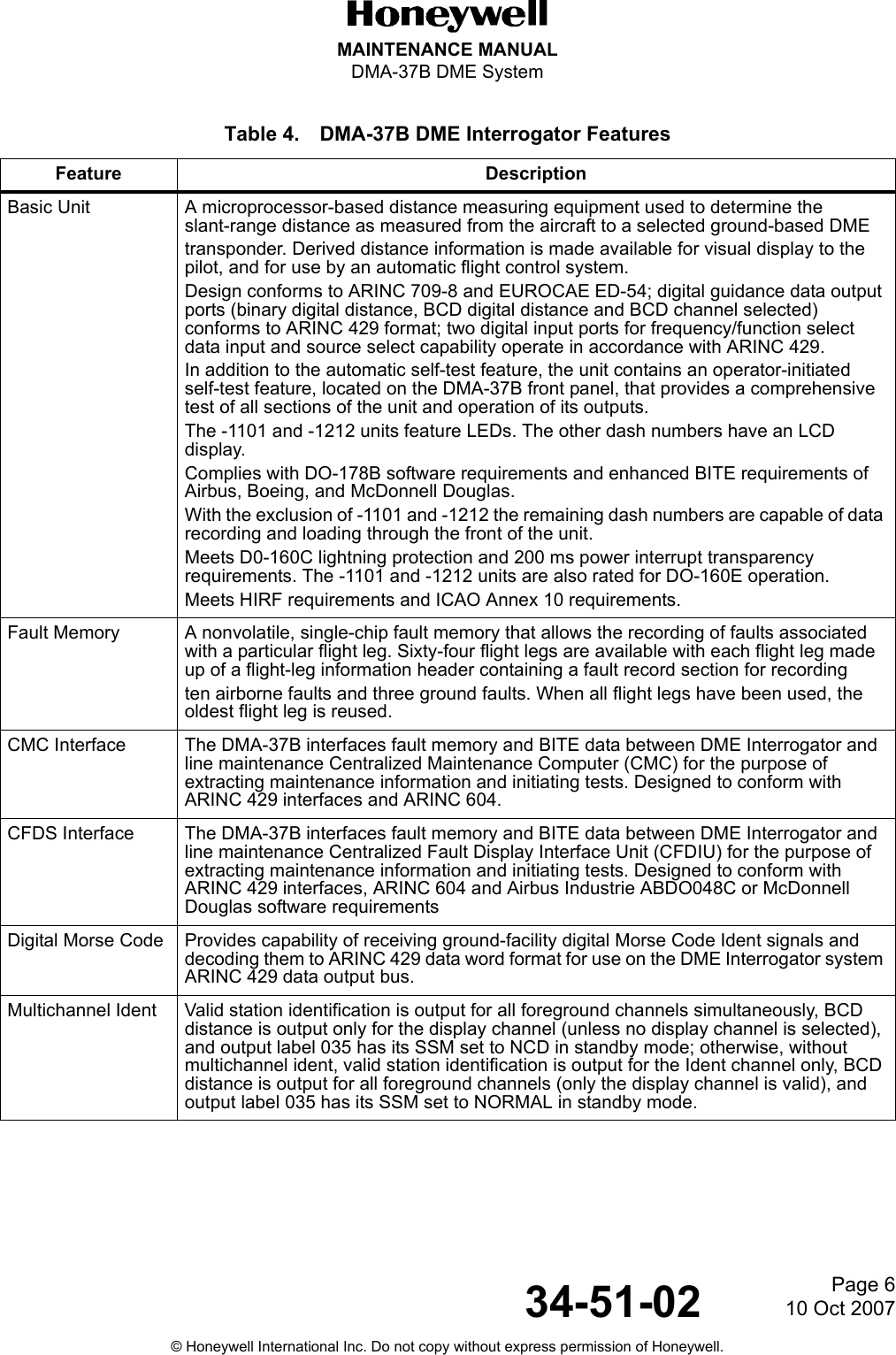
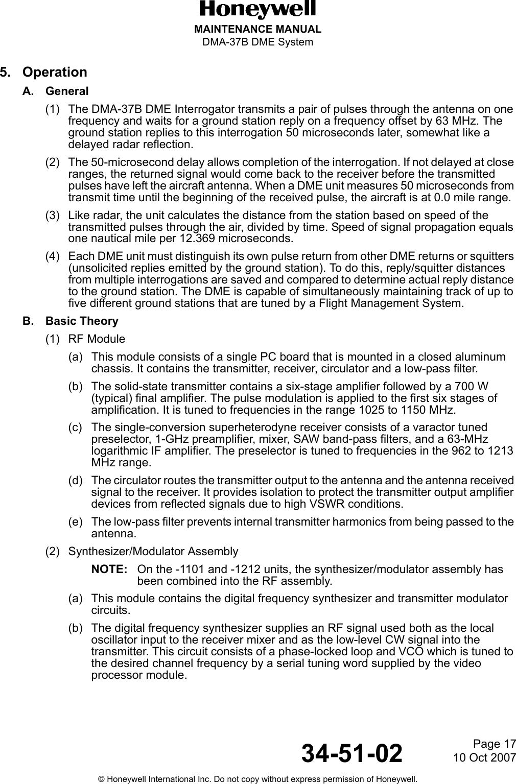
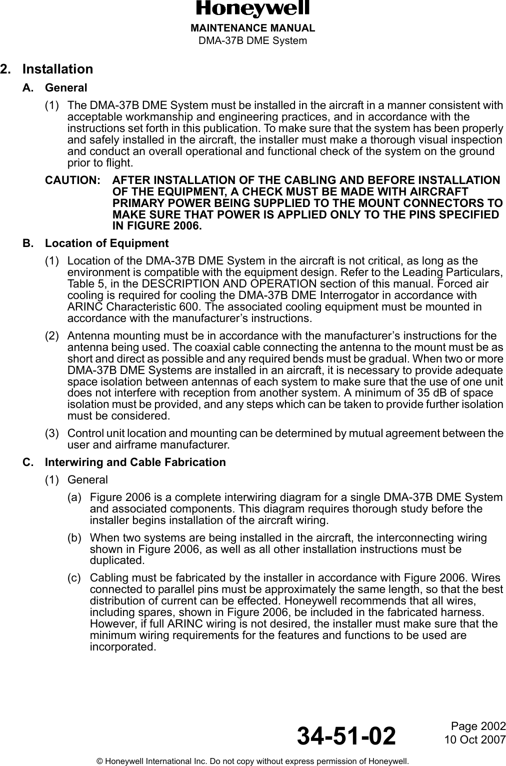
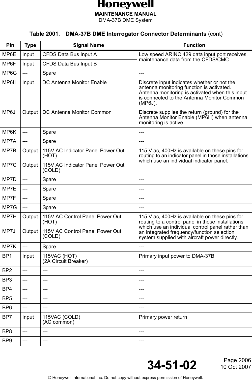
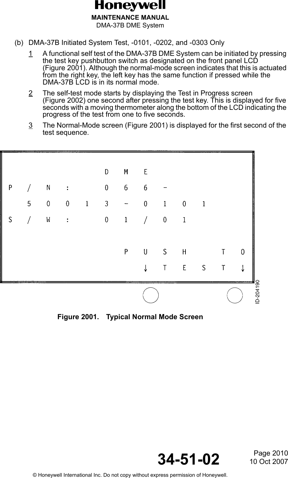
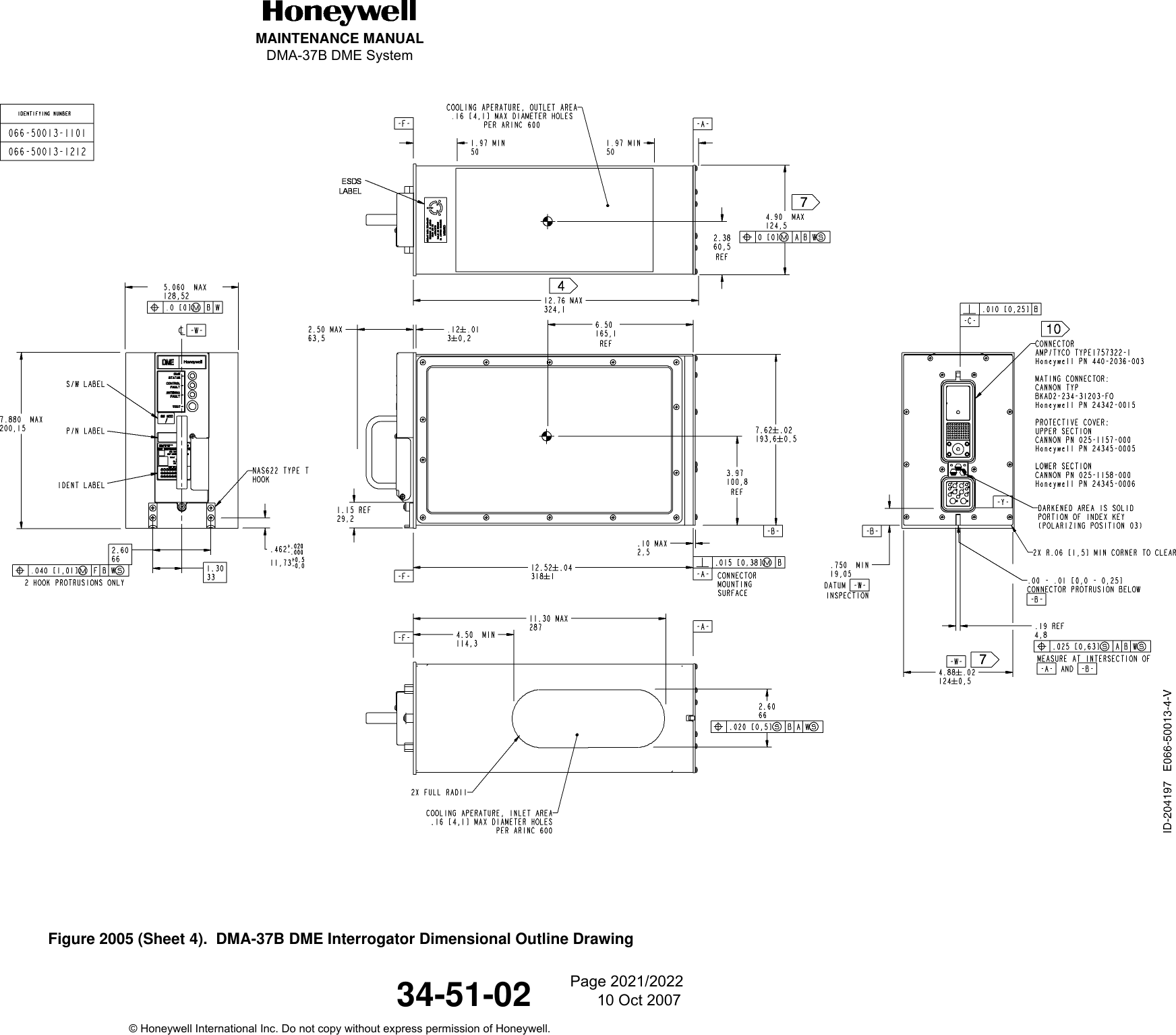
![Page 710 Oct 200734-51-02MAINTENANCE MANUALDMA-37B DME System© Honeywell International Inc. Do not copy without express permission of Honeywell.2. System Leading ParticularsA. Unit Specifications(1) Table 5 lists the leading particulars for the DMA-37B DME System.Table 5. Leading ParticularsCharacteristics DescriptionGeneralPower Requirements 115 V ac, 380 to 420 Hz, 22 W (-0101, -0202, and -0303 only)115 V ac, 360 to 800 Hz, 25 W (-1101 and -1212 only)Weight 9.8 lb (4,45 kg)Dimensions See Figure 2005.Form Factor ARINC 600 4 MCUCooling ARINC 600 forced airTemperature• Operating -67 to +158 °F (-55 to +70 °C) for -0101, -0202, and -0303 only+5 to +158 °F (-15 to +70 °C) for -1101 and -1212 only• Storage -85 to +158 °F (-65 to +85 °C)Humidity Zero to 95% Relative HumidityWarm-up period Stable operation within one minute after application of powerFrequency Selection Serial digital in accordance with ARINC 429Range Zero to 300 Nautical MilesAltitude 50,000 feet above mean sea levelVelocity Zero to 1000 KnotsSelf Test Continuous, automatic; Manual from discrete ARINC 429, CMC, or Front PanelIntegrity Monitoring Continuous self-monitoringFault Reporting ARINC 429 and ABD 0048B Centralized Maintenance InterfacesData Outputs ARINC 429 Distance and CMC InterfaceCertification• -0101, -0202, and -0303 TSO C66cDO-160C Environmental Category/A2D2/ZCA/MNB/XXXXXXAEAEZUZ/XXE2/XXICAO Annex 10 FM ImmunityDO-189, DO-178B•-1101 TSO C66cDO-160E Environmental Category[(A2)(B2)V]BAB[SB]XXXXXXAA(WF)XA[R(WF)][ZW]RRRL[ZZZZ]XXACICAO Annex 10 FM ImmunityDO-189, DO-178B](https://usermanual.wiki/Honeywell/DMA-37B2/User-Guide-886120-Page-29.png)
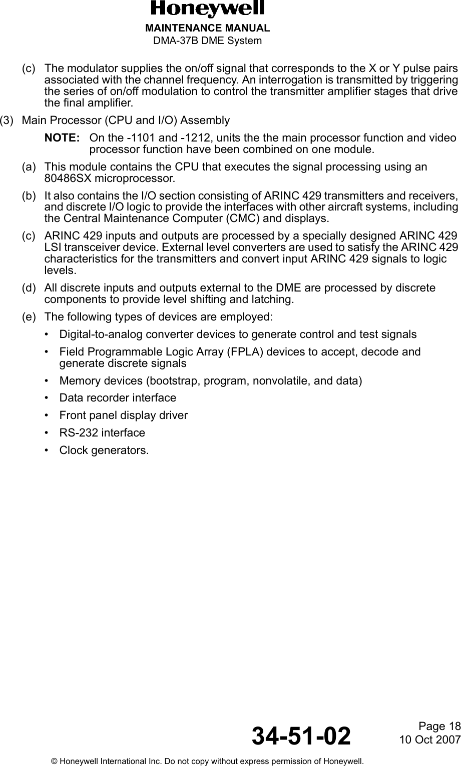
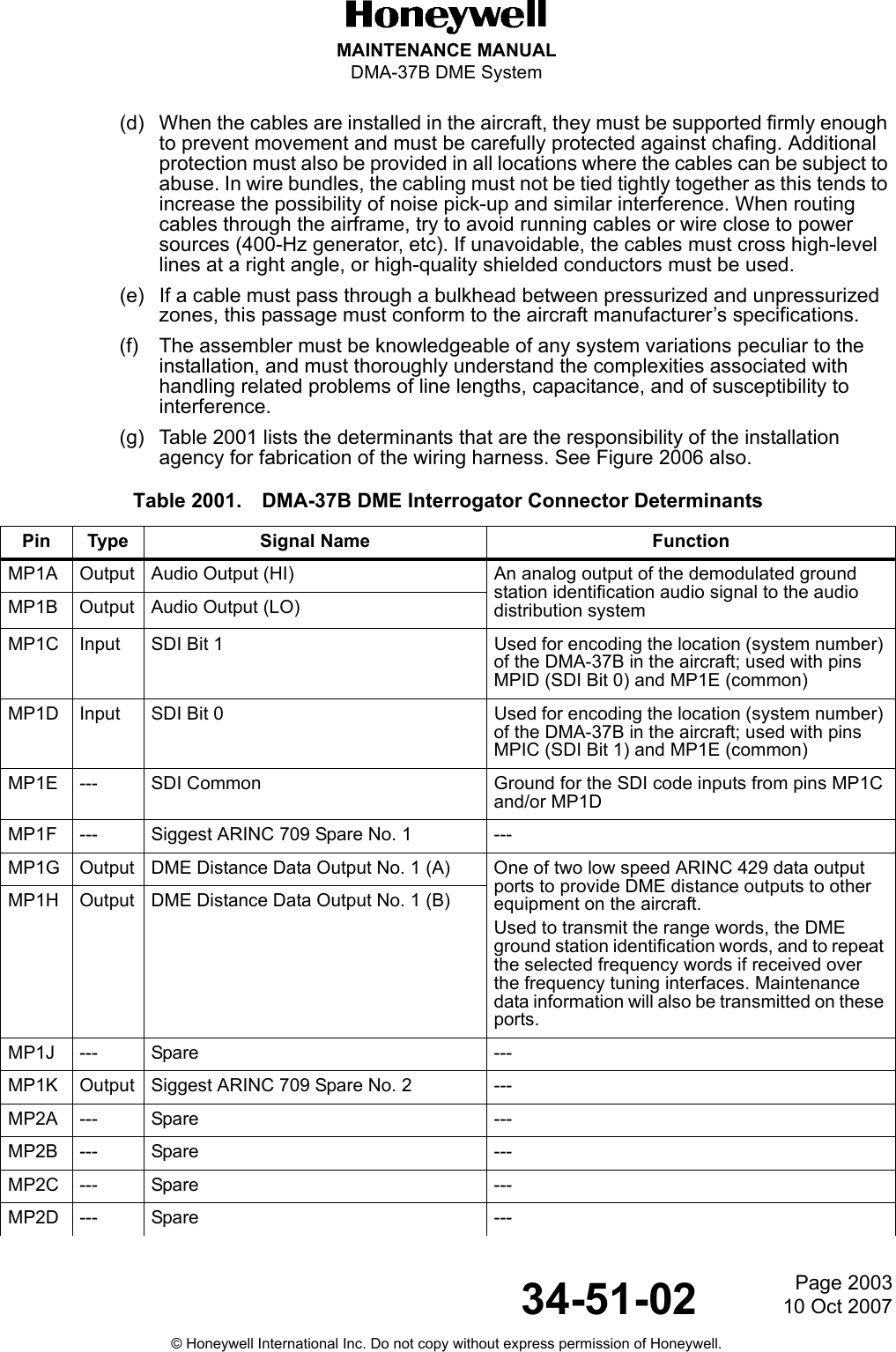
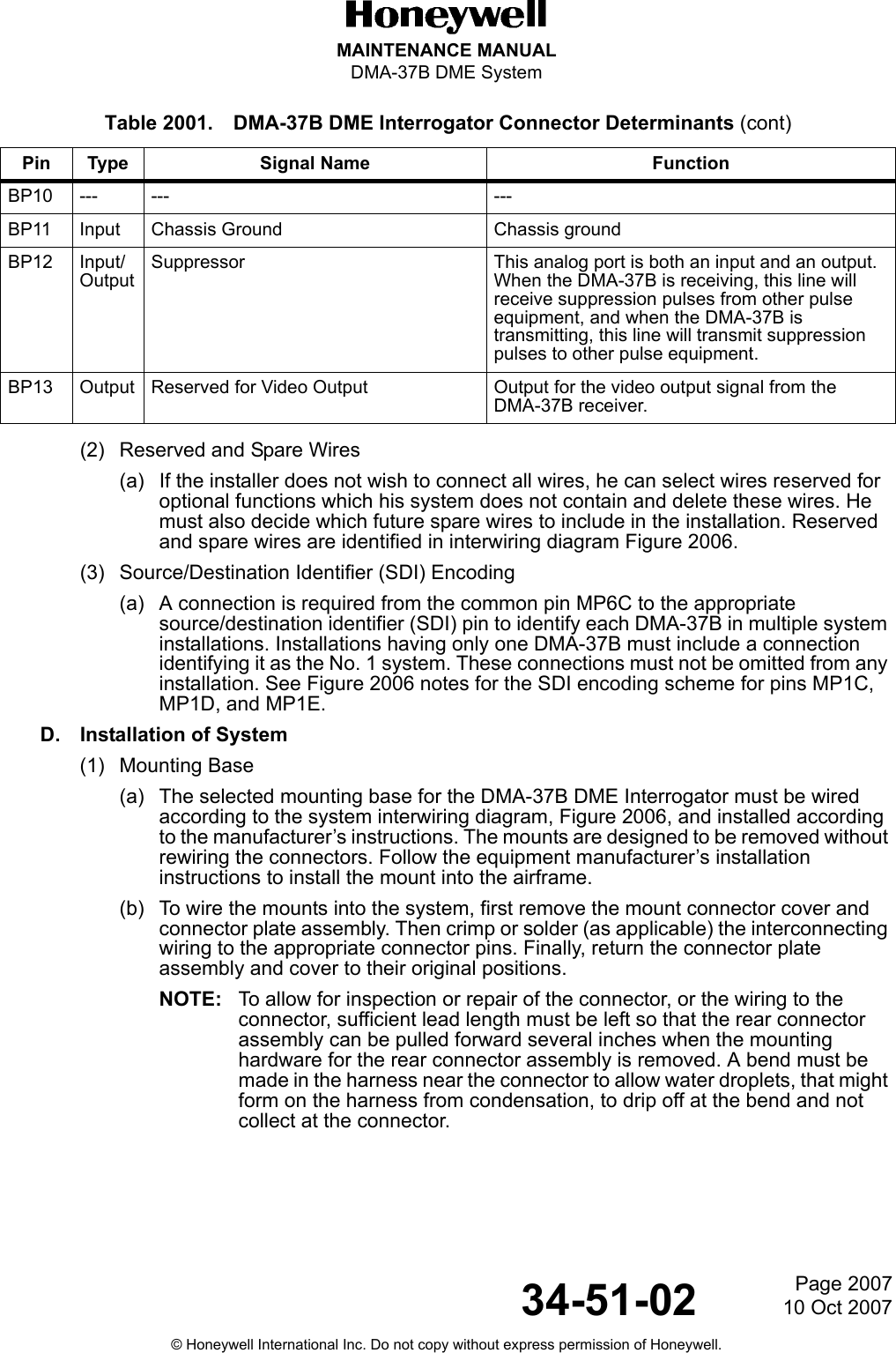
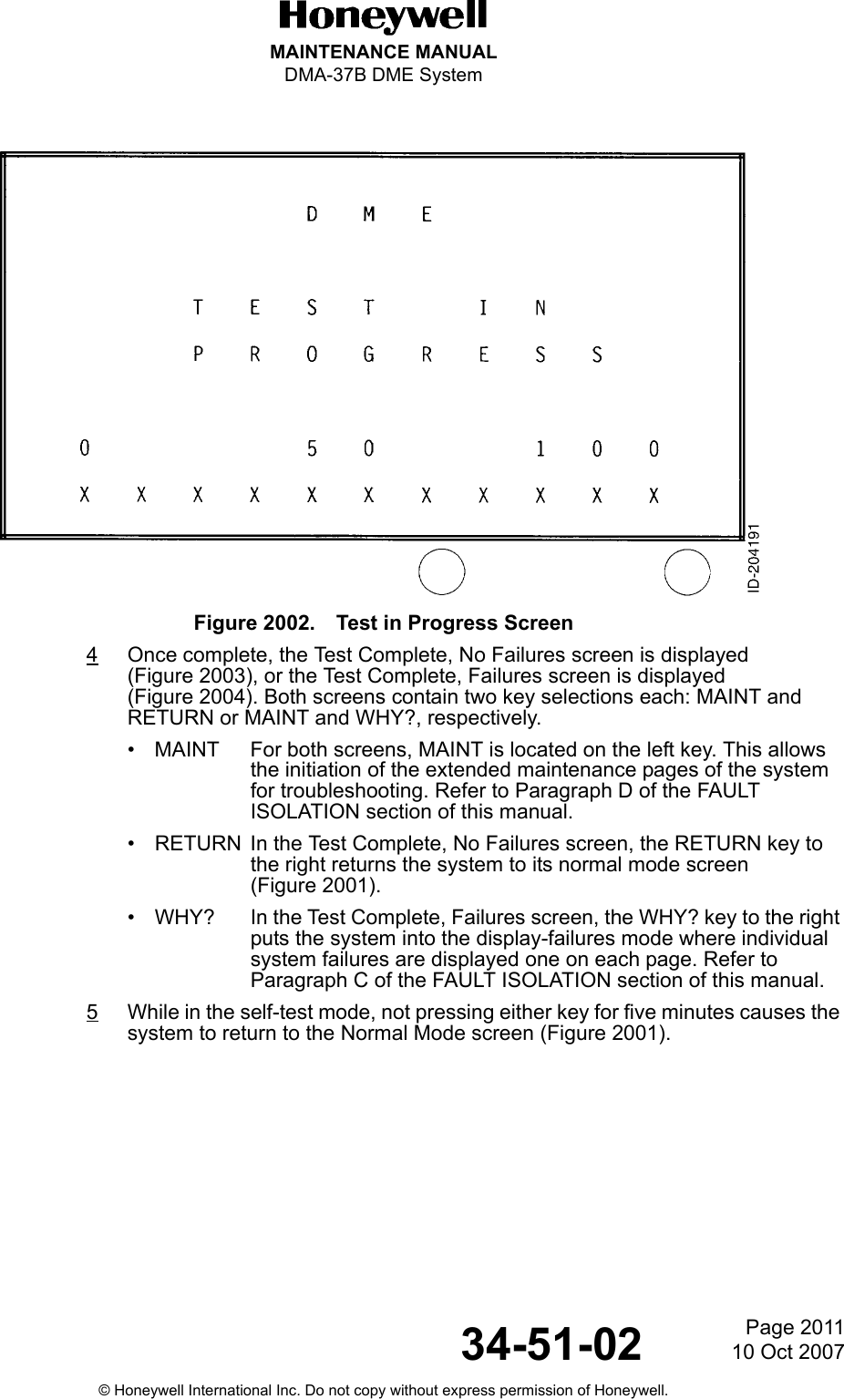
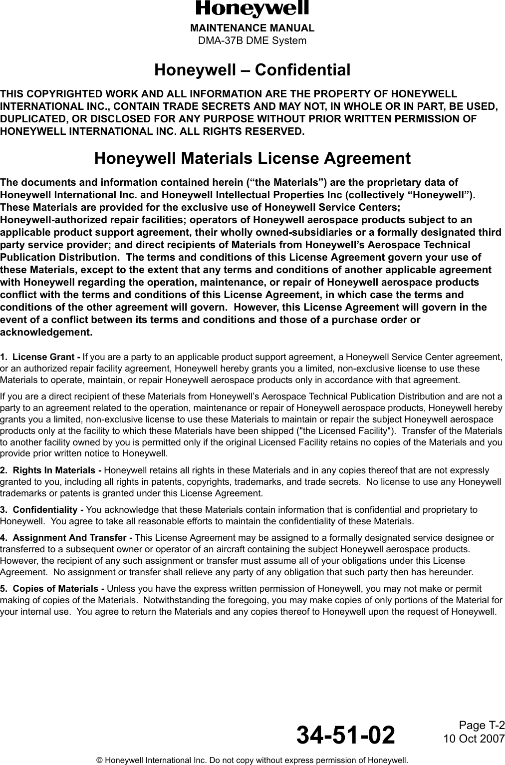
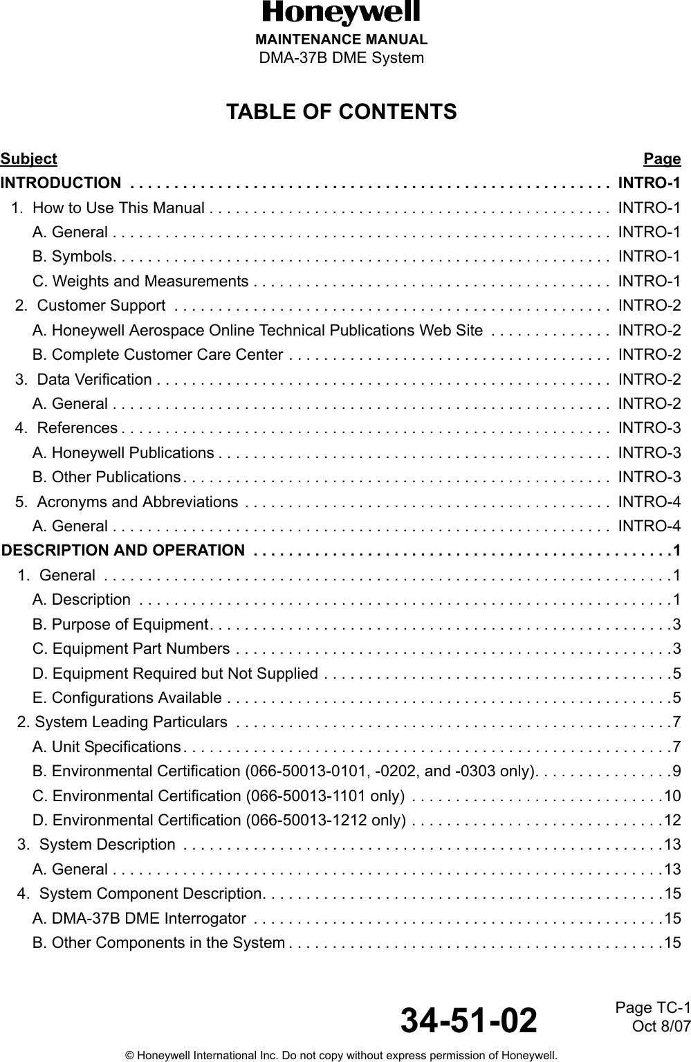
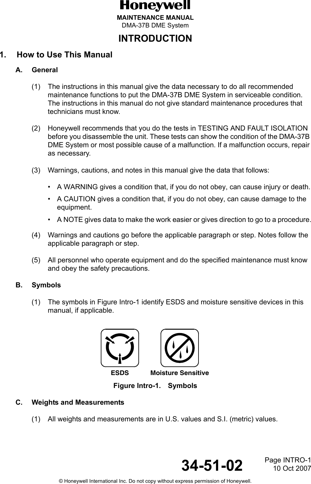
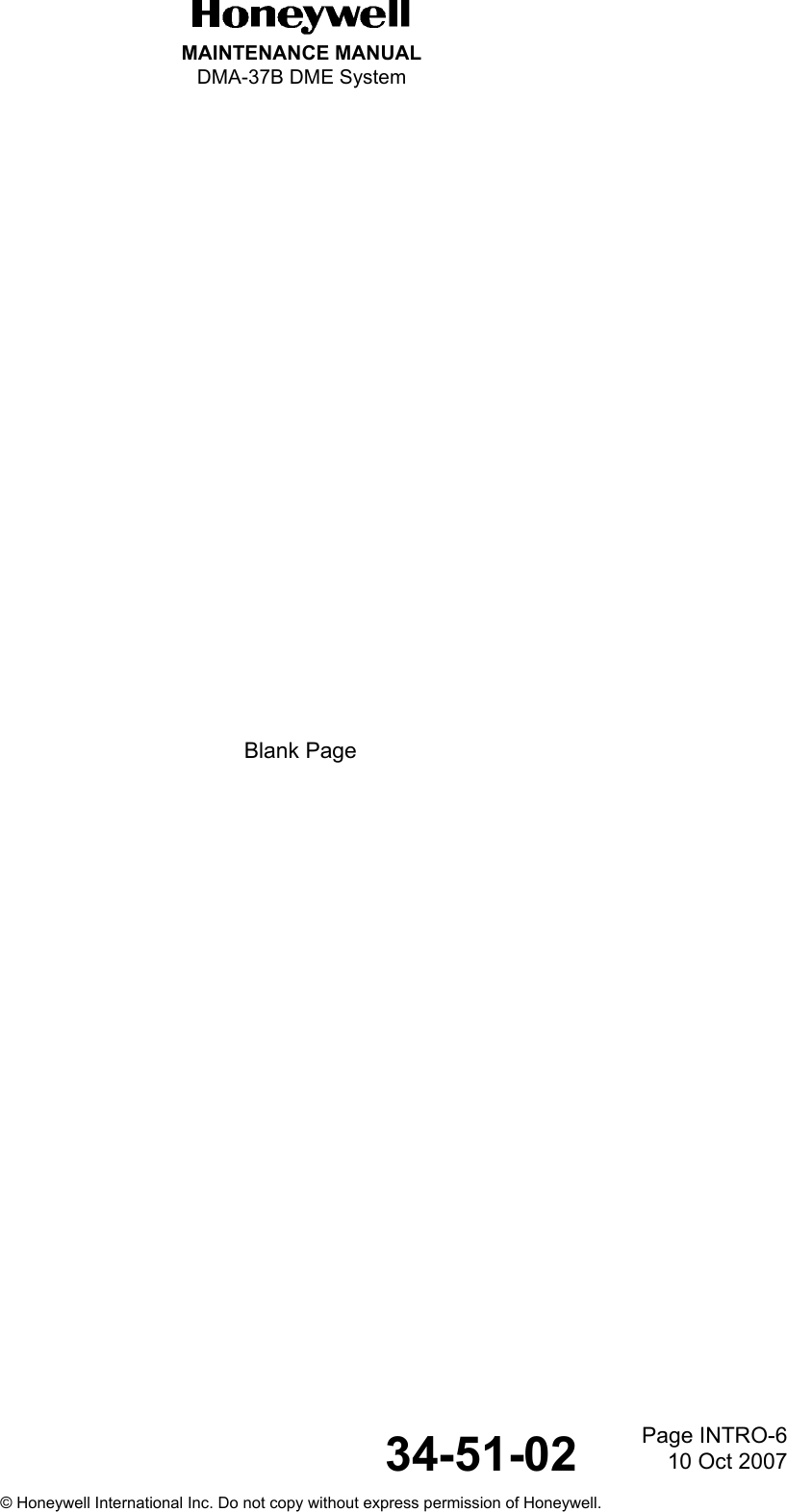
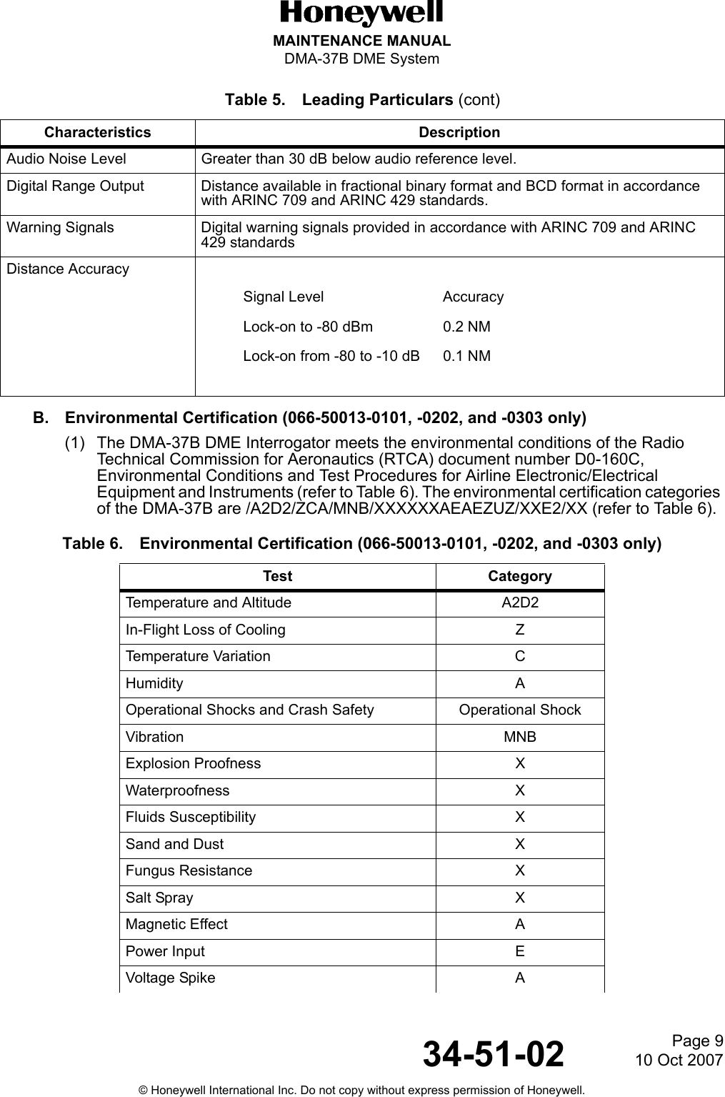
![Page 810 Oct 200734-51-02MAINTENANCE MANUALDMA-37B DME System© Honeywell International Inc. Do not copy without express permission of Honeywell.• -1212 TSO C66cDO-160E Environmental Category[(A2)(D2)Z]BAB[SB]XXXXXXAA(WF)HA[R(WF)][ZW]R[RR]L[ZZZZ]XXACICAO Annex 10 FM ImmunityDO-189, DO-178BTransmitterFrequency Range 1025.00 MHz to 1150.00 MHz, 1MHz channel spacingFrequency Stability ± 80 kHzPower Output 700 Watts, TypicalPulse Code Spacing• X-Channel 12.0 ± 0.4 microseconds• Y-Channel 36.0 ± 0.4 microsecondsFrequency Spectrum 90% of total pulse energy within ± 0.25 MHz of channel frequencyRise Time (maximum) 2.8 Microseconds (consistent with pulse spectrum)CW Leakage at Antenna Connector-79 dBm maximumAntenna Mismatch No damage to transmitter with antenna open or short circuitReceiverFrequency 962.00 MHz to 1213 MHz (252 Channels)Sensitivity -90 dBm minimum lock-on levelSelectivityDynamic Range 80 dB minimumImage Rejection 60 dB minimumCW Rejection 60 dB minimumAudio Output Capable of 40 milliwatts minimum into a 200-ohm to 10,000 ohm resistive load with -87 dBm input signal level.Harmonic Distortion Less than 15% with 1000 microvolts modulated 30% at 1000 Hz and less than 20% with 90% modulation for rated audio output into a 200-ohm to 600-ohm resistive loadAudio Output Regulation Less than 6-dB voltage change from a 25-milliwatt reference level into 200 ohms for resistive load variations of 200 ohms to 10,000 ohmsLess than 0.31-dB voltage change from a 40-milliwatt level into 600-ohm reference for resistive load variations of 453 ohms to 2400 ohms.Table 5. Leading Particulars (cont)Characteristics DescriptionAttenuation BandwidthLess than 6 dB 95 kHzMore than 50 dB ±800 kHz](https://usermanual.wiki/Honeywell/DMA-37B2/User-Guide-886120-Page-30.png)
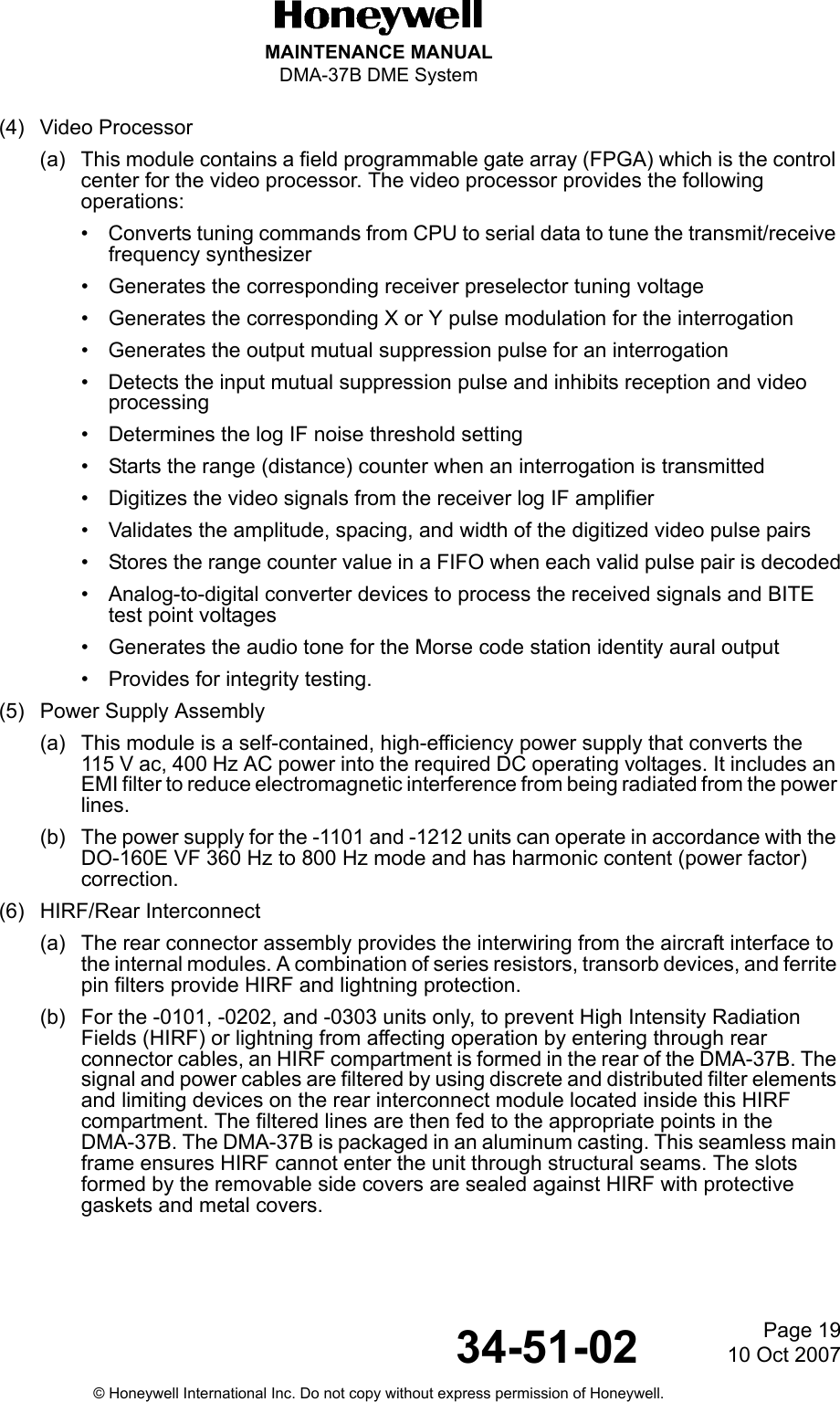
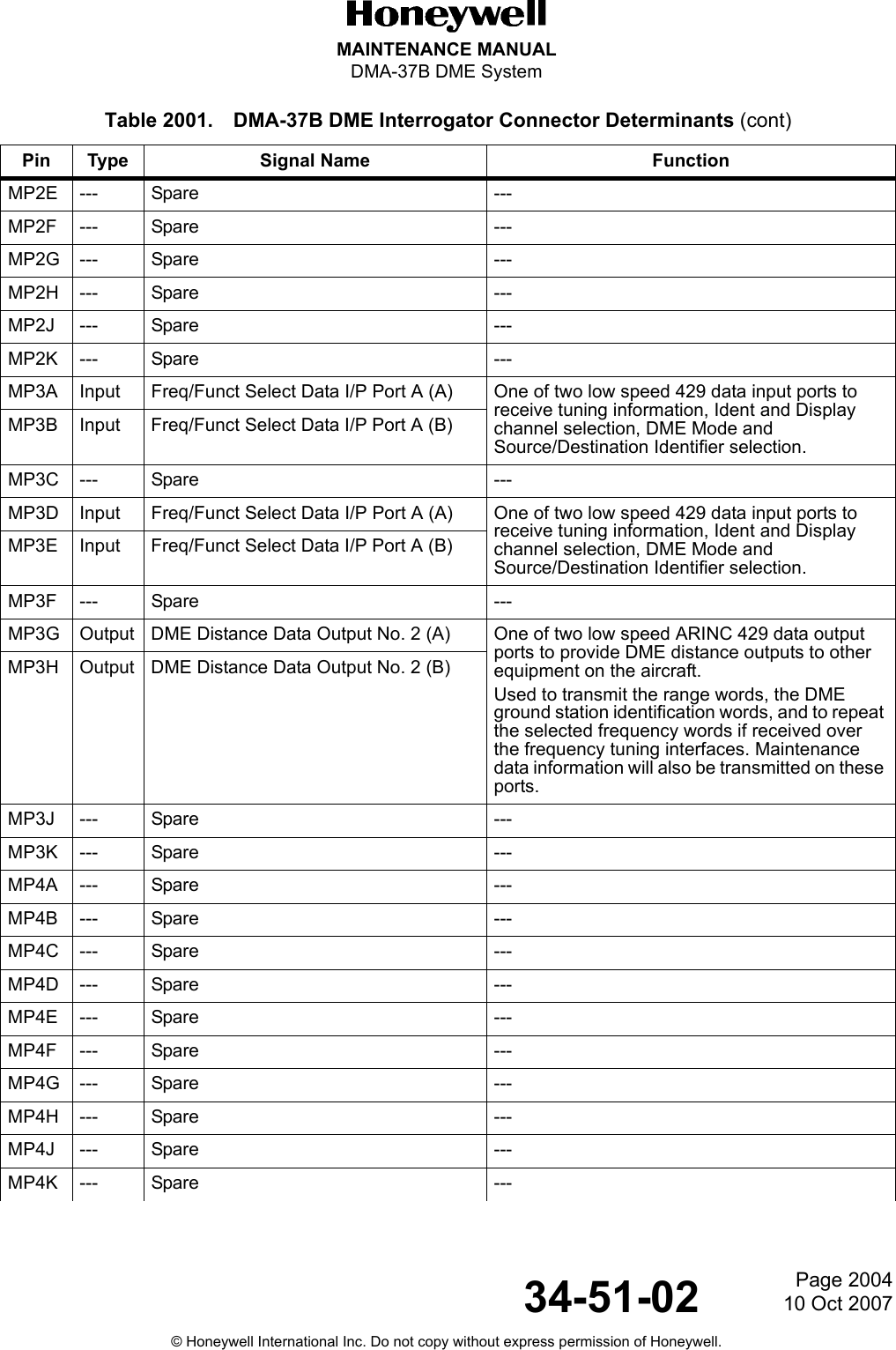
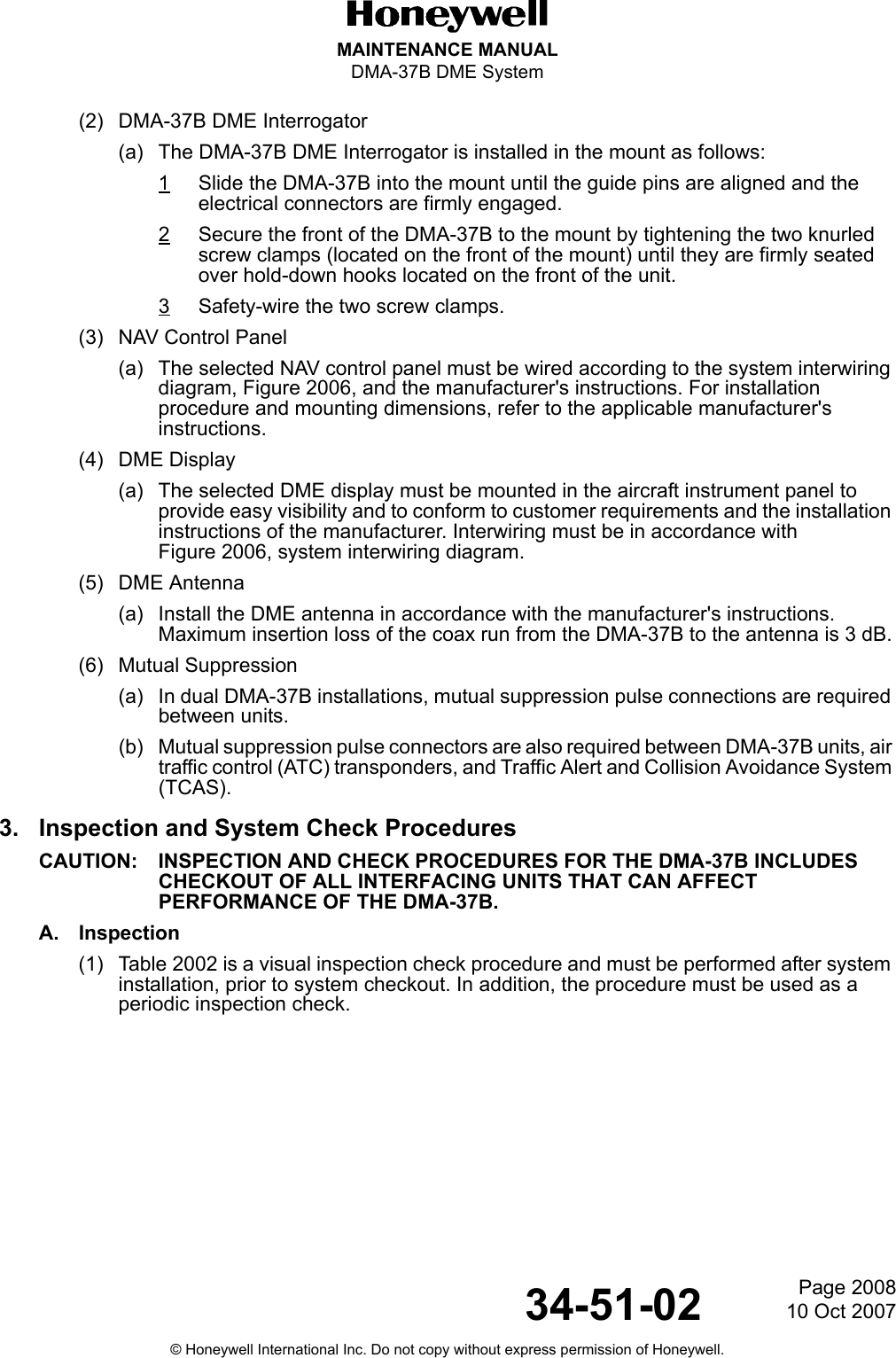
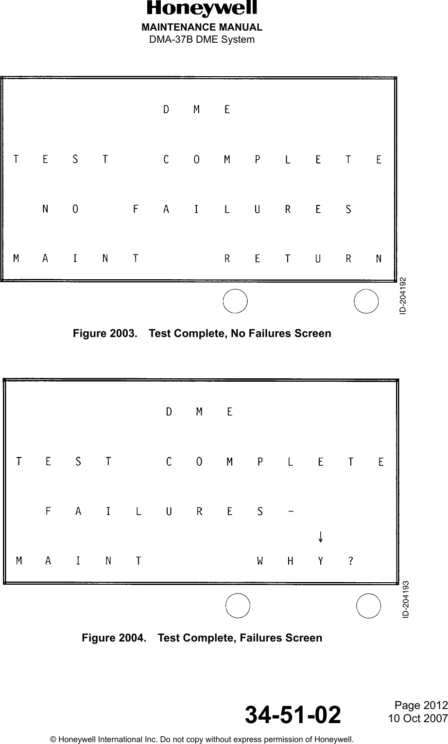
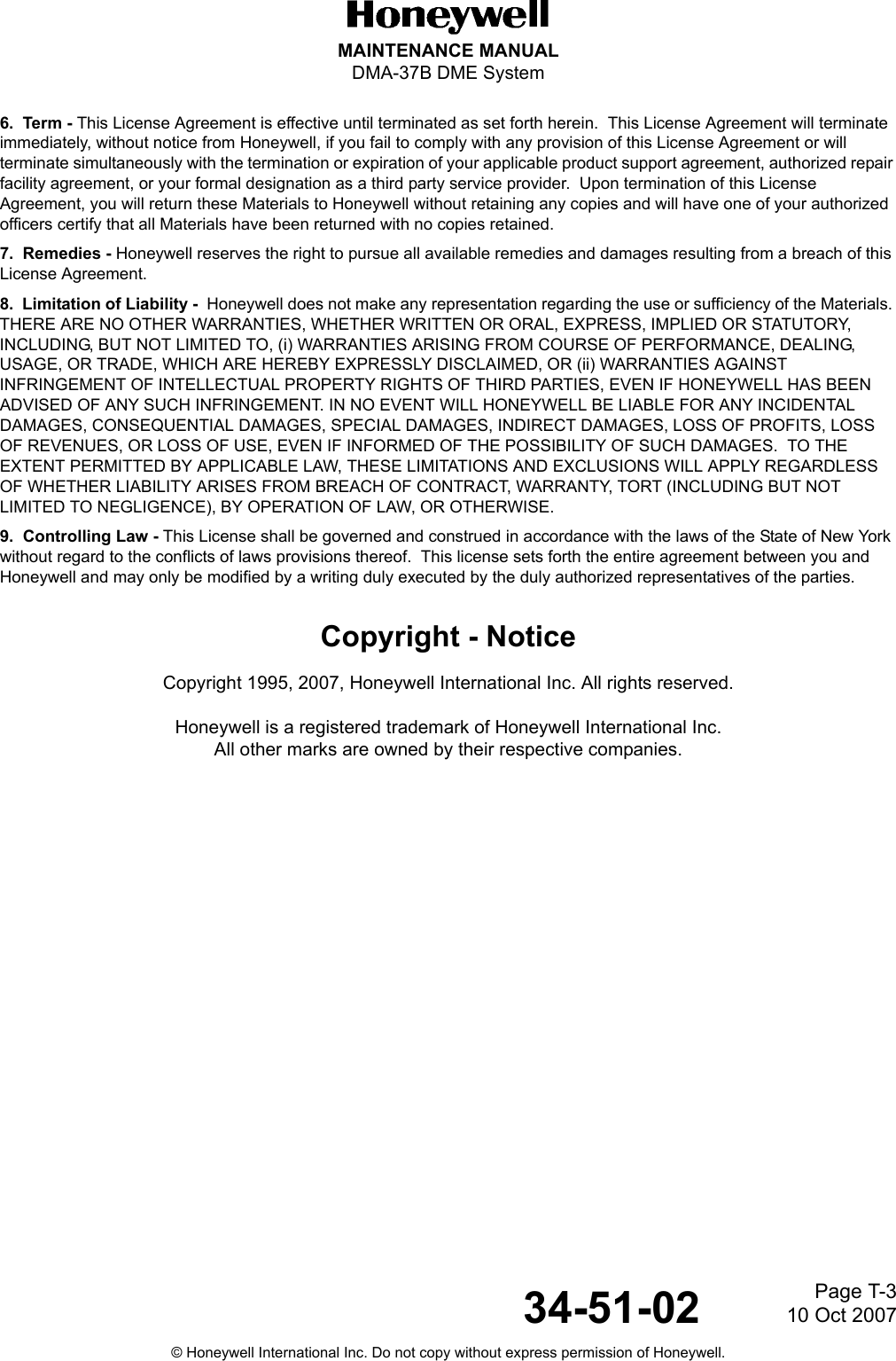
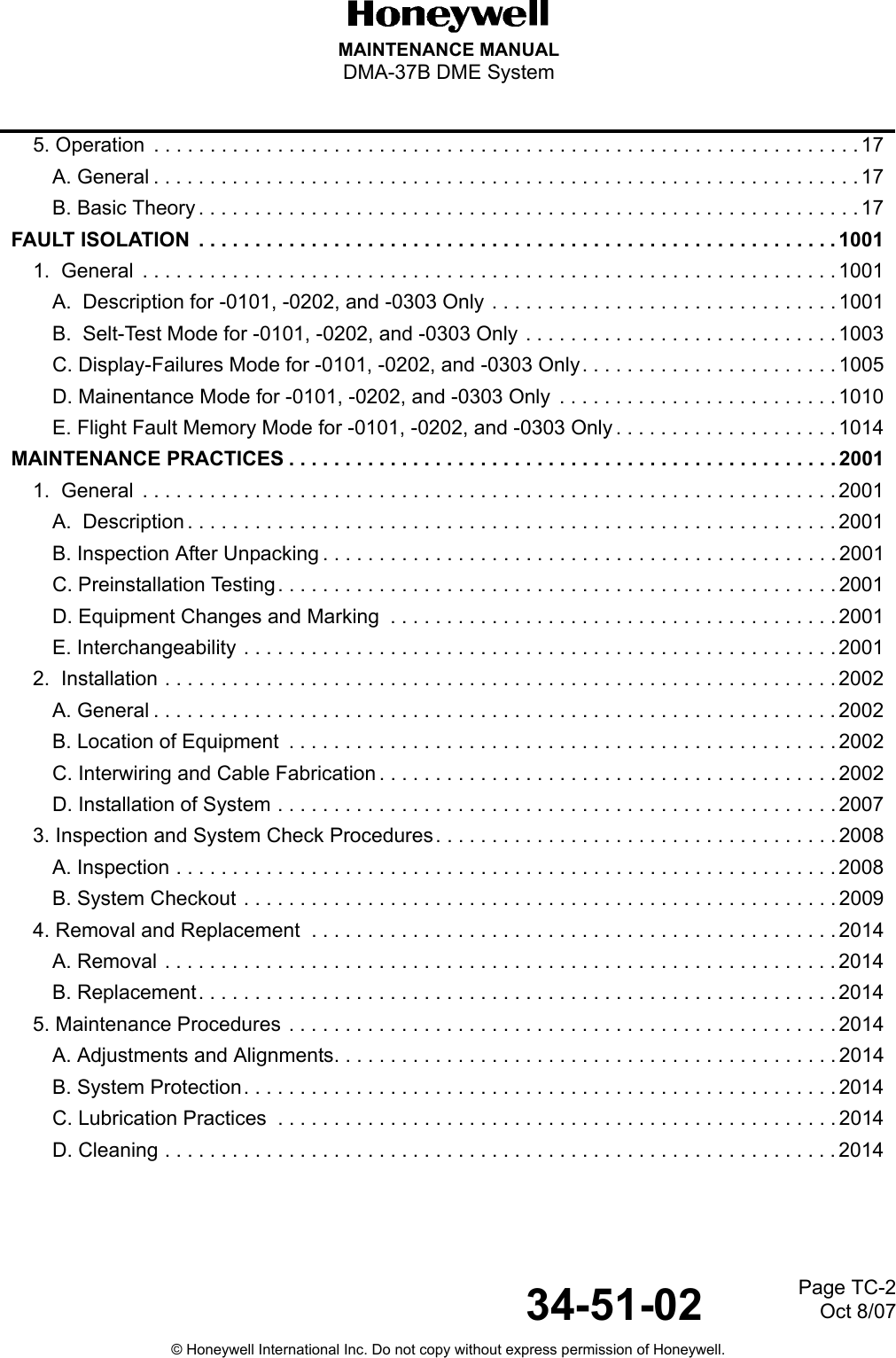
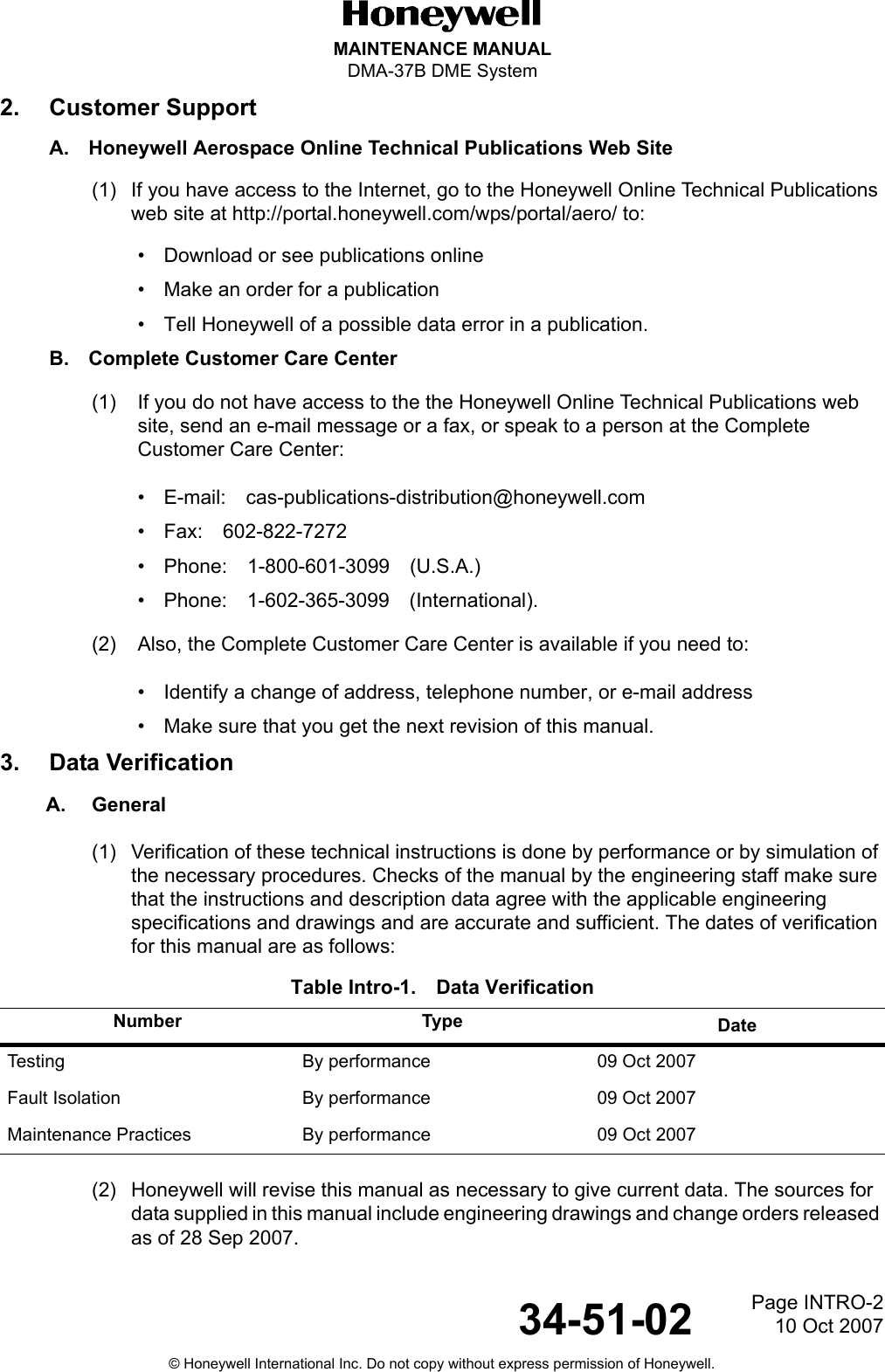
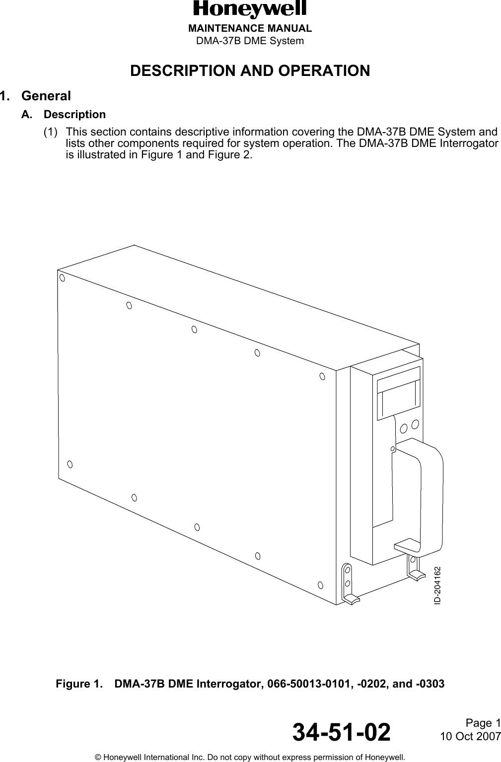
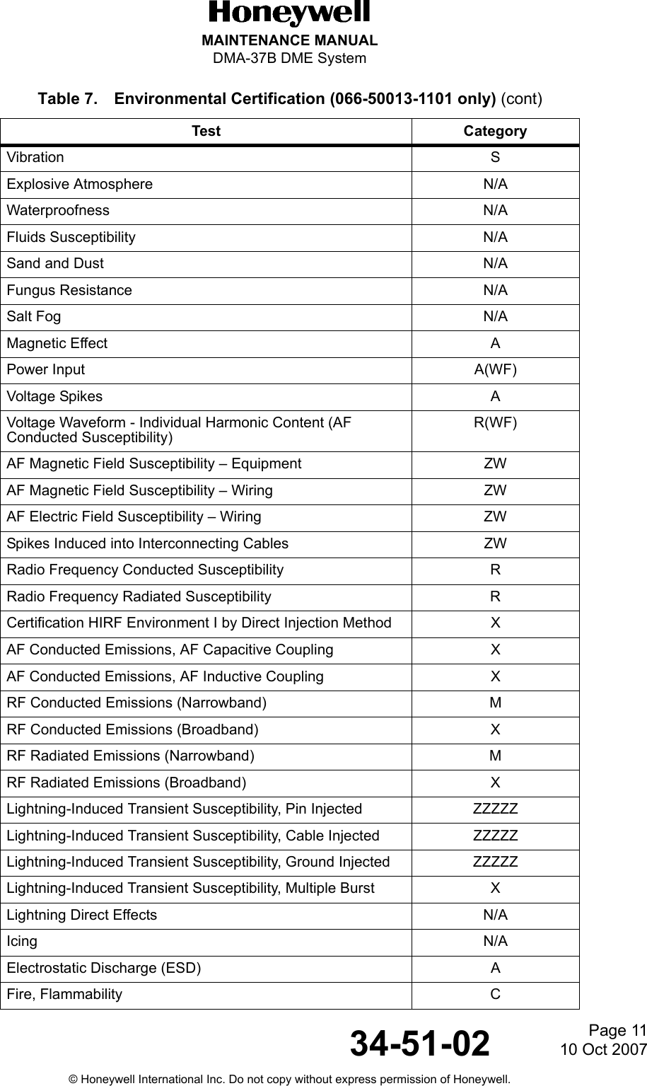
![Page 1010 Oct 200734-51-02MAINTENANCE MANUALDMA-37B DME System© Honeywell International Inc. Do not copy without express permission of Honeywell.C. Environmental Certification (066-50013-1101 only)(1) The DMA-37B DME Interrogator meets environmental conditions of RTCA document number DO-160E In addition to several Boeing Specific requirements (refer to Table 7). The environmental certification categories for the -1101 DMA-37B DME Interrogator are [(A2)(B2)V]BAB[SB]XXXXXXAA(WF)XA[R(WF)][ZW]RRRL[ZZZZ]XXAC (refer to Table 7).Audio Frequency Conducted Susceptibility - Power InputsEInduced Signal Susceptibility ZRadio Frequency Susceptibility(Radiated and Conducted)UEmission of Radio Frequency Energy ZLightning-Induced Transient Susceptibility XXE2Lightning-Direct Effects XIcing XTable 7. Environmental Certification (066-50013-1101 only)Test CategoryGround Survival Low Temperature A2 Short Term Operating Low Temperature A2 Operating Low Temperature A2 Ground Survival High Temperature A2 Short Term Operating High Temperature A2 Operating High Temperature A2 In-Flight Loss of Cooling V Altitude B2 Decompression A2 Overpressure A2 Temperature Variation B Humidity A Acceleration XVibration Due to Fan Blade Loss (Windmilling) XBench Handling Shock XShipping Container XOperational Shock (Emergency Landing and Bird Strike) B Table 6. Environmental Certification (066-50013-0101, -0202, and -0303 only) (cont)Test Category](https://usermanual.wiki/Honeywell/DMA-37B2/User-Guide-886120-Page-32.png)
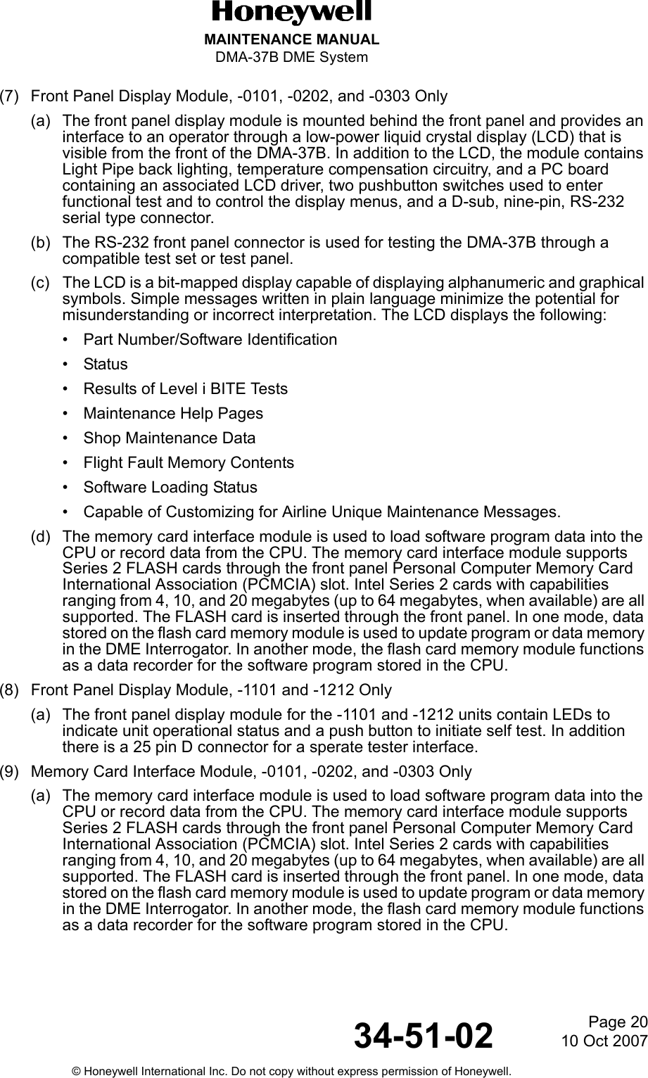
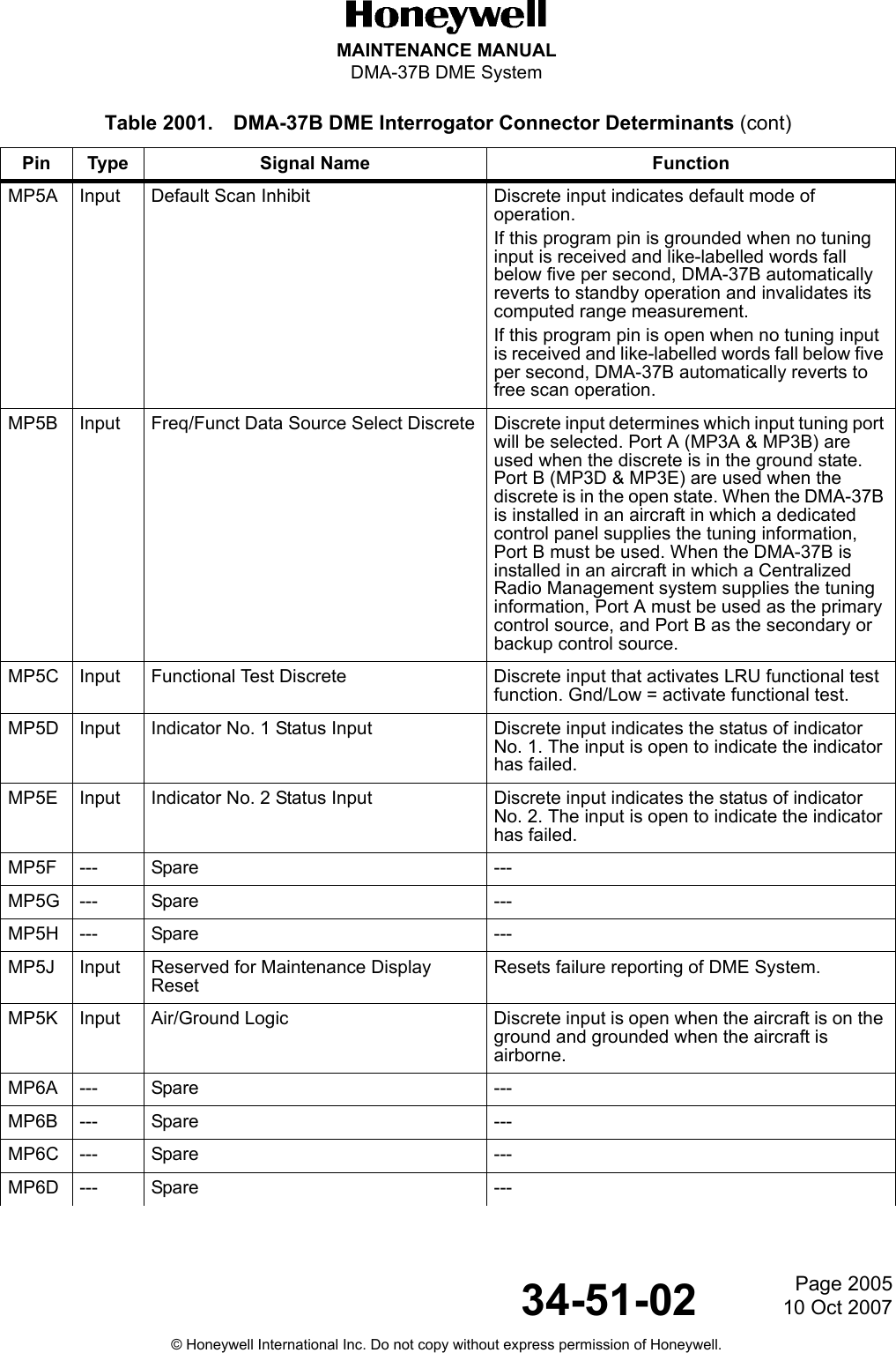
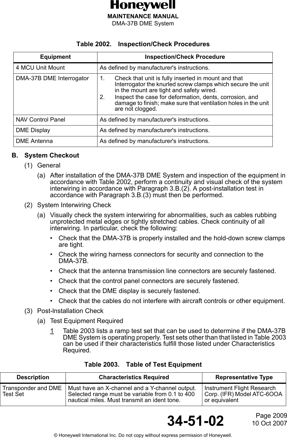
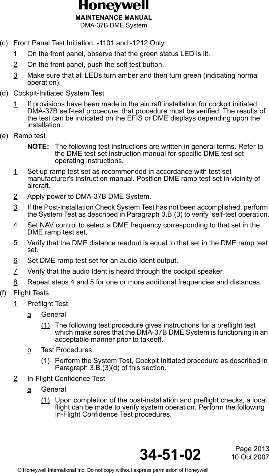
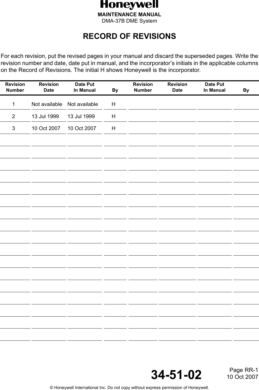
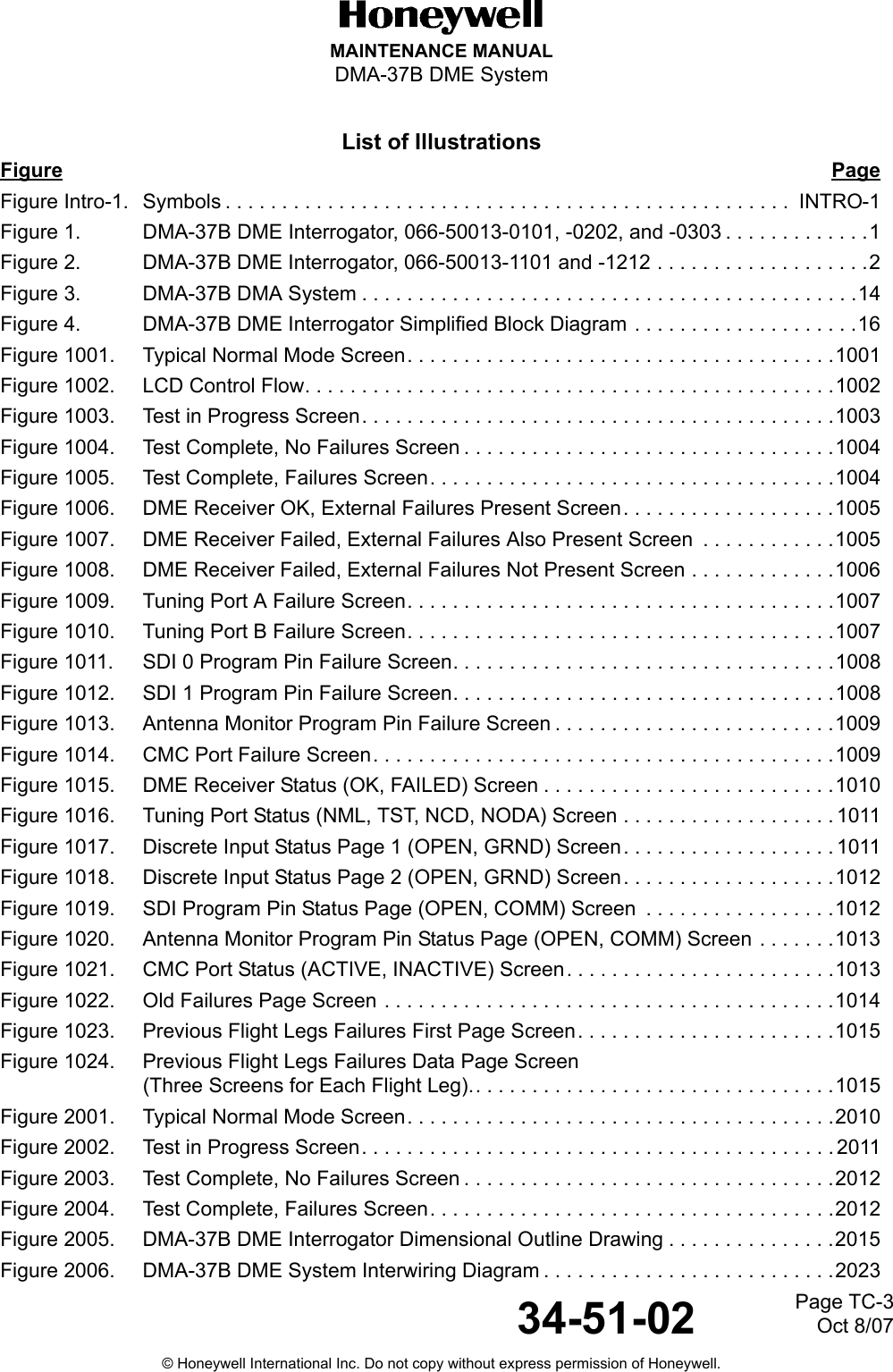
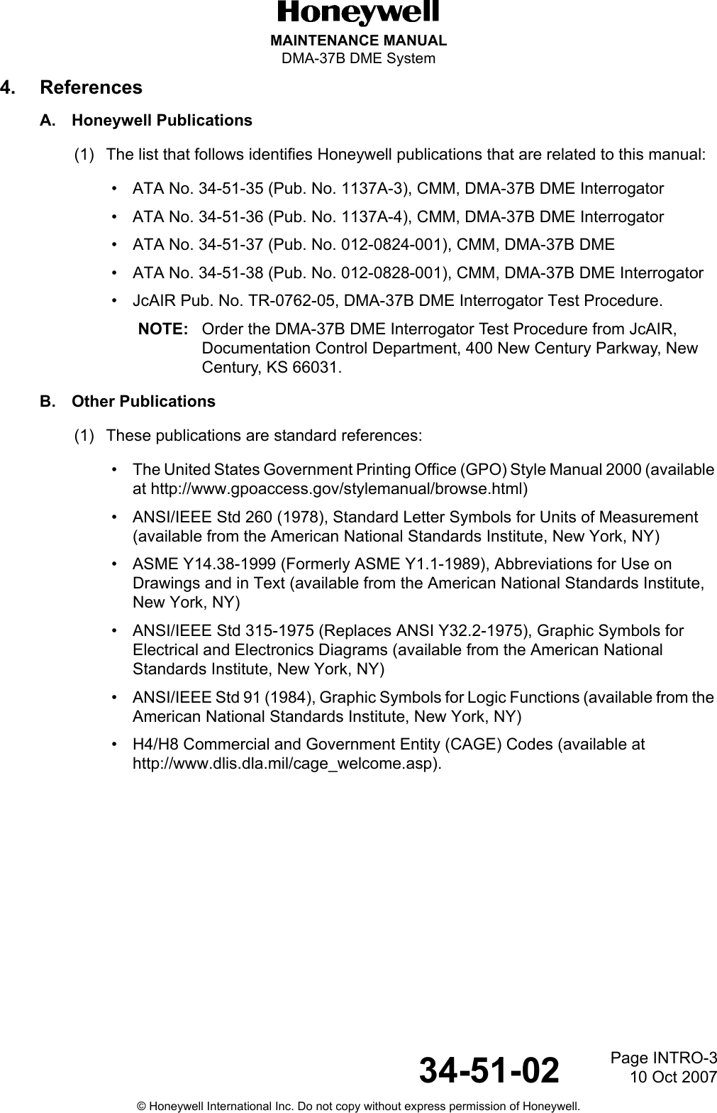
![Page 1210 Oct 200734-51-02MAINTENANCE MANUALDMA-37B DME System© Honeywell International Inc. Do not copy without express permission of Honeywell.D. Environmental Certification (066-50013-1212 only)(1) The DMA-37B DME Interrogator meets environmental conditions of RTCA document number DO-160E In addition to several Boeing Specific requirements (refer to Table 8). The environmental certification categories for the -1212 DMA-37B DME Interrogator are [(A2)(D2)Z]BAB[SB]XXXXXXAA(WF)HA[R(WF)][ZW]R[RR]L[ZZZZ]XXAC (refer to Table 8).Table 8. Environmental Certification (066-50013-1212 only)Test CategoryTemperature Test A2 In-Flight Loss of Cooling Z Temperature Variation B Altitude Test D2 Decompression Test A2 Overpressure Test A2 Humidity A Operational Shock And Crash Safety B Vibration S Vibration Due to Fan Blade Loss (Windmilling) XVibration: Due to Landing Gear Tyre Burst XExplosive Atmosphere XWaterproofness XFluids Susceptibility XSand and Dust XFungus Resistance XSalt Fog XMagnetic Effect A Power Input A (WF) Voltage Spike A Audio Frequency Conducted Susceptibility R(WF) AF Electric Field Susceptibility – Wiring ZW AF Magnetic Field Susceptibility – Wiring ZW AF Magnetic Field Susceptibility – Equipment ZW Spikes Induced into Interconnecting Cables ZW Radio Frequency Conducted Susceptibility R Radio Frequency Radiated Susceptibility R](https://usermanual.wiki/Honeywell/DMA-37B2/User-Guide-886120-Page-34.png)