Honeywell DMA-37B2 DMA-37B DME Interrogator, 066-50013-1101, -1212 User Manual MM DME 37B DME System 1137 1 Rev 3
Honeywell International Inc. DMA-37B DME Interrogator, 066-50013-1101, -1212 MM DME 37B DME System 1137 1 Rev 3
Users Manual

Page HL-1
10 Oct 2007
34-51-02 HIGHLIGHTS
© Honeywell International Inc. Do not copy without express permission of Honeywell.
Honeywell International Inc.
P.O. Box 97001
Redmond, Washington 98073-9701
U.S.A
CAGE 97896
Telephone: (800) 601-3099 (U.S.A.)
Telephone: (602) 365-3099 (International)
Web site: http://portal.honeywell.com/wps/portal/aero
TO HOLDERS OF MAINTENANCE MANUAL, PUB NO. 1137-1, DMA-37B DME SYSTEM
REVISION NO. 003 DATED 10 OCT 2007
HIGHLIGHTS
This revision is a full replacement. All changed pages have a new date, as identified in the List of
Effective Pages. Revision bars are not used because the structure has changed.
Remove and discard all pages of the manual and replace them with the attached pages. The Record
of Revisions page has been brought up-to-date for you.
Remove Page Insert Page Description of Change
--- --- Revised the header and footer on all pages.
T-1, PN-1 T-1 thru T-4 Revised to show the revision date of this manual. Added the ECCN
number. Replaced the proprietary notice with the new Honeywell
confidentiality notice, Materials License Agreement, and Copyright
Notice.
RH-1/RH-2 --- Deleted REVISION HIGHLIGHTS.
RR-1, RR-2 RR-1, RR-2 Revised and issued this section.
--- RTR-1, RTR-2 Added RECORD OF TEMPORARY REVISIONS.
LEP-1, LEP-2 LEP-1, LEP-2 Revised to show where changes are made in this manual.
TC-1/TC-2 TC-1 thru TC-4 Revised to show the location of the data in this manual.
INTRO-1 INTRO-1 thru
INTRO-6
Revised format. Added proprietary, export, precautionary, and content
data.
0 thru 21/22 1 thru 20 Revised and issued this section.
101 thru 116 1001 thru 1016 Revised and issued this section.
201 thru 226 2001 thru 2024 Revised and issued this section.

Page HL-2
10 Oct 2007
MAINTENANCE MANUAL
DMA-37B DME System
© Honeywell International Inc. Do not copy without express permission of Honeywell.
34-51-02
Blank Page

Honeywell International Inc.
P.O. Box 97001
Redmond, Washington 98073
U.S.A.
CAGE: 97896
Telephone: (800) 601-3099 (U.S.A.)
Telephone: (602) 365-3099 (International)
Web site: http://portal.honeywell.com/wps/portal/aero
Page T-1
Publication Number 1137-1, Revision 003 Revised 10 Oct 2007
Oct 1995
© Honeywell International Inc. Do not copy without express permission of Honeywell.
34-51-02
This document contains technical data and is subject to U.S. export regulations. These commodities,
technology, or software were exported from the United States in accordance with the export administration
regulations. Diversion contrary to U.S. law is prohibited.
ECCN: 7E994, no license required.
Maintenance Manual
DMA-37B DME System

Page T-2
10 Oct 2007
34-51-02
MAINTENANCE MANUAL
DMA-37B DME System
© Honeywell International Inc. Do not copy without express permission of Honeywell.
Honeywell – Confidential
THIS COPYRIGHTED WORK AND ALL INFORMATION ARE THE PROPERTY OF HONEYWELL
INTERNATIONAL INC., CONTAIN TRADE SECRETS AND MAY NOT, IN WHOLE OR IN PART, BE USED,
DUPLICATED, OR DISCLOSED FOR ANY PURPOSE WITHOUT PRIOR WRITTEN PERMISSION OF
HONEYWELL INTERNATIONAL INC. ALL RIGHTS RESERVED.
Honeywell Materials License Agreement
The documents and information contained herein (“the Materials”) are the proprietary data of
Honeywell International Inc. and Honeywell Intellectual Properties Inc (collectively “Honeywell”).
These Materials are provided for the exclusive use of Honeywell Service Centers;
Honeywell-authorized repair facilities; operators of Honeywell aerospace products subject to an
applicable product support agreement, their wholly owned-subsidiaries or a formally designated third
party service provider; and direct recipients of Materials from Honeywell’s Aerospace Technical
Publication Distribution. The terms and conditions of this License Agreement govern your use of
these Materials, except to the extent that any terms and conditions of another applicable agreement
with Honeywell regarding the operation, maintenance, or repair of Honeywell aerospace products
conflict with the terms and conditions of this License Agreement, in which case the terms and
conditions of the other agreement will govern. However, this License Agreement will govern in the
event of a conflict between its terms and conditions and those of a purchase order or
acknowledgement.
1. License Grant - If you are a party to an applicable product support agreement, a Honeywell Service Center agreement,
or an authorized repair facility agreement, Honeywell hereby grants you a limited, non-exclusive license to use these
Materials to operate, maintain, or repair Honeywell aerospace products only in accordance with that agreement.
If you are a direct recipient of these Materials from Honeywell’s Aerospace Technical Publication Distribution and are not a
party to an agreement related to the operation, maintenance or repair of Honeywell aerospace products, Honeywell hereby
grants you a limited, non-exclusive license to use these Materials to maintain or repair the subject Honeywell aerospace
products only at the facility to which these Materials have been shipped ("the Licensed Facility"). Transfer of the Materials
to another facility owned by you is permitted only if the original Licensed Facility retains no copies of the Materials and you
provide prior written notice to Honeywell.
2. Rights In Materials - Honeywell retains all rights in these Materials and in any copies thereof that are not expressly
granted to you, including all rights in patents, copyrights, trademarks, and trade secrets. No license to use any Honeywell
trademarks or patents is granted under this License Agreement.
3. Confidentiality - You acknowledge that these Materials contain information that is confidential and proprietary to
Honeywell. You agree to take all reasonable efforts to maintain the confidentiality of these Materials.
4. Assignment And Transfer - This License Agreement may be assigned to a formally designated service designee or
transferred to a subsequent owner or operator of an aircraft containing the subject Honeywell aerospace products.
However, the recipient of any such assignment or transfer must assume all of your obligations under this License
Agreement. No assignment or transfer shall relieve any party of any obligation that such party then has hereunder.
5. Copies of Materials - Unless you have the express written permission of Honeywell, you may not make or permit
making of copies of the Materials. Notwithstanding the foregoing, you may make copies of only portions of the Material for
your internal use. You agree to return the Materials and any copies thereof to Honeywell upon the request of Honeywell.

Page T-3
10 Oct 2007
34-51-02
MAINTENANCE MANUAL
DMA-37B DME System
© Honeywell International Inc. Do not copy without express permission of Honeywell.
6. Term - This License Agreement is effective until terminated as set forth herein. This License Agreement will terminate
immediately, without notice from Honeywell, if you fail to comply with any provision of this License Agreement or will
terminate simultaneously with the termination or expiration of your applicable product support agreement, authorized repair
facility agreement, or your formal designation as a third party service provider. Upon termination of this License
Agreement, you will return these Materials to Honeywell without retaining any copies and will have one of your authorized
officers certify that all Materials have been returned with no copies retained.
7. Remedies - Honeywell reserves the right to pursue all available remedies and damages resulting from a breach of this
License Agreement.
8. Limitation of Liability - Honeywell does not make any representation regarding the use or sufficiency of the Materials.
THERE ARE NO OTHER WARRANTIES, WHETHER WRITTEN OR ORAL, EXPRESS, IMPLIED OR STATUTORY,
INCLUDING, BUT NOT LIMITED TO, (i) WARRANTIES ARISING FROM COURSE OF PERFORMANCE, DEALING,
USAGE, OR TRADE, WHICH ARE HEREBY EXPRESSLY DISCLAIMED, OR (ii) WARRANTIES AGAINST
INFRINGEMENT OF INTELLECTUAL PROPERTY RIGHTS OF THIRD PARTIES, EVEN IF HONEYWELL HAS BEEN
ADVISED OF ANY SUCH INFRINGEMENT. IN NO EVENT WILL HONEYWELL BE LIABLE FOR ANY INCIDENTAL
DAMAGES, CONSEQUENTIAL DAMAGES, SPECIAL DAMAGES, INDIRECT DAMAGES, LOSS OF PROFITS, LOSS
OF REVENUES, OR LOSS OF USE, EVEN IF INFORMED OF THE POSSIBILITY OF SUCH DAMAGES. TO THE
EXTENT PERMITTED BY APPLICABLE LAW, THESE LIMITATIONS AND EXCLUSIONS WILL APPLY REGARDLESS
OF WHETHER LIABILITY ARISES FROM BREACH OF CONTRACT, WARRANTY, TORT (INCLUDING BUT NOT
LIMITED TO NEGLIGENCE), BY OPERATION OF LAW, OR OTHERWISE.
9. Controlling Law - This License shall be governed and construed in accordance with the laws of the State of New York
without regard to the conflicts of laws provisions thereof. This license sets forth the entire agreement between you and
Honeywell and may only be modified by a writing duly executed by the duly authorized representatives of the parties.
Copyright - Notice
Copyright 1995, 2007, Honeywell International Inc. All rights reserved.
Honeywell is a registered trademark of Honeywell International Inc.
All other marks are owned by their respective companies.

Page T-4
10 Oct 2007
34-51-02
MAINTENANCE MANUAL
DMA-37B DME System
© Honeywell International Inc. Do not copy without express permission of Honeywell.
Blank Page
Page RR-1
10 Oct 2007
34-51-02
MAINTENANCE MANUAL
DMA-37B DME System
© Honeywell International Inc. Do not copy without express permission of Honeywell.
RECORD OF REVISIONS
For each revision, put the revised pages in your manual and discard the superseded pages. Write the
revision number and date, date put in manual, and the incorporator’s initials in the applicable columns
on the Record of Revisions. The initial H shows Honeywell is the incorporator.
Revision
Number
Revision
Date
Date Put
In Manual By
Revision
Number
Revision
Date
Date Put
In Manual By
1 Not available Not available H
2 13 Jul 1999 13 Jul 1999 H
3 10 Oct 2007 10 Oct 2007 H

Page RR-2
10 Oct 2007
34-51-02
MAINTENANCE MANUAL
DMA-37B DME System
© Honeywell International Inc. Do not copy without express permission of Honeywell.
Revision
Number
Revision
Date
Date Put
In Manual By
Revision
Number
Revision
Date
Date Put
In Manual By
Page RTR-1
10 Oct 2007
34-51-02
MAINTENANCE MANUAL
DMA-37B DME System
© Honeywell International Inc. Do not copy without express permission of Honeywell.
RECORD OF TEMPORARY REVISIONS
Instructions on each page of a temporary revision tell you where to put the pages in your manual.
Remove temporary revision pages only when discard instructions are given. For each temporary
revision, put the applicable data in the record columns on this page.
Temporary
Revision
Number
Temporary
Revision
Date
Temporary
Revision
Status
Date Put in
Manual By
Date
Removed
From Manual By

Page RTR-2
10 Oct 2007
34-51-02
MAINTENANCE MANUAL
DMA-37B DME System
© Honeywell International Inc. Do not copy without express permission of Honeywell.
Temporary
Revision
Number
Temporary
Revision
Date
Temporary
Revision
Status
Date Put in
Manual By
Date
Removed
From Manual By

MAINTENANCE MANUAL
DMA-37B DME System
Page LEP-1
10 Oct 2007
© Honeywell International Inc. Do not copy without express permission of Honeywell.
34-51-02
indicates a changed or added page
F indicates a foldout page
LIST OF EFFECTIVE PAGES
Subheading and Page Date
Title 0
T-1 10 Oct 2007
T-2 10 Oct 2007
T-3 10 Oct 2007
T-4 10 Oct 2007
Record of Revisions 0
RR-1 10 Oct 2007
RR-2 10 Oct 2007
Record of Temporary Revisions 0
RTR-1 10 Oct 2007
RTR-2 10 Oct 2007
List of Effective Pages 0
LEP-1 10 Oct 2007
LEP-2 10 Oct 2007
Table of Contents 0
TC-1 10 Oct 2007
TC-2 10 Oct 2007
TC-3 10 Oct 2007
TC-4 10 Oct 2007
Introduction 0
INTRO-1 10 Oct 2007
INTRO-2 10 Oct 2007
INTRO-3 10 Oct 2007
INTRO-4 10 Oct 2007
INTRO-5 10 Oct 2007
INTRO-6 10 Oct 2007
Description and Operation 0
110 Oct 2007
210 Oct 2007
310 Oct 2007
410 Oct 2007
510 Oct 2007
610 Oct 2007
710 Oct 2007
810 Oct 2007
910 Oct 2007
10 10 Oct 2007
11 10 Oct 2007
12 10 Oct 2007
13 10 Oct 2007
14 10 Oct 2007
15 10 Oct 2007
16 10 Oct 2007
17 10 Oct 2007
18 10 Oct 2007
19 10 Oct 2007
20 10 Oct 2007
Fault Isolation 1000
1001 10 Oct 2007
1002 10 Oct 2007
1003 10 Oct 2007
1004 10 Oct 2007
1005 10 Oct 2007
1006 10 Oct 2007
1007 10 Oct 2007
1008 10 Oct 2007
1009 10 Oct 2007
1010 10 Oct 2007
1011 10 Oct 2007
1012 10 Oct 2007
1013 10 Oct 2007
1014 10 Oct 2007
1015 10 Oct 2007
1016 10 Oct 2007
Subheading and Page Date

MAINTENANCE MANUAL
DMA-37B DME System
Page LEP-2
10 Oct 2007
© Honeywell International Inc. Do not copy without express permission of Honeywell.
34-51-02
indicates a changed or added page
F indicates a foldout page
Maintenance Practices 2000
2001 10 Oct 2007
2002 10 Oct 2007
2003 10 Oct 2007
2004 10 Oct 2007
2005 10 Oct 2007
2006 10 Oct 2007
2007 10 Oct 2007
2008 10 Oct 2007
2009 10 Oct 2007
2010 10 Oct 2007
2011 10 Oct 2007
2012 10 Oct 2007
2013 10 Oct 2007
2014 10 Oct 2007
F 2015/2016 10 Oct 2007
F 2017/2018 10 Oct 2007
F 2019/2020 10 Oct 2007
F 2021/2022 10 Oct 2007
F 2023/2024 10 Oct 2007
Subheading and Page Date

Page TC-1
Oct 8/07
34-51-02
MAINTENANCE MANUAL
DMA-37B DME System
© Honeywell International Inc. Do not copy without express permission of Honeywell.
TABLE OF CONTENTS
Subject Page
INTRODUCTION . . . . . . . . . . . . . . . . . . . . . . . . . . . . . . . . . . . . . . . . . . . . . . . . . . . . . . . INTRO-1
1. How to Use This Manual . . . . . . . . . . . . . . . . . . . . . . . . . . . . . . . . . . . . . . . . . . . . . . INTRO-1
A. General . . . . . . . . . . . . . . . . . . . . . . . . . . . . . . . . . . . . . . . . . . . . . . . . . . . . . . . . . INTRO-1
B. Symbols. . . . . . . . . . . . . . . . . . . . . . . . . . . . . . . . . . . . . . . . . . . . . . . . . . . . . . . . . INTRO-1
C. Weights and Measurements . . . . . . . . . . . . . . . . . . . . . . . . . . . . . . . . . . . . . . . . . INTRO-1
2. Customer Support . . . . . . . . . . . . . . . . . . . . . . . . . . . . . . . . . . . . . . . . . . . . . . . . . . INTRO-2
A. Honeywell Aerospace Online Technical Publications Web Site . . . . . . . . . . . . . . INTRO-2
B. Complete Customer Care Center . . . . . . . . . . . . . . . . . . . . . . . . . . . . . . . . . . . . . INTRO-2
3. Data Verification . . . . . . . . . . . . . . . . . . . . . . . . . . . . . . . . . . . . . . . . . . . . . . . . . . . . INTRO-2
A. General . . . . . . . . . . . . . . . . . . . . . . . . . . . . . . . . . . . . . . . . . . . . . . . . . . . . . . . . . INTRO-2
4. References . . . . . . . . . . . . . . . . . . . . . . . . . . . . . . . . . . . . . . . . . . . . . . . . . . . . . . . . INTRO-3
A. Honeywell Publications . . . . . . . . . . . . . . . . . . . . . . . . . . . . . . . . . . . . . . . . . . . . . INTRO-3
B. Other Publications. . . . . . . . . . . . . . . . . . . . . . . . . . . . . . . . . . . . . . . . . . . . . . . . . INTRO-3
5. Acronyms and Abbreviations . . . . . . . . . . . . . . . . . . . . . . . . . . . . . . . . . . . . . . . . . . INTRO-4
A. General . . . . . . . . . . . . . . . . . . . . . . . . . . . . . . . . . . . . . . . . . . . . . . . . . . . . . . . . . INTRO-4
DESCRIPTION AND OPERATION . . . . . . . . . . . . . . . . . . . . . . . . . . . . . . . . . . . . . . . . . . . . . . . .1
1. General . . . . . . . . . . . . . . . . . . . . . . . . . . . . . . . . . . . . . . . . . . . . . . . . . . . . . . . . . . . . . . . . .1
A. Description . . . . . . . . . . . . . . . . . . . . . . . . . . . . . . . . . . . . . . . . . . . . . . . . . . . . . . . . . . . . .1
B. Purpose of Equipment. . . . . . . . . . . . . . . . . . . . . . . . . . . . . . . . . . . . . . . . . . . . . . . . . . . . .3
C. Equipment Part Numbers . . . . . . . . . . . . . . . . . . . . . . . . . . . . . . . . . . . . . . . . . . . . . . . . . .3
D. Equipment Required but Not Supplied . . . . . . . . . . . . . . . . . . . . . . . . . . . . . . . . . . . . . . . .5
E. Configurations Available . . . . . . . . . . . . . . . . . . . . . . . . . . . . . . . . . . . . . . . . . . . . . . . . . . .5
2. System Leading Particulars . . . . . . . . . . . . . . . . . . . . . . . . . . . . . . . . . . . . . . . . . . . . . . . . . .7
A. Unit Specifications. . . . . . . . . . . . . . . . . . . . . . . . . . . . . . . . . . . . . . . . . . . . . . . . . . . . . . . .7
B. Environmental Certification (066-50013-0101, -0202, and -0303 only). . . . . . . . . . . . . . . .9
C. Environmental Certification (066-50013-1101 only) . . . . . . . . . . . . . . . . . . . . . . . . . . . . .10
D. Environmental Certification (066-50013-1212 only) . . . . . . . . . . . . . . . . . . . . . . . . . . . . .12
3. System Description . . . . . . . . . . . . . . . . . . . . . . . . . . . . . . . . . . . . . . . . . . . . . . . . . . . . . . .13
A. General . . . . . . . . . . . . . . . . . . . . . . . . . . . . . . . . . . . . . . . . . . . . . . . . . . . . . . . . . . . . . . .13
4. System Component Description. . . . . . . . . . . . . . . . . . . . . . . . . . . . . . . . . . . . . . . . . . . . . .15
A. DMA-37B DME Interrogator . . . . . . . . . . . . . . . . . . . . . . . . . . . . . . . . . . . . . . . . . . . . . . .15
B. Other Components in the System . . . . . . . . . . . . . . . . . . . . . . . . . . . . . . . . . . . . . . . . . . .15

Page TC-2
Oct 8/07
34-51-02
MAINTENANCE MANUAL
DMA-37B DME System
© Honeywell International Inc. Do not copy without express permission of Honeywell.
5. Operation . . . . . . . . . . . . . . . . . . . . . . . . . . . . . . . . . . . . . . . . . . . . . . . . . . . . . . . . . . . . . . . 17
A. General . . . . . . . . . . . . . . . . . . . . . . . . . . . . . . . . . . . . . . . . . . . . . . . . . . . . . . . . . . . . . . . 17
B. Basic Theory . . . . . . . . . . . . . . . . . . . . . . . . . . . . . . . . . . . . . . . . . . . . . . . . . . . . . . . . . . . 17
FAULT ISOLATION . . . . . . . . . . . . . . . . . . . . . . . . . . . . . . . . . . . . . . . . . . . . . . . . . . . . . . . . . 1001
1. General . . . . . . . . . . . . . . . . . . . . . . . . . . . . . . . . . . . . . . . . . . . . . . . . . . . . . . . . . . . . . . 1001
A. Description for -0101, -0202, and -0303 Only . . . . . . . . . . . . . . . . . . . . . . . . . . . . . . . 1001
B. Selt-Test Mode for -0101, -0202, and -0303 Only . . . . . . . . . . . . . . . . . . . . . . . . . . . . 1003
C. Display-Failures Mode for -0101, -0202, and -0303 Only. . . . . . . . . . . . . . . . . . . . . . . 1005
D. Mainentance Mode for -0101, -0202, and -0303 Only . . . . . . . . . . . . . . . . . . . . . . . . . 1010
E. Flight Fault Memory Mode for -0101, -0202, and -0303 Only . . . . . . . . . . . . . . . . . . . . 1014
MAINTENANCE PRACTICES . . . . . . . . . . . . . . . . . . . . . . . . . . . . . . . . . . . . . . . . . . . . . . . . . 2001
1. General . . . . . . . . . . . . . . . . . . . . . . . . . . . . . . . . . . . . . . . . . . . . . . . . . . . . . . . . . . . . . . 2001
A. Description . . . . . . . . . . . . . . . . . . . . . . . . . . . . . . . . . . . . . . . . . . . . . . . . . . . . . . . . . . 2001
B. Inspection After Unpacking . . . . . . . . . . . . . . . . . . . . . . . . . . . . . . . . . . . . . . . . . . . . . . 2001
C. Preinstallation Testing. . . . . . . . . . . . . . . . . . . . . . . . . . . . . . . . . . . . . . . . . . . . . . . . . . 2001
D. Equipment Changes and Marking . . . . . . . . . . . . . . . . . . . . . . . . . . . . . . . . . . . . . . . . 2001
E. Interchangeability . . . . . . . . . . . . . . . . . . . . . . . . . . . . . . . . . . . . . . . . . . . . . . . . . . . . .2001
2. Installation . . . . . . . . . . . . . . . . . . . . . . . . . . . . . . . . . . . . . . . . . . . . . . . . . . . . . . . . . . . . 2002
A. General . . . . . . . . . . . . . . . . . . . . . . . . . . . . . . . . . . . . . . . . . . . . . . . . . . . . . . . . . . . . . 2002
B. Location of Equipment . . . . . . . . . . . . . . . . . . . . . . . . . . . . . . . . . . . . . . . . . . . . . . . . . 2002
C. Interwiring and Cable Fabrication . . . . . . . . . . . . . . . . . . . . . . . . . . . . . . . . . . . . . . . . . 2002
D. Installation of System . . . . . . . . . . . . . . . . . . . . . . . . . . . . . . . . . . . . . . . . . . . . . . . . . . 2007
3. Inspection and System Check Procedures. . . . . . . . . . . . . . . . . . . . . . . . . . . . . . . . . . . . 2008
A. Inspection . . . . . . . . . . . . . . . . . . . . . . . . . . . . . . . . . . . . . . . . . . . . . . . . . . . . . . . . . . . 2008
B. System Checkout . . . . . . . . . . . . . . . . . . . . . . . . . . . . . . . . . . . . . . . . . . . . . . . . . . . . . 2009
4. Removal and Replacement . . . . . . . . . . . . . . . . . . . . . . . . . . . . . . . . . . . . . . . . . . . . . . . 2014
A. Removal . . . . . . . . . . . . . . . . . . . . . . . . . . . . . . . . . . . . . . . . . . . . . . . . . . . . . . . . . . . . 2014
B. Replacement. . . . . . . . . . . . . . . . . . . . . . . . . . . . . . . . . . . . . . . . . . . . . . . . . . . . . . . . .2014
5. Maintenance Procedures . . . . . . . . . . . . . . . . . . . . . . . . . . . . . . . . . . . . . . . . . . . . . . . . . 2014
A. Adjustments and Alignments. . . . . . . . . . . . . . . . . . . . . . . . . . . . . . . . . . . . . . . . . . . . . 2014
B. System Protection. . . . . . . . . . . . . . . . . . . . . . . . . . . . . . . . . . . . . . . . . . . . . . . . . . . . . 2014
C. Lubrication Practices . . . . . . . . . . . . . . . . . . . . . . . . . . . . . . . . . . . . . . . . . . . . . . . . . . 2014
D. Cleaning . . . . . . . . . . . . . . . . . . . . . . . . . . . . . . . . . . . . . . . . . . . . . . . . . . . . . . . . . . . . 2014

Page TC-3
Oct 8/07
34-51-02
MAINTENANCE MANUAL
DMA-37B DME System
© Honeywell International Inc. Do not copy without express permission of Honeywell.
List of Illustrations
Figure Page
Figure Intro-1. Symbols . . . . . . . . . . . . . . . . . . . . . . . . . . . . . . . . . . . . . . . . . . . . . . . . . . INTRO-1
Figure 1. DMA-37B DME Interrogator, 066-50013-0101, -0202, and -0303 . . . . . . . . . . . . .1
Figure 2. DMA-37B DME Interrogator, 066-50013-1101 and -1212 . . . . . . . . . . . . . . . . . . .2
Figure 3. DMA-37B DMA System . . . . . . . . . . . . . . . . . . . . . . . . . . . . . . . . . . . . . . . . . . . .14
Figure 4. DMA-37B DME Interrogator Simplified Block Diagram . . . . . . . . . . . . . . . . . . . .16
Figure 1001. Typical Normal Mode Screen. . . . . . . . . . . . . . . . . . . . . . . . . . . . . . . . . . . . . .1001
Figure 1002. LCD Control Flow. . . . . . . . . . . . . . . . . . . . . . . . . . . . . . . . . . . . . . . . . . . . . . .1002
Figure 1003. Test in Progress Screen. . . . . . . . . . . . . . . . . . . . . . . . . . . . . . . . . . . . . . . . . .1003
Figure 1004. Test Complete, No Failures Screen . . . . . . . . . . . . . . . . . . . . . . . . . . . . . . . . .1004
Figure 1005. Test Complete, Failures Screen. . . . . . . . . . . . . . . . . . . . . . . . . . . . . . . . . . . .1004
Figure 1006. DME Receiver OK, External Failures Present Screen. . . . . . . . . . . . . . . . . . .1005
Figure 1007. DME Receiver Failed, External Failures Also Present Screen . . . . . . . . . . . .1005
Figure 1008. DME Receiver Failed, External Failures Not Present Screen . . . . . . . . . . . . .1006
Figure 1009. Tuning Port A Failure Screen. . . . . . . . . . . . . . . . . . . . . . . . . . . . . . . . . . . . . .1007
Figure 1010. Tuning Port B Failure Screen. . . . . . . . . . . . . . . . . . . . . . . . . . . . . . . . . . . . . .1007
Figure 1011. SDI 0 Program Pin Failure Screen. . . . . . . . . . . . . . . . . . . . . . . . . . . . . . . . . .1008
Figure 1012. SDI 1 Program Pin Failure Screen. . . . . . . . . . . . . . . . . . . . . . . . . . . . . . . . . .1008
Figure 1013. Antenna Monitor Program Pin Failure Screen . . . . . . . . . . . . . . . . . . . . . . . . .1009
Figure 1014. CMC Port Failure Screen. . . . . . . . . . . . . . . . . . . . . . . . . . . . . . . . . . . . . . . . .1009
Figure 1015. DME Receiver Status (OK, FAILED) Screen . . . . . . . . . . . . . . . . . . . . . . . . . .1010
Figure 1016. Tuning Port Status (NML, TST, NCD, NODA) Screen . . . . . . . . . . . . . . . . . . . 1011
Figure 1017. Discrete Input Status Page 1 (OPEN, GRND) Screen. . . . . . . . . . . . . . . . . . . 1011
Figure 1018. Discrete Input Status Page 2 (OPEN, GRND) Screen. . . . . . . . . . . . . . . . . . .1012
Figure 1019. SDI Program Pin Status Page (OPEN, COMM) Screen . . . . . . . . . . . . . . . . .1012
Figure 1020. Antenna Monitor Program Pin Status Page (OPEN, COMM) Screen . . . . . . .1013
Figure 1021. CMC Port Status (ACTIVE, INACTIVE) Screen. . . . . . . . . . . . . . . . . . . . . . . .1013
Figure 1022. Old Failures Page Screen . . . . . . . . . . . . . . . . . . . . . . . . . . . . . . . . . . . . . . . .1014
Figure 1023. Previous Flight Legs Failures First Page Screen. . . . . . . . . . . . . . . . . . . . . . .1015
Figure 1024. Previous Flight Legs Failures Data Page Screen
(Three Screens for Each Flight Leg).. . . . . . . . . . . . . . . . . . . . . . . . . . . . . . . .1015
Figure 2001. Typical Normal Mode Screen. . . . . . . . . . . . . . . . . . . . . . . . . . . . . . . . . . . . . .2010
Figure 2002. Test in Progress Screen. . . . . . . . . . . . . . . . . . . . . . . . . . . . . . . . . . . . . . . . . . 2011
Figure 2003. Test Complete, No Failures Screen . . . . . . . . . . . . . . . . . . . . . . . . . . . . . . . . .2012
Figure 2004. Test Complete, Failures Screen. . . . . . . . . . . . . . . . . . . . . . . . . . . . . . . . . . . .2012
Figure 2005. DMA-37B DME Interrogator Dimensional Outline Drawing . . . . . . . . . . . . . . .2015
Figure 2006. DMA-37B DME System Interwiring Diagram . . . . . . . . . . . . . . . . . . . . . . . . . .2023

Page TC-4
Oct 8/07
34-51-02
MAINTENANCE MANUAL
DMA-37B DME System
© Honeywell International Inc. Do not copy without express permission of Honeywell.
List of Tables
Table Page
Table Intro-1. Data Verification. . . . . . . . . . . . . . . . . . . . . . . . . . . . . . . . . . . . . . . . . . . . .INTRO-2
Table 1. DMA-37B DME System Components (Honeywell Supplied). . . . . . . . . . . . . . . . . 4
Table 2. Equipment Required but Not Supplied . . . . . . . . . . . . . . . . . . . . . . . . . . . . . . . . . 5
Table 3. DMA-37B DME Interrogator Available Configurations. . . . . . . . . . . . . . . . . . . . . . 5
Table 4. DMA-37B DME Interrogator Features . . . . . . . . . . . . . . . . . . . . . . . . . . . . . . . . . . 6
Table 5. Leading Particulars . . . . . . . . . . . . . . . . . . . . . . . . . . . . . . . . . . . . . . . . . . . . . . . . 7
Table 6. Environmental Certification (066-50013-0101, -0202, and -0303 only) . . . . . . . . . 9
Table 7. Environmental Certification (066-50013-1101 only). . . . . . . . . . . . . . . . . . . . . . . 10
Table 8. Environmental Certification (066-50013-1212 only) . . . . . . . . . . . . . . . . . . . . . . 12
Table 2001. DMA-37B Interrogator Connector Determinants . . . . . . . . . . . . . . . . . . . . . . . 2003
Table 2002. Inspection/Check Procedures . . . . . . . . . . . . . . . . . . . . . . . . . . . . . . . . . . . . . 2009
Table 2003. Table of Test Equipment . . . . . . . . . . . . . . . . . . . . . . . . . . . . . . . . . . . . . . . . . 2009

Page INTRO-1
10 Oct 2007
34-51-02
MAINTENANCE MANUAL
DMA-37B DME System
© Honeywell International Inc. Do not copy without express permission of Honeywell.
INTRODUCTION
1. How to Use This Manual
A. General
(1) The instructions in this manual give the data necessary to do all recommended
maintenance functions to put the DMA-37B DME System in serviceable condition.
The instructions in this manual do not give standard maintenance procedures that
technicians must know.
(2) Honeywell recommends that you do the tests in TESTING AND FAULT ISOLATION
before you disassemble the unit. These tests can show the condition of the DMA-37B
DME System or most possible cause of a malfunction. If a malfunction occurs, repair
as necessary.
(3) Warnings, cautions, and notes in this manual give the data that follows:
• A WARNING gives a condition that, if you do not obey, can cause injury or death.
• A CAUTION gives a condition that, if you do not obey, can cause damage to the
equipment.
• A NOTE gives data to make the work easier or gives direction to go to a procedure.
(4) Warnings and cautions go before the applicable paragraph or step. Notes follow the
applicable paragraph or step.
(5) All personnel who operate equipment and do the specified maintenance must know
and obey the safety precautions.
B. Symbols
(1) The symbols in Figure Intro-1 identify ESDS and moisture sensitive devices in this
manual, if applicable.
Figure Intro-1. Symbols
C. Weights and Measurements
(1) All weights and measurements are in U.S. values and S.I. (metric) values.
ESDS Moisture Sensitive

Page INTRO-2
10 Oct 2007
34-51-02
MAINTENANCE MANUAL
DMA-37B DME System
© Honeywell International Inc. Do not copy without express permission of Honeywell.
2. Customer Support
A. Honeywell Aerospace Online Technical Publications Web Site
(1) If you have access to the Internet, go to the Honeywell Online Technical Publications
web site at http://portal.honeywell.com/wps/portal/aero/ to:
• Download or see publications online
• Make an order for a publication
• Tell Honeywell of a possible data error in a publication.
B. Complete Customer Care Center
(1) If you do not have access to the the Honeywell Online Technical Publications web
site, send an e-mail message or a fax, or speak to a person at the Complete
Customer Care Center:
• E-mail: cas-publications-distribution@honeywell.com
• Fax: 602-822-7272
• Phone: 1-800-601-3099 (U.S.A.)
• Phone: 1-602-365-3099 (International).
(2) Also, the Complete Customer Care Center is available if you need to:
• Identify a change of address, telephone number, or e-mail address
• Make sure that you get the next revision of this manual.
3. Data Verification
A. General
(1) Verification of these technical instructions is done by performance or by simulation of
the necessary procedures. Checks of the manual by the engineering staff make sure
that the instructions and description data agree with the applicable engineering
specifications and drawings and are accurate and sufficient. The dates of verification
for this manual are as follows:
(2) Honeywell will revise this manual as necessary to give current data. The sources for
data supplied in this manual include engineering drawings and change orders released
as of 28 Sep 2007.
Table Intro-1. Data Verification
Number Type Date
Testing By performance 09 Oct 2007
Fault Isolation By performance 09 Oct 2007
Maintenance Practices By performance 09 Oct 2007

Page INTRO-3
10 Oct 2007
34-51-02
MAINTENANCE MANUAL
DMA-37B DME System
© Honeywell International Inc. Do not copy without express permission of Honeywell.
4. References
A. Honeywell Publications
(1) The list that follows identifies Honeywell publications that are related to this manual:
• ATA No. 34-51-35 (Pub. No. 1137A-3), CMM, DMA-37B DME Interrogator
• ATA No. 34-51-36 (Pub. No. 1137A-4), CMM, DMA-37B DME Interrogator
• ATA No. 34-51-37 (Pub. No. 012-0824-001), CMM, DMA-37B DME
• ATA No. 34-51-38 (Pub. No. 012-0828-001), CMM, DMA-37B DME Interrogator
• JcAIR Pub. No. TR-0762-05, DMA-37B DME Interrogator Test Procedure.
NOTE: Order the DMA-37B DME Interrogator Test Procedure from JcAIR,
Documentation Control Department, 400 New Century Parkway, New
Century, KS 66031.
B. Other Publications
(1) These publications are standard references:
• The United States Government Printing Office (GPO) Style Manual 2000 (available
at http://www.gpoaccess.gov/stylemanual/browse.html)
• ANSI/IEEE Std 260 (1978), Standard Letter Symbols for Units of Measurement
(available from the American National Standards Institute, New York, NY)
• ASME Y14.38-1999 (Formerly ASME Y1.1-1989), Abbreviations for Use on
Drawings and in Text (available from the American National Standards Institute,
New York, NY)
• ANSI/IEEE Std 315-1975 (Replaces ANSI Y32.2-1975), Graphic Symbols for
Electrical and Electronics Diagrams (available from the American National
Standards Institute, New York, NY)
• ANSI/IEEE Std 91 (1984), Graphic Symbols for Logic Functions (available from the
American National Standards Institute, New York, NY)
• H4/H8 Commercial and Government Entity (CAGE) Codes (available at
http://www.dlis.dla.mil/cage_welcome.asp).

Page INTRO-4
10 Oct 2007
34-51-02
MAINTENANCE MANUAL
DMA-37B DME System
© Honeywell International Inc. Do not copy without express permission of Honeywell.
5. Acronyms and Abbreviations
A. General
(1) Refer to the list that follows for acronyms and abbreviations in this manual.
List of Acronyms and Abbreviations
Term Full Term
AF audio frequency
ANSI American National Standards Institute
ARINC Aeronautical Radio, Incorporated
ASME American Society of Mechanical Engineers
ATC air traffic control
BCD binary coded decimal
BITE built-in test equipment
CAGE Commercial and Government Entity
CFDIU centralized fault display interface unit
CFDS central fault display system
CMC central maintenance computer
CPU central processor unit
CW continuous wave
DITS digital information transfer system
DME data measuring equipment
DSP digital signal processor
ECCN export control classification number
EUROCAE European Organisation for Civil Aviation Equipment
ESD electrostatic discharge
ESDS electrostatic discharge sensitive
FPGA field-programmable gate array
FPLA field-programmable logic array
GPO Government Printing Office
HIRF high intensity radiation fields
HPN Honeywell part number

Page INTRO-5
10 Oct 2007
34-51-02
MAINTENANCE MANUAL
DMA-37B DME System
© Honeywell International Inc. Do not copy without express permission of Honeywell.
I/O input/output
IEEE Institute of Electrical and Electronics Engineers
LCD liquid crystal display
LRU line replaceable unit
MOPS minimum operational performance standards
NCD no-computed-data
No. number
PCMCIA Personal Computer Memory Card International Association
RF radio frequency
RTCA Radio Technical Commission for Aeronautics
SDI source/destination identifier
SSM sign status matrix
Std standard
TACAN tactical air navigation
TCAS traffic alert and collision avoidance system
TSO technical standard order
VFR visual flight rules
VHF very high frequency
VOR VHF omnirange
VORTAC VHF omnirange tactical air navigation
U.S.A. United States of America
List of Acronyms and Abbreviations (cont)
Term Full Term

Page INTRO-6
10 Oct 2007
34-51-02
MAINTENANCE MANUAL
DMA-37B DME System
© Honeywell International Inc. Do not copy without express permission of Honeywell.
Blank Page
Page 1
10 Oct 2007
34-51-02
MAINTENANCE MANUAL
DMA-37B DME System
© Honeywell International Inc. Do not copy without express permission of Honeywell.
DESCRIPTION AND OPERATION
1. General
A. Description
(1) This section contains descriptive information covering the DMA-37B DME System and
lists other components required for system operation. The DMA-37B DME Interrogator
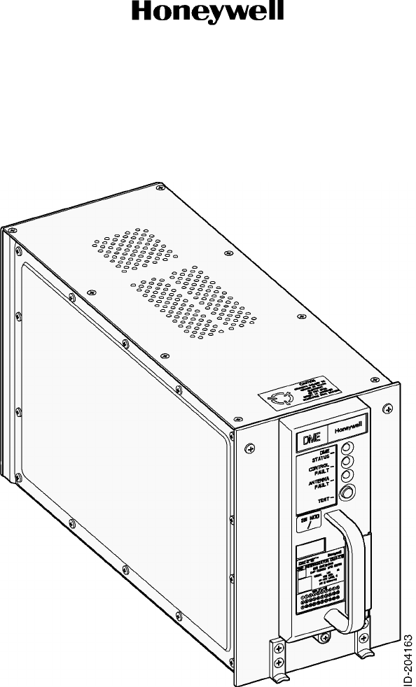
is illustrated in Figure 1 and Figure 2.
Figure 1. DMA-37B DME Interrogator, 066-50013-0101, -0202, and -0303
Page 2
10 Oct 2007
34-51-02
MAINTENANCE MANUAL
DMA-37B DME System
© Honeywell International Inc. Do not copy without express permission of Honeywell.
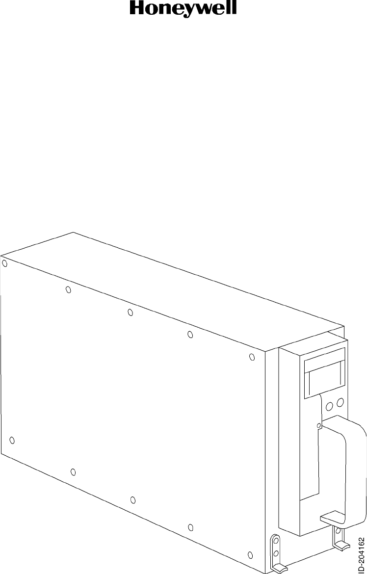
Figure 2. DMA-37B DME Interrogator, 066-50013-1101 and -1212

Page 3
10 Oct 2007
34-51-02
MAINTENANCE MANUAL
DMA-37B DME System
© Honeywell International Inc. Do not copy without express permission of Honeywell.
B. Purpose of Equipment
(1) The DMA-37B DME System is designed to provide the flight crew with accurate
slant-range distance information in digital format as measured from the aircraft to a
selected ground-based DME transponder. Depending upon the DME display, DMA-37B
adds ground speed and time for the aircraft to reach the selected ground-base station at
the current velocity can be derived from the slant-range.
(2) A DME is co-located at ground-based VHF Omnirange Distance Measuring Equipment
(VOR-DME) and VHF Omnirange Tactical Air Navigation (VORTAC) stations. The
DMA-37B is capable of receiving the distance measurement from military Tactical Air
Navigation (TACAN) stations. A few DMEs are co-located with ILS systems presenting
distance and aircraft speed to the runway as the aircraft approaches for landing.
(3) DME is used in conjunction with a primary navigation source, like VOR, to measure
distance along a route of flight toward the VORTAC station. For some instrument
approaches, it is used with VOR to fly where a DME arc or VOR-DME equipment is
required for approach.
(4) The DMA-37B DME Interrogator is a very powerful scanning DME. In addition to stations
selected by the crew, it searches automatically for up to five stations within a
300-nautical mile range.
(5) The operating range of the DMA-37B DME System is zero to 300 nautical miles. The
DMA-37B DME System consists of an airborne DMA-37B DME Interrogator, a mount, a
DME indicator, and an antenna.
(6) The DMA-37B DME Interrogator design conforms to industry standards Aeronautical
Radio Incorporated (ARINC) 709-8 Airborne Distance Measuring Equipment, Radio
Technical Commission for Aeronautics (RTCA) document number DO-189 Minimum
Operational Performance Standards (MOPS) for Airborne Distance Measuring
Equipment (DME), and European Organisation for Civil Aviation Equipment
(EUROCAE) ED-54 Minimum Operational Performance Requirements for Distance
Measuring Equipment Interrogator, and digital guidance data conforms to ARINC
429-14 Mark 33 Digital Information Transfer System (DITS) format.
(7) The DMA-37B DME Interrogator is fully interchangeable with the earlier ARINC 709
DMA-37A DME Interrogator for backward compatibility.
(8) In addition, the DMA-37B provides fast scan and digital Morse Code decoding outputs,
fault memory, and built-in test equipment (BITE) interfaces for use in a Central
Maintenance Computer (CMC) in accordance with ARINC 604 to transfer maintenance
data or in a Central Fault Display System (CFDS) in accordance with ARINC 604, and
Airbus Industrie ABDO048C or McDonnell Douglas software requirements.
C. Equipment Part Numbers
(1) Components of the DMA-37B DME System supplied by Honeywell are listed in Table 1.
Table 1 lists the currently available components of the system, along with part numbers
and equipment type numbers.

Page 4
10 Oct 2007
34-51-02
MAINTENANCE MANUAL
DMA-37B DME System
© Honeywell International Inc. Do not copy without express permission of Honeywell.
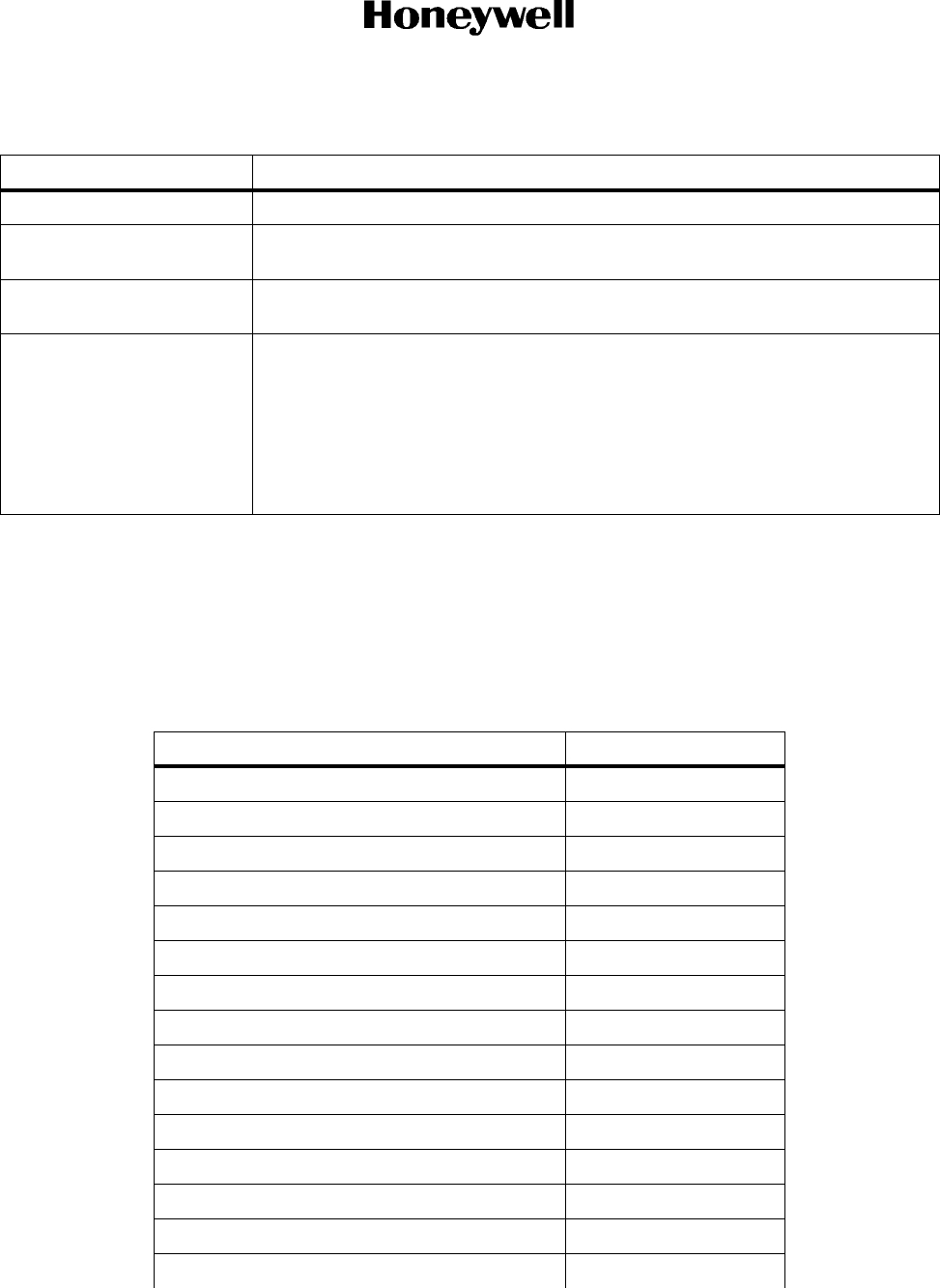
Table 1. DMA-37B DME System Components (Honeywell Supplied)
Equipment
Type Number Equipment Description Part Number
DMA-37B DME
Interrogator
A microprocessor-based distance measuring equipment used to
determine the slant-range distance as measured from the aircraft to
a selected ground-based DME transponder. Derived distance
information is made available for visual display to the pilot, and for
use by an automatic flight control system.
Design conforms to ARINC 809-8 and EUROCAE ED-54; digital
guidance data output ports (binary digital distance, BCD digital
distance, station identification and BCD channel selected) conforms
to ARINC 429 format; two digital input ports for frequency/function
select data input and source select capability operate in accordance
with ARINC 429.
In addition to the automatic self-test feature, the unit contains an
loperator-initiated self-test feature, located on the DMA-37B front
panel, that provides a comprehensive test of all sections of the unit
and operation of its outputs.
Complies with DO-178B software requirements and enhanced BITE
requirements of Airbus, Boeing, and McDonnell Douglas.
Capable of interfacing CMC in accordance with ARINC 604.
Capable of data recording and loading through the front of the unit.
Meets D0-160C lightning protection and 200 ms power interrupt
transparency requirements.
Meets HIRF requirements and ICAO Annex 10 requirements.
Valid station identification is output for the Ident channel only, BCD
distance is output for all foreground channels (only the Display
Channel is valid) and output label 035 has its sign status matrix
(SSM) set to NORMAL in the standby mode.
066-50013-0101
Same as -0101, except valid station identification is output for all
foreground channels simultaneously (multichannel Ident), BCD
distance is output only for the Display Channel (unless no Display
Channel is selected) and output label 035 has its SSM set to
no-computed-data (NCD) in the standby mode.
Capable of interfacing CFDS in accordance with ARINC 604 and
Airbus Industrie ABDO048C.
066-50013-0202
Same as -0202 except capable of interfacing CFDS in accordance
to McDonnell Douglas software requirements (replaces ABDO048C
implementation).
066-50013-0303
Same as the -0101 except upgraded to DO-160E configuration. Unit
also upgraded with variable frequency capability with harmonic
correction for input power. Front panel consists of easy to use LED
fault and status indicators in place of LCD display.
066-50013-1101
Same as the -0202 except upgraded to DO-160E configuration. Unit
also upgraded with variable frequency capability with harmonic
correction for input power. Front panel consists of easy-to-use LED
fault and status indicators in place of LCD display. In addition, the
ARINC 429 capability has been upgraded to have a burst mode
capability.
066-50013-1212

Page 5
10 Oct 2007
34-51-02
MAINTENANCE MANUAL
DMA-37B DME System
© Honeywell International Inc. Do not copy without express permission of Honeywell.
D. Equipment Required but Not Supplied
(1) Table 2 lists equipment required for the RVA-36B VOR/Marker System, but not supplied
by Honeywell.
E. Configurations Available
(1) Table 3 lists the available configurations of the DMA-37B and the features contained in
each configuration. Table 4 contains a brief description of each feature.
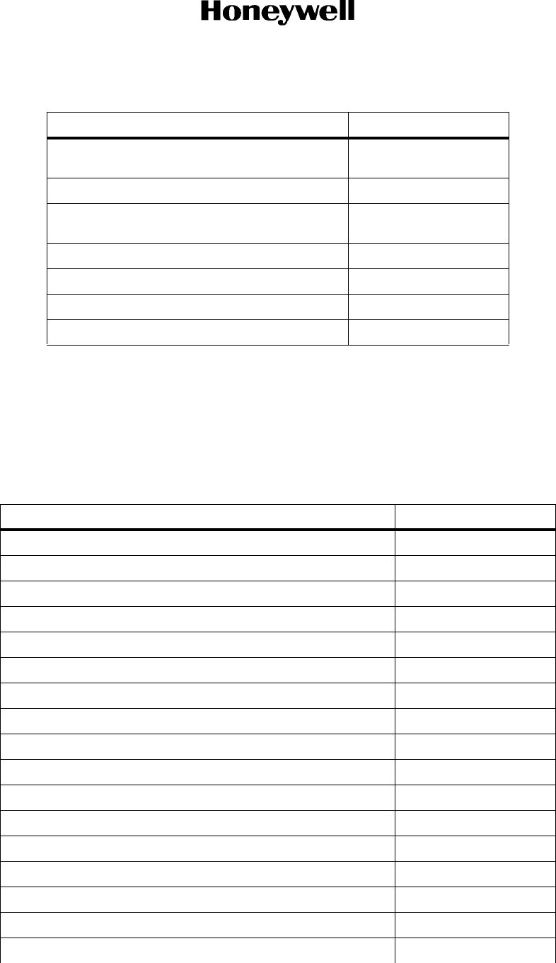
Table 2. Equipment Required but Not Supplied
Equipment Description
Power Source AC power supply of 115 V, 400 Hz as defined by Radio Technical Commission
for Aeronautics, Inc. (RTCA) D0-160C. The -1101 and 1212 are rated for
DO-160E variable frequency operation with harmonic content correction.
NAV Control Panel DME frequency automatically paired with NAV frequency. Must provide remote
control of frequency selection in serial digital ARINC 429 format, power on-off,
and self-test in ARINC 429 format.
Distance Indicator A display which indicates distance to the selected DME ground station.
Communication with DMA-37B is on an ARINC 429 data bus.
Audio Distribution System Audio system with an input impedance of 200 to 10,000 ohms.
DME Antenna L-Band, vertically polarized antenna capable of receiving DME signals over a
frequency range of 962.00 MHz to 1213.00 MHz, and capable of transmitting
DME signals over a frequency range of 1025 MHz to 1150 MHz.
4 MCU Unit Mount Interrogator in the aircraft. Designed in accordance with ARINC 600. Mount
connector will allow mating of DMA-37B low-insertion force, size 2, ARINC 600
connector with three inserts. The middle insert will be used for aircraft
interconnections. The bottom insert will be used for input power. The middle
insert is also used for coaxial antenna connections. Keying pins will be indexed
to pin code 03.
Cooling Source Aircraft supplied ARINC 600 forced-air cooling is required for the DMA-37B.
Cable and Connectors Necessary connectors, power cables, RF cables, and aircraft interwiring are
shown in DMA-37B DME System Interwiring Diagram, Figure 2006.
Table 3. DMA-37B DME Interrogator Available Configurations
HPN
Features
Basic Unit Fault Memory
Interface
Boeing CMC Airbus CFDS
McDonnell
Douglas CFDS
066-50013-0101 X X X
066-50013-0202 X X X
066-50013-0303 X X X
066-50013-1101 X X X
066-50013-1212 X X X

Page 6
10 Oct 2007
34-51-02
MAINTENANCE MANUAL
DMA-37B DME System
© Honeywell International Inc. Do not copy without express permission of Honeywell.
Table 4. DMA-37B DME Interrogator Features
Feature Description
Basic Unit A microprocessor-based distance measuring equipment used to determine the
slant-range distance as measured from the aircraft to a selected ground-based DME
transponder. Derived distance information is made available for visual display to the
pilot, and for use by an automatic flight control system.
Design conforms to ARINC 709-8 and EUROCAE ED-54; digital guidance data output
ports (binary digital distance, BCD digital distance and BCD channel selected)
conforms to ARINC 429 format; two digital input ports for frequency/function select
data input and source select capability operate in accordance with ARINC 429.
In addition to the automatic self-test feature, the unit contains an operator-initiated
self-test feature, located on the DMA-37B front panel, that provides a comprehensive
test of all sections of the unit and operation of its outputs.
The -1101 and -1212 units feature LEDs. The other dash numbers have an LCD
display.
Complies with DO-178B software requirements and enhanced BITE requirements of
Airbus, Boeing, and McDonnell Douglas.
With the exclusion of -1101 and -1212 the remaining dash numbers are capable of data
recording and loading through the front of the unit.
Meets D0-160C lightning protection and 200 ms power interrupt transparency
requirements. The -1101 and -1212 units are also rated for DO-160E operation.
Meets HIRF requirements and ICAO Annex 10 requirements.
Fault Memory A nonvolatile, single-chip fault memory that allows the recording of faults associated
with a particular flight leg. Sixty-four flight legs are available with each flight leg made
up of a flight-leg information header containing a fault record section for recording
ten airborne faults and three ground faults. When all flight legs have been used, the
oldest flight leg is reused.
CMC Interface The DMA-37B interfaces fault memory and BITE data between DME Interrogator and
line maintenance Centralized Maintenance Computer (CMC) for the purpose of
extracting maintenance information and initiating tests. Designed to conform with
ARINC 429 interfaces and ARINC 604.
CFDS Interface The DMA-37B interfaces fault memory and BITE data between DME Interrogator and
line maintenance Centralized Fault Display Interface Unit (CFDIU) for the purpose of
extracting maintenance information and initiating tests. Designed to conform with
ARINC 429 interfaces, ARINC 604 and Airbus Industrie ABDO048C or McDonnell
Douglas software requirements
Digital Morse Code Provides capability of receiving ground-facility digital Morse Code Ident signals and
decoding them to ARINC 429 data word format for use on the DME Interrogator system
ARINC 429 data output bus.
Multichannel Ident Valid station identification is output for all foreground channels simultaneously, BCD
distance is output only for the display channel (unless no display channel is selected),
and output label 035 has its SSM set to NCD in standby mode; otherwise, without
multichannel ident, valid station identification is output for the Ident channel only, BCD
distance is output for all foreground channels (only the display channel is valid), and
output label 035 has its SSM set to NORMAL in standby mode.

Page 7
10 Oct 2007
34-51-02
MAINTENANCE MANUAL
DMA-37B DME System
© Honeywell International Inc. Do not copy without express permission of Honeywell.
2. System Leading Particulars
A. Unit Specifications
(1) Table 5 lists the leading particulars for the DMA-37B DME System.
Table 5. Leading Particulars
Characteristics Description
General
Power Requirements 115 V ac, 380 to 420 Hz, 22 W (-0101, -0202, and -0303 only)
115 V ac, 360 to 800 Hz, 25 W (-1101 and -1212 only)
Weight 9.8 lb (4,45 kg)
Dimensions See Figure 2005.
Form Factor ARINC 600 4 MCU
Cooling ARINC 600 forced air
Temperature
• Operating -67 to +158 °F (-55 to +70 °C) for -0101, -0202, and -0303 only
+5 to +158 °F (-15 to +70 °C) for -1101 and -1212 only
• Storage -85 to +158 °F (-65 to +85 °C)
Humidity Zero to 95% Relative Humidity
Warm-up period Stable operation within one minute after application of power
Frequency Selection Serial digital in accordance with ARINC 429
Range Zero to 300 Nautical Miles
Altitude 50,000 feet above mean sea level
Velocity Zero to 1000 Knots
Self Test Continuous, automatic; Manual from discrete ARINC 429, CMC, or Front Panel
Integrity Monitoring Continuous self-monitoring
Fault Reporting ARINC 429 and ABD 0048B Centralized Maintenance Interfaces
Data Outputs ARINC 429 Distance and CMC Interface
Certification
• -0101, -0202, and -0303 TSO C66c
DO-160C Environmental Category
/A2D2/ZCA/MNB/XXXXXXAEAEZUZ/XXE2/XX
ICAO Annex 10 FM Immunity
DO-189, DO-178B
•-1101 TSO C66c
DO-160E Environmental Category
[(A2)(B2)V]BAB[SB]XXXXXXAA(WF)XA[R(WF)][ZW]RRRL[ZZZZ]XXAC
ICAO Annex 10 FM Immunity
DO-189, DO-178B

Page 8
10 Oct 2007
34-51-02
MAINTENANCE MANUAL
DMA-37B DME System
© Honeywell International Inc. Do not copy without express permission of Honeywell.
• -1212 TSO C66c
DO-160E Environmental Category
[(A2)(D2)Z]BAB[SB]XXXXXXAA(WF)HA[R(WF)][ZW]R[RR]L[ZZZZ]XXAC
ICAO Annex 10 FM Immunity
DO-189, DO-178B
Transmitter
Frequency Range 1025.00 MHz to 1150.00 MHz, 1MHz channel spacing
Frequency Stability ± 80 kHz
Power Output 700 Watts, Typical
Pulse Code Spacing
• X-Channel 12.0 ± 0.4 microseconds
• Y-Channel 36.0 ± 0.4 microseconds
Frequency Spectrum 90% of total pulse energy within ± 0.25 MHz of channel frequency
Rise Time (maximum) 2.8 Microseconds (consistent with pulse spectrum)
CW Leakage at Antenna
Connector
-79 dBm maximum
Antenna Mismatch No damage to transmitter with antenna open or short circuit
Receiver
Frequency 962.00 MHz to 1213 MHz (252 Channels)
Sensitivity -90 dBm minimum lock-on level
Selectivity
Dynamic Range 80 dB minimum
Image Rejection 60 dB minimum
CW Rejection 60 dB minimum
Audio Output Capable of 40 milliwatts minimum into a 200-ohm to 10,000 ohm resistive load
with -87 dBm input signal level.
Harmonic Distortion Less than 15% with 1000 microvolts modulated 30% at 1000 Hz and less than
20% with 90% modulation for rated audio output into a 200-ohm to 600-ohm
resistive load
Audio Output Regulation Less than 6-dB voltage change from a 25-milliwatt reference level into 200
ohms for resistive load variations of 200 ohms to 10,000 ohms
Less than 0.31-dB voltage change from a 40-milliwatt level into 600-ohm
reference for resistive load variations of 453 ohms to 2400 ohms.
Table 5. Leading Particulars (cont)
Characteristics Description
Attenuation Bandwidth
Less than 6 dB 95 kHz
More than 50 dB ±800 kHz
Page 9
10 Oct 2007
34-51-02
MAINTENANCE MANUAL
DMA-37B DME System
© Honeywell International Inc. Do not copy without express permission of Honeywell.
B. Environmental Certification (066-50013-0101, -0202, and -0303 only)
(1) The DMA-37B DME Interrogator meets the environmental conditions of the Radio
Technical Commission for Aeronautics (RTCA) document number D0-160C,
Environmental Conditions and Test Procedures for Airline Electronic/Electrical
Equipment and Instruments (refer to Table 6). The environmental certification categories
of the DMA-37B are /A2D2/ZCA/MNB/XXXXXXAEAEZUZ/XXE2/XX (refer to Table 6).
Audio Noise Level Greater than 30 dB below audio reference level.
Digital Range Output Distance available in fractional binary format and BCD format in accordance
with ARINC 709 and ARINC 429 standards.
Warning Signals Digital warning signals provided in accordance with ARINC 709 and ARINC
429 standards
Distance Accuracy
Table 6. Environmental Certification (066-50013-0101, -0202, and -0303 only)
Test Category
Temperature and Altitude A2D2
In-Flight Loss of Cooling Z
Temperature Variation C
Humidity A
Operational Shocks and Crash Safety Operational Shock
Vibration MNB
Explosion Proofness X
Waterproofness X
Fluids Susceptibility X
Sand and Dust X
Fungus Resistance X
Salt Spray X
Magnetic Effect A
Power Input E
Voltage Spike A
Table 5. Leading Particulars (cont)
Characteristics Description
Signal Level Accuracy
Lock-on to -80 dBm 0.2 NM
Lock-on from -80 to -10 dB 0.1 NM
Page 10
10 Oct 2007
34-51-02
MAINTENANCE MANUAL
DMA-37B DME System
© Honeywell International Inc. Do not copy without express permission of Honeywell.
C. Environmental Certification (066-50013-1101 only)
(1) The DMA-37B DME Interrogator meets environmental conditions of RTCA document
number DO-160E In addition to several Boeing Specific requirements (refer to Table 7).
The environmental certification categories for the -1101 DMA-37B DME Interrogator are
[(A2)(B2)V]BAB[SB]XXXXXXAA(WF)XA[R(WF)][ZW]RRRL[ZZZZ]XXAC (refer to
Table 7).
Audio Frequency Conducted Susceptibility -
Power Inputs
E
Induced Signal Susceptibility Z
Radio Frequency Susceptibility
(Radiated and Conducted)
U
Emission of Radio Frequency Energy Z
Lightning-Induced Transient Susceptibility XXE2
Lightning-Direct Effects X
Icing X
Table 7. Environmental Certification (066-50013-1101 only)
Test Category
Ground Survival Low Temperature A2
Short Term Operating Low Temperature A2
Operating Low Temperature A2
Ground Survival High Temperature A2
Short Term Operating High Temperature A2
Operating High Temperature A2
In-Flight Loss of Cooling V
Altitude B2
Decompression A2
Overpressure A2
Temperature Variation B
Humidity A
Acceleration X
Vibration Due to Fan Blade Loss (Windmilling) X
Bench Handling Shock X
Shipping Container X
Operational Shock (Emergency Landing and Bird Strike) B
Table 6. Environmental Certification (066-50013-0101, -0202, and -0303 only) (cont)
Test Category

Page 11
10 Oct 2007
34-51-02
MAINTENANCE MANUAL
DMA-37B DME System
© Honeywell International Inc. Do not copy without express permission of Honeywell.
Vibration S
Explosive Atmosphere N/A
Waterproofness N/A
Fluids Susceptibility N/A
Sand and Dust N/A
Fungus Resistance N/A
Salt Fog N/A
Magnetic Effect A
Power Input A(WF)
Voltage Spikes A
Voltage Waveform - Individual Harmonic Content (AF
Conducted Susceptibility)
R(WF)
AF Magnetic Field Susceptibility – Equipment ZW
AF Magnetic Field Susceptibility – Wiring ZW
AF Electric Field Susceptibility – Wiring ZW
Spikes Induced into Interconnecting Cables ZW
Radio Frequency Conducted Susceptibility R
Radio Frequency Radiated Susceptibility R
Certification HIRF Environment I by Direct Injection Method X
AF Conducted Emissions, AF Capacitive Coupling X
AF Conducted Emissions, AF Inductive Coupling X
RF Conducted Emissions (Narrowband) M
RF Conducted Emissions (Broadband) X
RF Radiated Emissions (Narrowband) M
RF Radiated Emissions (Broadband) X
Lightning-Induced Transient Susceptibility, Pin Injected ZZZZZ
Lightning-Induced Transient Susceptibility, Cable Injected ZZZZZ
Lightning-Induced Transient Susceptibility, Ground Injected ZZZZZ
Lightning-Induced Transient Susceptibility, Multiple Burst X
Lightning Direct Effects N/A
Icing N/A
Electrostatic Discharge (ESD) A
Fire, Flammability C
Table 7. Environmental Certification (066-50013-1101 only) (cont)
Test Category

Page 12
10 Oct 2007
34-51-02
MAINTENANCE MANUAL
DMA-37B DME System
© Honeywell International Inc. Do not copy without express permission of Honeywell.
D. Environmental Certification (066-50013-1212 only)
(1) The DMA-37B DME Interrogator meets environmental conditions of RTCA document
number DO-160E In addition to several Boeing Specific requirements (refer to Table 8).
The environmental certification categories for the -1212 DMA-37B DME Interrogator are
[(A2)(D2)Z]BAB[SB]XXXXXXAA(WF)HA[R(WF)][ZW]R[RR]L[ZZZZ]XXAC (refer to
Table 8).
Table 8. Environmental Certification (066-50013-1212 only)
Test Category
Temperature Test A2
In-Flight Loss of Cooling Z
Temperature Variation B
Altitude Test D2
Decompression Test A2
Overpressure Test A2
Humidity A
Operational Shock And Crash Safety B
Vibration S
Vibration Due to Fan Blade Loss (Windmilling) X
Vibration: Due to Landing Gear Tyre Burst X
Explosive Atmosphere X
Waterproofness X
Fluids Susceptibility X
Sand and Dust X
Fungus Resistance X
Salt Fog X
Magnetic Effect A
Power Input A (WF)
Voltage Spike A
Audio Frequency Conducted Susceptibility R(WF)
AF Electric Field Susceptibility – Wiring ZW
AF Magnetic Field Susceptibility – Wiring ZW
AF Magnetic Field Susceptibility – Equipment ZW
Spikes Induced into Interconnecting Cables ZW
Radio Frequency Conducted Susceptibility R
Radio Frequency Radiated Susceptibility R

Page 13
10 Oct 2007
34-51-02
MAINTENANCE MANUAL
DMA-37B DME System
© Honeywell International Inc. Do not copy without express permission of Honeywell.
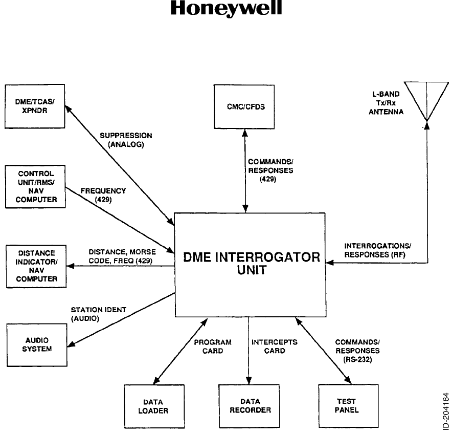
3. System Description
A. General
(1) The DMA-37B DME System is an airborne distance measuring system which
determines the slant-range distance from an aircraft to a selected ground based DME
transponder (see Figure 3). The DMA-37B DME Interrogator transmits a pulse-pair
signal on any one of 126 frequencies within the range of 1025 MHz to 1150 MHz. One
hundred of the DMA-37B transmit frequencies are automatically selected by tuning the
NAV control to a frequency between 108.00 and 117.95 MHz. The other 26 frequencies
can be selected by tuning the NAV control to frequencies between 133.30 and 135.95
MHz, these channels are normally used for military TACAN stations. The data loader and
data recorder capability in Figure 3 are used in the -0101, -0202, -0303 only
(2) The signals transmitted by the airborne DMA-37B are received by the ground station
assigned to the selected channel frequency. After a built-in delay of 50 microseconds, a
reply pulse-pair is automatically transmitted on the channel frequency assigned to the
ground station. There are 252 channels within the frequency band of 962 to 1213 MHz
set aside for DME ground stations.
(3) The DMA-37B receives the response to the interrogations and processes these signals
to determine the precise amount of time that has elapsed between transmission of a
pulse pair and reception of the response. The DMA-37B computes the slant-range
distance by subtracting the 50 microsecond delay and dividing the result by 12.359
microseconds (time required for DME signal to travel to and return from a DME ground
station that is one mile away). The distance is computed every time a pulse pair
response is received from the ground station.
(4) An operator initiated self-test feature is also included in theDMA-37B. The self-test is
initiated by pressing the TEST pushbutton on the front panel of the DMA-37B. There are
one or more additional means of initiating the self test; these switches can be located on
the DME tuning source, DME indicator, or an EFIS (electronic flight instrument system)
indicator.
RF Conducted Emissions
(Narrowband)
L
RF Radiated Emissions (Narrowband) L
Lightning-Induced Transient Susceptibility, Pin Injected ZZZZZ
Lightning-Induced Transient Susceptibility, Multiple Pulse (Burst) ZZZZZ
Lightning-Induced Transient Susceptibility, Multiple Stroke ZZZZZ
Lightning Direct Effects X
Icing X
ESD Susceptibility A
Fire, Flammability C
Table 8. Environmental Certification (066-50013-1212 only) (cont)
Test Category
Page 14
10 Oct 2007
34-51-02
MAINTENANCE MANUAL
DMA-37B DME System
© Honeywell International Inc. Do not copy without express permission of Honeywell.
Figure 3. DMA-37B DMA System
(5) An automatic self-test feature is also built into the DMA-37B. This test is controlled by
the microprocessor program. Approximately once every 1.5 seconds the program
automatically instructs the unit to go into self test. The results of the test are monitored
and compared against information stored in memory. If any results of the test indicate a
malfunction, a DME invalid flag is generated and routed to DME distance users through
the ARINC 429 output.
(6) The DME ground station transmits a station-identification signal along with the other
data. The DMA-37B detects the station-identification signal and applies it to the aircraft
audio system.
(7) The DMA-37B generates a suppression pulse for internal use and also makes the pulse
available at the rear connector of the unit. The pulse can be used to suppress other
receivers when DME interrogation pulses are being transmitted. The DMA-37B can also
receive suppression pulses from external equipment on the mutual suppression line.

Page 15
10 Oct 2007
34-51-02
MAINTENANCE MANUAL
DMA-37B DME System
© Honeywell International Inc. Do not copy without express permission of Honeywell.
4. System Component Description
A. DMA-37B DME Interrogator
(1) The DMA-37B DME Interrogator is packaged in an ARINC 600 Characteristic, 4 MCU
standard form factor case. It contains the electronics required to transmit and receive the
pulse modulated L-band signal required by the ground station transponder and to
interface with the aircraft systems.
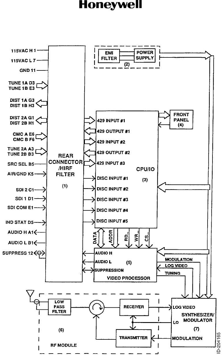
(2) The basic -0101, -0202, and -0303 DMA-37B consists of a RF module, a
synthesizer/modulator module, a video processor module, CPU-I/O module, power
supply assembly, HIRF/rear interconnect assembly, front panel assembly, and memory
card interface module (see Figure 4).
(3) The basic -1101 and -1212 DMA-37B consists of a RF assembly, an integrated video
main processor assembly, a variable frequency power factor corrected power supply
assembly, a rear interconnect assembly containing lightning protection, and a front panel
assembly (see Figure 4).
(4) The DMA-37B uses a low insertion force, size two shell, ARINC 600 rear panel
connector with three inserts. The top insert is not used. The middle insert is used for
aircraft interconnections and coaxial antenna connector, and the bottom insert is used
for input power and suppression coaxial connectors. The keying pins are set to index pin
code 03.
(5) Forced air cooling, in accordance with ARINC specification 600, is required for cooling
the DMA-37B.
(6) Data interfaces to the aircraft systems are through slow-speed ARINC 429 ports.
(7) A variety of discrete and strap pins provide additional information to and from the DME.
(8) The -0101, -0202, and -0303 front panel display provides an interface to an operator with
a liquid crystal display (LCD) that is visible from the front of the DMA-37B to display
messages in simple language in one of four modes: normal operation, BITE display,
maintenance, and software loading.
(9) Software loading and data recording to/from the CPU is through the front panel Personal
Computer Memory Card International Association (PCMCIA) slot. Intel Series 2 Flash
Cards with capabilities ranging from 1, 2, or 4 megabytes are supported.
(10) Intel Series 2 Flash Cards with capabilities ranging from 4, 10, and 20 megabytes (up to
64 megabytes, when available) are also supported.
(11) Two pushbutton switches allow operator interface with the DMA-37B LCD.
(12) In normal operation, the front panel LCD displays the unit's characteristics: unit
identification, part number, and serial number (-0101, -0202, and -0303 only). The BITE
display mode is activated after manual self-test has been exercised either from the front
panel test pushbutton or remotely. In the BITE mode, BITE status is reported and, in the
event of a detected failure, additional help screens are provided to locate the detected
failure to a module. BITE help pages are provided. In the maintenance mode, a set of
maintenance words are displayed and decoded showing the names of data fields and
the value of the data. Maintenance help pages are provided. For loading software, a
series of screens direct the operator during the data loading process. Software version
and loading status are provided during the update process.
(13) The -1101 and -1212 front panel assembly consists of three easy to see LED indicators
that display the status of the unit.
B. Other Components in the System
(1) Other DMA-37B DME System components are not supplied by Honeywell. Information
on these units must be obtained from their respective manufacturers.
Page 16
10 Oct 2007
34-51-02
MAINTENANCE MANUAL
DMA-37B DME System
© Honeywell International Inc. Do not copy without express permission of Honeywell.
NOTE: In the -1101 and -1212 units, the synthesizer modulator is included in the RF module. In addition,
the video processor module is included in the CPU/IO module.
Figure 4. DMA-37B DME Interrogator Simplified Block Diagram

Page 17
10 Oct 2007
34-51-02
MAINTENANCE MANUAL
DMA-37B DME System
© Honeywell International Inc. Do not copy without express permission of Honeywell.
5. Operation
A. General
(1) The DMA-37B DME Interrogator transmits a pair of pulses through the antenna on one
frequency and waits for a ground station reply on a frequency offset by 63 MHz. The
ground station replies to this interrogation 50 microseconds later, somewhat like a
delayed radar reflection.
(2) The 50-microsecond delay allows completion of the interrogation. If not delayed at close
ranges, the returned signal would come back to the receiver before the transmitted
pulses have left the aircraft antenna. When a DME unit measures 50 microseconds from
transmit time until the beginning of the received pulse, the aircraft is at 0.0 mile range.
(3) Like radar, the unit calculates the distance from the station based on speed of the
transmitted pulses through the air, divided by time. Speed of signal propagation equals
one nautical mile per 12.369 microseconds.
(4) Each DME unit must distinguish its own pulse return from other DME returns or squitters
(unsolicited replies emitted by the ground station). To do this, reply/squitter distances
from multiple interrogations are saved and compared to determine actual reply distance
to the ground station. The DME is capable of simultaneously maintaining track of up to
five different ground stations that are tuned by a Flight Management System.
B. Basic Theory
(1) RF Module
(a) This module consists of a single PC board that is mounted in a closed aluminum
chassis. It contains the transmitter, receiver, circulator and a low-pass filter.
(b) The solid-state transmitter contains a six-stage amplifier followed by a 700 W
(typical) final amplifier. The pulse modulation is applied to the first six stages of
amplification. It is tuned to frequencies in the range 1025 to 1150 MHz.
(c) The single-conversion superheterodyne receiver consists of a varactor tuned
preselector, 1-GHz preamplifier, mixer, SAW band-pass filters, and a 63-MHz
logarithmic IF amplifier. The preselector is tuned to frequencies in the 962 to 1213
MHz range.
(d) The circulator routes the transmitter output to the antenna and the antenna received
signal to the receiver. It provides isolation to protect the transmitter output amplifier
devices from reflected signals due to high VSWR conditions.
(e) The low-pass filter prevents internal transmitter harmonics from being passed to the
antenna.
(2) Synthesizer/Modulator Assembly
NOTE: On the -1101 and -1212 units, the synthesizer/modulator assembly has
been combined into the RF assembly.
(a) This module contains the digital frequency synthesizer and transmitter modulator
circuits.
(b) The digital frequency synthesizer supplies an RF signal used both as the local
oscillator input to the receiver mixer and as the low-level CW signal into the
transmitter. This circuit consists of a phase-locked loop and VCO which is tuned to
the desired channel frequency by a serial tuning word supplied by the video
processor module.

Page 18
10 Oct 2007
34-51-02
MAINTENANCE MANUAL
DMA-37B DME System
© Honeywell International Inc. Do not copy without express permission of Honeywell.
(c) The modulator supplies the on/off signal that corresponds to the X or Y pulse pairs
associated with the channel frequency. An interrogation is transmitted by triggering
the series of on/off modulation to control the transmitter amplifier stages that drive
the final amplifier.
(3) Main Processor (CPU and I/O) Assembly
NOTE: On the -1101 and -1212, units the the main processor function and video
processor function have been combined on one module.
(a) This module contains the CPU that executes the signal processing using an
80486SX microprocessor.
(b) It also contains the I/O section consisting of ARINC 429 transmitters and receivers,
and discrete I/O logic to provide the interfaces with other aircraft systems, including
the Central Maintenance Computer (CMC) and displays.
(c) ARINC 429 inputs and outputs are processed by a specially designed ARINC 429
LSI transceiver device. External level converters are used to satisfy the ARINC 429
characteristics for the transmitters and convert input ARINC 429 signals to logic
levels.
(d) All discrete inputs and outputs external to the DME are processed by discrete
components to provide level shifting and latching.
(e) The following types of devices are employed:
• Digital-to-analog converter devices to generate control and test signals
• Field Programmable Logic Array (FPLA) devices to accept, decode and
generate discrete signals
• Memory devices (bootstrap, program, nonvolatile, and data)
• Data recorder interface
• Front panel display driver
• RS-232 interface
• Clock generators.

Page 19
10 Oct 2007
34-51-02
MAINTENANCE MANUAL
DMA-37B DME System
© Honeywell International Inc. Do not copy without express permission of Honeywell.
(4) Video Processor
(a) This module contains a field programmable gate array (FPGA) which is the control
center for the video processor. The video processor provides the following
operations:
• Converts tuning commands from CPU to serial data to tune the transmit/receive
frequency synthesizer
• Generates the corresponding receiver preselector tuning voltage
• Generates the corresponding X or Y pulse modulation for the interrogation
• Generates the output mutual suppression pulse for an interrogation
• Detects the input mutual suppression pulse and inhibits reception and video
processing
• Determines the log IF noise threshold setting
• Starts the range (distance) counter when an interrogation is transmitted
• Digitizes the video signals from the receiver log IF amplifier
• Validates the amplitude, spacing, and width of the digitized video pulse pairs
• Stores the range counter value in a FIFO when each valid pulse pair is decoded
• Analog-to-digital converter devices to process the received signals and BITE
test point voltages
• Generates the audio tone for the Morse code station identity aural output
• Provides for integrity testing.
(5) Power Supply Assembly
(a) This module is a self-contained, high-efficiency power supply that converts the
115 V ac, 400 Hz AC power into the required DC operating voltages. It includes an
EMI filter to reduce electromagnetic interference from being radiated from the power
lines.
(b) The power supply for the -1101 and -1212 units can operate in accordance with the
DO-160E VF 360 Hz to 800 Hz mode and has harmonic content (power factor)
correction.
(6) HIRF/Rear Interconnect
(a) The rear connector assembly provides the interwiring from the aircraft interface to
the internal modules. A combination of series resistors, transorb devices, and ferrite
pin filters provide HIRF and lightning protection.
(b) For the -0101, -0202, and -0303 units only, to prevent High Intensity Radiation
Fields (HIRF) or lightning from affecting operation by entering through rear
connector cables, an HIRF compartment is formed in the rear of the DMA-37B. The
signal and power cables are filtered by using discrete and distributed filter elements
and limiting devices on the rear interconnect module located inside this HIRF
compartment. The filtered lines are then fed to the appropriate points in the
DMA-37B. The DMA-37B is packaged in an aluminum casting. This seamless main
frame ensures HIRF cannot enter the unit through structural seams. The slots
formed by the removable side covers are sealed against HIRF with protective
gaskets and metal covers.

Page 20
10 Oct 2007
34-51-02
MAINTENANCE MANUAL
DMA-37B DME System
© Honeywell International Inc. Do not copy without express permission of Honeywell.
(7) Front Panel Display Module, -0101, -0202, and -0303 Only
(a) The front panel display module is mounted behind the front panel and provides an
interface to an operator through a low-power liquid crystal display (LCD) that is
visible from the front of the DMA-37B. In addition to the LCD, the module contains
Light Pipe back lighting, temperature compensation circuitry, and a PC board
containing an associated LCD driver, two pushbutton switches used to enter
functional test and to control the display menus, and a D-sub, nine-pin, RS-232
serial type connector.
(b) The RS-232 front panel connector is used for testing the DMA-37B through a
compatible test set or test panel.
(c) The LCD is a bit-mapped display capable of displaying alphanumeric and graphical
symbols. Simple messages written in plain language minimize the potential for
misunderstanding or incorrect interpretation. The LCD displays the following:
• Part Number/Software Identification
•Status
• Results of Level i BITE Tests
• Maintenance Help Pages
• Shop Maintenance Data
• Flight Fault Memory Contents
• Software Loading Status
• Capable of Customizing for Airline Unique Maintenance Messages.
(d) The memory card interface module is used to load software program data into the
CPU or record data from the CPU. The memory card interface module supports
Series 2 FLASH cards through the front panel Personal Computer Memory Card
International Association (PCMCIA) slot. Intel Series 2 cards with capabilities
ranging from 4, 10, and 20 megabytes (up to 64 megabytes, when available) are all
supported. The FLASH card is inserted through the front panel. In one mode, data
stored on the flash card memory module is used to update program or data memory
in the DME Interrogator. In another mode, the flash card memory module functions
as a data recorder for the software program stored in the CPU.
(8) Front Panel Display Module, -1101 and -1212 Only
(a) The front panel display module for the -1101 and -1212 units contain LEDs to
indicate unit operational status and a push button to initiate self test. In addition
there is a 25 pin D connector for a sperate tester interface.
(9) Memory Card Interface Module, -0101, -0202, and -0303 Only
(a) The memory card interface module is used to load software program data into the
CPU or record data from the CPU. The memory card interface module supports
Series 2 FLASH cards through the front panel Personal Computer Memory Card
International Association (PCMCIA) slot. Intel Series 2 cards with capabilities
ranging from 4, 10, and 20 megabytes (up to 64 megabytes, when available) are all
supported. The FLASH card is inserted through the front panel. In one mode, data
stored on the flash card memory module is used to update program or data memory
in the DME Interrogator. In another mode, the flash card memory module functions
as a data recorder for the software program stored in the CPU.
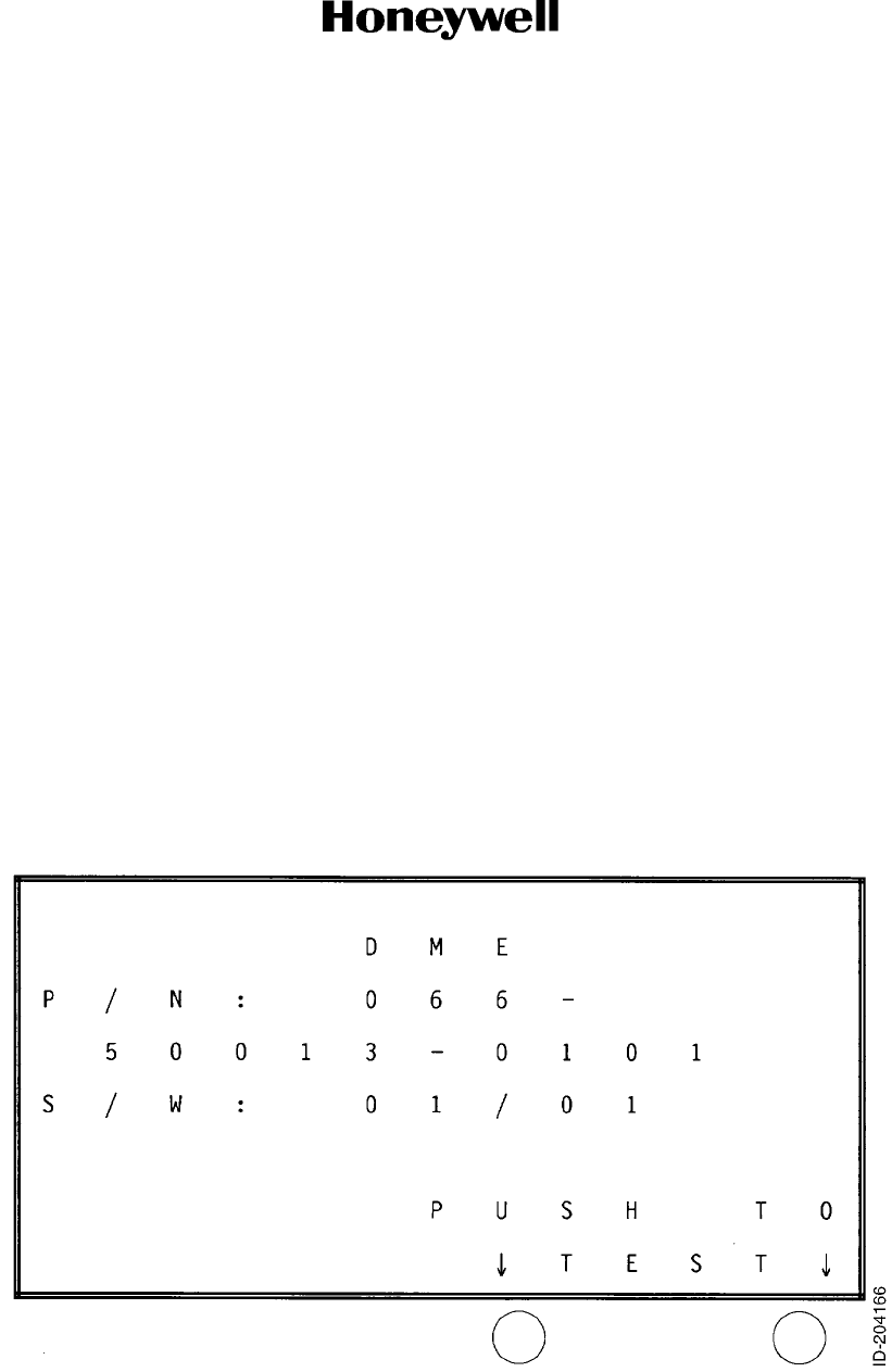
Page 1001
10 Oct 2007
34-51-02
MAINTENANCE MANUAL
DMA-37B DME System
© Honeywell International Inc. Do not copy without express permission of Honeywell.
FAULT ISOLATION
1. General
A. Description for -0101, -0202, and -0303 Only
(1) Fault isolation is the process of isolating the source of a system failure to an LRU (line
replaceable unit) or to the aircraft wiring.
(2) For the -1101 and -1212 units, the front panel display indicates the status of the unit. The
top LED shows the internal status and shows RED with an internal fault. The center LED
is normally off and when displaying RED indicates an external failure with either the
ARINC 429 inputs or unit strapping. The bottom LED shows RED if there is a problem
with the antenna connection. A separate connector on the units can be used with an
adapter to show the indications and functionality described below with the LCD
functions. The LEDs show amber during the self test function described in the following
procedure.
(3) Fault isolation in the DMA-37B DME System includes a continuity check of the
interwiring, and the assurance that proper installation techniques and procedures have
been followed.
(4) A functional self test of the LRU can be initiated by pressing the test key pushbutton
switch as designated on the front panel LCD, see Figure 1001. Although the
normal-mode screen indicates that this actuated from the right key, the left key has the
same function if pressed while the DMA-37B is in its normal mode.
(5) A complete functional test of the system can be performed as described in the
MAINTENANCE PRACTICES section of this manual.
(6) Figure 1002 illustrates the control flow of the LCD screens (except for the data loading
and data recording screens).
Figure 1001. Typical Normal Mode Screen
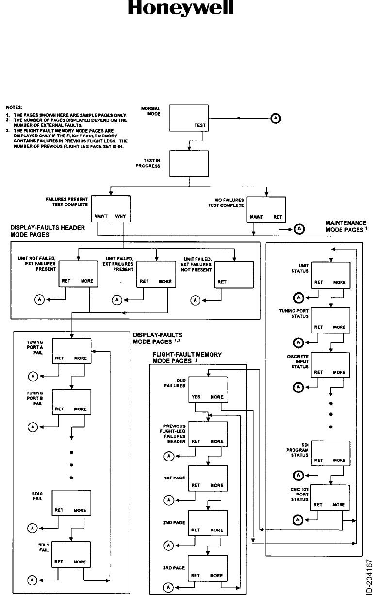
Page 1002
10 Oct 2007
34-51-02
MAINTENANCE MANUAL
DMA-37B DME System
© Honeywell International Inc. Do not copy without express permission of Honeywell.
Figure 1002. LCD Control Flow
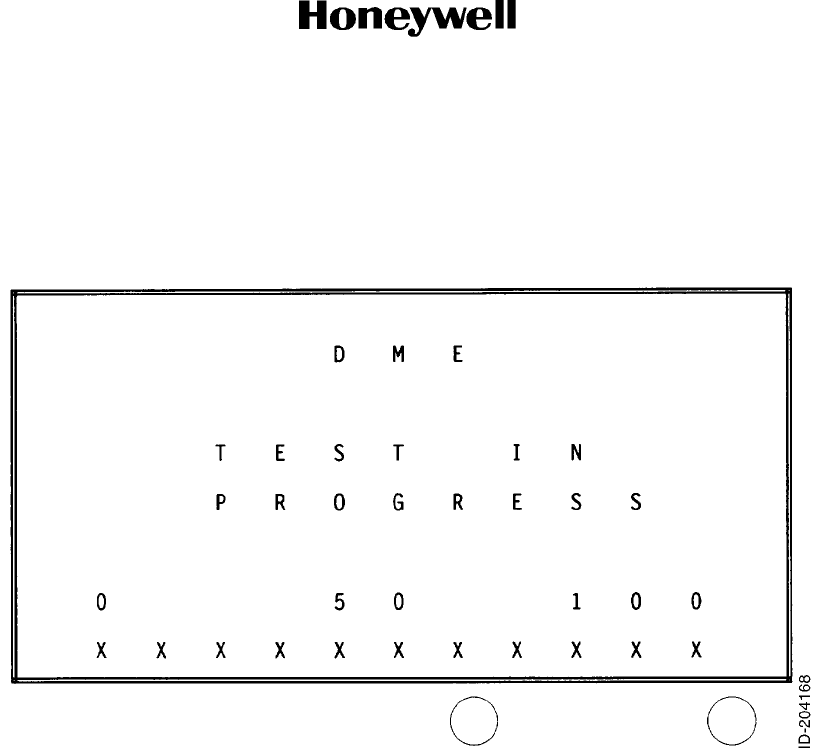
Page 1003
10 Oct 2007
34-51-02
MAINTENANCE MANUAL
DMA-37B DME System
© Honeywell International Inc. Do not copy without express permission of Honeywell.
B. Selt-Test Mode for -0101, -0202, and -0303 Only
(1) The self-test mode starts by displaying the Test in Progress screen, see Figure 1003,
one second after pressing the test key. This is displayed for four seconds with a moving
thermometer along the bottom of the LCD indicating the progress of the test from one to
five seconds.
Figure 1003. Test in Progress Screen
(2) The Normal Mode screen (Figure 1001) is displayed for the first second of the test
sequence.
(3) Once complete, the Test Complete, No Failures screen is displayed (Figure 1004), or
the Test Complete, Failures screen is displayed (Figure 1005). Both screens contain two
key selections each: MAINT and RETURN or MAINT and WHY?, respectively.
• MAINT For both screens, MAINT is located on the left key. This allows the
initiation of the extended maintenance pages of the system for
troubleshooting. Refer to Paragraph D.
• RETURN In the Test Complete, No Failures screen, the RETURN key to the right
returns the system to its normal mode screen (Figure 1001).
• WHY? In the Test Complete, Failures screen, the WHY? key to the right puts
the system into the display-failures mode where individual system
failures are displayed one on each page. Refer to Paragraph C.
(4) While in the self-test mode, not pressing either key for five minutes causes the system
to return to the Normal Mode screen (Figure 1001).
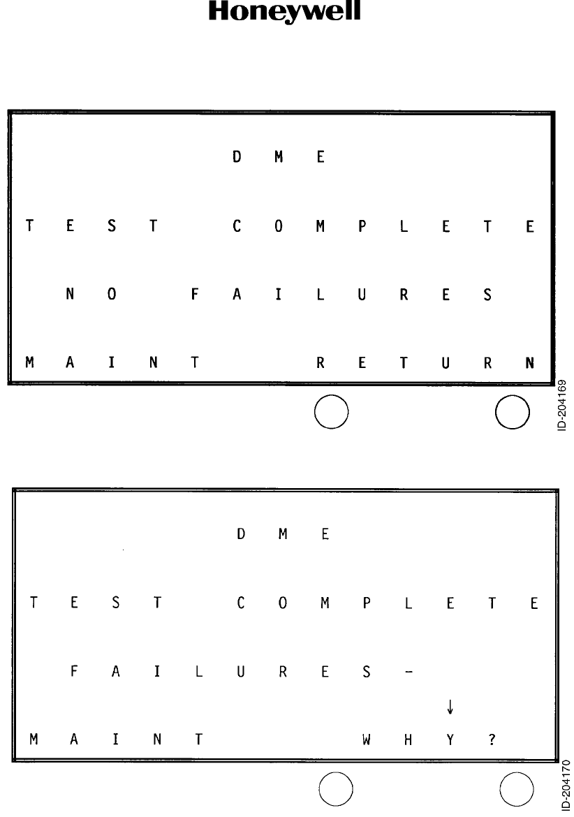
Page 1004
10 Oct 2007
34-51-02
MAINTENANCE MANUAL
DMA-37B DME System
© Honeywell International Inc. Do not copy without express permission of Honeywell.
Figure 1004. Test Complete, No Failures Screen
Figure 1005. Test Complete, Failures Screen
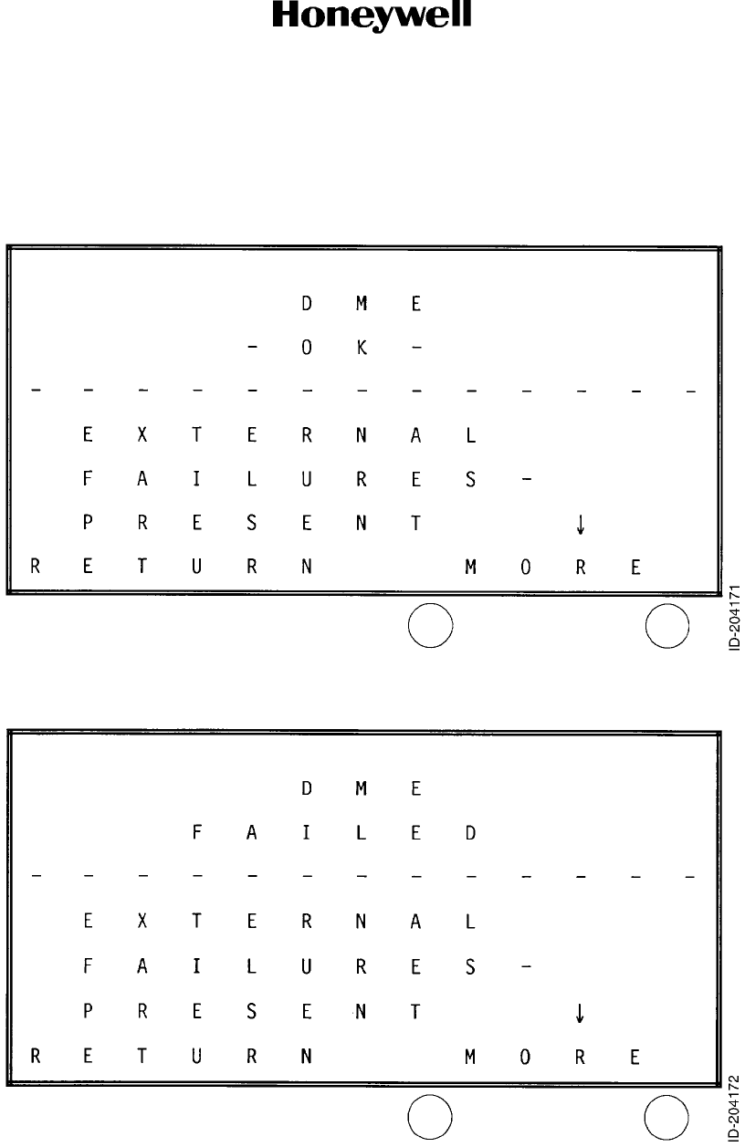
Page 1005
10 Oct 2007
34-51-02
MAINTENANCE MANUAL
DMA-37B DME System
© Honeywell International Inc. Do not copy without express permission of Honeywell.
C. Display-Failures Mode for -0101, -0202, and -0303 Only
(1) One of three failure possibilities exist: the DMA-37B is okay, but there are external
failures (Figure 1006), the DMA-37B failed and there are external failures (Figure 1007),
and the DMA-37B failed, but there are no external failures (Figure 1008).
Figure 1006. DME Receiver OK, External Failures Present Screen
Figure 1007. DME Receiver Failed, External Failures Also Present Screen
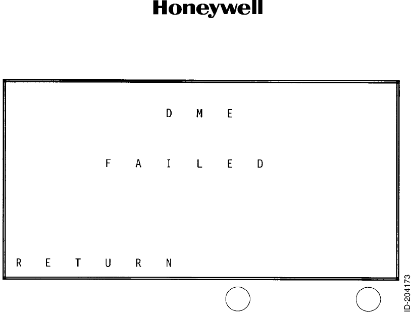
Page 1006
10 Oct 2007
34-51-02
MAINTENANCE MANUAL
DMA-37B DME System
© Honeywell International Inc. Do not copy without express permission of Honeywell.
Figure 1008. DME Receiver Failed, External Failures Not Present Screen
(2) All Display-Failures Mode screens have the MORE selection on the right key. The only
exception is when there is only one failure page. This only happens when the DMA-37B
itself has failed and no other external failure exists Figure 1008).
• MORE Pressing this key cycles through all of the failures present. When on the
last page, the MORE key causes a return to the first displayed failure
page (Figure 1006 or Figure 1007).
(3) All Display-Failures Mode screens have the RETURN selection on the left key.
• RETURN Pressing this key causes the system to return to the Normal Mode
screen (Figure 1001).
(4) While in the display-failures mode, not pressing either key for five minutes causes the
system to return to the Normal Mode screen (Figure 1001).
(5) Figure 1009 thru Figure 1014 show typical display-failure modes that can be
encountered.
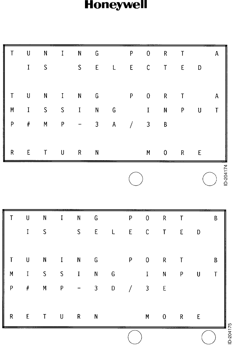
Page 1007
10 Oct 2007
34-51-02
MAINTENANCE MANUAL
DMA-37B DME System
© Honeywell International Inc. Do not copy without express permission of Honeywell.
Figure 1009. Tuning Port A Failure Screen
Figure 1010. Tuning Port B Failure Screen
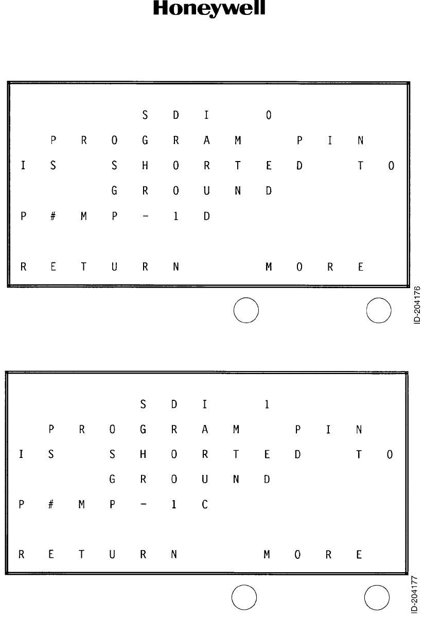
Page 1008
10 Oct 2007
34-51-02
MAINTENANCE MANUAL
DMA-37B DME System
© Honeywell International Inc. Do not copy without express permission of Honeywell.
Figure 1011. SDI 0 Program Pin Failure Screen
Figure 1012. SDI 1 Program Pin Failure Screen
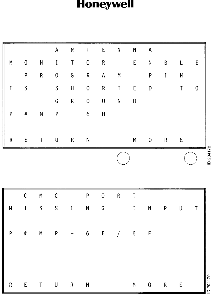
Page 1009
10 Oct 2007
34-51-02
MAINTENANCE MANUAL
DMA-37B DME System
© Honeywell International Inc. Do not copy without express permission of Honeywell.
Figure 1013. Antenna Monitor Program Pin Failure Screen
Figure 1014. CMC Port Failure Screen
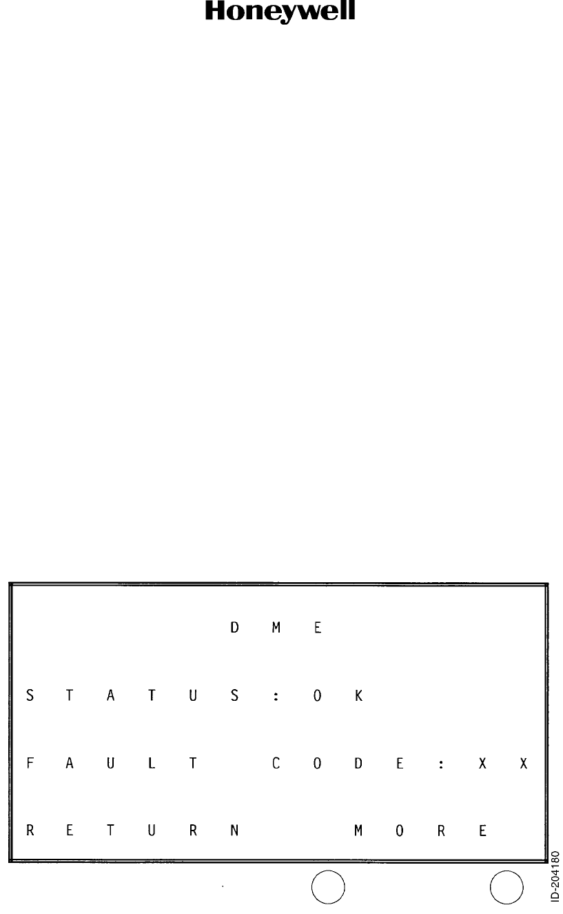
Page 1010
10 Oct 2007
34-51-02
MAINTENANCE MANUAL
DMA-37B DME System
© Honeywell International Inc. Do not copy without express permission of Honeywell.
D. Mainentance Mode for -0101, -0202, and -0303 Only
(1) The maintenance mode is entered from either one of the two Test Complete screens
(Figure 1004 or Figure 1005). The maintenance mode allows troubleshooting of all
components of the DMA-37B DME System, both internal and external.
(2) All pages have the MORE selection on the right key.
• MORE Pressing this key cycles through all of the maintenance pages. When on
the last page, the MORE key causes a return to the first displayed
maintenance screen.
(3) All pages have the RETURN selection on the left key.
• RETURN Pressing this key causes the system to return to the Normal Mode
screen (Figure 1001).
(4) There is no timeout in the maintenance mode when the aircraft is on the ground. But,
while in the air, not pressing a key for five minutes causes the system to return to the
Normal Mode screen (Figure 1001).
(5) Figure 1015 thru Figure 1021 show typical maintenance-mode pages that can be
encountered.
(6) In Figure 1016, row one, PORT X will be either PORT A or PORT B. Lines 2 thru 7
display the status of up to six tuning words by showing the contents of their SSM, Mode,
Ident, Display, and Frequency fields. Mode 0 thru 5 frequencies are displayed if a Mode
0 (standby) frequency is being received. If the DMA-37B is not in standby, then Mode I
thru 6 frequencies will be displayed. Column six displays either I, D, or B, when the Ident
bit is on, when the Display is on, and when both Ident and Display bits are on,
respectively. If the selected port does not meet the minimum total update rate check for
Default Mode then all fields display X.
NOTE: The Status field displays FAILED if either an external or an internal failure is
detected.
Figure 1015. DME Receiver Status (OK, FAILED) Screen
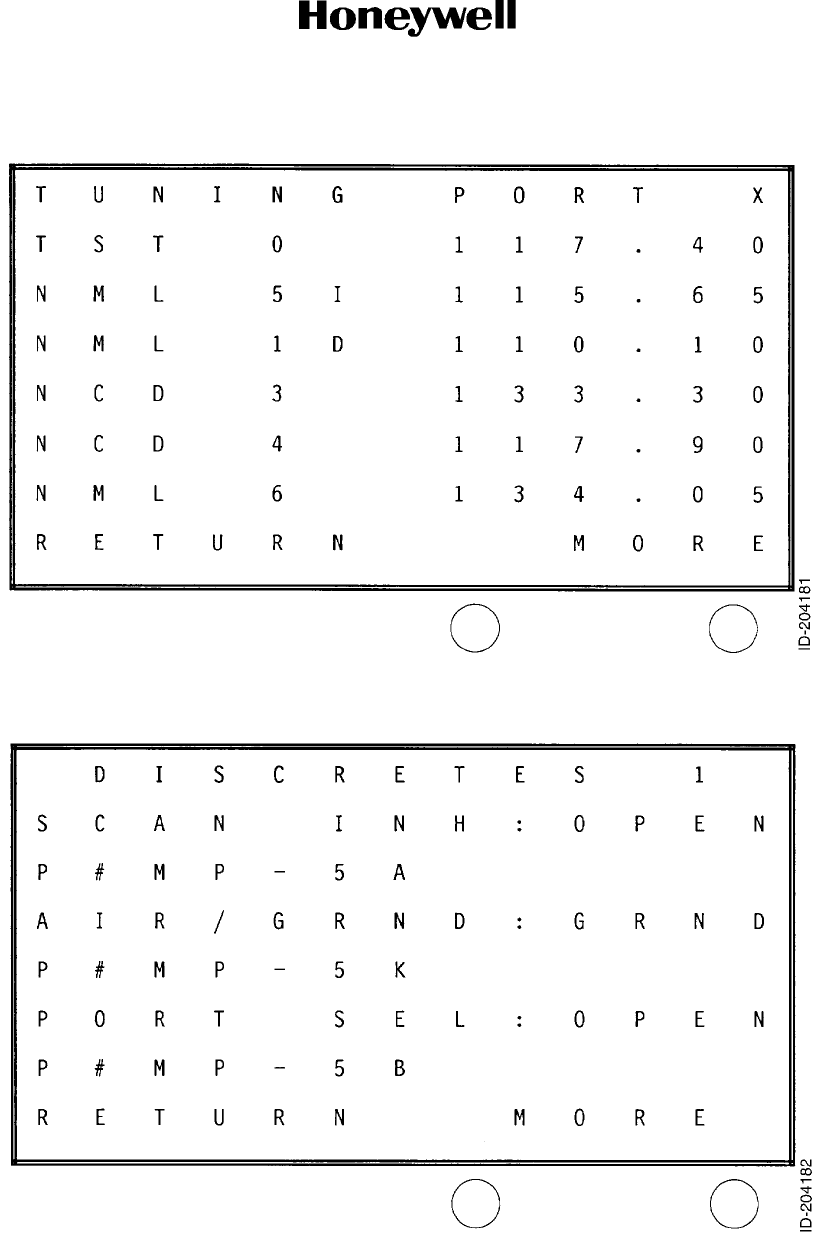
Page 1011
10 Oct 2007
34-51-02
MAINTENANCE MANUAL
DMA-37B DME System
© Honeywell International Inc. Do not copy without express permission of Honeywell.
Figure 1016. Tuning Port Status (NML, TST, NCD, NODA) Screen
Figure 1017. Discrete Input Status Page 1 (OPEN, GRND) Screen
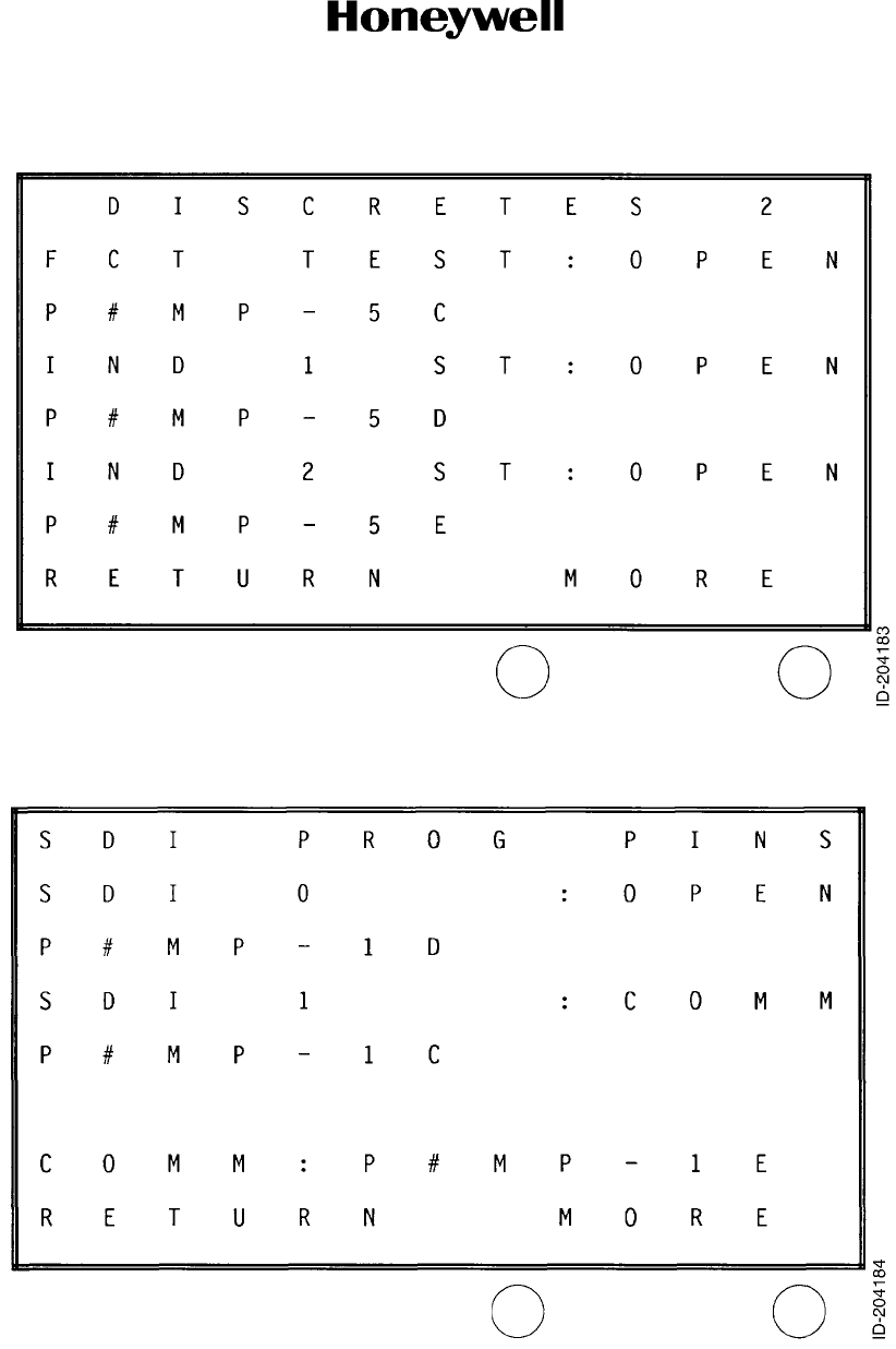
Page 1012
10 Oct 2007
34-51-02
MAINTENANCE MANUAL
DMA-37B DME System
© Honeywell International Inc. Do not copy without express permission of Honeywell.
Figure 1018. Discrete Input Status Page 2 (OPEN, GRND) Screen
Figure 1019. SDI Program Pin Status Page (OPEN, COMM) Screen
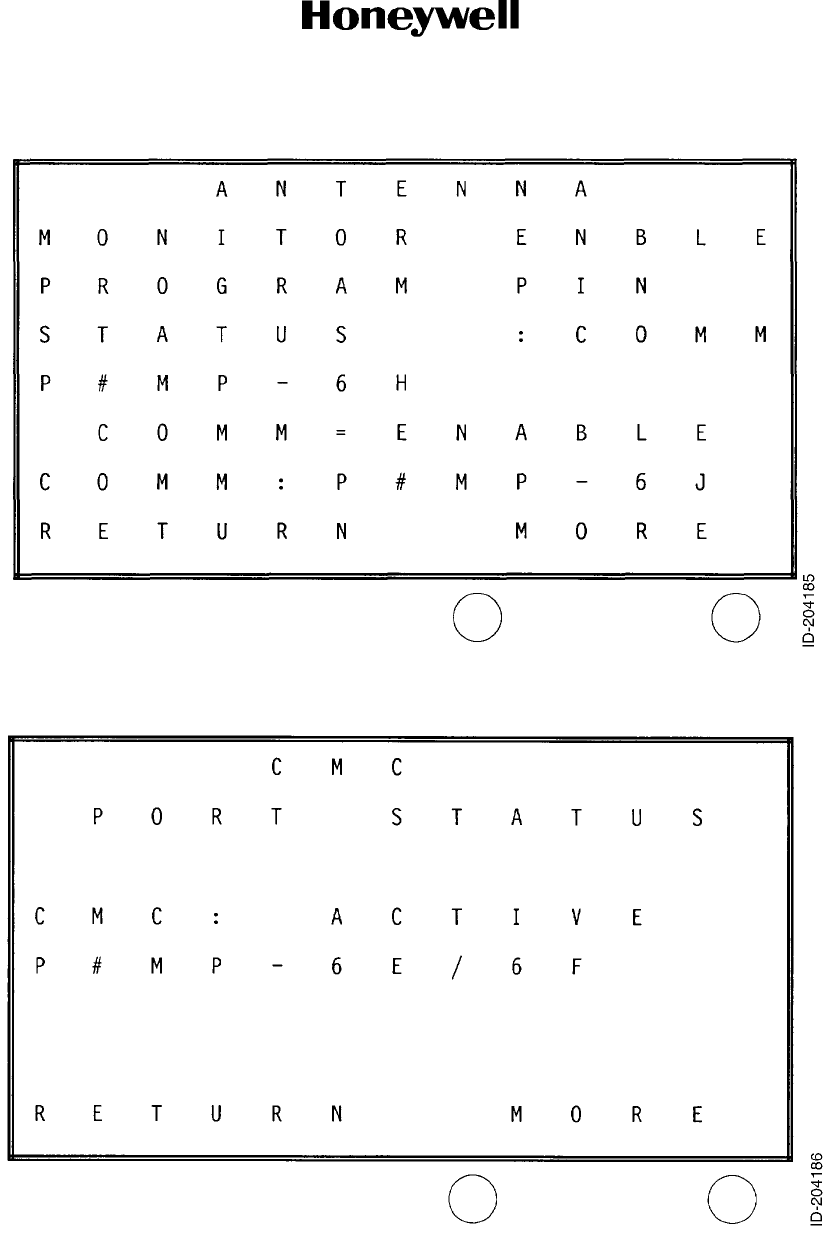
Page 1013
10 Oct 2007
34-51-02
MAINTENANCE MANUAL
DMA-37B DME System
© Honeywell International Inc. Do not copy without express permission of Honeywell.
Figure 1020. Antenna Monitor Program Pin Status Page (OPEN, COMM) Screen
Figure 1021. CMC Port Status (ACTIVE, INACTIVE) Screen

Page 1014
10 Oct 2007
34-51-02
MAINTENANCE MANUAL
DMA-37B DME System
© Honeywell International Inc. Do not copy without express permission of Honeywell.
E. Flight Fault Memory Mode for -0101, -0202, and -0303 Only
(1) When the flight-fault memory contains failures from previous flight legs, an Old Failures
screen (Figure 1022) is presented as the last page of the maintenance mode screens.
This page allows the viewing of previous flight leg failures, one flight leg at a time by
pressing the YES key. Pressing the MORE key from this page bypasses this function
and returns the system back to the first page of the maintenance data.
(2) Once in the flight fault memory mode, flight legs are displayed from the most recent,
backwards. Four pages are required for each flight leg. The first page of each flight leg
contains the date, flight number, aircraft number, and departure/destination stations
(Figure 1023). Three pages follow for each flight leg to contain the 13 possible failures
(Figure 1024).
(3) All flight fault memory pages have the MORE selection on the right key.
• MORE Pressing the key cycles through all of the flight fault memory pages.
When on the last page, the MORE key causes a return to the first page.
(4) All flight fault memory pages have the RETURN selection on the left key.
• RETURN Pressing this key causes the system to return to normal mode
(Figure 1001).
(5) There is no timeout in this mode when the aircraft is on the ground. But, while in the air,
not pressing a key for five minutes causes the system to return to the Normal Mode
screen (Figure 1001).
Figure 1022. Old Failures Page Screen
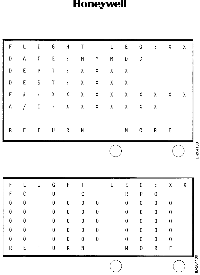
Page 1015
10 Oct 2007
34-51-02
MAINTENANCE MANUAL
DMA-37B DME System
© Honeywell International Inc. Do not copy without express permission of Honeywell.
Figure 1023. Previous Flight Legs Failures First Page Screen
NOTE: FC is fault code, UTC is time, R is repetition count, P is phase, O is origin.
Figure 1024. Previous Flight Legs Failures Data Page Screen
(Three Screens for Each Flight Leg)

Page 1016
10 Oct 2007
34-51-02
MAINTENANCE MANUAL
DMA-37B DME System
© Honeywell International Inc. Do not copy without express permission of Honeywell.
Blank Page

Page 2001
10 Oct 2007
34-51-02
MAINTENANCE MANUAL
DMA-37B DME System
© Honeywell International Inc. Do not copy without express permission of Honeywell.
MAINTENANCE PRACTICES
1. General
A. Description
(1) This section of the manual provides service personnel with installation and maintenance
information for the DMA-37B DME System. Installation instructions are supported by
mechanical outline drawings and an electrical interconnection diagram. These drawings,
located at the back of this section, must be reviewed by the installer, and requirements
peculiar to the airframe must be established before starting the installation.
B. Inspection After Unpacking
CAUTION: THIS EQUIPMENT CONTAINS ELECTROSTATIC DISCHARGE SENSITIVE
(ESDS) DEVICES. EQUIPMENT, MODULES, AND ESDS DEVICES MUST
BE HANDLED WITH APPROPRIATE PRECAUTIONS.
(1) Visually inspect the DMA-37B DME System and all associated equipments for possible
damage which can occur during shipment. Inspect for dents, deep abrasions, chipped
paint, etc. If any equipment is damaged, notify the transportation carrier immediately.
(2) A Honeywell test and inspection record and quality report tag is included with each
shipped unit. This notifies the customer that the necessary production tests and
inspection operations have been performed on that particular unit.
(3) One copy of the quality report tag is affixed to each unit by the first assembly inspector.
As the unit proceeds through production and stock to the shipping area, the appropriate
blocks on the test and inspection record of the tag are stamped. This tag accompanies
the unit when it is shipped to the customer. Customers are requested to complete the
quality report portion of the tag and return it to the Honeywell Quality Assurance
Department, Fort Lauderdale, Florida. This portion of the tag provides Honeywell with
the necessary information required to evaluate shipping methods as well as test and
inspection effectiveness.
(4) Completed cards are accumulated to provide information for a periodic analysis.
C. Preinstallation Testing
(1) The components in the DMA-37B DME System are adjusted and tested prior to
shipment. Therefore, preinstallation testing is not required. However, if preinstallation
testing of the units is desired, refer to the customer acceptance criteria given in the
Component Maintenance Manual for the appropriate unit in the system. Refer to
Paragraph 4 in the INTRODUCTION section of this manual for a list of related
Component Maintenance Manuals.
D. Equipment Changes and Marking
(1) Honeywell uses a standardized marking system to identify equipment and their
subassemblies which have had changes incorporated. Refer to the front of the
appropriate Component Maintenance Manual for a list of Service Bulletins affecting the
unit.
E. Interchangeability
(1) The DMA-37B DME System will operate in any installation that complies with ARINC
characteristic 709-8; it also operates as an DME-37A DME System replacement in any
installation that complies with ARINC 709. See Figure 2006 for particulars.

Page 2002
10 Oct 2007
34-51-02
MAINTENANCE MANUAL
DMA-37B DME System
© Honeywell International Inc. Do not copy without express permission of Honeywell.
2. Installation
A. General
(1) The DMA-37B DME System must be installed in the aircraft in a manner consistent with
acceptable workmanship and engineering practices, and in accordance with the
instructions set forth in this publication. To make sure that the system has been properly
and safely installed in the aircraft, the installer must make a thorough visual inspection
and conduct an overall operational and functional check of the system on the ground
prior to flight.
CAUTION: AFTER INSTALLATION OF THE CABLING AND BEFORE INSTALLATION
OF THE EQUIPMENT, A CHECK MUST BE MADE WITH AIRCRAFT
PRIMARY POWER BEING SUPPLIED TO THE MOUNT CONNECTORS TO
MAKE SURE THAT POWER IS APPLIED ONLY TO THE PINS SPECIFIED
IN FIGURE 2006.
B. Location of Equipment
(1) Location of the DMA-37B DME System in the aircraft is not critical, as long as the
environment is compatible with the equipment design. Refer to the Leading Particulars,
Table 5, in the DESCRIPTION AND OPERATION section of this manual. Forced air
cooling is required for cooling the DMA-37B DME Interrogator in accordance with
ARINC Characteristic 600. The associated cooling equipment must be mounted in
accordance with the manufacturer’s instructions.
(2) Antenna mounting must be in accordance with the manufacturer’s instructions for the
antenna being used. The coaxial cable connecting the antenna to the mount must be as
short and direct as possible and any required bends must be gradual. When two or more
DMA-37B DME Systems are installed in an aircraft, it is necessary to provide adequate
space isolation between antennas of each system to make sure that the use of one unit
does not interfere with reception from another system. A minimum of 35 dB of space
isolation must be provided, and any steps which can be taken to provide further isolation
must be considered.
(3) Control unit location and mounting can be determined by mutual agreement between the
user and airframe manufacturer.
C. Interwiring and Cable Fabrication
(1) General
(a) Figure 2006 is a complete interwiring diagram for a single DMA-37B DME System
and associated components. This diagram requires thorough study before the
installer begins installation of the aircraft wiring.
(b) When two systems are being installed in the aircraft, the interconnecting wiring
shown in Figure 2006, as well as all other installation instructions must be
duplicated.
(c) Cabling must be fabricated by the installer in accordance with Figure 2006. Wires
connected to parallel pins must be approximately the same length, so that the best
distribution of current can be effected. Honeywell recommends that all wires,
including spares, shown in Figure 2006, be included in the fabricated harness.
However, if full ARINC wiring is not desired, the installer must make sure that the
minimum wiring requirements for the features and functions to be used are
incorporated.

Page 2003
10 Oct 2007
34-51-02
MAINTENANCE MANUAL
DMA-37B DME System
© Honeywell International Inc. Do not copy without express permission of Honeywell.
(d) When the cables are installed in the aircraft, they must be supported firmly enough
to prevent movement and must be carefully protected against chafing. Additional
protection must also be provided in all locations where the cables can be subject to
abuse. In wire bundles, the cabling must not be tied tightly together as this tends to
increase the possibility of noise pick-up and similar interference. When routing
cables through the airframe, try to avoid running cables or wire close to power
sources (400-Hz generator, etc). If unavoidable, the cables must cross high-level
lines at a right angle, or high-quality shielded conductors must be used.
(e) If a cable must pass through a bulkhead between pressurized and unpressurized
zones, this passage must conform to the aircraft manufacturer’s specifications.
(f) The assembler must be knowledgeable of any system variations peculiar to the
installation, and must thoroughly understand the complexities associated with
handling related problems of line lengths, capacitance, and of susceptibility to
interference.
(g) Table 2001 lists the determinants that are the responsibility of the installation
agency for fabrication of the wiring harness. See Figure 2006 also.
Table 2001. DMA-37B DME Interrogator Connector Determinants
Pin Type Signal Name Function
MP1A Output Audio Output (HI) An analog output of the demodulated ground
station identification audio signal to the audio
distribution system
MP1B Output Audio Output (LO)
MP1C Input SDI Bit 1 Used for encoding the location (system number)
of the DMA-37B in the aircraft; used with pins
MPID (SDI Bit 0) and MP1E (common)
MP1D Input SDI Bit 0 Used for encoding the location (system number)
of the DMA-37B in the aircraft; used with pins
MPIC (SDI Bit 1) and MP1E (common)
MP1E --- SDI Common Ground for the SDI code inputs from pins MP1C
and/or MP1D
MP1F --- Siggest ARINC 709 Spare No. 1 ---
MP1G Output DME Distance Data Output No. 1 (A) One of two low speed ARINC 429 data output
ports to provide DME distance outputs to other
equipment on the aircraft.
Used to transmit the range words, the DME
ground station identification words, and to repeat
the selected frequency words if received over
the frequency tuning interfaces. Maintenance
data information will also be transmitted on these
ports.
MP1H Output DME Distance Data Output No. 1 (B)
MP1J --- Spare ---
MP1K Output Siggest ARINC 709 Spare No. 2 ---
MP2A --- Spare ---
MP2B --- Spare ---
MP2C --- Spare ---
MP2D --- Spare ---

Page 2004
10 Oct 2007
34-51-02
MAINTENANCE MANUAL
DMA-37B DME System
© Honeywell International Inc. Do not copy without express permission of Honeywell.
MP2E --- Spare ---
MP2F --- Spare ---
MP2G --- Spare ---
MP2H --- Spare ---
MP2J --- Spare ---
MP2K --- Spare ---
MP3A Input Freq/Funct Select Data I/P Port A (A) One of two low speed 429 data input ports to
receive tuning information, Ident and Display
channel selection, DME Mode and
Source/Destination Identifier selection.
MP3B Input Freq/Funct Select Data I/P Port A (B)
MP3C --- Spare ---
MP3D Input Freq/Funct Select Data I/P Port A (A) One of two low speed 429 data input ports to
receive tuning information, Ident and Display
channel selection, DME Mode and
Source/Destination Identifier selection.
MP3E Input Freq/Funct Select Data I/P Port A (B)
MP3F --- Spare ---
MP3G Output DME Distance Data Output No. 2 (A) One of two low speed ARINC 429 data output
ports to provide DME distance outputs to other
equipment on the aircraft.
Used to transmit the range words, the DME
ground station identification words, and to repeat
the selected frequency words if received over
the frequency tuning interfaces. Maintenance
data information will also be transmitted on these
ports.
MP3H Output DME Distance Data Output No. 2 (B)
MP3J --- Spare ---
MP3K --- Spare ---
MP4A --- Spare ---
MP4B --- Spare ---
MP4C --- Spare ---
MP4D --- Spare ---
MP4E --- Spare ---
MP4F --- Spare ---
MP4G --- Spare ---
MP4H --- Spare ---
MP4J --- Spare ---
MP4K --- Spare ---
Table 2001. DMA-37B DME Interrogator Connector Determinants (cont)
Pin Type Signal Name Function

Page 2005
10 Oct 2007
34-51-02
MAINTENANCE MANUAL
DMA-37B DME System
© Honeywell International Inc. Do not copy without express permission of Honeywell.
MP5A Input Default Scan Inhibit Discrete input indicates default mode of
operation.
If this program pin is grounded when no tuning
input is received and like-labelled words fall
below five per second, DMA-37B automatically
reverts to standby operation and invalidates its
computed range measurement.
If this program pin is open when no tuning input
is received and like-labelled words fall below five
per second, DMA-37B automatically reverts to
free scan operation.
MP5B Input Freq/Funct Data Source Select Discrete Discrete input determines which input tuning port
will be selected. Port A (MP3A & MP3B) are
used when the discrete is in the ground state.
Port B (MP3D & MP3E) are used when the
discrete is in the open state. When the DMA-37B
is installed in an aircraft in which a dedicated
control panel supplies the tuning information,
Port B must be used. When the DMA-37B is
installed in an aircraft in which a Centralized
Radio Management system supplies the tuning
information, Port A must be used as the primary
control source, and Port B as the secondary or
backup control source.
MP5C Input Functional Test Discrete Discrete input that activates LRU functional test
function. Gnd/Low = activate functional test.
MP5D Input Indicator No. 1 Status Input Discrete input indicates the status of indicator
No. 1. The input is open to indicate the indicator
has failed.
MP5E Input Indicator No. 2 Status Input Discrete input indicates the status of indicator
No. 2. The input is open to indicate the indicator
has failed.
MP5F --- Spare ---
MP5G --- Spare ---
MP5H --- Spare ---
MP5J Input Reserved for Maintenance Display
Reset
Resets failure reporting of DME System.
MP5K Input Air/Ground Logic Discrete input is open when the aircraft is on the
ground and grounded when the aircraft is
airborne.
MP6A --- Spare ---
MP6B --- Spare ---
MP6C --- Spare ---
MP6D --- Spare ---
Table 2001. DMA-37B DME Interrogator Connector Determinants (cont)
Pin Type Signal Name Function

Page 2006
10 Oct 2007
34-51-02
MAINTENANCE MANUAL
DMA-37B DME System
© Honeywell International Inc. Do not copy without express permission of Honeywell.
MP6E Input CFDS Data Bus Input A Low speed ARINC 429 data input port receives
maintenance data from the CFDS/CMC
MP6F Input CFDS Data Bus Input B
MP6G --- Spare ---
MP6H Input DC Antenna Monitor Enable Discrete input indicates whether or not the
antenna monitoring function is activated.
Antenna monitoring is activated when this input
is connected to the Antenna Monitor Common
(MP6J).
MP6J Output DC Antenna Monitor Common Discrete supplies the return (ground) for the
Antenna Monitor Enable (MP6H) when antenna
monitoring is active.
MP6K --- Spare ---
MP7A --- Spare ---
MP7B Output 115V AC Indicator Panel Power Out
(HOT)
115 V ac, 400Hz is available on these pins for
routing to an indicator panel in those installations
which use an individual indicator panel.
MP7C Output 115V AC Indicator Panel Power Out
(COLD)
MP7D --- Spare ---
MP7E --- Spare ---
MP7F --- Spare ---
MP7G --- Spare ---
MP7H Output 115V AC Control Panel Power Out
(HOT)
115 V ac, 400Hz is available on these pins for
routing to a control panel in those installations
which use an individual control panel rather than
an integrated frequency/function selection
system supplied with aircraft power directly.
MP7J Output 115V AC Control Panel Power Out
(COLD)
MP7K --- Spare ---
BP1 Input 115VAC (HOT)
(2A Circuit Breaker)
Primary input power to DMA-37B
BP2 --- --- ---
BP3 --- --- ---
BP4 --- --- ---
BP5 --- --- ---
BP6 --- --- ---
BP7 Input 115VAC (COLD)
(AC common)
Primary power return
BP8 --- --- ---
BP9 --- --- ---
Table 2001. DMA-37B DME Interrogator Connector Determinants (cont)
Pin Type Signal Name Function

Page 2007
10 Oct 2007
34-51-02
MAINTENANCE MANUAL
DMA-37B DME System
© Honeywell International Inc. Do not copy without express permission of Honeywell.
(2) Reserved and Spare Wires
(a) If the installer does not wish to connect all wires, he can select wires reserved for
optional functions which his system does not contain and delete these wires. He
must also decide which future spare wires to include in the installation. Reserved
and spare wires are identified in interwiring diagram Figure 2006.
(3) Source/Destination Identifier (SDI) Encoding
(a) A connection is required from the common pin MP6C to the appropriate
source/destination identifier (SDI) pin to identify each DMA-37B in multiple system
installations. Installations having only one DMA-37B must include a connection
identifying it as the No. 1 system. These connections must not be omitted from any
installation. See Figure 2006 notes for the SDI encoding scheme for pins MP1C,
MP1D, and MP1E.
D. Installation of System
(1) Mounting Base
(a) The selected mounting base for the DMA-37B DME Interrogator must be wired
according to the system interwiring diagram, Figure 2006, and installed according
to the manufacturer’s instructions. The mounts are designed to be removed without
rewiring the connectors. Follow the equipment manufacturer’s installation
instructions to install the mount into the airframe.
(b) To wire the mounts into the system, first remove the mount connector cover and
connector plate assembly. Then crimp or solder (as applicable) the interconnecting
wiring to the appropriate connector pins. Finally, return the connector plate
assembly and cover to their original positions.
NOTE: To allow for inspection or repair of the connector, or the wiring to the
connector, sufficient lead length must be left so that the rear connector
assembly can be pulled forward several inches when the mounting
hardware for the rear connector assembly is removed. A bend must be
made in the harness near the connector to allow water droplets, that might
form on the harness from condensation, to drip off at the bend and not
collect at the connector.
BP10 --- --- ---
BP11 Input Chassis Ground Chassis ground
BP12 Input/
Output
Suppressor This analog port is both an input and an output.
When the DMA-37B is receiving, this line will
receive suppression pulses from other pulse
equipment, and when the DMA-37B is
transmitting, this line will transmit suppression
pulses to other pulse equipment.
BP13 Output Reserved for Video Output Output for the video output signal from the
DMA-37B receiver.
Table 2001. DMA-37B DME Interrogator Connector Determinants (cont)
Pin Type Signal Name Function

Page 2008
10 Oct 2007
34-51-02
MAINTENANCE MANUAL
DMA-37B DME System
© Honeywell International Inc. Do not copy without express permission of Honeywell.
(2) DMA-37B DME Interrogator
(a) The DMA-37B DME Interrogator is installed in the mount as follows:
1Slide the DMA-37B into the mount until the guide pins are aligned and the
electrical connectors are firmly engaged.
2Secure the front of the DMA-37B to the mount by tightening the two knurled
screw clamps (located on the front of the mount) until they are firmly seated
over hold-down hooks located on the front of the unit.
3Safety-wire the two screw clamps.
(3) NAV Control Panel
(a) The selected NAV control panel must be wired according to the system interwiring
diagram, Figure 2006, and the manufacturer's instructions. For installation
procedure and mounting dimensions, refer to the applicable manufacturer's
instructions.
(4) DME Display
(a) The selected DME display must be mounted in the aircraft instrument panel to
provide easy visibility and to conform to customer requirements and the installation
instructions of the manufacturer. Interwiring must be in accordance with
Figure 2006, system interwiring diagram.
(5) DME Antenna
(a) Install the DME antenna in accordance with the manufacturer's instructions.
Maximum insertion loss of the coax run from the DMA-37B to the antenna is 3 dB.
(6) Mutual Suppression
(a) In dual DMA-37B installations, mutual suppression pulse connections are required
between units.
(b) Mutual suppression pulse connectors are also required between DMA-37B units, air
traffic control (ATC) transponders, and Traffic Alert and Collision Avoidance System
(TCAS).
3. Inspection and System Check Procedures
CAUTION: INSPECTION AND CHECK PROCEDURES FOR THE DMA-37B INCLUDES
CHECKOUT OF ALL INTERFACING UNITS THAT CAN AFFECT
PERFORMANCE OF THE DMA-37B.
A. Inspection
(1) Table 2002 is a visual inspection check procedure and must be performed after system
installation, prior to system checkout. In addition, the procedure must be used as a
periodic inspection check.
Page 2009
10 Oct 2007
34-51-02
MAINTENANCE MANUAL
DMA-37B DME System
© Honeywell International Inc. Do not copy without express permission of Honeywell.
B. System Checkout
(1) General
(a) After installation of the DMA-37B DME System and inspection of the equipment in
accordance with Table 2002, perform a continuity and visual check of the system
interwiring in accordance with Paragraph 3.B.(2). A post-installation test in
accordance with Paragraph 3.B.(3) must then be performed.
(2) System Interwiring Check
(a) Visually check the system interwiring for abnormalities, such as cables rubbing
unprotected metal edges or tightly stretched cables. Check continuity of all
interwiring. In particular, check the following:
• Check that the DMA-37B is properly installed and the hold-down screw clamps
are tight.
• Check the wiring harness connectors for security and connection to the
DMA-37B.
• Check that the antenna transmission line connectors are securely fastened.
• Check that the control panel connectors are securely fastened.
• Check that the DME display is securely fastened.
• Check that the cables do not interfere with aircraft controls or other equipment.
(3) Post-lnstallation Check
(a) Test Equipment Required
1Table 2003 lists a ramp test set that can be used to determine if the DMA-37B
DME System is operating properly. Test sets other than that listed in Table 2003
can be used if their characteristics fulfill those listed under Characteristics
Required.
Table 2002. Inspection/Check Procedures
Equipment Inspection/Check Procedure
4 MCU Unit Mount As defined by manufacturer's instructions.
DMA-37B DME Interrogator 1. Check that unit is fully inserted in mount and that
Interrogator the knurled screw clamps which secure the unit
in the mount are tight and safety wired.
2. Inspect the case for deformation, dents, corrosion, and
damage to finish; make sure that ventilation holes in the unit
are not clogged.
NAV Control Panel As defined by manufacturer's instructions.
DME Display As defined by manufacturer's instructions.
DME Antenna As defined by manufacturer's instructions.
Table 2003. Table of Test Equipment
Description Characteristics Required Representative Type
Transponder and DME
Test Set
Must have an X-channel and a Y-channel output.
Selected range must be variable from 0.1 to 400
nautical miles. Must transmit an ident tone.
Instrument Flight Research
Corp. (IFR) Model ATC-6OOA
or equivalent
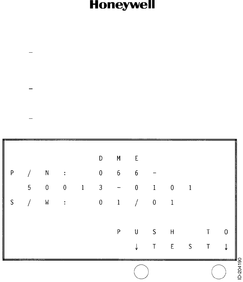
Page 2010
10 Oct 2007
34-51-02
MAINTENANCE MANUAL
DMA-37B DME System
© Honeywell International Inc. Do not copy without express permission of Honeywell.
(b) DMA-37B Initiated System Test, -0101, -0202, and -0303 Only
1A functional self test of the DMA-37B DME System can be initiated by pressing
the test key pushbutton switch as designated on the front panel LCD
(Figure 2001). Although the normal-mode screen indicates that this is actuated
from the right key, the left key has the same function if pressed while the
DMA-37B LCD is in its normal mode.
2The self-test mode starts by displaying the Test in Progress screen
(Figure 2002) one second after pressing the test key. This is displayed for five
seconds with a moving thermometer along the bottom of the LCD indicating the
progress of the test from one to five seconds.
3The Normal-Mode screen (Figure 2001) is displayed for the first second of the
test sequence.
Figure 2001. Typical Normal Mode Screen
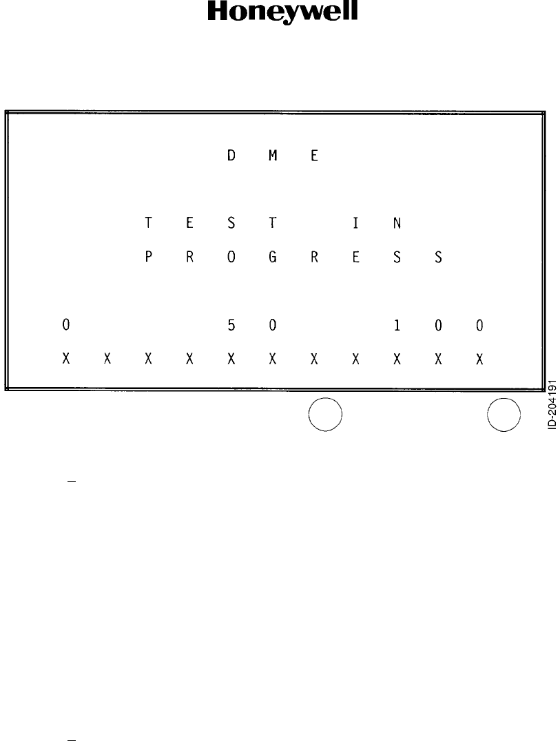
Page 2011
10 Oct 2007
34-51-02
MAINTENANCE MANUAL
DMA-37B DME System
© Honeywell International Inc. Do not copy without express permission of Honeywell.
Figure 2002. Test in Progress Screen
4Once complete, the Test Complete, No Failures screen is displayed
(Figure 2003), or the Test Complete, Failures screen is displayed
(Figure 2004). Both screens contain two key selections each: MAINT and
RETURN or MAINT and WHY?, respectively.
• MAINT For both screens, MAINT is located on the left key. This allows
the initiation of the extended maintenance pages of the system
for troubleshooting. Refer to Paragraph D of the FAULT
ISOLATION section of this manual.
• RETURN In the Test Complete, No Failures screen, the RETURN key to
the right returns the system to its normal mode screen
(Figure 2001).
• WHY? In the Test Complete, Failures screen, the WHY? key to the right
puts the system into the display-failures mode where individual
system failures are displayed one on each page. Refer to
Paragraph C of the FAULT ISOLATION section of this manual.
5While in the self-test mode, not pressing either key for five minutes causes the
system to return to the Normal Mode screen (Figure 2001).
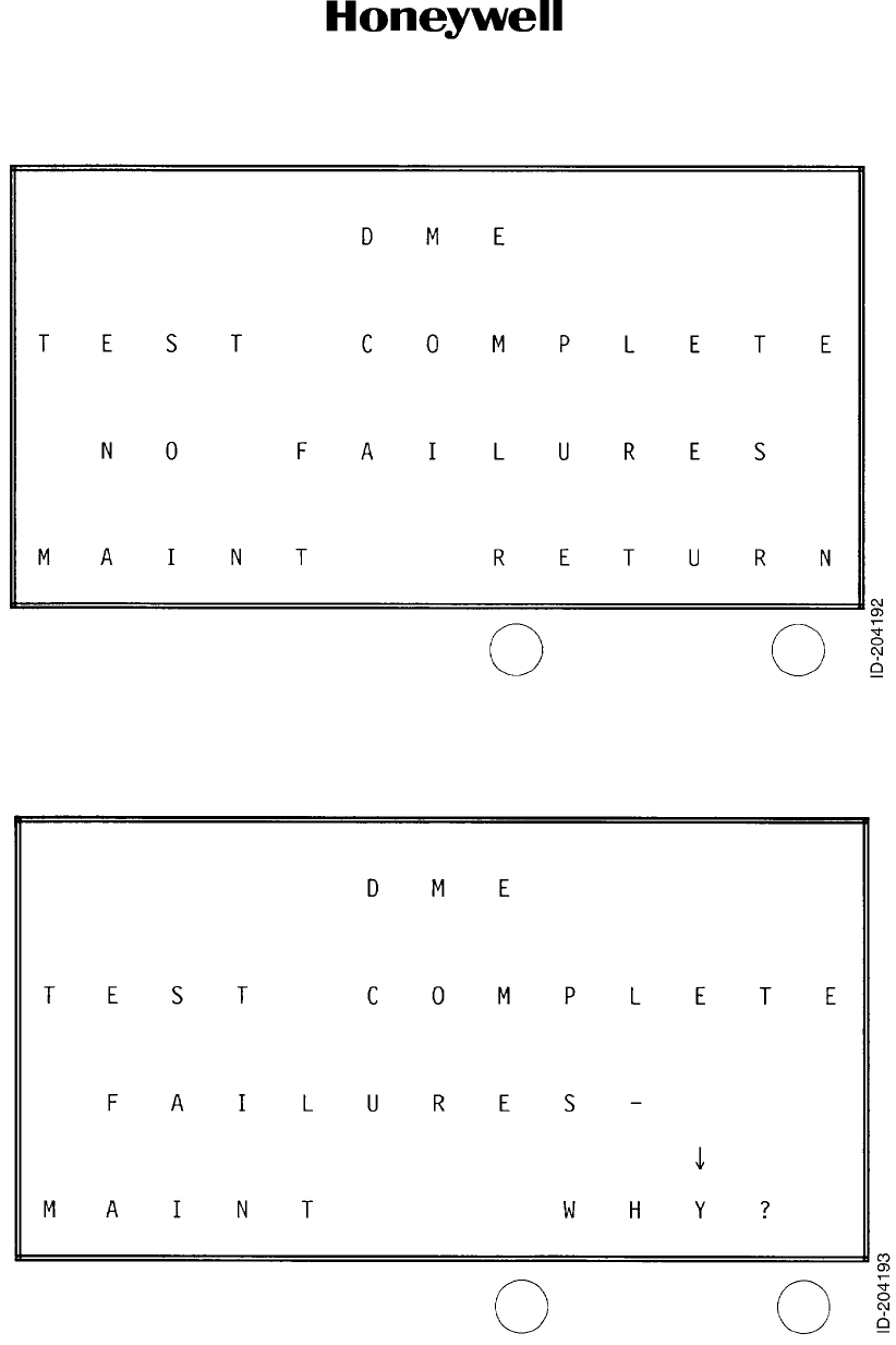
Page 2012
10 Oct 2007
34-51-02
MAINTENANCE MANUAL
DMA-37B DME System
© Honeywell International Inc. Do not copy without express permission of Honeywell.
Figure 2003. Test Complete, No Failures Screen
Figure 2004. Test Complete, Failures Screen

Page 2013
10 Oct 2007
34-51-02
MAINTENANCE MANUAL
DMA-37B DME System
© Honeywell International Inc. Do not copy without express permission of Honeywell.
(c) Front Panel Test Initiation, -1101 and -1212 Only
1On the front panel, observe that the green status LED is lit.
2On the front panel, push the self test button.
3Make sure that all LEDs turn amber and then turn green (indicating normal
operation).
(d) Cockpit-Initiated System Test
1If provisions have been made in the aircraft installation for cockpit initiated
DMA-37B self-test procedure, that procedure must be verified. The results of
the test can be indicated on the EFIS or DME displays depending upon the
installation.
(e) Ramp test
NOTE: The following test instructions are written in general terms. Refer to
the DME test set instruction manual for specific DME test set
operating instructions.
1Set up ramp test set as recommended in accordance with test set
manufacturer's instruction manual. Position DME ramp test set in vicinity of
aircraft.
2Apply power to DMA-37B DME System.
3If the Post-lnstallation Check System Test has not been accomplished, perform
the System Test as described in Paragraph 3.B.(3) to verify self-test operation.
4Set NAV control to select a DME frequency corresponding to that set in the
DME ramp test set.
5Verify that the DME distance readout is equal to that set in the DME ramp test
set.
6Set DME ramp test set for an audio Ident output.
7Verify that the audio Ident is heard through the cockpit speaker.
8Repeat steps 4 and 5 for one or more additional frequencies and distances.
(f) Flight Tests
1Preflight Test
aGeneral
(1) The following test procedure gives instructions for a preflight test
which make sures that the DMA-37B DME System is functioning in an
acceptable manner prior to takeoff.
bTest Procedures
(1) Perform the System Test, Cockpit Initiated procedure as described in
Paragraph 3.B.(3)(d) of this section.
2In-Flight Confidence Test
aGeneral
(1) Upon completion of the post-installation and preflight checks, a local
flight can be made to verify system operation. Perform the following
In-Flight Confidence Test procedures.

Page 2014
10 Oct 2007
34-51-02
MAINTENANCE MANUAL
DMA-37B DME System
© Honeywell International Inc. Do not copy without express permission of Honeywell.
bTest Procedures
(1) Apply power to DMA-37B DME System.
(2) Set NAV control to frequency of a nearby DME station.
(3) Note distance readout of DME display to the selected DME station and
compare this to calculated distance on a visual flight rules (VFR) chart.
Verify that the two distances agree within 0.1 nautical mile.
4. Removal and Replacement
A. Removal
(1) Loosen the two knurled screw clamps (located on the front of mount) that secure the
DMA-37B to the mount.
(2) Gently pull the DMA-37B forward until it is disconnected from the rear connector and
guide pins.
B. Replacement
(1) Slide the DMA-37B onto the tray of the mount and then gently push the DMA-37B until
the guide pins are aligned and the connectors make a firm connection.
(2) Tighten the two knurled screw clamps located on the front of the mount until they are
firmly seated over the hold-down hooks located on the front of the DMA-37B.
(3) Safety wire the two knurled screw clamps.
5. Maintenance Procedures
A. Adjustments and Alignments
(1) There are no adjustments or alignments required for the DMA-37B DME System. All
alignment and adjustment procedures are accomplished during bench maintenance.
The technician must remove the unit from the aircraft and reference must be made to
the related maintenance manual when unit performance indicates an adjustment or an
alignment is required.
B. System Protection
(1) The system must be protected by a 2-ampere circuit breaker located at the circuit
breaker panel in the aircraft.
C. Lubrication Practices
(1) There are no requirements for periodic lubrication of any DMA-37B DME System
components while mounted in the aircraft. Reference must be made to the applicable
maintenance manual for lubrication procedures during routine maintenance of individual
units. Refer to Paragraph 4 in the INTRODUCTION section of this manual for a list of
related maintenance manual publications.
D. Cleaning
(1) When deemed necessary, depending upon the environment to which the equipment is
exposed and the intensity of use, periodic cleaning must be performed. Any dust on the
DMA-37B DME System LRUs must be wiped off with a lint-free cloth.
NOTE: Any cleaning of equipment interiors must be limited to that required when
performing overhaul (bench-type) work.
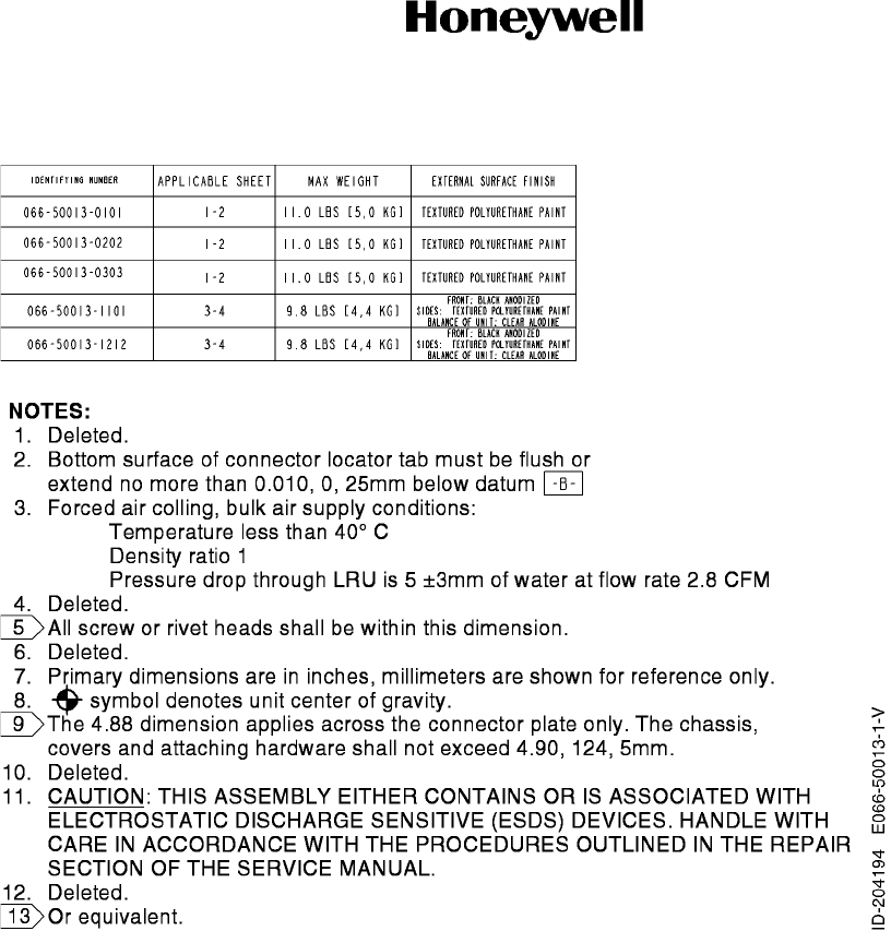
10 Oct 2007
34-51-02
MAINTENANCE MANUAL
DMA-37B DME System
© Honeywell International Inc. Do not copy without express permission of Honeywell.
Figure 2005. (Sheet 1). DMA-37B DME Interrogator Dimensional Outline Drawing
Page 2015/2016
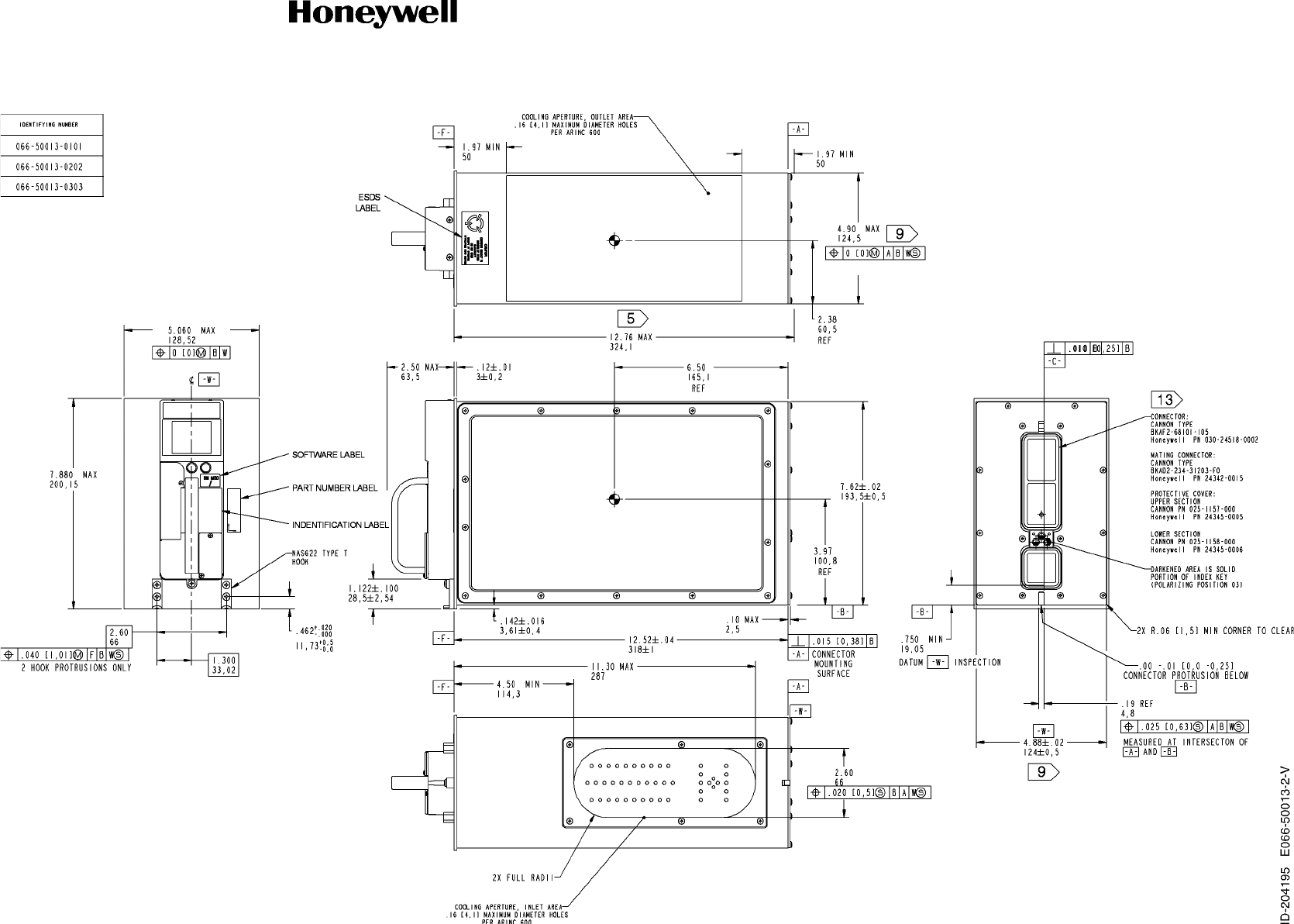
10 Oct 2007
34-51-02
MAINTENANCE MANUAL
DMA-37B DME System
© Honeywell International Inc. Do not copy without express permission of Honeywell.
Figure 2005 (Sheet 2). DMA-37B DME Interrogator Dimensional Outline Drawing
Page 2017/2018
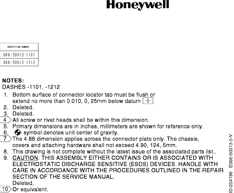
10 Oct 2007
34-51-02
MAINTENANCE MANUAL
DMA-37B DME System
© Honeywell International Inc. Do not copy without express permission of Honeywell.
Figure 2005 (Sheet 3). DMA-37B DME Interrogator Dimensional Outline Drawing
Page 2019/2020
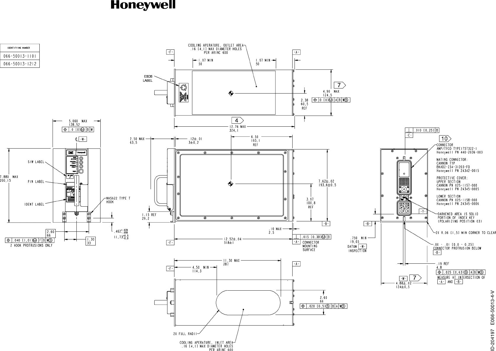
10 Oct 2007
34-51-02
MAINTENANCE MANUAL
DMA-37B DME System
© Honeywell International Inc. Do not copy without express permission of Honeywell.
Figure 2005 (Sheet 4). DMA-37B DME Interrogator Dimensional Outline Drawing
Page 2021/2022
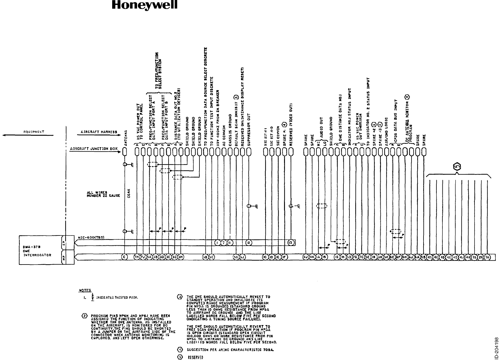
10 Oct 2007
34-51-02
MAINTENANCE MANUAL
DMA-37B DME System
© Honeywell International Inc. Do not copy without express permission of Honeywell.
Figure 2006. DMA-37B DME System Interwiring Diagram
Page 2023/2024